EP3315455A1 - Mast support device - Google Patents
Mast support device Download PDFInfo
- Publication number
- EP3315455A1 EP3315455A1 EP17198590.6A EP17198590A EP3315455A1 EP 3315455 A1 EP3315455 A1 EP 3315455A1 EP 17198590 A EP17198590 A EP 17198590A EP 3315455 A1 EP3315455 A1 EP 3315455A1
- Authority
- EP
- European Patent Office
- Prior art keywords
- channel
- moveable member
- impact dampening
- mast
- block
- Prior art date
- Legal status (The legal status is an assumption and is not a legal conclusion. Google has not performed a legal analysis and makes no representation as to the accuracy of the status listed.)
- Granted
Links
Images


Classifications
-
- B—PERFORMING OPERATIONS; TRANSPORTING
- B66—HOISTING; LIFTING; HAULING
- B66F—HOISTING, LIFTING, HAULING OR PUSHING, NOT OTHERWISE PROVIDED FOR, e.g. DEVICES WHICH APPLY A LIFTING OR PUSHING FORCE DIRECTLY TO THE SURFACE OF A LOAD
- B66F9/00—Devices for lifting or lowering bulky or heavy goods for loading or unloading purposes
- B66F9/06—Devices for lifting or lowering bulky or heavy goods for loading or unloading purposes movable, with their loads, on wheels or the like, e.g. fork-lift trucks
- B66F9/075—Constructional features or details
- B66F9/08—Masts; Guides; Chains
Definitions
- the present disclosure relates to masts for lift trucks, and in particular to devices for relieving lift chain tension for such masts.
- lift chains on certain lift truck masts are typically under constant, or nearly constant, tension.
- the lift chains may be under constant tension.
- some lift trucks in certain applications, such as empty container handling the lift chains rarely, if ever, are relieved from being tensioned.
- Some lift truck lift chains therefore carry a relatively large proportion of the rated load for a lift truck, even when not lifting a load, because of the construction, kinematics, dimensions, and weight of attachments secured to the mast.
- the present inventors have also recognized that maintaining lift chains under constant, or nearly constant, tension may inhibit effective lubrication of such chains.
- the present inventors have also recognized that maintaining lift chains under constant, or nearly constant, tension typically reduces lift chain life.
- a two-stage mast 5 may carry a moveable member, such as empty container handling attachment 10, which is vertically translatable along the two-stage mast 5 via one or more lift chains 15.
- the empty container handling attachment 10 may be constrained in channels 20 that are formed in mast columns 25.
- the moveable member may be other suitable attachments.
- an impact dampening block 30 may be located proximate to the bottom of an outer mast section 35. Only one impact dampening block 30 is illustrated in Fig. 2 proximate one of the mast columns 40, however an identical impact dampening block 30 is included proximate the other mast column 40.
- Each mast column 40 includes a channel 45 formed therein.
- each impact dampening block 30 may be located proximate an end of a channel 45 that is proximate to the ground such that each dampening block 30 is aligned with a center of its corresponding channel 45.
- the dampening blocks 30 may not be contained within the footprint of channel 45, but may be offset such that each dampening block 30 is contained, at least partially, within the footprint of channel 20 ( Fig. 3 ).
- impact dampening blocks 30 may be secured to end caps 50.
- end caps 50 are formed as part of plate 55 that is secured to the outer mast section 35, via welding, for example.
- the impact dampening blocks 30 are bolted to the end caps 50, however, other suitable manners for securing the impact dampening blocks 30 may be used, for example, adhesives.
- impact dampening blocks, such as impact dampening blocks 30, may be secured within a footprint of a channel other than by being secured to an end cap, for example, by being secured to one of the walls forming channel 20.
- Impact dampening blocks 30 may be located on end caps 50 such that the impact dampening blocks 30 do not interfere with movement of the inner mast section 37.
- mast columns 25 of the inner mast section 37 contact the plate 55 without contacting the impact dampening blocks 30.
- the impact dampening blocks 30 are located on the end caps 50 such that each impact dampening block 30 is substantially centered within its corresponding channel 20 when the inner mast section 37 is at its fully lowered position. Such centering may locate each impact dampening block 30 to receive a roller 60 ( Fig. 4 ).
- impact dampening blocks, such as impact dampening blocks 30, may contact portions of an inner mast section, such as inner mast section 37.
- each impact dampening block 30 may include a cut-out 65 ( Figs. 6 and 7 ) that matches the outer contour of the rollers 60, which may facilitate self-centering of the rollers 60 with respect to the impact dampening blocks 30.
- the container handling attachment 10 may be further lowered such that the impact dampening blocks 30 compress, and thus receive some of the weight of the container handling attachment 10.
- the lift chain 15 has at least some of the tension removed.
- lowering the container handling attachment 10 onto the impact dampening blocks 30 relieves at least some of the tension from the lift chain 15.
- container handling attachment 10 may weigh approximately 4,500 kilograms (kg).
- the lift chain 15 itself may weigh approximately 16.4 kg.
- the lift chain 15 may only need to bear its own weight (i.e., approximately 16.4 kg), which may result in an approximately 99.28% reduction in weight carried by each of the two chains, which may result in a corresponding relief in tension from the lift chain 15.
- container handling attachment may weigh approximately 6,500 kg.
- the lift chain 15 itself may weight approximately 26.2 kg.
- the lift chain 15 may only need to bear its own weight (i.e., approximately 26.2 kg), which may result in an approximately 99.20% reduction in weight carried by each of the two chains, which may result in a corresponding relief in tension from the lift chain 15.
- the impact dampening blocks 30 are made of a plastic material, preferably nylon or ultra-high-molecular-weight polyethylene, have a height of approximately 40 millimeters (mm), a width of approximately 70 mm, a length of approximately 200 mm, and a cut-out 65 with a diameter of approximately 283 mm.
- a plastic material preferably nylon or ultra-high-molecular-weight polyethylene
- springs may be included to facilitate dampening when the moveable member contacts the impact dampening blocks, for example, coil springs may be included around bolts that hold the impact dampening block body in place.
- Fig. 8 illustrates an example embodiment where the impact dampening blocks 30A are a composite between a metallic section 70 and a plastic section 75.
- an adhesive may be used to secure the plastic section 75 to the metallic section 70.
- a spring such as a wave spring 72, or a leaf spring (not illustrated) or coil spring (not illustrated), may be located between an impact dampening block body (such as metallic section 70A) and an end cap (such as plastic section 75A).
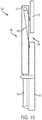
- Fig. 9 illustrates an alternate embodiment where the impact dampening blocks 30B may be formed from two parts that bookend a roller 60B when the roller 60B is lowered onto the impact dampening blocks 30B.
- Impact dampening blocks 30B are optionally attached to end caps 50B and are located such that the walls of channel 20B do not contact the impact dampening blocks 30B.
- the weight of a container handling attachment (not illustrated in Fig. 9 ) is borne by the plate 55B when the container handling attachment contacts the impact dampening blocks 30B.
- Other suitable shapes and arrangements may be used for form impact dampening blocks.
- the outer mast stage 105 comprises two mast columns 110 (only the right mast column 110 is shown).
- the inner mast stage 115 comprises two mast columns 120 (only the right mast column 120 is shown).
- An attachment 125 is moveably attached to the inner mast stage 115. Hydraulic cylinders 130 move the inner mast stage 120 with respect to the outer mast stage 105. When the inner mast stage 115 moves with respect to the outer mast stage 105, lift chains 140 cause the attachment 125 to move with respect to the inner mast stage 115.
- dampening blocks 30 may be located within the footprint of channel 20 ( Fig. 3 ).
- a first set of dampening blocks may be located in the footprint of channels of the mast columns 110 and a second set of dampening blocks may be located in the footprint of channels of the mast columns 120.
- the first set of dampening blocks may receive rollers attached to the inner mast stage 115 (which is a moveable member) when the inner mast stage 115 is lowered and its rollers engage the first set of dampening blocks.
- the second set of dampening blocks may receive rollers attached to the attachment 125 (which is a moveable member) to relieve, or partially relieve, tension from lift chains 140 when the attachment 125 is lowered and its rollers engage the second set of dampening blocks.
Landscapes
- Engineering & Computer Science (AREA)
- Transportation (AREA)
- Structural Engineering (AREA)
- Civil Engineering (AREA)
- Life Sciences & Earth Sciences (AREA)
- Geology (AREA)
- Mechanical Engineering (AREA)
- Forklifts And Lifting Vehicles (AREA)
Abstract
Description
- The present application claims priority to
U.S. Patent Application No. 62/414,184, filed October 28, 2016 - The present disclosure relates to masts for lift trucks, and in particular to devices for relieving lift chain tension for such masts.
- The present inventors have recognized that lift chains on certain lift truck masts are typically under constant, or nearly constant, tension. For example, when the mast is not fully lowered with an attachment resting on the ground, the lift chains may be under constant tension. For some lift trucks in certain applications, such as empty container handling, the lift chains rarely, if ever, are relieved from being tensioned. Some lift truck lift chains therefore carry a relatively large proportion of the rated load for a lift truck, even when not lifting a load, because of the construction, kinematics, dimensions, and weight of attachments secured to the mast.
- The present inventors have also recognized that maintaining lift chains under constant, or nearly constant, tension may inhibit effective lubrication of such chains. The present inventors have also recognized that maintaining lift chains under constant, or nearly constant, tension typically reduces lift chain life.
-
-
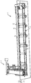
Fig. 1 is a front, left orthogonal sectional view of an example two-stage mast including impact dampening blocks. -
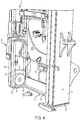
Fig. 2 is a view of the bottom portion ofFig. 1 with the inner mast stage removed. -
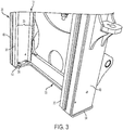
Fig. 3 is a view of the bottom portion ofFig. 1 with the inner mast stage illustrated. -
Fig. 4 is a view of the bottom portion ofFig. 1 with the inner mast stage and an attachment roller illustrated. -
Fig. 4A is a partial cut-away view of the embodiment ofFig. 1 showing an attachment roller engaging an impact dampening block. -
Fig. 4B is a close-up view of the attachment roller engaging the impact dampening block ofFig. 4A . -
Fig. 5 is a close-up view ofFig. 1 . -
Fig. 6 is a front view of the impact dampening block ofFig. 2 . -
Fig. 7 is a top view of the impact dampening block ofFig. 6 . -
Fig. 8 is a front view of another embodiment of an impact dampening block. -
Fig. 8a is a view of another embodiment of an impact dampening block. -
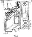
Fig. 9 is a side cut-away view of another embodiment. -
Fig. 10 is a right-side schematic illustration of another embodiment. - With reference to
Fig. 1 , a two-stage mast 5 may carry a moveable member, such as emptycontainer handling attachment 10, which is vertically translatable along the two-stage mast 5 via one ormore lift chains 15. The empty container handlingattachment 10 may be constrained inchannels 20 that are formed inmast columns 25. The moveable member may be other suitable attachments. - With reference to
Figs. 1-4 , animpact dampening block 30 may be located proximate to the bottom of anouter mast section 35. Only oneimpact dampening block 30 is illustrated inFig. 2 proximate one of themast columns 40, however an identicalimpact dampening block 30 is included proximate theother mast column 40. Eachmast column 40 includes achannel 45 formed therein. Optionally, eachimpact dampening block 30 may be located proximate an end of achannel 45 that is proximate to the ground such that eachdampening block 30 is aligned with a center of itscorresponding channel 45. Thedampening blocks 30 may not be contained within the footprint ofchannel 45, but may be offset such that eachdampening block 30 is contained, at least partially, within the footprint of channel 20 (Fig. 3 ). Optionally,impact dampening blocks 30 may be secured to endcaps 50. In the embodiment illustrated inFig. 2 ,end caps 50 are formed as part ofplate 55 that is secured to theouter mast section 35, via welding, for example. In the embodiment illustrated inFig. 2 , theimpact dampening blocks 30 are bolted to theend caps 50, however, other suitable manners for securing theimpact dampening blocks 30 may be used, for example, adhesives. Optionally, impact dampening blocks, such asimpact dampening blocks 30, may be secured within a footprint of a channel other than by being secured to an end cap, for example, by being secured to one of thewalls forming channel 20. -
Impact dampening blocks 30 may be located onend caps 50 such that theimpact dampening blocks 30 do not interfere with movement of theinner mast section 37. Optionally, as illustrated inFig. 3 ,mast columns 25 of theinner mast section 37 contact theplate 55 without contacting theimpact dampening blocks 30. Theimpact dampening blocks 30 are located on theend caps 50 such that eachimpact dampening block 30 is substantially centered within itscorresponding channel 20 when theinner mast section 37 is at its fully lowered position. Such centering may locate eachimpact dampening block 30 to receive a roller 60 (Fig. 4 ). Optionally, impact dampening blocks, such asimpact dampening blocks 30, may contact portions of an inner mast section, such asinner mast section 37. - When the container handling
attachment 10 is lowered, for example, as illustrated inFigs. 4A, 4B , and5 , therollers 60 of thecontainer handling attachment 10 may contact theimpact dampening blocks 30. For example, eachimpact dampening block 30 may include a cut-out 65 (Figs. 6 and 7 ) that matches the outer contour of therollers 60, which may facilitate self-centering of therollers 60 with respect to theimpact dampening blocks 30. After therollers 60 make initial contact with theimpact dampening blocks 30, thecontainer handling attachment 10 may be further lowered such that the impact dampening blocks 30 compress, and thus receive some of the weight of thecontainer handling attachment 10. With theimpact dampening blocks 30 bearing at least some of the weight of thecontainer handling attachment 10, thelift chain 15 has at least some of the tension removed. Thus, lowering thecontainer handling attachment 10 onto theimpact dampening blocks 30 relieves at least some of the tension from thelift chain 15. - As an example, in some embodiments
container handling attachment 10 may weigh approximately 4,500 kilograms (kg). Thelift chain 15 itself may weigh approximately 16.4 kg. When theimpact dampening blocks 30 are bearing the weight of thecontainer handling attachment 10, thelift chain 15 may only need to bear its own weight (i.e., approximately 16.4 kg), which may result in an approximately 99.28% reduction in weight carried by each of the two chains, which may result in a corresponding relief in tension from thelift chain 15. - As another example, in some embodiments container handling attachment may weigh approximately 6,500 kg. The
lift chain 15 itself may weight approximately 26.2 kg. When theimpact dampening blocks 30 are bearing the weight of thecontainer handling attachment 10, thelift chain 15 may only need to bear its own weight (i.e., approximately 26.2 kg), which may result in an approximately 99.20% reduction in weight carried by each of the two chains, which may result in a corresponding relief in tension from thelift chain 15. - In the embodiment illustrated in
Figs. 1-5 , theimpact dampening blocks 30 are made of a plastic material, preferably nylon or ultra-high-molecular-weight polyethylene, have a height of approximately 40 millimeters (mm), a width of approximately 70 mm, a length of approximately 200 mm, and a cut-out 65 with a diameter of approximately 283 mm. Other suitable materials and dimensions may be used for other embodiments. In yet other embodiments, springs may be included to facilitate dampening when the moveable member contacts the impact dampening blocks, for example, coil springs may be included around bolts that hold the impact dampening block body in place. -
Fig. 8 illustrates an example embodiment where theimpact dampening blocks 30A are a composite between ametallic section 70 and aplastic section 75. Optionally, an adhesive may be used to secure theplastic section 75 to themetallic section 70. Optionally, with reference toFig. 8A , a spring, such as awave spring 72, or a leaf spring (not illustrated) or coil spring (not illustrated), may be located between an impact dampening block body (such as metallic section 70A) and an end cap (such asplastic section 75A). -
Fig. 9 illustrates an alternate embodiment where theimpact dampening blocks 30B may be formed from two parts that bookend aroller 60B when theroller 60B is lowered onto theimpact dampening blocks 30B.Impact dampening blocks 30B are optionally attached to endcaps 50B and are located such that the walls ofchannel 20B do not contact theimpact dampening blocks 30B. Thus, at least some of the weight of a container handling attachment (not illustrated inFig. 9 ) is borne by theplate 55B when the container handling attachment contacts theimpact dampening blocks 30B. Other suitable shapes and arrangements may be used for form impact dampening blocks. - With reference to
Fig. 10 , an example twostage mast 100 that uses two sets of impact dampening blocks, such asimpact dampening blocks 30, is illustrated. Theouter mast stage 105 comprises two mast columns 110 (only theright mast column 110 is shown). Theinner mast stage 115 comprises two mast columns 120 (only theright mast column 120 is shown). Anattachment 125 is moveably attached to theinner mast stage 115.Hydraulic cylinders 130 move theinner mast stage 120 with respect to theouter mast stage 105. When theinner mast stage 115 moves with respect to theouter mast stage 105,lift chains 140 cause theattachment 125 to move with respect to theinner mast stage 115. - Just as dampening
blocks 30 may be located within the footprint of channel 20 (Fig. 3 ), a first set of dampening blocks may be located in the footprint of channels of themast columns 110 and a second set of dampening blocks may be located in the footprint of channels of themast columns 120. Thus, the first set of dampening blocks may receive rollers attached to the inner mast stage 115 (which is a moveable member) when theinner mast stage 115 is lowered and its rollers engage the first set of dampening blocks. Likewise, the second set of dampening blocks may receive rollers attached to the attachment 125 (which is a moveable member) to relieve, or partially relieve, tension fromlift chains 140 when theattachment 125 is lowered and its rollers engage the second set of dampening blocks. - The foregoing is a detailed description of illustrative embodiments of the invention using specific terms and expressions. Various modifications and additions can be made without departing from the spirit and scope thereof. For example, an embodiment may use wheel-chock shaped impact dampening blocks without an end cap. Therefore, the invention is not limited by the above terms and expressions, and the invention is not limited to the exact construction and operation shown and described. On the contrary, many variations and embodiments are possible and fall within the scope of the invention which is defined only by the claims that follow.
Claims (15)
- A mast for a lift truck comprising:a mast stage comprising a first column that has a first channel and a first channel footprint and a second column that has a second channel and a second channel footprint;a moveable member that engages the first channel and the second channel such that the moveable member vertically translates along the mast stage via a lift chain;a first impact dampening block secured in the first channel footprint such that a portion of the moveable member contacts the first impact dampening block when the moveable member is lowered thus facilitating release of at least some tension from the lift chain by transference of at least some of the weight of the moveable member to the first impact dampening block; anda second impact dampening block secured in the second channel footprint such that a portion of the moveable member contacts the second impact dampening block when the moveable member is lowered thus facilitating release of at least some tension from the lift chain by transference of at least some of the weight of the moveable member to the second impact dampening block.
- A mast for a lift truck according to claim 1, further comprising:a first end cap secured to the first column at an end of the first channel proximate the ground; anda second end cap secured to the second column at an end of the second channel proximate the ground;wherein the first impact dampening block is secured to the first end cap and positioned in the first channel footprint; andthe second impact dampening block is secured to the second end cap and positioned in the second channel footprint.
- A mast for a lift truck according to claim 2, wherein:the first impact dampening block is made of plastic and includes an arc-shaped cutout that matches the curvature of a roller attached to the moveable member and constrained in the first channel; andthe second impact dampening block is made of plastic and includes an arc-shaped cutout that matches the curvature of a roller attached to the moveable member and constrained in the second channel.
- A mast for a lift truck according to claim 3, wherein:the first end cap and the second end cap are formed as part of a single plate that is attached to the end of the mast section proximate to the ground.
- A mast for a lift truck according to claim 4, wherein:the first impact dampening block is bolted to the first end cap; andthe second impact dampening block is bolted to the second end cap.
- A mast for a lift truck according to any of claims 1-5, wherein:the first impact dampening block is made of plastic and includes a first portion secured proximate to a bottom of the first channel and a second portion secured proximate to the bottom of the first channel, wherein the first portion and the second portion of the first impact dampening block are positioned and sized to bookend a first roller attached to the moveable member; andthe second impact dampening block is made of plastic and includes a third portion secured proximate to a bottom of the second channel and a fourth portion secured proximate to the bottom of the second channel, wherein the third portion and the fourth portion of the second impact dampening block are positioned and sized to bookend a second roller attached to the moveable member.
- A mast for a lift truck according to any of claims 1-5, wherein the first impact damping block further comprises a first spring and the second impact damping block further comprises a second spring.
- A mast for a lift truck according to claim 7, wherein:the first impact dampening block further comprises a first block body and a first end cap, wherein the first spring is positioned between the first block body and the first end cap; andthe second impact dampening block further comprises a second block body and a second end cap, wherein the second spring is positioned between the second block body and the second end cap.
- A mast for a lift truck according to any of claims 1-5, wherein:the first impact damping block further comprises a first metallic section secured to a first plastic section; andthe second impact damping block further comprises a second metallic section secured to a second plastic section.
- A mast for a lift truck according to any of claims 1-5, wherein the moveable member comprises an attachment.
- A mast for a lift truck according to any of claims 1-5, wherein the moveable member comprises a mast stage.
- A method for relieving lift chain tension comprising:lowering a moveable member that is constrained in a first channel and in a second channel of a mast stage;contacting a first portion of the moveable member with a first impact dampening block secured in a footprint of the first channel;contacting a second portion of the moveable member with a second impact dampening block secured in a footprint of the second channel; andcontinuing to lower the moveable member after the first portion of the moveable member contacts the first impact dampening block and after the second portion of the moveable member contacts the second impact dampening block thus facilitating releasing tension from the lift chain by transferring at least some of the weight of the moveable member to the first impact dampening block and to the second impact dampening block.
- A method according to claim 12, further comprising:securing the first impact dampening block at an end of the first channel proximate the ground; andsecuring the second impact dampening block at an end of the second channel proximate the ground.
- A method according to claims 12 or 13, wherein the moveable member includes an attachment.
- A method according to claims 12 or 13, wherein the moveable member includes a mast stage.
Applications Claiming Priority (1)
| Application Number | Priority Date | Filing Date | Title |
|---|---|---|---|
| US201662414184P | 2016-10-28 | 2016-10-28 |
Publications (2)
| Publication Number | Publication Date |
|---|---|
| EP3315455A1 true EP3315455A1 (en) | 2018-05-02 |
| EP3315455B1 EP3315455B1 (en) | 2019-11-27 |
Family
ID=60186171
Family Applications (1)
| Application Number | Title | Priority Date | Filing Date |
|---|---|---|---|
| EP17198590.6A Active EP3315455B1 (en) | 2016-10-28 | 2017-10-26 | Mast support device |
Country Status (4)
| Country | Link |
|---|---|
| US (1) | US10562746B2 (en) |
| EP (1) | EP3315455B1 (en) |
| CN (1) | CN207618924U (en) |
| AU (1) | AU2017251821B2 (en) |
Families Citing this family (3)
| Publication number | Priority date | Publication date | Assignee | Title |
|---|---|---|---|---|
| US10562746B2 (en) * | 2016-10-28 | 2020-02-18 | Hyster-Yale Group, Inc. | Mast support device |
| CN215436220U (en) * | 2021-06-30 | 2022-01-07 | 比亚迪股份有限公司 | Damping pedal with adjustable resistance |
| US12600609B2 (en) | 2024-06-20 | 2026-04-14 | Mitsubishi Logisnext Americas Inc. | Hose supports for facilitating the assembly of masts for material handling vehicles and related methods |
Citations (5)
| Publication number | Priority date | Publication date | Assignee | Title |
|---|---|---|---|---|
| US4848519A (en) * | 1984-12-24 | 1989-07-18 | Otis Elevator Company | Structural support for hydraulic elevator car |
| US5657834A (en) * | 1994-08-30 | 1997-08-19 | Crown Equipment Corporation | Mast staging cushion apparatus |
| DE19849752A1 (en) * | 1998-10-28 | 2000-05-04 | Linde Ag | Fork lift truck with lifting gear which can be angled, with at least one elastic damping element in region of at least one bearing point between lifting gear and frame |
| EP1512662A2 (en) * | 2003-09-05 | 2005-03-09 | Jungheinrich Aktiengesellschaft | Damping arrangement for the lifting mast of a lift truck |
| DE102006053228A1 (en) * | 2006-11-11 | 2008-05-15 | Linde Material Handling Gmbh | Lift rod for e.g. fork lift truck, has end stop arranged in area of upper end of stand rod, and designed for balancing play between supporting roller of drive rod and unloaded track of stand rod |
Family Cites Families (9)
| Publication number | Priority date | Publication date | Assignee | Title |
|---|---|---|---|---|
| US3961689A (en) * | 1975-04-18 | 1976-06-08 | Towmotor Corporation | Spacer and noise suppressor cushions for lift truck mast units |
| US6505710B1 (en) * | 1997-10-14 | 2003-01-14 | Nissan Motor Co., Ltd. | Mast apparatus for fork lift trucks |
| US6557456B2 (en) * | 2001-05-24 | 2003-05-06 | The Raymond Corporation | Cushioned actuator |
| DE102004022338A1 (en) * | 2004-05-06 | 2005-11-24 | Jungheinrich Aktiengesellschaft | Truck with piston-cylinder arrangement and improved cylinder bearing |
| JP4946116B2 (en) * | 2006-03-22 | 2012-06-06 | 株式会社豊田自動織機 | Forklift mast assembly |
| US9061871B2 (en) * | 2010-09-01 | 2015-06-23 | Oiles Corporation | Mast assembly for forklift truck |
| US20140262626A1 (en) * | 2013-03-14 | 2014-09-18 | The Raymond Corporation | Buckling-Resistant Lift Cylinders |
| US10329130B2 (en) * | 2013-11-05 | 2019-06-25 | Hyster-Yale Group, Inc. | Lift chain tension relieving devices and methods |
| US10562746B2 (en) * | 2016-10-28 | 2020-02-18 | Hyster-Yale Group, Inc. | Mast support device |
-
2017
- 2017-10-26 US US15/795,131 patent/US10562746B2/en active Active
- 2017-10-26 EP EP17198590.6A patent/EP3315455B1/en active Active
- 2017-10-27 CN CN201721407295.XU patent/CN207618924U/en active Active
- 2017-10-27 AU AU2017251821A patent/AU2017251821B2/en active Active
Patent Citations (5)
| Publication number | Priority date | Publication date | Assignee | Title |
|---|---|---|---|---|
| US4848519A (en) * | 1984-12-24 | 1989-07-18 | Otis Elevator Company | Structural support for hydraulic elevator car |
| US5657834A (en) * | 1994-08-30 | 1997-08-19 | Crown Equipment Corporation | Mast staging cushion apparatus |
| DE19849752A1 (en) * | 1998-10-28 | 2000-05-04 | Linde Ag | Fork lift truck with lifting gear which can be angled, with at least one elastic damping element in region of at least one bearing point between lifting gear and frame |
| EP1512662A2 (en) * | 2003-09-05 | 2005-03-09 | Jungheinrich Aktiengesellschaft | Damping arrangement for the lifting mast of a lift truck |
| DE102006053228A1 (en) * | 2006-11-11 | 2008-05-15 | Linde Material Handling Gmbh | Lift rod for e.g. fork lift truck, has end stop arranged in area of upper end of stand rod, and designed for balancing play between supporting roller of drive rod and unloaded track of stand rod |
Also Published As
| Publication number | Publication date |
|---|---|
| AU2017251821A1 (en) | 2018-05-17 |
| CN207618924U (en) | 2018-07-17 |
| EP3315455B1 (en) | 2019-11-27 |
| AU2017251821B2 (en) | 2023-01-05 |
| US10562746B2 (en) | 2020-02-18 |
| US20180118544A1 (en) | 2018-05-03 |
Similar Documents
| Publication | Publication Date | Title |
|---|---|---|
| US7383923B2 (en) | Elevating load platforms | |
| EP3315455B1 (en) | Mast support device | |
| US7681742B2 (en) | Fork rack and associated systems and methods | |
| US5588371A (en) | Skid for heavy payloads | |
| EP2314396A1 (en) | A press mould | |
| US2957594A (en) | Lift truck | |
| CN210853779U (en) | Oil tank supporting and placing device for oil and gas storage | |
| EP0280828B1 (en) | Load elevator | |
| CN111977127A (en) | Logistics tray | |
| CN108275630A (en) | Light stacker rope-loosing protection device | |
| CN202987719U (en) | Protective device used on bottom of turnover box and turnover box | |
| EP3868701B1 (en) | Lift chain tension relieving devices and methods | |
| DE102008029675A1 (en) | Support roller idler boom, has set of support rollers rotatably supported on chain links, and hanging pins provided with damping element, which supports against support of rolling table or stand in installation position | |
| CA2608679A1 (en) | Energy absorber for counterbalance mechanism | |
| KR20150078062A (en) | Transfer car for laddle | |
| KR20230086335A (en) | Apparatus for supporting coil | |
| CN109236938B (en) | Air-free low-rigidity large-dynamic-displacement air spring system | |
| CN216103930U (en) | Steel cylinder protecting box | |
| CN222311295U (en) | A logistics storage platform for steel coil storage | |
| CN220322526U (en) | Truck scale with protective structure | |
| EP2778111A1 (en) | Movable load backrest for a lift truck | |
| US10597269B2 (en) | Lift base with retractable wheels | |
| CN223983411U (en) | Anti-falling device of lifting platform and lifting platform | |
| DE946607C (en) | Loading fork for transporting stacks of shaped pieces with fork carriers which are provided with clamping members that can be hydraulically moved out transversely to the direction of entry | |
| KR101627534B1 (en) | Fork lift aids for container stacking |
Legal Events
| Date | Code | Title | Description |
|---|---|---|---|
| PUAI | Public reference made under article 153(3) epc to a published international application that has entered the european phase |
Free format text: ORIGINAL CODE: 0009012 |
|
| STAA | Information on the status of an ep patent application or granted ep patent |
Free format text: STATUS: THE APPLICATION HAS BEEN PUBLISHED |
|
| AK | Designated contracting states |
Kind code of ref document: A1 Designated state(s): AL AT BE BG CH CY CZ DE DK EE ES FI FR GB GR HR HU IE IS IT LI LT LU LV MC MK MT NL NO PL PT RO RS SE SI SK SM TR |
|
| AX | Request for extension of the european patent |
Extension state: BA ME |
|
| STAA | Information on the status of an ep patent application or granted ep patent |
Free format text: STATUS: REQUEST FOR EXAMINATION WAS MADE |
|
| 17P | Request for examination filed |
Effective date: 20181031 |
|
| RBV | Designated contracting states (corrected) |
Designated state(s): AL AT BE BG CH CY CZ DE DK EE ES FI FR GB GR HR HU IE IS IT LI LT LU LV MC MK MT NL NO PL PT RO RS SE SI SK SM TR |
|
| GRAP | Despatch of communication of intention to grant a patent |
Free format text: ORIGINAL CODE: EPIDOSNIGR1 |
|
| STAA | Information on the status of an ep patent application or granted ep patent |
Free format text: STATUS: GRANT OF PATENT IS INTENDED |
|
| INTG | Intention to grant announced |
Effective date: 20190729 |
|
| GRAS | Grant fee paid |
Free format text: ORIGINAL CODE: EPIDOSNIGR3 |
|
| GRAA | (expected) grant |
Free format text: ORIGINAL CODE: 0009210 |
|
| STAA | Information on the status of an ep patent application or granted ep patent |
Free format text: STATUS: THE PATENT HAS BEEN GRANTED |
|
| AK | Designated contracting states |
Kind code of ref document: B1 Designated state(s): AL AT BE BG CH CY CZ DE DK EE ES FI FR GB GR HR HU IE IS IT LI LT LU LV MC MK MT NL NO PL PT RO RS SE SI SK SM TR |
|
| REG | Reference to a national code |
Ref country code: GB Ref legal event code: FG4D |
|
| REG | Reference to a national code |
Ref country code: CH Ref legal event code: EP |
|
| REG | Reference to a national code |
Ref country code: AT Ref legal event code: REF Ref document number: 1206461 Country of ref document: AT Kind code of ref document: T Effective date: 20191215 |
|
| REG | Reference to a national code |
Ref country code: DE Ref legal event code: R096 Ref document number: 602017009086 Country of ref document: DE |
|
| REG | Reference to a national code |
Ref country code: IE Ref legal event code: FG4D |
|
| REG | Reference to a national code |
Ref country code: NL Ref legal event code: MP Effective date: 20191127 |
|
| REG | Reference to a national code |
Ref country code: LT Ref legal event code: MG4D |
|
| PG25 | Lapsed in a contracting state [announced via postgrant information from national office to epo] |
Ref country code: GR Free format text: LAPSE BECAUSE OF FAILURE TO SUBMIT A TRANSLATION OF THE DESCRIPTION OR TO PAY THE FEE WITHIN THE PRESCRIBED TIME-LIMIT Effective date: 20200228 Ref country code: SE Free format text: LAPSE BECAUSE OF FAILURE TO SUBMIT A TRANSLATION OF THE DESCRIPTION OR TO PAY THE FEE WITHIN THE PRESCRIBED TIME-LIMIT Effective date: 20191127 Ref country code: NO Free format text: LAPSE BECAUSE OF FAILURE TO SUBMIT A TRANSLATION OF THE DESCRIPTION OR TO PAY THE FEE WITHIN THE PRESCRIBED TIME-LIMIT Effective date: 20200227 Ref country code: LV Free format text: LAPSE BECAUSE OF FAILURE TO SUBMIT A TRANSLATION OF THE DESCRIPTION OR TO PAY THE FEE WITHIN THE PRESCRIBED TIME-LIMIT Effective date: 20191127 Ref country code: FI Free format text: LAPSE BECAUSE OF FAILURE TO SUBMIT A TRANSLATION OF THE DESCRIPTION OR TO PAY THE FEE WITHIN THE PRESCRIBED TIME-LIMIT Effective date: 20191127 Ref country code: BG Free format text: LAPSE BECAUSE OF FAILURE TO SUBMIT A TRANSLATION OF THE DESCRIPTION OR TO PAY THE FEE WITHIN THE PRESCRIBED TIME-LIMIT Effective date: 20200227 Ref country code: LT Free format text: LAPSE BECAUSE OF FAILURE TO SUBMIT A TRANSLATION OF THE DESCRIPTION OR TO PAY THE FEE WITHIN THE PRESCRIBED TIME-LIMIT Effective date: 20191127 Ref country code: NL Free format text: LAPSE BECAUSE OF FAILURE TO SUBMIT A TRANSLATION OF THE DESCRIPTION OR TO PAY THE FEE WITHIN THE PRESCRIBED TIME-LIMIT Effective date: 20191127 |
|
| PG25 | Lapsed in a contracting state [announced via postgrant information from national office to epo] |
Ref country code: RS Free format text: LAPSE BECAUSE OF FAILURE TO SUBMIT A TRANSLATION OF THE DESCRIPTION OR TO PAY THE FEE WITHIN THE PRESCRIBED TIME-LIMIT Effective date: 20191127 Ref country code: HR Free format text: LAPSE BECAUSE OF FAILURE TO SUBMIT A TRANSLATION OF THE DESCRIPTION OR TO PAY THE FEE WITHIN THE PRESCRIBED TIME-LIMIT Effective date: 20191127 Ref country code: IS Free format text: LAPSE BECAUSE OF FAILURE TO SUBMIT A TRANSLATION OF THE DESCRIPTION OR TO PAY THE FEE WITHIN THE PRESCRIBED TIME-LIMIT Effective date: 20200327 |
|
| PG25 | Lapsed in a contracting state [announced via postgrant information from national office to epo] |
Ref country code: AL Free format text: LAPSE BECAUSE OF FAILURE TO SUBMIT A TRANSLATION OF THE DESCRIPTION OR TO PAY THE FEE WITHIN THE PRESCRIBED TIME-LIMIT Effective date: 20191127 |
|
| PG25 | Lapsed in a contracting state [announced via postgrant information from national office to epo] |
Ref country code: RO Free format text: LAPSE BECAUSE OF FAILURE TO SUBMIT A TRANSLATION OF THE DESCRIPTION OR TO PAY THE FEE WITHIN THE PRESCRIBED TIME-LIMIT Effective date: 20191127 Ref country code: CZ Free format text: LAPSE BECAUSE OF FAILURE TO SUBMIT A TRANSLATION OF THE DESCRIPTION OR TO PAY THE FEE WITHIN THE PRESCRIBED TIME-LIMIT Effective date: 20191127 Ref country code: PT Free format text: LAPSE BECAUSE OF FAILURE TO SUBMIT A TRANSLATION OF THE DESCRIPTION OR TO PAY THE FEE WITHIN THE PRESCRIBED TIME-LIMIT Effective date: 20200419 Ref country code: EE Free format text: LAPSE BECAUSE OF FAILURE TO SUBMIT A TRANSLATION OF THE DESCRIPTION OR TO PAY THE FEE WITHIN THE PRESCRIBED TIME-LIMIT Effective date: 20191127 Ref country code: DK Free format text: LAPSE BECAUSE OF FAILURE TO SUBMIT A TRANSLATION OF THE DESCRIPTION OR TO PAY THE FEE WITHIN THE PRESCRIBED TIME-LIMIT Effective date: 20191127 Ref country code: ES Free format text: LAPSE BECAUSE OF FAILURE TO SUBMIT A TRANSLATION OF THE DESCRIPTION OR TO PAY THE FEE WITHIN THE PRESCRIBED TIME-LIMIT Effective date: 20191127 |
|
| REG | Reference to a national code |
Ref country code: DE Ref legal event code: R097 Ref document number: 602017009086 Country of ref document: DE |
|
| PG25 | Lapsed in a contracting state [announced via postgrant information from national office to epo] |
Ref country code: SK Free format text: LAPSE BECAUSE OF FAILURE TO SUBMIT A TRANSLATION OF THE DESCRIPTION OR TO PAY THE FEE WITHIN THE PRESCRIBED TIME-LIMIT Effective date: 20191127 Ref country code: SM Free format text: LAPSE BECAUSE OF FAILURE TO SUBMIT A TRANSLATION OF THE DESCRIPTION OR TO PAY THE FEE WITHIN THE PRESCRIBED TIME-LIMIT Effective date: 20191127 |
|
| REG | Reference to a national code |
Ref country code: AT Ref legal event code: MK05 Ref document number: 1206461 Country of ref document: AT Kind code of ref document: T Effective date: 20191127 |
|
| PLBE | No opposition filed within time limit |
Free format text: ORIGINAL CODE: 0009261 |
|
| STAA | Information on the status of an ep patent application or granted ep patent |
Free format text: STATUS: NO OPPOSITION FILED WITHIN TIME LIMIT |
|
| 26N | No opposition filed |
Effective date: 20200828 |
|
| PG25 | Lapsed in a contracting state [announced via postgrant information from national office to epo] |
Ref country code: PL Free format text: LAPSE BECAUSE OF FAILURE TO SUBMIT A TRANSLATION OF THE DESCRIPTION OR TO PAY THE FEE WITHIN THE PRESCRIBED TIME-LIMIT Effective date: 20191127 Ref country code: AT Free format text: LAPSE BECAUSE OF FAILURE TO SUBMIT A TRANSLATION OF THE DESCRIPTION OR TO PAY THE FEE WITHIN THE PRESCRIBED TIME-LIMIT Effective date: 20191127 Ref country code: SI Free format text: LAPSE BECAUSE OF FAILURE TO SUBMIT A TRANSLATION OF THE DESCRIPTION OR TO PAY THE FEE WITHIN THE PRESCRIBED TIME-LIMIT Effective date: 20191127 |
|
| REG | Reference to a national code |
Ref country code: CH Ref legal event code: PL |
|
| PG25 | Lapsed in a contracting state [announced via postgrant information from national office to epo] |
Ref country code: LU Free format text: LAPSE BECAUSE OF NON-PAYMENT OF DUE FEES Effective date: 20201026 Ref country code: MC Free format text: LAPSE BECAUSE OF FAILURE TO SUBMIT A TRANSLATION OF THE DESCRIPTION OR TO PAY THE FEE WITHIN THE PRESCRIBED TIME-LIMIT Effective date: 20191127 |
|
| REG | Reference to a national code |
Ref country code: BE Ref legal event code: MM Effective date: 20201031 |
|
| PG25 | Lapsed in a contracting state [announced via postgrant information from national office to epo] |
Ref country code: LI Free format text: LAPSE BECAUSE OF NON-PAYMENT OF DUE FEES Effective date: 20201031 Ref country code: BE Free format text: LAPSE BECAUSE OF NON-PAYMENT OF DUE FEES Effective date: 20201031 Ref country code: CH Free format text: LAPSE BECAUSE OF NON-PAYMENT OF DUE FEES Effective date: 20201031 |
|
| PG25 | Lapsed in a contracting state [announced via postgrant information from national office to epo] |
Ref country code: IE Free format text: LAPSE BECAUSE OF NON-PAYMENT OF DUE FEES Effective date: 20201026 |
|
| PG25 | Lapsed in a contracting state [announced via postgrant information from national office to epo] |
Ref country code: TR Free format text: LAPSE BECAUSE OF FAILURE TO SUBMIT A TRANSLATION OF THE DESCRIPTION OR TO PAY THE FEE WITHIN THE PRESCRIBED TIME-LIMIT Effective date: 20191127 Ref country code: MT Free format text: LAPSE BECAUSE OF FAILURE TO SUBMIT A TRANSLATION OF THE DESCRIPTION OR TO PAY THE FEE WITHIN THE PRESCRIBED TIME-LIMIT Effective date: 20191127 Ref country code: CY Free format text: LAPSE BECAUSE OF FAILURE TO SUBMIT A TRANSLATION OF THE DESCRIPTION OR TO PAY THE FEE WITHIN THE PRESCRIBED TIME-LIMIT Effective date: 20191127 |
|
| PG25 | Lapsed in a contracting state [announced via postgrant information from national office to epo] |
Ref country code: MK Free format text: LAPSE BECAUSE OF FAILURE TO SUBMIT A TRANSLATION OF THE DESCRIPTION OR TO PAY THE FEE WITHIN THE PRESCRIBED TIME-LIMIT Effective date: 20191127 |
|
| REG | Reference to a national code |
Ref country code: DE Ref legal event code: R081 Ref document number: 602017009086 Country of ref document: DE Owner name: HYSTER-YALE MATERIALS HANDLING, INC. (N.D.GES., US Free format text: FORMER OWNER: HYSTER-YALE GROUP, INC., FAIRVIEW, OREG., US |
|
| PGFP | Annual fee paid to national office [announced via postgrant information from national office to epo] |
Ref country code: IT Payment date: 20250916 Year of fee payment: 9 |
|
| PGFP | Annual fee paid to national office [announced via postgrant information from national office to epo] |
Ref country code: DE Payment date: 20251010 Year of fee payment: 9 |
|
| PGFP | Annual fee paid to national office [announced via postgrant information from national office to epo] |
Ref country code: GB Payment date: 20251013 Year of fee payment: 9 |
|
| PGFP | Annual fee paid to national office [announced via postgrant information from national office to epo] |
Ref country code: FR Payment date: 20251014 Year of fee payment: 9 |