EP3315403B1 - Faisceau torsible pour pale, un ensemble de faisceaux torsibles, un rotor et un aeronef - Google Patents
Faisceau torsible pour pale, un ensemble de faisceaux torsibles, un rotor et un aeronef Download PDFInfo
- Publication number
- EP3315403B1 EP3315403B1 EP17195369.8A EP17195369A EP3315403B1 EP 3315403 B1 EP3315403 B1 EP 3315403B1 EP 17195369 A EP17195369 A EP 17195369A EP 3315403 B1 EP3315403 B1 EP 3315403B1
- Authority
- EP
- European Patent Office
- Prior art keywords
- distal
- proximal
- edge
- tension
- connection
- Prior art date
- Legal status (The legal status is an assumption and is not a legal conclusion. Google has not performed a legal analysis and makes no representation as to the accuracy of the status listed.)
- Active
Links
Images


Classifications
-
- B—PERFORMING OPERATIONS; TRANSPORTING
- B64—AIRCRAFT; AVIATION; COSMONAUTICS
- B64C—AEROPLANES; HELICOPTERS
- B64C27/00—Rotorcraft; Rotors peculiar thereto
- B64C27/32—Rotors
- B64C27/33—Rotors having flexing arms
-
- B—PERFORMING OPERATIONS; TRANSPORTING
- B64—AIRCRAFT; AVIATION; COSMONAUTICS
- B64C—AEROPLANES; HELICOPTERS
- B64C27/00—Rotorcraft; Rotors peculiar thereto
- B64C27/32—Rotors
- B64C27/46—Blades
- B64C27/473—Constructional features
- B64C2027/4733—Rotor blades substantially made from particular materials
- B64C2027/4736—Rotor blades substantially made from particular materials from composite materials
Definitions
- the present invention relates to a torsion beam for a blade, a set of torsion beams, a rotor provided with such a torsion beam and an aircraft.
- An aircraft may comprise at least one rotor used to control the evolution in the space of this aircraft.
- a helicopter may have a main rotor involved in the lift and propulsion of the helicopter, as well as a rear rotor involved in the yaw control of the helicopter.
- a rotor may include a hub which then carries a plurality of blades.
- a rotor may for example be a ducted rotor participating in controlling the yaw movement of the helicopter.
- a known rotor thus comprises a hub fixed to a transmission shaft by a flange.
- Each blade comprises a root section which is articulated to the hub by two bearings to give the blade a degree of freedom in rotation about a pitch axis.
- At least one of the two bearings may further have a game to give freedom of movement in flapping and dragging to the blade.
- each blade is attached to a set of superimposed blades.
- Such an assembly is referred to as a "torsion beam”.
- each torsion beam is fixed to a blade and the hub in particular to absorb the centrifugal forces experienced by the blade.
- each torsion beam has a torsion stiffness sufficiently low to allow rotation of the blade around its axis of pitch.
- each torsion beam extends radially from the axis of rotation of the rotor to a blade.
- each torsion beam comprises a rectilinear body. This body extends radially from a proximal end to a distal end. This distal end is extended by a distal connecting zone which reaches a distal attachment to be attached to a blade.
- the distal attachment has a strap that defines an orifice. A bolt then connects the distal attachment to a blade spar through the orifice of the distal attachment and at least one spar port.
- the distal attachment is for example a male clevis attached to a female clevis of the blade.
- the rotor comprises a star-shaped member, referred to as "star" for convenience. Therefore, the star comprises on the one hand a central member which is fixed to the hub and, on the other hand, torsion bundles which extend radially from the central member. The central member is then connected to the proximal end of each body of each torsion beam.
- the proximal end is extended by a proximal connection area.
- the proximal connection zone is contiguous to a proximal attachment fixed to the hub. Therefore, the torsion beam comprises, successively and radially from the axis of rotation of the rotor towards the blade, the proximal attachment, the proximal connection zone, the body, the distal connection zone and the distal attachment.
- each torsion beam comprises several blades of composite materials or metal stacked on each other. Several tens of superimposed blades can constitute each beam, each blade having a thickness of substantially 0.2 millimeters according to the stacking direction of the blades.
- the blades of the torsion beam are identical and superimposed on each other.
- the torsion beam body extends longitudinally from its proximal end towards its distal end, laterally from a first lateral flank to a second lateral flank and in elevation along its thickness from a first face to a second face.
- the torsion beam body has a rectangular block shape. Therefore, each blade extends laterally at the body of a first rectilinear lateral flank to a second straight lateral flank.
- the distal attachment of the torsion beam extends longitudinally from the body and in elevation from a first face to a second face.
- the distal attachment has a semicircular end flank connecting in elevation the first face and the second face.
- the distal end is extended by a distal connection area connecting the body to the distal attachment.
- the distal connection zone comprises a first concave distal connection flank having a small radius of curvature and a second concave distal connection flank also having a small radius of curvature.
- the end flank connects the first distal connecting flank to the second distal connecting flank.
- the risk of failure of a blade of a torsion beam can lead to a longitudinal sliding of this blade relative to another blade.
- the proximal end is extended towards the axis of rotation of the rotor by a proximal connection zone of the type of the distal connection zone.
- each torsion beam can be equipped with a heat-shrinkable sheath arranged around the body to prevent the rupture of a blade.
- the sheath aims to limit the damage of the rotor by trapping the broken portion of the blade.
- the sheath may tend to move towards the distal end of the torsion beam under the constraint of centrifugal forces, thus reducing its effectiveness.
- a torsion beam provided with strictly identical blades and stacked on top of each other is referred to as a "single-stage" beam for convenience.
- a single-stage beam gives satisfaction.
- the tensile stressed sections and the torsionally biased sections are represented by the same sections of the torsional bundle, and are located substantially at the widest cross section of the distal connecting zone.
- torsion critical stress zones are distributed over a limited number of blades.
- a two-stage beam has two types of blades.
- One type of blade includes narrow blades, and a second type of blade includes wide blades.
- the wide blades In each plane perpendicular to the pitch axis of the blade the wide blades have wider sections than the narrow blades.
- the width of the body of the narrow blades separating the first lateral flank of the second lateral flank is smaller than the width of the body of the wide planks.
- the radius of the end flank of the distal attachment of a narrow blade is less than the radius of the end flank of the distal attachment of a wide blade.
- the wide planks protrude from the narrow planks all around the narrow planks.
- the beam comprises a lower laminated element comprising superimposed narrow blades.
- This lower laminated element is covered with an intermediate laminated element comprising superimposed wide blades.
- the lower intermediate laminated element is covered with an upper laminated element comprising superimposed narrow blades.
- the upper laminated element is in line with the lower laminated element.
- the intermediate laminated element is protruding from the upper laminated element and the lower laminated element on all their periphery.
- the advantage of this definition is to distribute in a more homogeneous manner torsion critical stress zones, namely on more blades than with a single-stage definition.
- this type of assembly has the disadvantage of more tensile stress the wide blades that narrow blades.
- the centrifugal force exerted on the blade effectively imposes a displacement stress identical to all the blades for each beam. Since the tensile stiffness of the wide blades of a bundle is greater than the tensile stiffness of the narrow blades, this definition tends to "overconstrain” in traction the wide blades at the level of the distal attachment with respect to the narrow blades.
- the document FR 2948097 is far from this problem by presenting a means for retaining a blade.
- the document US 2013/0034442 has a flexible flat unit.
- the document US 3765267 has an organ linking two blades.
- EP 2 246 256 A1 JP 2003 322138 A , US 2012/087797 A1 , EP 2 246 259 A1 , and FR 1 543 858 A are also known.
- the object of the present invention is therefore to propose an innovative torsion beam for holding a blade of a rotor.
- a torsionable bundle comprises a plurality of blades stacked on each other along an axis in elevation.
- Each blade comprises successively along an extension axis a body section and then a distal connection section and a distal section which respectively form a stratum of a body, a stratum of a distal connection zone and a stratum d a distal attachment of the torsion beam.
- the distal attachment comprises a fixing means for fixing said distal attachment to a blade, such as an orifice to be screwed to a blade, for example.
- the torsionable bundle extends in thickness along an axis in elevation orthogonal to the axis of extension of a first face of a blade to a second face of another blade, the torsional bundle comprising a periphery provided with a flank extending in elevation from the first face to the second face.
- Each body section then extends transversely from a portion of said sidewall called “first sidewall” to a portion of said sidewall said “second sidewall”, each distal connecting portion extending transversely of a portion of said sidewall said " first distal connecting flank “which extends the first lateral flank of the blade towards a portion of said flank called” second distal connecting flank “which extends the second lateral flank of the blade, each blade comprising in said attachment distal a portion of said said flank "Distal end flank” extending from the first distal connecting flank to the second distal connecting flank of the blade.
- the axes in elevation, longitudinal and transverse may be concurrent, for example at a belly of a blade.
- the torsionable bundle comprises several blades, stacked one on the other according to the usual techniques.
- the blades may for example be metal, composite materials ...
- the torsionous bundle has a single-stage body and a distal attachment since the sections of the blades are identical and superimposed in these portions of the torsion bundle.
- the distal connection zone is two-staged since each large laminated element extends transversely on either side of an adjacent narrow laminated element.
- the torsion beam is neither a totally single-stage beam nor a fully two-stage beam in the prior art sense, but a complex beam comprising single-stage portions and at least one bi-stage portion. -étagée.
- the body is not rectilinear but has a variable width which reaches a minimum at a section called "belly”, namely at a section in a plane parallel to the axis in elevation and to the transverse axis.
- proximal connection zone does not have flanks in an arc but flanks with complex evolutionary width.
- the flanks may for example have a profile along an ellipse portion.
- the geometry obtained makes it possible to position the critical stress zone in tension towards the belly of the body, and no longer at the level of the distal connection zone.
- the zone of torsional critical stress remains, for its part, substantially localized in the same place as with a single-stage beam, while benefiting from the two-stage effect. Indeed, the geometry of the distal connection zone makes it possible to distribute the stresses in torsion on a plurality of blades.
- the width of the body of the torsional bundle can possibly be reduced, in comparison with the single-stage or two-stage designs of the prior art.
- the torsional stiffness of the torsion beam is minimized thereby reducing the control effort required to change the pitch of the blades.
- the torsional stresses exerted on the torsion beam during the control of the pitch of the rotor blades are also reduced, in particular in the critical zone.
- the reduction of the critical stresses may tend to minimize the number of blades used, and thus to minimize the mass of the torsion beam. For example, twelve blades stacked on top of one another can be used.
- the torsion beam may further comprise one or more of the following features.
- Each blade may have a constant thickness in elevation between a face called “lower face” and a so-called “upper face”, each blade being flat while being contained in a plane having a thickness equal to the thickness of the blade.
- the blades thus have a relatively simple geometry.
- the belly of a blade may be positioned longitudinally at a central plane of the body.
- each blade extends from a proximal end section to be connected to a hub to a distal end section contiguous to a distal connecting portion.
- the belly may thus be located equidistant from the proximal end section and the distal end section.
- the body width of a blade may be maximum at an interface section with the distal connection area.
- the body section has an axial symmetry with respect to a central plane passing through the belly of the blade.
- the body width of a blade can vary continuously between the belly and the distal connection area.
- the body width of a blade may also vary continuously between the belly and the proximal end section.
- At least one of the first lateral flank and second lateral flank describes an arc of a circle having a radius called "lateral radius”.
- radius refers to the radius of a geometric circle containing the flank concerned.
- the first lateral flank and / or the second lateral flank may be concave by presenting a convex side facing one another.
- each first connecting flank and each second connecting flank describe an evolutionary curve by successively presenting, starting from the body towards the distal attachment, an arcuate section having a first connecting radius and an arcuate section having a second connecting radius, the first connecting radius being greater than the second connecting radius.
- This geometry optimizes the stress level of the critical tensile stress zone.
- the lateral radius may be greater than the first connection radius.
- the torsion beam may comprise in elevation a narrow laminated element called "first narrow laminated element” provided with a plurality of blades, then a wide laminated element provided with a plurality of blades and finally a laminated element.
- a laminated element thus represents a set of blades, ie a subset in elevation of the torsion beam.
- the laminated elements may have the same number of blades, and for example four blades for each laminated element.
- the number of blades can thus be optimized.
- the second narrow laminated element is identical to the first narrow laminated element.
- the second laminated element and the first narrow laminated element may be arranged symmetrically on either side of the wide laminated element.
- each blade comprising a proximal connecting section forming a proximal connection area of the torsionable bundle, said body extends longitudinally between the proximal connecting zone and the distal connecting zone, each proximal connecting section extending transversely of a portion of said sidewall called "first proximal connection flank” extended in the first direction by the first lateral flank of the blade towards a portion of said sidewall called “second proximal connecting flank” extended in the first direction by the second sidewall lateral section of the blade, each proximal connecting section of a wide laminated element is projecting laterally with respect to the first proximal connecting flank and the second proximal connecting flank of each proximal connecting section of a narrow laminated element, the first proximal connection flank and the second proximal connecting flank of each blade each following a non-circular concave curve, the proximal connecting portion of each blade having a proximal width between its first proximal connecting flank and its second proxi
- the proximal connection zone may comprise at least one of the characteristics of the distal connection zone described above.
- the torsion beam comprises a retractable sheath arranged around the body.
- the particular geometry of the torsion beam tends to optimize the retention of the retractable sheath on the body, to limit the consequences of a possible blade breakage.
- each blade successively comprising along said extension axis a proximal attachment section and then said proximal connecting section, said proximal attachment sections forming a proximal attachment adapted to be fixed to a hub, said sections of proximal attachments are superimposed and identical at the level of the proximal attachment.
- each blade has an orifice for obtaining a proximal attachment provided with a fixing hole to be screwed to a hub.
- the proximal connection zone may be contiguous to a central member of a star.
- the invention also relates to a set of torsion beams comprising a central member movable in rotation around an axis of rotation, said torsion beam assembly comprising a plurality of torsionally-extending beams radially extending from the central member.
- Each torsion beam is of the type of the invention, the proximal connection area of each torsion beam being attached to said central body.
- the set of torsion beams can be obtained according to the usual techniques.
- the set of torsion beams comprises a protective star, this protective star comprising a central portion shaped to the central member and arranged against the central member, the protection star comprising branches extending partially under each beam torsible, each branch extending radially from the central portion to an end attached by a link to the body of a torsion beam.
- a branch of the protective star does not extend under the entire length of the torsion beam.
- the link and the tip of a branch are positioned between the belly and the proximal connection area of a torsion beam.
- the invention further provides a rotor having a hub carrying a plurality of blades, each blade being attached to a torsion beam.
- Each torsion beam may be of the type of the invention, the distal connection zone of each torsion beam being attached to a blade.
- This rotor may be an aircraft rotor, and in particular a rotor involved in controlling the yaw movement of the aircraft.
- the first direction X is called longitudinal.
- the term “longitudinal” and the term “extension” relate to any direction parallel to the first direction X.
- the second direction Y is called transverse.
- transverse is relative to any direction parallel to the second direction Y.
- width is to be considered in this regard.
- the third direction Z is said in elevation.
- the expression “in elevation” relates to any direction parallel to the third direction Z.
- the term “thickness” is to be considered in this direction.
- the figure 1 has a torsion beam 1 according to the invention for connecting a blade to a hub.
- the torsionable bundle 1 extends longitudinally along the extension direction X, transversely along the transverse direction Y, and in elevation along the elevation direction Z.
- the torsion beam extends in elevation from a first plane face 31 to a second planar face 32. Therefore, the torsionous bundle comprises a periphery provided with a flank 33 which extends in elevation from the first face 31 to the second face 32.
- the torsion beam 1 consists of a plurality of blades 5 which are stacked on each other in the direction in elevation Z.
- the torsion beam comprises twelve blades.
- the torsionable bundle comprises at least one stack forming a laminated element referred to as a "narrow laminated element 6, 7".
- the torsion beam comprises at less a stack forming a laminated element "wide laminated element 8".
- the torsionous bundle 1 comprises successively from bottom to top and in elevation a first narrow laminated element 6, a wide laminated element 8 and then a second narrow laminated element 8.
- Each laminated element 6, 7, 8 comprises, for example, the same number of blades , namely four blades according to the figure 2 for a total of twelve blades.
- Each blade 5 extends in elevation along its thickness from a lower face 51 to an upper face 52. This thickness is for example constant. Each blade is then flat while being contained in a plane 600 having a thickness equal to the thickness of the blade.
- each blade is in contact with another blade by its lower face 51 or its upper face 52.
- the first blade of the first narrow laminated element 6 has a lower face materializing the first face 31 of the torsion beam.
- the last blade of the second narrow laminated element 7 then has an upper face materializing a face called second face 32 of the torsion beam.
- each blade 5 comprises in a first direction 501 and successively along an extension axis X, a section called “body section 21” for convenience, then a section called “distal connection section 22" for convenience. and finally a section called “distal section 23” or “distal attachment section 23” for convenience.
- the body portion 21 as well as the distal connection portion 22 and the distal section 23 respectively form a layer of a body 11, a layer of a distal connection zone 12 and a layer of a distal attachment 13 of the torsion beam 1.
- the body sections 21 stacked one on the other form the body 11 of the torsion beam 1.
- the distal connection sections 22 stacked on each other form the distal connection zone 12 of the torsion beam 1.
- the distal sections 23 stacked one on the other form the distal attachment 13 of the torsion beam 1.
- This distal attachment includes a fastening means 131 for attachment to a blade.
- a fixing means 131 may take the form of an orifice, for example in the form of a hollow cylinder, obtained by the superposition of orifices 233 of each blade.
- each blade 5 may comprise a proximal connecting section 24 which extends, in a second direction 502 opposite the first direction 501, the body section 21, or a proximal attachment section 25 which extends in the second direction the section of proximal connection 24.
- the proximal connecting sections 24 stacked on top of each other form a proximal connection zone 14 of the torsionous bundle 1.
- the proximal attachment sections 25 stacked one on the other form a proximal fastener 15 of the torsion bundle 1 .
- This proximal attachment 15 may include a fastener 151 for attachment to a hub.
- a fixing member 151 may take the form of an orifice, for example in the form of hollow cylinder, obtained by the superposition of orifices 253 of each blade.
- the figure 3 illustrates a blade 5 of the torsion beam.
- the body portion 21 of the blade thus extends in extension from a proximal interface section 215 to a distal interface section 214.
- the proximal interface section 215 is optionally secured to a proximal connection section 24, while the distal interface section 214 is secured to the distal connection section 22
- the proximal interface section 215 and the distal interface section 214 are disposed on either side of a belly 213.
- belly refers to a section of the blades but also the body located in a plane that extends in elevation and transversely.
- proximal interface section 215 and the distal interface section 214 are for example disposed symmetrically on either side of the belly 213.
- the belly of a blade is then positioned at a central plane of the body .
- the body portion 21 extends transversely of a portion of said flank called "first lateral flank 211" to a portion of said flank said "second lateral flank 212".
- the body portion 21 of a blade has a width called "body width 401" parallel to the transverse axis Y. This body width 401 is minimal at the belly 213.
- the body width 401 increases longitudinally in a first direction 501 from the belly 213 to the distal interface section 214, and in the second direction 502 opposite the first direction 501 to the proximal interface section 215.
- the body width increases continuously to be maximum at the distal interface section 214 and the proximal interface section 215.
- first lateral flank 211 may describe a concave arc having a radius called "lateral radius R1".
- second lateral flank 212 may describe a concave arc having the lateral radius R1.
- distal connecting portion 22 of a blade extends in the first direction 501 of the distal interface section 214 to the distal attachment section 23.
- first distal connecting flank 221 extends transversely from a portion of the flank called “first distal connecting flank 221" to a portion of the flank called “second distal connection flank 222. Therefore, the first connecting flank distal 221 extends the first lateral flank 211 in the first direction, while the second distal flank 222 extends the second lateral flank 212 of the blade in the first direction.
- first distal connection flank 221 and the second distal connection flank 222 each follow a non-circular concave evolution curve 223, away from each other.
- follow means that in a cutting plane, the first distal connecting flank 221 and the second distal connecting flank 222 are each coincident with such a curve.
- the distal connection portion 22 has a width called "distal width 402" between its first distal connecting flank 221 and its second distal connecting flank 222.
- the distal width 402 increases away from the body section.
- first distal connecting flank 221 and the second distal connecting flank 222 describe an evolutionary curve 223.
- this evolutionary curve 223 may present successively starting from the body 11 towards the distal attachment 13 a first section in an arc 224 having a first connecting radius R2 and a second arcuate section 225 having a second connecting radius R3.
- the first connecting radius R2 is greater than the second connecting radius R3, or even smaller than the lateral radius R1.
- the blade comprises a distal section 23 which extends in the first direction 501 the distal connecting section 22.
- the distal section 23 has a portion of said sidewall called “distal end flank 232" which extends from the first distal connecting flank 221 to the second distal connecting flank 222 of the blade.
- the distal section 23 comprises a strap, for example a strap describing a portion of a ring, connected to the distal connection zone 22.
- a proximal connection section 24 of a blade may extend in the second direction 502 from the proximal interface section 215 to a hub.
- proximal connecting section 24 extends transversely from a portion of the sidewall called “first proximal connecting flank 241" to a portion of the sidewall called “second proximal connecting flank 242. Therefore, the first connecting flank proximal 241 extends the first lateral flank 211 in the second direction, while the second proximal connecting flank 242 extends the second lateral flank 212 of the blade in the second direction.
- the proximal connecting section 24 has a width called "proximal width 405" between its first proximal connecting flank 241 and its second proximal connecting flank 242.
- the proximal width increases away from the body section.
- first proximal connecting flank 241 and the second proximal connecting flank 242 describe an evolutionary curve 223.
- This evolutionary curve may present successively starting from the body 11 a first section in an arc having a first connecting radius R2 then a second section in an arc having a second connecting radius R3.
- the first connecting radius R2 is greater than the second connecting radius R3, or even smaller than the lateral radius R1.
- the blade comprises a proximal attachment section 25 which extends in the second direction 502 the proximal connecting section 24.
- the proximal section 24 has a portion of said flank called "proximal end flank 252" s' extends from the first proximal connecting flank 241 to the second proximal connecting flank 242 of the blade.
- the distal section 23 comprises a strap 251, for example a strap describing a portion of a ring, connected to the proximal connection zone 24.
- the body sections 21 of the blades are superimposed and identical at the body 11. Therefore, the first lateral flanks of the blades are arranged in line with each other. Likewise, the second lateral flanks of the blades are arranged at right angles to one another.
- the distal sections 23 of the blades are superimposed and identical at the level of the distal attachment 13. Therefore, the flanks distal end of the blades are arranged right of each other.
- proximal attachment sections 25 of the blades are superimposed and identical at the level of the proximal attachment 15. As a result, the proximal end flanks of the blades are arranged in line with each other.
- the body, the distal attachment and if necessary the proximal attachment are therefore single-stage members.
- distal connection zone 12 is two-staged.
- the various narrow laminated elements are identical and right to each other in the distal connection zone 12.
- the second narrow laminated element 7 is identical to the first narrow laminated element 6 in the distal connection zone 12.
- the first distal connecting flanks of the blades of the narrow laminated elements are arranged in line with each other.
- the second distal connecting flanks of the blades of the narrow laminated elements are arranged in line with each other.
- the first distal connecting flanks of the blades of the large laminated elements are also arranged in line with each other.
- the second distal connecting flanks of the blades of the large laminated elements are arranged in line with each other.
- each distal connecting portion 22 of a wide laminated element 8 is projecting laterally with respect to the first distal connecting flank 221 and the second distal connecting flank 222 of each distal connecting portion 22 of a narrow laminated element. 6, 7.
- Each distal connection portion 22 of a wide laminated element 8 therefore overflows transversely on either side of the distal connection sections of the narrow laminated elements.
- each distal connecting flank of the blades of the narrow laminated elements is included transversely between the first distal connecting flank and the second distal connecting flank of a wide laminated element.
- proximal connection zone may, if necessary, be two-staged.
- the various narrow laminated elements are identical and right to each other in the proximal connection zone 14.
- the second narrow laminated element 7 is identical to the first narrow laminated element 6 in the proximal connection zone 14.
- the first proximal connecting flanks of the blades of the narrow laminated elements are arranged in line with each other.
- the second proximal connecting flanks of the blades of the narrow laminated elements are arranged in line with each other.
- the first proximal connecting flanks of the blades of the large laminated elements are also arranged in line with each other.
- the second proximal connecting flanks of the blades of the large laminated elements are arranged in line with each other.
- each proximal connecting section of a wide laminated element is projecting laterally with respect to the first proximal connecting flank and the second proximal connecting flank of each proximal connecting section of a narrow laminated element.
- Each proximal connection section of a wide laminated element therefore overflows transversely on either side of the proximal connection sections of the narrow laminated elements.
- the torsion beam 1 may comprise a sheath 40, for example heat-shrinkable. This sheath 40 is arranged around the body 11.
- the Figures 1 to 4 illustrate a torso bundle with a proximal attachment.
- the torsion beam can be arranged on a set of torsion beams.
- Such a set 55 of torsion bundles comprises a central member 56 movable in rotation about an axis of rotation AXROT.
- This set 55 of torsion bundles comprises a plurality of torsion bundles 5 extending radially from the central member 56.
- proximal connection zone 14 of each torsionous bundle 1 is optionally attached to the central member 56.
- the assembly 55 may comprise a protective star 57.
- This protective star 57 has a central portion 561 shaped to the central member 56 and arranged against the central member 56.
- the term "shaped" indicates that the central portion 561 has the same shape as the central member.
- the protection star 57 comprises branches 562 which extend under each torsion beam 1. Each branch 562 therefore extends radially from the central portion 561 towards an end 563. This end 563 is fixed by a link 564 to the body 11
- the link may take the form of a collar.
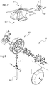
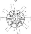
- FIGS. 7 to 9 illustrate examples of use of a torsion beam according to the invention.
- a torsionous beam can be arranged on a vehicle and in particular an aircraft 60.
- This aircraft 60 can be a rotorcraft, and for example a helicopter.
- the aircraft 60 may comprise at least one rotor, such as a rotor 61 mainly involved in the lift and / or propulsion of the aircraft and a rotor participating at least in controlling the yaw movement of the aircraft.
- a rotor 61 mainly involved in the lift and / or propulsion of the aircraft and a rotor participating at least in controlling the yaw movement of the aircraft.
- torsion beams according to the invention can be arranged on a rotor for connecting a blade to a hub.
- the figure 8 illustrates a torsion beam according to the figure 1 to be fixed to a blade 64 and to a hub 63.
- the figure 9 illustrates a set 55 of torsion beams connected to blades 64.
Landscapes
- Engineering & Computer Science (AREA)
- Mechanical Engineering (AREA)
- Aviation & Aerospace Engineering (AREA)
- Springs (AREA)
- Structures Of Non-Positive Displacement Pumps (AREA)
- Turbine Rotor Nozzle Sealing (AREA)
Priority Applications (1)
| Application Number | Priority Date | Filing Date | Title |
|---|---|---|---|
| PL17195369T PL3315403T3 (pl) | 2016-10-31 | 2017-10-09 | Belka skrętna dla łopaty, zespół belek skrętnych, wirnik i statek powietrzny |
Applications Claiming Priority (1)
| Application Number | Priority Date | Filing Date | Title |
|---|---|---|---|
| FR1601561A FR3058126B1 (fr) | 2016-10-31 | 2016-10-31 | Faisceau torsible pour pale, un ensemble de faisceaux torsibles, un rotor et un aeronef |
Publications (2)
| Publication Number | Publication Date |
|---|---|
| EP3315403A1 EP3315403A1 (fr) | 2018-05-02 |
| EP3315403B1 true EP3315403B1 (fr) | 2019-04-17 |
Family
ID=58314289
Family Applications (1)
| Application Number | Title | Priority Date | Filing Date |
|---|---|---|---|
| EP17195369.8A Active EP3315403B1 (fr) | 2016-10-31 | 2017-10-09 | Faisceau torsible pour pale, un ensemble de faisceaux torsibles, un rotor et un aeronef |
Country Status (4)
| Country | Link |
|---|---|
| EP (1) | EP3315403B1 (pl) |
| CA (1) | CA2982070C (pl) |
| FR (1) | FR3058126B1 (pl) |
| PL (1) | PL3315403T3 (pl) |
Cited By (1)
| Publication number | Priority date | Publication date | Assignee | Title |
|---|---|---|---|---|
| RU2808319C1 (ru) * | 2020-05-06 | 2023-11-28 | коптер груп аг | Работающий на растяжение и кручение торсион головки винта винтокрылого летательного аппарата |
Families Citing this family (4)
| Publication number | Priority date | Publication date | Assignee | Title |
|---|---|---|---|---|
| CH717387A1 (de) | 2020-05-06 | 2021-11-15 | Kopter Group Ag | Zug- und Torsionsband eines Rotorkopfes eines Drehflügelflugzeugs. |
| CH717385A1 (de) | 2020-05-06 | 2021-11-15 | Kopter Group Ag | Heckrotorkopf eines ummantelten Heckrotors eines Drehflügelflugzeugs und Blatthalterung. |
| US11440651B1 (en) | 2021-03-01 | 2022-09-13 | Textron Innovations Inc. | Spherical bearing centrifugal force retention link |
| CH721967A2 (de) * | 2024-07-08 | 2026-01-15 | Kopter Group Ag | Rotornabe für einen Heckrotor eines Drehflüglers und Drehflügler mit einer Rotornabe |
Family Cites Families (5)
| Publication number | Priority date | Publication date | Assignee | Title |
|---|---|---|---|---|
| FR1543858A (fr) * | 1967-07-15 | 1968-10-25 | Bolkow Gmbh | Rotor pour aéronefs à voilure tournante |
| JP2003322138A (ja) * | 2002-04-30 | 2003-11-14 | Ntn Corp | コンロッドおよび軸受付きコンロッド |
| EP2246259B1 (en) * | 2009-04-29 | 2012-12-12 | Eurocopter Deutschland GmbH | Rotor wing with integrated tension-torque-transmission element and method for its production |
| EP2246256B1 (en) * | 2009-04-29 | 2012-10-24 | Eurocopter Deutschland GmbH | Tension-torque-transmission element for a fenestron blade and method for producing it |
| US8662847B2 (en) * | 2010-10-11 | 2014-03-04 | Eurocopter Deutschland Gmbh | Rotor blade with control tube |
-
2016
- 2016-10-31 FR FR1601561A patent/FR3058126B1/fr not_active Expired - Fee Related
-
2017
- 2017-10-09 EP EP17195369.8A patent/EP3315403B1/fr active Active
- 2017-10-09 PL PL17195369T patent/PL3315403T3/pl unknown
- 2017-10-10 CA CA2982070A patent/CA2982070C/fr active Active
Cited By (2)
| Publication number | Priority date | Publication date | Assignee | Title |
|---|---|---|---|---|
| RU2808319C1 (ru) * | 2020-05-06 | 2023-11-28 | коптер груп аг | Работающий на растяжение и кручение торсион головки винта винтокрылого летательного аппарата |
| RU2818281C1 (ru) * | 2020-05-06 | 2024-04-27 | коптер груп аг | Головка хвостового винта винтокрылого летательного аппарата и держатель лопасти |
Also Published As
| Publication number | Publication date |
|---|---|
| PL3315403T3 (pl) | 2019-09-30 |
| CA2982070C (fr) | 2018-12-04 |
| CA2982070A1 (fr) | 2017-12-13 |
| FR3058126A1 (fr) | 2018-05-04 |
| EP3315403A1 (fr) | 2018-05-02 |
| FR3058126B1 (fr) | 2019-03-29 |
Similar Documents
| Publication | Publication Date | Title |
|---|---|---|
| EP3315403B1 (fr) | Faisceau torsible pour pale, un ensemble de faisceaux torsibles, un rotor et un aeronef | |
| EP0604299B1 (fr) | Dispositif de liaison pale-moyeu à attache feuilletée, pale de rotor munie d'une telle attache,et rotor équipé de telles pales | |
| EP2504176B1 (fr) | Roue composite, notamment pour un cycle, et procede de fabrication d'une telle roue | |
| EP0080920B1 (fr) | Rotor pour giravions, à articulations intégrées dans le pied de pale | |
| EP2137065B1 (fr) | Dispositif de fixation d'un organe de sustentation au fuselage d'un avion | |
| WO2011001050A1 (fr) | Element de fuselage comportant un troncon de fuselage et des moyens de jonction | |
| EP2070819B1 (fr) | Pale de giravion, rotor de giravion muni de ladite pale, et procédé de fabrication de cette pale | |
| EP1614622B1 (fr) | Plancher de cockpit pour aéronef | |
| EP2783989B1 (fr) | Mât déployable à déploiement spontané autonome et satellite comportant au moins un tel mât | |
| FR3059298A1 (fr) | Ensemble pour aeronef comprenant un moteur de type " open rotor puller " et des moyens d'accrochage de celui-ci a la structure rigide d'un mat d'accrochage | |
| CA2914699A1 (fr) | Pivot de pale d'helice aerienne en forme de calotte spherique | |
| EP2818408B1 (fr) | Pale à rigidité en torsion réduite et rotor muni d'une telle pale | |
| EP3699091B1 (fr) | Structure primaire d'un mât d'aéronef comportant au moins un renfort transversal équipé de deux bielles disposées en diagonale et aéronef comprenant une telle structure primaire | |
| FR2719552A1 (fr) | Aube de redresseur pour dispositif anti-couple à rotor et stator redresseur carénés d'hélicoptère. | |
| CA1332053C (fr) | Mat-moyeu integre et tete de rotor de giravion le comportant | |
| FR2855811A1 (fr) | Pale de rotor a pas variable, pour rotors carenes, notamment d'helicopteres | |
| FR3030445A1 (fr) | Helice pour turbomachine d'aeronef, comprenant une structure de retention de pales raccordee a l'extremite radiale externe de chaque pale | |
| EP1571082A1 (fr) | Système de montage interposé entre un moteur d'aéronef et une structure rigide d'un mât d'accrochage fixé sous une voilure de cet aéronef | |
| CA2714815C (fr) | Dispositif anticouple d'un giravion | |
| FR3061246A1 (fr) | Dispositif de cerclage | |
| FR2766157A1 (fr) | Dispositif de protection thermique d'organes elastomeriques, ensemble de tels dispositifs pour la protection par temps froid d'un rotor de giravion, et rotor de giravion equipe d'un tel ensemble | |
| FR2648106A1 (fr) | Dispositif de butees escamotables pour pales de rotors de giravions, et tete de rotor le comportant | |
| EP4039589A1 (fr) | Systeme carene et aeronef | |
| FR2898581A1 (fr) | Pale comportant une manchette integree et rotor de giravion pourvu d'une telle pale. | |
| EP3999789A1 (fr) | Tirant pour structure notamment en treillis |
Legal Events
| Date | Code | Title | Description |
|---|---|---|---|
| PUAI | Public reference made under article 153(3) epc to a published international application that has entered the european phase |
Free format text: ORIGINAL CODE: 0009012 |
|
| STAA | Information on the status of an ep patent application or granted ep patent |
Free format text: STATUS: THE APPLICATION HAS BEEN PUBLISHED |
|
| AK | Designated contracting states |
Kind code of ref document: A1 Designated state(s): AL AT BE BG CH CY CZ DE DK EE ES FI FR GB GR HR HU IE IS IT LI LT LU LV MC MK MT NL NO PL PT RO RS SE SI SK SM TR |
|
| AX | Request for extension of the european patent |
Extension state: BA ME |
|
| STAA | Information on the status of an ep patent application or granted ep patent |
Free format text: STATUS: REQUEST FOR EXAMINATION WAS MADE |
|
| 17P | Request for examination filed |
Effective date: 20180629 |
|
| RBV | Designated contracting states (corrected) |
Designated state(s): AL AT BE BG CH CY CZ DE DK EE ES FI FR GB GR HR HU IE IS IT LI LT LU LV MC MK MT NL NO PL PT RO RS SE SI SK SM TR |
|
| GRAP | Despatch of communication of intention to grant a patent |
Free format text: ORIGINAL CODE: EPIDOSNIGR1 |
|
| STAA | Information on the status of an ep patent application or granted ep patent |
Free format text: STATUS: GRANT OF PATENT IS INTENDED |
|
| RIC1 | Information provided on ipc code assigned before grant |
Ipc: B64C 27/33 20060101AFI20181102BHEP Ipc: B64C 27/473 20060101ALI20181102BHEP |
|
| INTG | Intention to grant announced |
Effective date: 20181206 |
|
| GRAS | Grant fee paid |
Free format text: ORIGINAL CODE: EPIDOSNIGR3 |
|
| GRAA | (expected) grant |
Free format text: ORIGINAL CODE: 0009210 |
|
| STAA | Information on the status of an ep patent application or granted ep patent |
Free format text: STATUS: THE PATENT HAS BEEN GRANTED |
|
| AK | Designated contracting states |
Kind code of ref document: B1 Designated state(s): AL AT BE BG CH CY CZ DE DK EE ES FI FR GB GR HR HU IE IS IT LI LT LU LV MC MK MT NL NO PL PT RO RS SE SI SK SM TR |
|
| REG | Reference to a national code |
Ref country code: GB Ref legal event code: FG4D Free format text: NOT ENGLISH |
|
| REG | Reference to a national code |
Ref country code: CH Ref legal event code: EP |
|
| REG | Reference to a national code |
Ref country code: DE Ref legal event code: R096 Ref document number: 602017003352 Country of ref document: DE |
|
| REG | Reference to a national code |
Ref country code: AT Ref legal event code: REF Ref document number: 1121266 Country of ref document: AT Kind code of ref document: T Effective date: 20190515 Ref country code: IE Ref legal event code: FG4D Free format text: LANGUAGE OF EP DOCUMENT: FRENCH |
|
| REG | Reference to a national code |
Ref country code: NL Ref legal event code: MP Effective date: 20190417 |
|
| REG | Reference to a national code |
Ref country code: LT Ref legal event code: MG4D |
|
| PG25 | Lapsed in a contracting state [announced via postgrant information from national office to epo] |
Ref country code: NL Free format text: LAPSE BECAUSE OF FAILURE TO SUBMIT A TRANSLATION OF THE DESCRIPTION OR TO PAY THE FEE WITHIN THE PRESCRIBED TIME-LIMIT Effective date: 20190417 |
|
| PG25 | Lapsed in a contracting state [announced via postgrant information from national office to epo] |
Ref country code: ES Free format text: LAPSE BECAUSE OF FAILURE TO SUBMIT A TRANSLATION OF THE DESCRIPTION OR TO PAY THE FEE WITHIN THE PRESCRIBED TIME-LIMIT Effective date: 20190417 Ref country code: PT Free format text: LAPSE BECAUSE OF FAILURE TO SUBMIT A TRANSLATION OF THE DESCRIPTION OR TO PAY THE FEE WITHIN THE PRESCRIBED TIME-LIMIT Effective date: 20190817 Ref country code: AL Free format text: LAPSE BECAUSE OF FAILURE TO SUBMIT A TRANSLATION OF THE DESCRIPTION OR TO PAY THE FEE WITHIN THE PRESCRIBED TIME-LIMIT Effective date: 20190417 Ref country code: HR Free format text: LAPSE BECAUSE OF FAILURE TO SUBMIT A TRANSLATION OF THE DESCRIPTION OR TO PAY THE FEE WITHIN THE PRESCRIBED TIME-LIMIT Effective date: 20190417 Ref country code: SE Free format text: LAPSE BECAUSE OF FAILURE TO SUBMIT A TRANSLATION OF THE DESCRIPTION OR TO PAY THE FEE WITHIN THE PRESCRIBED TIME-LIMIT Effective date: 20190417 Ref country code: FI Free format text: LAPSE BECAUSE OF FAILURE TO SUBMIT A TRANSLATION OF THE DESCRIPTION OR TO PAY THE FEE WITHIN THE PRESCRIBED TIME-LIMIT Effective date: 20190417 Ref country code: NO Free format text: LAPSE BECAUSE OF FAILURE TO SUBMIT A TRANSLATION OF THE DESCRIPTION OR TO PAY THE FEE WITHIN THE PRESCRIBED TIME-LIMIT Effective date: 20190717 Ref country code: LT Free format text: LAPSE BECAUSE OF FAILURE TO SUBMIT A TRANSLATION OF THE DESCRIPTION OR TO PAY THE FEE WITHIN THE PRESCRIBED TIME-LIMIT Effective date: 20190417 |
|
| PG25 | Lapsed in a contracting state [announced via postgrant information from national office to epo] |
Ref country code: LV Free format text: LAPSE BECAUSE OF FAILURE TO SUBMIT A TRANSLATION OF THE DESCRIPTION OR TO PAY THE FEE WITHIN THE PRESCRIBED TIME-LIMIT Effective date: 20190417 Ref country code: GR Free format text: LAPSE BECAUSE OF FAILURE TO SUBMIT A TRANSLATION OF THE DESCRIPTION OR TO PAY THE FEE WITHIN THE PRESCRIBED TIME-LIMIT Effective date: 20190718 Ref country code: BG Free format text: LAPSE BECAUSE OF FAILURE TO SUBMIT A TRANSLATION OF THE DESCRIPTION OR TO PAY THE FEE WITHIN THE PRESCRIBED TIME-LIMIT Effective date: 20190717 Ref country code: RS Free format text: LAPSE BECAUSE OF FAILURE TO SUBMIT A TRANSLATION OF THE DESCRIPTION OR TO PAY THE FEE WITHIN THE PRESCRIBED TIME-LIMIT Effective date: 20190417 |
|
| REG | Reference to a national code |
Ref country code: AT Ref legal event code: MK05 Ref document number: 1121266 Country of ref document: AT Kind code of ref document: T Effective date: 20190417 |
|
| PG25 | Lapsed in a contracting state [announced via postgrant information from national office to epo] |
Ref country code: IS Free format text: LAPSE BECAUSE OF FAILURE TO SUBMIT A TRANSLATION OF THE DESCRIPTION OR TO PAY THE FEE WITHIN THE PRESCRIBED TIME-LIMIT Effective date: 20190817 |
|
| REG | Reference to a national code |
Ref country code: DE Ref legal event code: R097 Ref document number: 602017003352 Country of ref document: DE |
|
| PG25 | Lapsed in a contracting state [announced via postgrant information from national office to epo] |
Ref country code: DK Free format text: LAPSE BECAUSE OF FAILURE TO SUBMIT A TRANSLATION OF THE DESCRIPTION OR TO PAY THE FEE WITHIN THE PRESCRIBED TIME-LIMIT Effective date: 20190417 Ref country code: AT Free format text: LAPSE BECAUSE OF FAILURE TO SUBMIT A TRANSLATION OF THE DESCRIPTION OR TO PAY THE FEE WITHIN THE PRESCRIBED TIME-LIMIT Effective date: 20190417 Ref country code: SK Free format text: LAPSE BECAUSE OF FAILURE TO SUBMIT A TRANSLATION OF THE DESCRIPTION OR TO PAY THE FEE WITHIN THE PRESCRIBED TIME-LIMIT Effective date: 20190417 Ref country code: EE Free format text: LAPSE BECAUSE OF FAILURE TO SUBMIT A TRANSLATION OF THE DESCRIPTION OR TO PAY THE FEE WITHIN THE PRESCRIBED TIME-LIMIT Effective date: 20190417 Ref country code: RO Free format text: LAPSE BECAUSE OF FAILURE TO SUBMIT A TRANSLATION OF THE DESCRIPTION OR TO PAY THE FEE WITHIN THE PRESCRIBED TIME-LIMIT Effective date: 20190417 Ref country code: CZ Free format text: LAPSE BECAUSE OF FAILURE TO SUBMIT A TRANSLATION OF THE DESCRIPTION OR TO PAY THE FEE WITHIN THE PRESCRIBED TIME-LIMIT Effective date: 20190417 |
|
| PLBE | No opposition filed within time limit |
Free format text: ORIGINAL CODE: 0009261 |
|
| STAA | Information on the status of an ep patent application or granted ep patent |
Free format text: STATUS: NO OPPOSITION FILED WITHIN TIME LIMIT |
|
| PG25 | Lapsed in a contracting state [announced via postgrant information from national office to epo] |
Ref country code: SM Free format text: LAPSE BECAUSE OF FAILURE TO SUBMIT A TRANSLATION OF THE DESCRIPTION OR TO PAY THE FEE WITHIN THE PRESCRIBED TIME-LIMIT Effective date: 20190417 |
|
| 26N | No opposition filed |
Effective date: 20200120 |
|
| PG25 | Lapsed in a contracting state [announced via postgrant information from national office to epo] |
Ref country code: TR Free format text: LAPSE BECAUSE OF FAILURE TO SUBMIT A TRANSLATION OF THE DESCRIPTION OR TO PAY THE FEE WITHIN THE PRESCRIBED TIME-LIMIT Effective date: 20190417 |
|
| REG | Reference to a national code |
Ref country code: DE Ref legal event code: R119 Ref document number: 602017003352 Country of ref document: DE |
|
| PG25 | Lapsed in a contracting state [announced via postgrant information from national office to epo] |
Ref country code: SI Free format text: LAPSE BECAUSE OF FAILURE TO SUBMIT A TRANSLATION OF THE DESCRIPTION OR TO PAY THE FEE WITHIN THE PRESCRIBED TIME-LIMIT Effective date: 20190417 Ref country code: MC Free format text: LAPSE BECAUSE OF FAILURE TO SUBMIT A TRANSLATION OF THE DESCRIPTION OR TO PAY THE FEE WITHIN THE PRESCRIBED TIME-LIMIT Effective date: 20190417 |
|
| PG25 | Lapsed in a contracting state [announced via postgrant information from national office to epo] |
Ref country code: LU Free format text: LAPSE BECAUSE OF NON-PAYMENT OF DUE FEES Effective date: 20191009 Ref country code: DE Free format text: LAPSE BECAUSE OF NON-PAYMENT OF DUE FEES Effective date: 20200501 |
|
| REG | Reference to a national code |
Ref country code: BE Ref legal event code: MM Effective date: 20191031 |
|
| PG25 | Lapsed in a contracting state [announced via postgrant information from national office to epo] |
Ref country code: BE Free format text: LAPSE BECAUSE OF NON-PAYMENT OF DUE FEES Effective date: 20191031 |
|
| PG25 | Lapsed in a contracting state [announced via postgrant information from national office to epo] |
Ref country code: IE Free format text: LAPSE BECAUSE OF NON-PAYMENT OF DUE FEES Effective date: 20191009 |
|
| PG25 | Lapsed in a contracting state [announced via postgrant information from national office to epo] |
Ref country code: CY Free format text: LAPSE BECAUSE OF FAILURE TO SUBMIT A TRANSLATION OF THE DESCRIPTION OR TO PAY THE FEE WITHIN THE PRESCRIBED TIME-LIMIT Effective date: 20190417 |
|
| PG25 | Lapsed in a contracting state [announced via postgrant information from national office to epo] |
Ref country code: MT Free format text: LAPSE BECAUSE OF FAILURE TO SUBMIT A TRANSLATION OF THE DESCRIPTION OR TO PAY THE FEE WITHIN THE PRESCRIBED TIME-LIMIT Effective date: 20190417 Ref country code: HU Free format text: LAPSE BECAUSE OF FAILURE TO SUBMIT A TRANSLATION OF THE DESCRIPTION OR TO PAY THE FEE WITHIN THE PRESCRIBED TIME-LIMIT; INVALID AB INITIO Effective date: 20171009 |
|
| GBPC | Gb: european patent ceased through non-payment of renewal fee |
Effective date: 20211009 |
|
| PG25 | Lapsed in a contracting state [announced via postgrant information from national office to epo] |
Ref country code: MK Free format text: LAPSE BECAUSE OF FAILURE TO SUBMIT A TRANSLATION OF THE DESCRIPTION OR TO PAY THE FEE WITHIN THE PRESCRIBED TIME-LIMIT Effective date: 20190417 |
|
| PG25 | Lapsed in a contracting state [announced via postgrant information from national office to epo] |
Ref country code: GB Free format text: LAPSE BECAUSE OF NON-PAYMENT OF DUE FEES Effective date: 20211009 |
|
| P01 | Opt-out of the competence of the unified patent court (upc) registered |
Effective date: 20230530 |
|
| PGFP | Annual fee paid to national office [announced via postgrant information from national office to epo] |
Ref country code: PL Payment date: 20250926 Year of fee payment: 9 |
|
| REG | Reference to a national code |
Ref country code: CH Ref legal event code: U11 Free format text: ST27 STATUS EVENT CODE: U-0-0-U10-U11 (AS PROVIDED BY THE NATIONAL OFFICE) Effective date: 20251101 |
|
| PGFP | Annual fee paid to national office [announced via postgrant information from national office to epo] |
Ref country code: IT Payment date: 20251024 Year of fee payment: 9 |
|
| PGFP | Annual fee paid to national office [announced via postgrant information from national office to epo] |
Ref country code: FR Payment date: 20251030 Year of fee payment: 9 |
|
| PGFP | Annual fee paid to national office [announced via postgrant information from national office to epo] |
Ref country code: CH Payment date: 20251101 Year of fee payment: 9 |