EP3315392A1 - Storage for two-wheel-vehicles - Google Patents
Storage for two-wheel-vehicles Download PDFInfo
- Publication number
- EP3315392A1 EP3315392A1 EP16195525.7A EP16195525A EP3315392A1 EP 3315392 A1 EP3315392 A1 EP 3315392A1 EP 16195525 A EP16195525 A EP 16195525A EP 3315392 A1 EP3315392 A1 EP 3315392A1
- Authority
- EP
- European Patent Office
- Prior art keywords
- storage system
- container
- storage
- storage area
- vehicles
- Prior art date
- Legal status (The legal status is an assumption and is not a legal conclusion. Google has not performed a legal analysis and makes no representation as to the accuracy of the status listed.)
- Granted
Links
Images


Classifications
-
- B—PERFORMING OPERATIONS; TRANSPORTING
- B62—LAND VEHICLES FOR TRAVELLING OTHERWISE THAN ON RAILS
- B62H—CYCLE STANDS; SUPPORTS OR HOLDERS FOR PARKING OR STORING CYCLES; APPLIANCES PREVENTING OR INDICATING UNAUTHORIZED USE OR THEFT OF CYCLES; LOCKS INTEGRAL WITH CYCLES; DEVICES FOR LEARNING TO RIDE CYCLES
- B62H3/00—Separate supports or holders for parking or storing cycles
- B62H3/08—Separate supports or holders for parking or storing cycles involving recesses or channelled rails for embracing the bottom part of a wheel
-
- E—FIXED CONSTRUCTIONS
- E04—BUILDING
- E04H—BUILDINGS OR LIKE STRUCTURES FOR PARTICULAR PURPOSES; SWIMMING OR SPLASH BATHS OR POOLS; MASTS; FENCING; TENTS OR CANOPIES, IN GENERAL
- E04H6/00—Buildings for parking cars, rolling-stock, aircraft, vessels or like vehicles, e.g. garages
- E04H6/005—Garages for vehicles on two wheels
Definitions
- the fan has a heating and / or a cooling and / or a drying unit. If, for example, only one heater is provided, the system can, for example, in addition to the dryer function by the air exchange ensure that the batteries of electric bicycles are not stored in too cold ambient air. This is especially true when a charging function is realized with a planned.
- the door 45 On the rear wall 64 opposite side of the container 60, the door 45 is arranged, which represents a further closable side wall of the container 60.
- the container has no lid in this embodiment.
- the door 45 has a plurality of through holes 72, which allows air circulation.
- the bottom is provided as a perforated bottom plate 65 which is closed on the side wall 61 opposite side with a side rail 66.
- a plurality of bottom grid openings 71 on the bottom plate 65 at least one and here two receiving grooves 67 for wheels of second wheels, especially bicycles 75 are provided which can be advanced on the groove 67 until they are clamped in a corresponding receiving bracket 68 become.
- the power supply within the storage system 1 is also provided with the units 80 which are provided in the upper portion of the rear opening 43 on the horizontal stand 20. These are blower units that face forward and slightly down to blow airflow over parked vehicles 75. In a simple exemplary embodiment, this may simply be a fan that moves ambient air, with air being able to exit through the door grille openings 72 at the front and below the floor after passing through the floor openings 71. Thus, a dryer function is achieved, especially when wet or wet two-wheelers are set. On the side wall 61 hooks (not shown) can be provided, on which rain gliders, helmets, gloves, etc. can be hung.
- the reference numeral 70 is a stack frame member is provided, which element advantageously comprises an eyelet, so that a number of loading and unloading stations 40 can be raised en bloc and staggered, which allows a simple structure. In particular, there is a possibility for stackability as later in connection with Fig. 5 described.
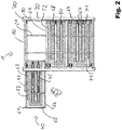
- the Fig. 2 shows a schematic plan view of a storage system 1 of Fig. 1 , Identical or similar features are provided in all representations with the same or similar reference numerals.
- the Fig. 3 shows a schematic perspective view of a storage system 1 according to another embodiment of the invention, without top cover and with a control panel 55.
- six loading and unloading stations 40 are arranged side by side, with two containers 60 are open.
- Various containers side by side are separated by continuous side walls 26, in others behind behind the rear wall 64 openings 43, wherein in the upper region above the rear wall 64 each have a dryer unit 80 is mounted, which are aligned in the container interior.
- the container 60 are provided only for a two-wheeler.
- the charging port 63 may be provided in the lower back panel 73.
- the control unit 55 may comprise an input and display unit 59, in which the loading station and unloading station 40 to be opened is selected, and where appropriate, a payment terminal is integrated.
- the doors 145 are integrated as a front wall in the container 60 and have a handle 46 for pulling out of the container 60.
- the Fig. 4 shows an enlarged section of one Fig. 3 similar storage system 1, wherein the individual containers 60 are laterally separated by the inner side walls 26. Since here also the doors 145 are configured as solid doors, the air is guided through below the floor 65 air extraction systems from the container 60 dissipate. Therefore, the inner side walls 26 advantageously do not extend to a possible lower horizontal frame 20 but at least in the bottom 65 in order to achieve a corresponding air movement with little air resistance can.
- the control unit 55 may comprise temperature sensors with which the reaching and falling below or exceeding predetermined threshold values can be determined, such that the heating function or the cooling function is switchable.
- the temperature sensors can also be arranged in the storage area at different locations, in particular per container, in order to control the fans more accurately.
- the control unit may then alternatively include an emergency shutdown when an unusual high temperature is detected in a container when charging the battery of an electric bicycle.
Landscapes
- Engineering & Computer Science (AREA)
- Architecture (AREA)
- Mechanical Engineering (AREA)
- Civil Engineering (AREA)
- Structural Engineering (AREA)
- Devices That Are Associated With Refrigeration Equipment (AREA)
Abstract
Ein Aufbewahrungssystem für Fahrzeuge, insbesondere von Zweirädern, Fahrrädern oder Motorrädern, hat ein im wesentlichen geschlossenes Gehäuse (10, 20, 30, 25, 45) mit einem von aussen nicht zugänglichen Aufbewahrungsbereich (60) und mindestens eine verschliessbare Be- und Entladestation (40) der Fahrzeuge, wobei der Aufbewahrungsbereich (60) mit mindestens einem Gebläse (79) versehen ist, mit dem die Luft in dem Aufbewahrungsbereich (60) austauschbar ist, um die eingestellten Fahrzeuge zu trocknen und/oder die Umgebungstemperatur in einem vorbestimmten Temperaturbande zu halten.A storage system for vehicles, in particular of two-wheelers, bicycles or motorcycles, has a substantially closed housing (10, 20, 30, 25, 45) with a storage area (60) not accessible from the outside and at least one lockable loading and unloading station (40 ) of the vehicles, wherein the storage area (60) is provided with at least one fan (79) with which the air in the storage area (60) is interchangeable to dry the parked vehicles and / or maintain the ambient temperature within a predetermined temperature range ,
Description
Die vorliegende Erfindung betrifft ein Aufbewahrungssystem für Fahrzeuge, insbesondere für Zweiräder, Fahrräder oder Motorräder.The present invention relates to a storage system for vehicles, especially for two-wheelers, bicycles or motorcycles.
Bei herkömmlichen Aufbewahrungssystemen für Fahrzeuge, insbesondere für Zweiräder, Fahrräder oder Motorräder, werden die Fahrzeuge einzeln oder gemeinsam in einem Aufbewahrungsbereich aufbewahrt.In conventional storage systems for vehicles, especially for two-wheelers, bicycles or motorcycles, the vehicles are stored individually or together in a storage area.
Die
Die
Die
Es ist daher eine Aufgabe der Erfindung ein Aufbewahrungssystem für Fahrzeuge, insbesondere für Zweiräder, Fahrräder oder Motorräder zur Verfügung zu stellen, welche die aus dem Stand der Technik bekannten Nachteile vermeidet.It is therefore an object of the invention to provide a storage system for vehicles, especially for two-wheelers, bicycles or motorcycles, which avoids the disadvantages known from the prior art.
Diese Aufgabe wird durch ein Aufbewahrungssystem mit den Merkmalen des Anspruchs 1 gelöst.This object is achieved by a storage system having the features of
Ein Aufbewahrungssystem für Fahrzeuge, insbesondere von Zweirädern, Fahrrädern oder Motorrädern, hat ein im wesentlichen geschlossenes Gehäuse mit einem von aussen nicht zugänglichen Aufbewahrungsbereich und mindestens eine verschliessbare Be- und Entladestation der Fahrzeuge, wobei der Aufbewahrungsbereich mit mindestens einem Gebläse versehen ist, mit dem die Luft in dem Aufbewahrungsbereich austauschbar ist, um die eingestellten Fahrzeuge zu trocknen und/oder die Umgebungstemperatur in einem vorbestimmten Temperaturbande zu halten.A storage system for vehicles, in particular of two-wheelers, bicycles or motorcycles, has a substantially closed housing with a storage area not accessible from the outside and at least one lockable loading and unloading station of the vehicles, wherein the storage area is provided with at least one fan with which the Air in the storage area is interchangeable to dry the set vehicles and / or to keep the ambient temperature in a predetermined Temperaturbande.
Vorteilhafterweise hat das Gebläse eine Heizungs- und/oder eine Kühlungs- und/oder eine Trocknungseinheit. Sofern z.B. nur eine Heizung vorgesehen ist, kann das System beispielsweise neben der Trocknerfunktion durch den Luftaustausch sicherstellen, dass die Akkumulatoren von Elektrofahrädern nicht in einer zu kalten Umgebungsluft gelagert werden. Das gilt insbesondere, wenn eine Ladefunktion mit einem vorgesehenen realisiert ist.Advantageously, the fan has a heating and / or a cooling and / or a drying unit. If, for example, only one heater is provided, the system can, for example, in addition to the dryer function by the air exchange ensure that the batteries of electric bicycles are not stored in too cold ambient air. This is especially true when a charging function is realized with a planned.
Der Aufbewahrungsbereich ist vorteilhafterweise in eine Vielzahl von Behältern aufgeteilt, welche im wesentlichen die Form eines Quaders aufweisen und mindestens durch einen Boden und durch Seitenwände und Vorder- und/oder Rückwände zumindest teilweise geschlossen sind. Dabei ist jedem Behälter zusätzlich eine am Rahmen angeordnete verschliessbare Tür zugeordnet, mit welcher eine weitere Seite zumindest teilweise verschliessbar ist. Die Tür kann dann Durchgänge für die besagte Luftzirkulation aufweisen.The storage area is advantageously divided into a plurality of containers, which have substantially the shape of a cuboid and at least partially closed by a bottom and by side walls and front and / or rear walls. In this case, each container is additionally assigned a lockable door arranged on the frame, with which a further side can be closed at least partially. The door may then have passageways for said air circulation.
Jeder Behälter kann auch zumindest teilweise aus dem Aufbewahrungssystem ausfahrbar sein, um die Zweiräder leicht einzustellen und herauszunehmen.Each container may also be at least partially extendable from the storage system to easily adjust and remove the two-wheeler.
Der Boden der Behälter kann insbesondere eine Lochplatte sein, wobei unterhalb der Lochplatte sich ein Hohlraum zur Ableitung von durch das Gebläse hindurchgeblasene Luft befindet.The bottom of the container may in particular be a perforated plate, wherein below the perforated plate is a cavity for the discharge of air blown through the fan.
Jeder Behälter kann mindestens einen nach innen ausgerichteten elektrischen Anschluss aufweist, an welchem ein elektrisches Gerät durch einen Benutzer anschliessbar ist. Damit ist insbesondere ein elektrischer Speicher für ein Fahrzeug mit einem Elektroantrieb an dem nach innen ausgerichteten elektrischen Anschluss anschliessbar.Each container may have at least one inwardly directed electrical connection to which an electrical device can be connected by a user. Thus, in particular, an electrical memory for a vehicle with an electric drive can be connected to the inwardly directed electrical connection.
In dem Aufbewahrungsbereich ist vorteilhafterweise mindestens ein Temperatursensor vorgesehen, der mit einer Kontrolleinheit für die Gebläse verbunden ist, wobei die Kontrolleinheit ausgestaltet ist, um bei Unterschreiten eines vorbestimmten Schwellwertes für die Temperatur eine Heizungsfunktion für mindestens ein Gebläse angeschaltet wird, und/oder um bei Überschreiten eines vorbestimmten Schwellwertes für die Temperatur eine Kühlfunktion für mindestens ein Gebläse angeschaltet wird. Dabei kann in mehreren oder in jedem Behälter ein solcher Temperatursensor vorgesehen sein, der mit der Kontrolleinheit für die Gebläse verbunden ist, wobei die Kontrolleinheit ausgestaltet ist, um bei Unterschreiten bzw. Überschreiten des vorbestimmten Schwellwertes für die Temperatur die den Temperatursensoren zugeordneten Gebläse einzuschalten.In the storage area, at least one temperature sensor is advantageously provided, which is connected to a control unit for the blower, wherein the control unit is designed to turn on below a predetermined threshold for the temperature, a heating function for at least one blower, and / or at exceeding a predetermined threshold value for the temperature, a cooling function for at least one fan is turned on. In this case, such a temperature sensor may be provided in several or in each container, which is connected to the control unit for the blower, wherein the control unit is designed to turn on when the temperature falls below the predetermined threshold value for the temperature associated with the blower.
Weitere Ausführungsformen sind in den abhängigen Ansprüchen angegeben.Further embodiments are given in the dependent claims.
Bevorzugte Ausführungsformen der Erfindung werden im Folgenden anhand der Zeichnungen beschrieben, die lediglich zur Erläuterung dienen und nicht einschränkend auszulegen sind. In den Zeichnungen zeigen:
- Fig. 1
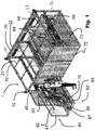
- eine schematische perspektivische Ansicht eines Aufbewahrungssystems gemäss einem Ausführungsbeispiel der Erfindung,
- Fig. 2
- eine schematische Draufsicht auf ein Aufbewahrungssystem der
Fig. 1 , - Fig. 3
- eine schematische perspektivische Ansicht eines Aufbewahrungssystems gemäss einem weiteren Ausführungsbeispiel der Erfindung, ohne obere Abdeckelemente und mit einer Steuerkonsole,
- Fig. 4
- einen vergrösserten Ausschnitt aus
Fig. 3 , und - Fig. 5
- eine schematische perspektivische Ansicht eines Aufbewahrungssystems gemäss einem weiteren Ausführungsbeispiel der Erfindung mit zwei Etagen.
- Fig. 1
- a schematic perspective view of a storage system according to an embodiment of the invention,
- Fig. 2
- a schematic plan view of a storage system of
Fig. 1 . - Fig. 3
- a schematic perspective view of a storage system according to another embodiment of the invention, without top cover and with a control panel,
- Fig. 4
- an enlarged section
Fig. 3 , and - Fig. 5
- a schematic perspective view of a storage system according to another embodiment of the invention with two floors.
Die
Dabei ist für eine der drei Einheiten ein ausgefahrener Behälter 60 einer Belade- und Entladestation 40 dargestellt. Eine diese Anlage steuernde Kontrolleinheit 55 ist hier nicht dargestellt worden. Um den Behälter 60 ausfahren zu können, muss die Tür 45 der Belade- und Entladestation 40 vorab geöffnet werden. Dies kann mittels eines herkömmlichen Schiebetorantriebes oder manuell über einen Handgriff 46 (in anderen Ausführungsbeispielen) realisiert sein.In this case, an
Ein solches Ausfahrsystem gewährleistet ein zuverlässiges und stabiles Ein- und Ausfahren des Behälters 60 aus dem Aufbewahrungssystem 1. Dafür weist der abgebildete Behälter 60 einen Boden 65, eine Rückwand 64 und mindestens eine an der Rückwand 64 seitlich anschliessende Seitenwand 61 auf, welche zumindest teilweise geschlossenen sind. Es ist in den verschiedenen Ausführungsbeispielen zu sehen, dass insbesondere an den Seitenwänden zum Teil innere Seitenwände 26 vorgesehen sind, zum Teil Durchbrüche 42, die nebeneinander liegende Behälter 60 strömungstechnisch miteinander verbinden. Dabei kann ein solcher Durchbruch zum Beispiel durch einen (in den Figuren nicht dargestellten) Maschendraht gesichert sein. Das gleiche gilt für die Rückwand 64, die einen hinteren Durchbruch 64 aufweist, der zu einer eventuell dahinter angeordneten zweiten entgegengesetzten Reihe von Behältern 60 führt.Such an extension system ensures a reliable and stable retraction and retraction of the
Auf der der Rückwand 64 gegenüberliegenden Seite des Behälters 60 ist die Tür 45 angeordnet, welche eine weitere verschliessbare Seitenwand des Behälters 60 darstellt. Der Behälter weist in dieser Ausführungsform keinen Deckel auf. Die Tür 45 verfügt über eine Vielzahl von Durchbohrungen 72, die eine Luftzirkulation ermöglicht.On the
In dem Behälter 60 ist der Boden als gelochte Bodenplatte 65 vorgesehen, der auf der der Seitenwand 61 gegenüberliegenden Seite mit einer Seitenschiene 66 abgeschlossen ist. Damit bestehen in der Bodenplatte 65 eine Vielzahl von Bodengitteröffnungen 71 Auf der Bodenplatte 65 sind mindestens eine und hier zwei Aufnahmerillen 67 für Räder von Zweitädern, insbesondere Fahrräder 75 vorgesehen, die auf der Rille 67 vorgeschoben werden können, bis sie in eine entsprechende Aufnahmeklammer 68 eingeklemmt werden.In the
Das Aufbewahrungssystem der
Es ist somit im Innern des Behälters 60 jeweils mindesten ein elektrischer Anschluss 63 vorgesehen. Der Anschluss 63 kann eine Steckdose aufweisen, welche es erlaubt, gängige Stecker anzuschliessen. Alternativ oder zusätzlich kann der Anschluss 63 ein Kabel (nicht dargestellt) aufweisen, welches derart ausgestaltet ist, dass es innerhalb des Behälters 60 führbar ist und ebenfalls das Verbinden mit gängigen Steckern oder elektrischen Speichern oder Elektrofahrzeugen erlaubt. Um die Relativbewegung zwischen Behälterkörper und Rahmengerüst 10 aufzunehmen, ist eine flexible Verbindung, beispielsweise in der Form eines Kabelschlepps, zwischen dem elektrischen Anschluss am Rahmen und dem Anschluss 63 im Behälterinnern vorgesehen.Thus, at least one
Die Stromversorgung innerhalb des Aufbewahrungssystems 1 ist ebenfalls noch mit den Einheiten 80 versehen, die im oberen Abschnitts des hinteren Durchbruchs 43 am horizontalen Gerüst 20 vorgesehen sind. Dabei handelt es sich um Gebläseeinheiten, die nach vorne und leicht nach unten gerichtet sind, um einen Luftstrom über eingestellte Fahrzeuge 75 zu blasen. Dabei kann es sich in einem einfachen Ausführungsbeispiel einfach um ein Gebläse handeln, dass Umgebungsluft bewegt, wobei Luft vorne durch die Türgitteröffnungen 72 und unten unter dem Boden nach Durchtritt durch die Bodenöffnungen 71 austreten kann. Damit wird eine Trocknerfunktion erreicht, insbesondere wenn feuchte oder nasse Zweiräder eingestellt werden. An der Seitenwand 61 können (nicht dargestellt) Haken vorgesehen sein, an denen Regenpelerine, Helme, Handschuhe, etc. aufgehängt werden können.The power supply within the
In weiteren Ausführungsbeispielen, bei denen die Aufbewahrungssysteme insbesondere draussen aufgestellt werden, können die Einheiten 80 auch Heizungselemente enthalten, zum einen, um die Luftfeuchtigkeit im Behälterraum 60 abzusenken, aber insbesondere, damit eingestellte Akkumulatoren von Elektrofahrrädern nicht zu kalt gelagert werden, insbesondere wenn sie gleichzeitig aufgeladen werden. Auf der anderen Seite können die Einheiten 80, gerade auch, wenn das Aufbewahrungssystem 1 draussen steht, Kühlelemente enthalten, um ein Überhitzen der aufladenden Akkumulatoren und Batterien von Elektrofahrrädern zu vermeiden.In further embodiments, in which the storage systems are placed in particular outside, the
Mit dem Bezugszeichen 70 ist ein Stapelrahmenelement versehen, welches Element vorteilhafterweise eine Öse umfasst, so dass eine Reihe von Be- und Entladestationen 40 en bloc angehoben und versetzt werden können, was einen einfachen Aufbau gestattet. Insbesondere ergibt sich eine Möglichkeit zur Stapelbarkeit wie später im Zusammenhang mit
Die
Die
Die
Die
Der modulare Aufbau des Systems gestattet es, dass horizontale und vertikale Transporteinheiten beliebig miteinander kombinierbar sind. Alternativ zu den in der
Sofern die Gebläse 79 eine Heizungsfunktion (für die kalte Jahreszeit) und/oder eine Kühlfunktion (für den Sommer) umfassen, kann die Kontrolleinheit 55 Temperatursensoren aufweisen, mit denen das Erreichen und Unterschreiten bzw. Überschreiten von vorbestimmten Schwellwerten feststellbar ist, so dass die Heizungsfunktion bzw. die Kühlfunktion zuschaltbar ist. Die Temperatursensoren können auch im Aufbewahrungsbereich an verschiedenen Orten angeordnet sein, insbesondere je Behälter vorgesehen sein, um die Gebläse genauer anzusteuern. Die Kontrolleinheit kann dann auch alternativ eine Notabschaltung umfassen, wenn beim Aufladen der Batterie eines Elektrofahrrads eine unübliche hohe Temperatur in einem Behälter festgestellt wird.
Claims (11)
Priority Applications (1)
| Application Number | Priority Date | Filing Date | Title |
|---|---|---|---|
| EP16195525.7A EP3315392B1 (en) | 2016-10-25 | 2016-10-25 | Storage system for two-wheel-vehicles |
Applications Claiming Priority (1)
| Application Number | Priority Date | Filing Date | Title |
|---|---|---|---|
| EP16195525.7A EP3315392B1 (en) | 2016-10-25 | 2016-10-25 | Storage system for two-wheel-vehicles |
Publications (2)
| Publication Number | Publication Date |
|---|---|
| EP3315392A1 true EP3315392A1 (en) | 2018-05-02 |
| EP3315392B1 EP3315392B1 (en) | 2020-05-06 |
Family
ID=57208145
Family Applications (1)
| Application Number | Title | Priority Date | Filing Date |
|---|---|---|---|
| EP16195525.7A Active EP3315392B1 (en) | 2016-10-25 | 2016-10-25 | Storage system for two-wheel-vehicles |
Country Status (1)
| Country | Link |
|---|---|
| EP (1) | EP3315392B1 (en) |
Cited By (3)
| Publication number | Priority date | Publication date | Assignee | Title |
|---|---|---|---|---|
| IT201800007806A1 (en) * | 2018-08-03 | 2020-02-03 | Mach 1 Srl | APPARATUS FOR THE RECOVERY OF VEHICLES SUCH AS BICYCLES, MOTORCYCLES OR MOPEDS |
| IT201800010703A1 (en) * | 2018-11-29 | 2020-05-29 | Martina Alice Spinoglio | Ciclorimessa for storing cycles, system for storing cycles and related control method |
| CN113404345A (en) * | 2021-07-30 | 2021-09-17 | 河南理工大学 | Three-dimensional intelligent charging garage for electric vehicles |
Citations (9)
| Publication number | Priority date | Publication date | Assignee | Title |
|---|---|---|---|---|
| DE9311296U1 (en) * | 1993-07-29 | 1993-10-07 | Eggers, Michael, 24558 Henstedt-Ulzburg | Device for storing a large number of bicycles |
| AT397405B (en) * | 1991-11-29 | 1994-04-25 | Glas Gerhard | Container for storing bicycles |
| DE29514276U1 (en) * | 1995-07-08 | 1996-01-04 | Hohrenk jun., Ernst, 38162 Cremlingen | Storage facility for two-wheelers, in particular for bicycles |
| US5845788A (en) | 1997-03-19 | 1998-12-08 | Rhc/Spacemaster Corporation | Bicycle storage and display system |
| DE20209448U1 (en) * | 2002-06-13 | 2002-08-29 | Bauer, Michael, 63776 Mömbris | two-wheeler garage |
| WO2007029026A1 (en) | 2005-09-08 | 2007-03-15 | Nigel William Sharp | Storage system |
| US20090107056A1 (en) * | 2007-10-30 | 2009-04-30 | Victor Kirilichin | Vehicle Storage and Display Enclosure |
| US20100204823A1 (en) | 2009-02-08 | 2010-08-12 | Perry North | Automated bike parking system |
| DE102009028211A1 (en) * | 2009-08-04 | 2011-02-17 | Anja Schmidt-Amelung | Fixed storage dispenser for use in rental system for bicycle or bicycle additional device, particularly bicycle with electric drive, has retaining device for retaining bicycle or bicycle additional device |
-
2016
- 2016-10-25 EP EP16195525.7A patent/EP3315392B1/en active Active
Patent Citations (9)
| Publication number | Priority date | Publication date | Assignee | Title |
|---|---|---|---|---|
| AT397405B (en) * | 1991-11-29 | 1994-04-25 | Glas Gerhard | Container for storing bicycles |
| DE9311296U1 (en) * | 1993-07-29 | 1993-10-07 | Eggers, Michael, 24558 Henstedt-Ulzburg | Device for storing a large number of bicycles |
| DE29514276U1 (en) * | 1995-07-08 | 1996-01-04 | Hohrenk jun., Ernst, 38162 Cremlingen | Storage facility for two-wheelers, in particular for bicycles |
| US5845788A (en) | 1997-03-19 | 1998-12-08 | Rhc/Spacemaster Corporation | Bicycle storage and display system |
| DE20209448U1 (en) * | 2002-06-13 | 2002-08-29 | Bauer, Michael, 63776 Mömbris | two-wheeler garage |
| WO2007029026A1 (en) | 2005-09-08 | 2007-03-15 | Nigel William Sharp | Storage system |
| US20090107056A1 (en) * | 2007-10-30 | 2009-04-30 | Victor Kirilichin | Vehicle Storage and Display Enclosure |
| US20100204823A1 (en) | 2009-02-08 | 2010-08-12 | Perry North | Automated bike parking system |
| DE102009028211A1 (en) * | 2009-08-04 | 2011-02-17 | Anja Schmidt-Amelung | Fixed storage dispenser for use in rental system for bicycle or bicycle additional device, particularly bicycle with electric drive, has retaining device for retaining bicycle or bicycle additional device |
Cited By (3)
| Publication number | Priority date | Publication date | Assignee | Title |
|---|---|---|---|---|
| IT201800007806A1 (en) * | 2018-08-03 | 2020-02-03 | Mach 1 Srl | APPARATUS FOR THE RECOVERY OF VEHICLES SUCH AS BICYCLES, MOTORCYCLES OR MOPEDS |
| IT201800010703A1 (en) * | 2018-11-29 | 2020-05-29 | Martina Alice Spinoglio | Ciclorimessa for storing cycles, system for storing cycles and related control method |
| CN113404345A (en) * | 2021-07-30 | 2021-09-17 | 河南理工大学 | Three-dimensional intelligent charging garage for electric vehicles |
Also Published As
| Publication number | Publication date |
|---|---|
| EP3315392B1 (en) | 2020-05-06 |
Similar Documents
| Publication | Publication Date | Title |
|---|---|---|
| EP3085856B1 (en) | Storage system for vehicles | |
| EP2399309B1 (en) | Electrical power storage unit for motor vehicles | |
| EP3315392B1 (en) | Storage system for two-wheel-vehicles | |
| DE212013000184U1 (en) | Kit for a rack for functional training | |
| DE112014004921T5 (en) | System for rapid insertion and removal of a battery for vehicles | |
| DE60006506T2 (en) | BOX FOR ELECTRIC BATTERY UNIT | |
| DE102014112799A1 (en) | Charging station and method for producing a charging station | |
| DE102017005314A1 (en) | Energy storage arrangement and motor vehicle | |
| WO2019007730A1 (en) | Motor vehicle and method for arranging at least one traction energy storage device in a motor vehicle | |
| DE102018003491A1 (en) | As a portable container trained vending machine | |
| EP1375318A2 (en) | Sequential rack | |
| EP3988435B1 (en) | E-service module | |
| DE202011103341U1 (en) | Energy storage unit, energy storage unit housing and changing station for energy storage units | |
| DE202015103857U1 (en) | manufacturing facility | |
| DE202020003258U1 (en) | Multifunctional storage device | |
| DE102017005698B4 (en) | swap body | |
| DE102020004603A1 (en) | Multifunctional storage facility | |
| DE102020114553A1 (en) | Workshop trolley | |
| DE202015101314U1 (en) | Vehicle door for closing a cargo space and a transport vehicle with such a vehicle door | |
| DE202010008304U1 (en) | Porter with energy storage | |
| DE60201240T2 (en) | Cart for connecting to a module for air production by forced convection | |
| AT403497B (en) | STORAGE SYSTEM | |
| DE202020001306U1 (en) | Transportable, modular electric cooler | |
| DE102013002518A1 (en) | Closed encased and accessible mobile device for editing and ejecting honeycomb at different locations of transport vehicle, has transportable carrier frame which is positioned on base by suitable unit | |
| DE102022120790A1 (en) | Multi-walled battery housing with a hollow profile |
Legal Events
| Date | Code | Title | Description |
|---|---|---|---|
| PUAI | Public reference made under article 153(3) epc to a published international application that has entered the european phase |
Free format text: ORIGINAL CODE: 0009012 |
|
| STAA | Information on the status of an ep patent application or granted ep patent |
Free format text: STATUS: THE APPLICATION HAS BEEN PUBLISHED |
|
| AK | Designated contracting states |
Kind code of ref document: A1 Designated state(s): AL AT BE BG CH CY CZ DE DK EE ES FI FR GB GR HR HU IE IS IT LI LT LU LV MC MK MT NL NO PL PT RO RS SE SI SK SM TR |
|
| AX | Request for extension of the european patent |
Extension state: BA ME |
|
| STAA | Information on the status of an ep patent application or granted ep patent |
Free format text: STATUS: REQUEST FOR EXAMINATION WAS MADE |
|
| 17P | Request for examination filed |
Effective date: 20180903 |
|
| RBV | Designated contracting states (corrected) |
Designated state(s): AL AT BE BG CH CY CZ DE DK EE ES FI FR GB GR HR HU IE IS IT LI LT LU LV MC MK MT NL NO PL PT RO RS SE SI SK SM TR |
|
| GRAP | Despatch of communication of intention to grant a patent |
Free format text: ORIGINAL CODE: EPIDOSNIGR1 |
|
| STAA | Information on the status of an ep patent application or granted ep patent |
Free format text: STATUS: GRANT OF PATENT IS INTENDED |
|
| INTG | Intention to grant announced |
Effective date: 20200114 |
|
| GRAS | Grant fee paid |
Free format text: ORIGINAL CODE: EPIDOSNIGR3 |
|
| GRAA | (expected) grant |
Free format text: ORIGINAL CODE: 0009210 |
|
| STAA | Information on the status of an ep patent application or granted ep patent |
Free format text: STATUS: THE PATENT HAS BEEN GRANTED |
|
| AK | Designated contracting states |
Kind code of ref document: B1 Designated state(s): AL AT BE BG CH CY CZ DE DK EE ES FI FR GB GR HR HU IE IS IT LI LT LU LV MC MK MT NL NO PL PT RO RS SE SI SK SM TR |
|
| REG | Reference to a national code |
Ref country code: GB Ref legal event code: FG4D Free format text: NOT ENGLISH |
|
| REG | Reference to a national code |
Ref country code: CH Ref legal event code: EP Ref country code: AT Ref legal event code: REF Ref document number: 1266309 Country of ref document: AT Kind code of ref document: T Effective date: 20200515 |
|
| REG | Reference to a national code |
Ref country code: IE Ref legal event code: FG4D Free format text: LANGUAGE OF EP DOCUMENT: GERMAN |
|
| REG | Reference to a national code |
Ref country code: DE Ref legal event code: R096 Ref document number: 502016009838 Country of ref document: DE |
|
| REG | Reference to a national code |
Ref country code: CH Ref legal event code: NV Representative=s name: ISLER AND PEDRAZZINI AG, CH |
|
| REG | Reference to a national code |
Ref country code: LT Ref legal event code: MG4D |
|
| REG | Reference to a national code |
Ref country code: NL Ref legal event code: MP Effective date: 20200506 |
|
| PG25 | Lapsed in a contracting state [announced via postgrant information from national office to epo] |
Ref country code: GR Free format text: LAPSE BECAUSE OF FAILURE TO SUBMIT A TRANSLATION OF THE DESCRIPTION OR TO PAY THE FEE WITHIN THE PRESCRIBED TIME-LIMIT Effective date: 20200807 Ref country code: FI Free format text: LAPSE BECAUSE OF FAILURE TO SUBMIT A TRANSLATION OF THE DESCRIPTION OR TO PAY THE FEE WITHIN THE PRESCRIBED TIME-LIMIT Effective date: 20200506 Ref country code: NO Free format text: LAPSE BECAUSE OF FAILURE TO SUBMIT A TRANSLATION OF THE DESCRIPTION OR TO PAY THE FEE WITHIN THE PRESCRIBED TIME-LIMIT Effective date: 20200806 Ref country code: SE Free format text: LAPSE BECAUSE OF FAILURE TO SUBMIT A TRANSLATION OF THE DESCRIPTION OR TO PAY THE FEE WITHIN THE PRESCRIBED TIME-LIMIT Effective date: 20200506 Ref country code: IS Free format text: LAPSE BECAUSE OF FAILURE TO SUBMIT A TRANSLATION OF THE DESCRIPTION OR TO PAY THE FEE WITHIN THE PRESCRIBED TIME-LIMIT Effective date: 20200906 Ref country code: PT Free format text: LAPSE BECAUSE OF FAILURE TO SUBMIT A TRANSLATION OF THE DESCRIPTION OR TO PAY THE FEE WITHIN THE PRESCRIBED TIME-LIMIT Effective date: 20200907 Ref country code: LT Free format text: LAPSE BECAUSE OF FAILURE TO SUBMIT A TRANSLATION OF THE DESCRIPTION OR TO PAY THE FEE WITHIN THE PRESCRIBED TIME-LIMIT Effective date: 20200506 |
|
| PG25 | Lapsed in a contracting state [announced via postgrant information from national office to epo] |
Ref country code: LV Free format text: LAPSE BECAUSE OF FAILURE TO SUBMIT A TRANSLATION OF THE DESCRIPTION OR TO PAY THE FEE WITHIN THE PRESCRIBED TIME-LIMIT Effective date: 20200506 Ref country code: HR Free format text: LAPSE BECAUSE OF FAILURE TO SUBMIT A TRANSLATION OF THE DESCRIPTION OR TO PAY THE FEE WITHIN THE PRESCRIBED TIME-LIMIT Effective date: 20200506 Ref country code: RS Free format text: LAPSE BECAUSE OF FAILURE TO SUBMIT A TRANSLATION OF THE DESCRIPTION OR TO PAY THE FEE WITHIN THE PRESCRIBED TIME-LIMIT Effective date: 20200506 Ref country code: BG Free format text: LAPSE BECAUSE OF FAILURE TO SUBMIT A TRANSLATION OF THE DESCRIPTION OR TO PAY THE FEE WITHIN THE PRESCRIBED TIME-LIMIT Effective date: 20200806 |
|
| PG25 | Lapsed in a contracting state [announced via postgrant information from national office to epo] |
Ref country code: NL Free format text: LAPSE BECAUSE OF FAILURE TO SUBMIT A TRANSLATION OF THE DESCRIPTION OR TO PAY THE FEE WITHIN THE PRESCRIBED TIME-LIMIT Effective date: 20200506 Ref country code: AL Free format text: LAPSE BECAUSE OF FAILURE TO SUBMIT A TRANSLATION OF THE DESCRIPTION OR TO PAY THE FEE WITHIN THE PRESCRIBED TIME-LIMIT Effective date: 20200506 |
|
| PG25 | Lapsed in a contracting state [announced via postgrant information from national office to epo] |
Ref country code: CZ Free format text: LAPSE BECAUSE OF FAILURE TO SUBMIT A TRANSLATION OF THE DESCRIPTION OR TO PAY THE FEE WITHIN THE PRESCRIBED TIME-LIMIT Effective date: 20200506 Ref country code: RO Free format text: LAPSE BECAUSE OF FAILURE TO SUBMIT A TRANSLATION OF THE DESCRIPTION OR TO PAY THE FEE WITHIN THE PRESCRIBED TIME-LIMIT Effective date: 20200506 Ref country code: DK Free format text: LAPSE BECAUSE OF FAILURE TO SUBMIT A TRANSLATION OF THE DESCRIPTION OR TO PAY THE FEE WITHIN THE PRESCRIBED TIME-LIMIT Effective date: 20200506 Ref country code: SM Free format text: LAPSE BECAUSE OF FAILURE TO SUBMIT A TRANSLATION OF THE DESCRIPTION OR TO PAY THE FEE WITHIN THE PRESCRIBED TIME-LIMIT Effective date: 20200506 Ref country code: EE Free format text: LAPSE BECAUSE OF FAILURE TO SUBMIT A TRANSLATION OF THE DESCRIPTION OR TO PAY THE FEE WITHIN THE PRESCRIBED TIME-LIMIT Effective date: 20200506 Ref country code: ES Free format text: LAPSE BECAUSE OF FAILURE TO SUBMIT A TRANSLATION OF THE DESCRIPTION OR TO PAY THE FEE WITHIN THE PRESCRIBED TIME-LIMIT Effective date: 20200506 |
|
| PGFP | Annual fee paid to national office [announced via postgrant information from national office to epo] |
Ref country code: CH Payment date: 20201012 Year of fee payment: 5 Ref country code: IT Payment date: 20201022 Year of fee payment: 5 Ref country code: DE Payment date: 20201022 Year of fee payment: 5 |
|
| REG | Reference to a national code |
Ref country code: DE Ref legal event code: R097 Ref document number: 502016009838 Country of ref document: DE |
|
| PG25 | Lapsed in a contracting state [announced via postgrant information from national office to epo] |
Ref country code: SK Free format text: LAPSE BECAUSE OF FAILURE TO SUBMIT A TRANSLATION OF THE DESCRIPTION OR TO PAY THE FEE WITHIN THE PRESCRIBED TIME-LIMIT Effective date: 20200506 Ref country code: PL Free format text: LAPSE BECAUSE OF FAILURE TO SUBMIT A TRANSLATION OF THE DESCRIPTION OR TO PAY THE FEE WITHIN THE PRESCRIBED TIME-LIMIT Effective date: 20200506 |
|
| PLBE | No opposition filed within time limit |
Free format text: ORIGINAL CODE: 0009261 |
|
| STAA | Information on the status of an ep patent application or granted ep patent |
Free format text: STATUS: NO OPPOSITION FILED WITHIN TIME LIMIT |
|
| 26N | No opposition filed |
Effective date: 20210209 |
|
| PG25 | Lapsed in a contracting state [announced via postgrant information from national office to epo] |
Ref country code: SI Free format text: LAPSE BECAUSE OF FAILURE TO SUBMIT A TRANSLATION OF THE DESCRIPTION OR TO PAY THE FEE WITHIN THE PRESCRIBED TIME-LIMIT Effective date: 20200506 |
|
| GBPC | Gb: european patent ceased through non-payment of renewal fee |
Effective date: 20201025 |
|
| PG25 | Lapsed in a contracting state [announced via postgrant information from national office to epo] |
Ref country code: LU Free format text: LAPSE BECAUSE OF NON-PAYMENT OF DUE FEES Effective date: 20201025 Ref country code: MC Free format text: LAPSE BECAUSE OF FAILURE TO SUBMIT A TRANSLATION OF THE DESCRIPTION OR TO PAY THE FEE WITHIN THE PRESCRIBED TIME-LIMIT Effective date: 20200506 |
|
| REG | Reference to a national code |
Ref country code: BE Ref legal event code: MM Effective date: 20201031 |
|
| PG25 | Lapsed in a contracting state [announced via postgrant information from national office to epo] |
Ref country code: FR Free format text: LAPSE BECAUSE OF NON-PAYMENT OF DUE FEES Effective date: 20201031 |
|
| PG25 | Lapsed in a contracting state [announced via postgrant information from national office to epo] |
Ref country code: BE Free format text: LAPSE BECAUSE OF NON-PAYMENT OF DUE FEES Effective date: 20201031 Ref country code: GB Free format text: LAPSE BECAUSE OF NON-PAYMENT OF DUE FEES Effective date: 20201025 |
|
| PG25 | Lapsed in a contracting state [announced via postgrant information from national office to epo] |
Ref country code: IE Free format text: LAPSE BECAUSE OF NON-PAYMENT OF DUE FEES Effective date: 20201025 |
|
| REG | Reference to a national code |
Ref country code: DE Ref legal event code: R119 Ref document number: 502016009838 Country of ref document: DE |
|
| PG25 | Lapsed in a contracting state [announced via postgrant information from national office to epo] |
Ref country code: TR Free format text: LAPSE BECAUSE OF FAILURE TO SUBMIT A TRANSLATION OF THE DESCRIPTION OR TO PAY THE FEE WITHIN THE PRESCRIBED TIME-LIMIT Effective date: 20200506 Ref country code: MT Free format text: LAPSE BECAUSE OF FAILURE TO SUBMIT A TRANSLATION OF THE DESCRIPTION OR TO PAY THE FEE WITHIN THE PRESCRIBED TIME-LIMIT Effective date: 20200506 Ref country code: CY Free format text: LAPSE BECAUSE OF FAILURE TO SUBMIT A TRANSLATION OF THE DESCRIPTION OR TO PAY THE FEE WITHIN THE PRESCRIBED TIME-LIMIT Effective date: 20200506 |
|
| REG | Reference to a national code |
Ref country code: CH Ref legal event code: PL |
|
| PG25 | Lapsed in a contracting state [announced via postgrant information from national office to epo] |
Ref country code: MK Free format text: LAPSE BECAUSE OF FAILURE TO SUBMIT A TRANSLATION OF THE DESCRIPTION OR TO PAY THE FEE WITHIN THE PRESCRIBED TIME-LIMIT Effective date: 20200506 |
|
| PG25 | Lapsed in a contracting state [announced via postgrant information from national office to epo] |
Ref country code: DE Free format text: LAPSE BECAUSE OF NON-PAYMENT OF DUE FEES Effective date: 20220503 |
|
| PG25 | Lapsed in a contracting state [announced via postgrant information from national office to epo] |
Ref country code: LI Free format text: LAPSE BECAUSE OF NON-PAYMENT OF DUE FEES Effective date: 20211031 Ref country code: CH Free format text: LAPSE BECAUSE OF NON-PAYMENT OF DUE FEES Effective date: 20211031 |
|
| PG25 | Lapsed in a contracting state [announced via postgrant information from national office to epo] |
Ref country code: IT Free format text: LAPSE BECAUSE OF NON-PAYMENT OF DUE FEES Effective date: 20211025 |
|
| REG | Reference to a national code |
Ref country code: AT Ref legal event code: MM01 Ref document number: 1266309 Country of ref document: AT Kind code of ref document: T Effective date: 20211025 |
|
| PG25 | Lapsed in a contracting state [announced via postgrant information from national office to epo] |
Ref country code: AT Free format text: LAPSE BECAUSE OF NON-PAYMENT OF DUE FEES Effective date: 20211025 |