EP3315346A1 - Arbeitsgerät mit einem elektrischen antriebsmotor - Google Patents
Arbeitsgerät mit einem elektrischen antriebsmotor Download PDFInfo
- Publication number
- EP3315346A1 EP3315346A1 EP17001729.7A EP17001729A EP3315346A1 EP 3315346 A1 EP3315346 A1 EP 3315346A1 EP 17001729 A EP17001729 A EP 17001729A EP 3315346 A1 EP3315346 A1 EP 3315346A1
- Authority
- EP
- European Patent Office
- Prior art keywords
- drive motor
- power
- energy source
- electric drive
- energy
- Prior art date
- Legal status (The legal status is an assumption and is not a legal conclusion. Google has not performed a legal analysis and makes no representation as to the accuracy of the status listed.)
- Granted
Links
Images


Classifications
-
- B—PERFORMING OPERATIONS; TRANSPORTING
- B60—VEHICLES IN GENERAL
- B60L—PROPULSION OF ELECTRICALLY-PROPELLED VEHICLES; SUPPLYING ELECTRIC POWER FOR AUXILIARY EQUIPMENT OF ELECTRICALLY-PROPELLED VEHICLES; ELECTRODYNAMIC BRAKE SYSTEMS FOR VEHICLES IN GENERAL; MAGNETIC SUSPENSION OR LEVITATION FOR VEHICLES; MONITORING OPERATING VARIABLES OF ELECTRICALLY-PROPELLED VEHICLES; ELECTRIC SAFETY DEVICES FOR ELECTRICALLY-PROPELLED VEHICLES
- B60L1/00—Supplying electric power to auxiliary equipment of vehicles
- B60L1/003—Supplying electric power to auxiliary equipment of vehicles to auxiliary motors, e.g. for pumps, compressors
-
- B—PERFORMING OPERATIONS; TRANSPORTING
- B60—VEHICLES IN GENERAL
- B60L—PROPULSION OF ELECTRICALLY-PROPELLED VEHICLES; SUPPLYING ELECTRIC POWER FOR AUXILIARY EQUIPMENT OF ELECTRICALLY-PROPELLED VEHICLES; ELECTRODYNAMIC BRAKE SYSTEMS FOR VEHICLES IN GENERAL; MAGNETIC SUSPENSION OR LEVITATION FOR VEHICLES; MONITORING OPERATING VARIABLES OF ELECTRICALLY-PROPELLED VEHICLES; ELECTRIC SAFETY DEVICES FOR ELECTRICALLY-PROPELLED VEHICLES
- B60L1/00—Supplying electric power to auxiliary equipment of vehicles
- B60L1/20—Energy regeneration from auxiliary equipment
-
- B—PERFORMING OPERATIONS; TRANSPORTING
- B60—VEHICLES IN GENERAL
- B60L—PROPULSION OF ELECTRICALLY-PROPELLED VEHICLES; SUPPLYING ELECTRIC POWER FOR AUXILIARY EQUIPMENT OF ELECTRICALLY-PROPELLED VEHICLES; ELECTRODYNAMIC BRAKE SYSTEMS FOR VEHICLES IN GENERAL; MAGNETIC SUSPENSION OR LEVITATION FOR VEHICLES; MONITORING OPERATING VARIABLES OF ELECTRICALLY-PROPELLED VEHICLES; ELECTRIC SAFETY DEVICES FOR ELECTRICALLY-PROPELLED VEHICLES
- B60L50/00—Electric propulsion with power supplied within the vehicle
- B60L50/10—Electric propulsion with power supplied within the vehicle using propulsion power supplied by engine-driven generators, e.g. generators driven by combustion engines
- B60L50/15—Electric propulsion with power supplied within the vehicle using propulsion power supplied by engine-driven generators, e.g. generators driven by combustion engines with additional electric power supply
-
- B—PERFORMING OPERATIONS; TRANSPORTING
- B60—VEHICLES IN GENERAL
- B60L—PROPULSION OF ELECTRICALLY-PROPELLED VEHICLES; SUPPLYING ELECTRIC POWER FOR AUXILIARY EQUIPMENT OF ELECTRICALLY-PROPELLED VEHICLES; ELECTRODYNAMIC BRAKE SYSTEMS FOR VEHICLES IN GENERAL; MAGNETIC SUSPENSION OR LEVITATION FOR VEHICLES; MONITORING OPERATING VARIABLES OF ELECTRICALLY-PROPELLED VEHICLES; ELECTRIC SAFETY DEVICES FOR ELECTRICALLY-PROPELLED VEHICLES
- B60L50/00—Electric propulsion with power supplied within the vehicle
- B60L50/30—Electric propulsion with power supplied within the vehicle using propulsion power stored mechanically, e.g. in fly-wheels
-
- B—PERFORMING OPERATIONS; TRANSPORTING
- B60—VEHICLES IN GENERAL
- B60L—PROPULSION OF ELECTRICALLY-PROPELLED VEHICLES; SUPPLYING ELECTRIC POWER FOR AUXILIARY EQUIPMENT OF ELECTRICALLY-PROPELLED VEHICLES; ELECTRODYNAMIC BRAKE SYSTEMS FOR VEHICLES IN GENERAL; MAGNETIC SUSPENSION OR LEVITATION FOR VEHICLES; MONITORING OPERATING VARIABLES OF ELECTRICALLY-PROPELLED VEHICLES; ELECTRIC SAFETY DEVICES FOR ELECTRICALLY-PROPELLED VEHICLES
- B60L50/00—Electric propulsion with power supplied within the vehicle
- B60L50/40—Electric propulsion with power supplied within the vehicle using propulsion power supplied by capacitors
-
- B—PERFORMING OPERATIONS; TRANSPORTING
- B60—VEHICLES IN GENERAL
- B60L—PROPULSION OF ELECTRICALLY-PROPELLED VEHICLES; SUPPLYING ELECTRIC POWER FOR AUXILIARY EQUIPMENT OF ELECTRICALLY-PROPELLED VEHICLES; ELECTRODYNAMIC BRAKE SYSTEMS FOR VEHICLES IN GENERAL; MAGNETIC SUSPENSION OR LEVITATION FOR VEHICLES; MONITORING OPERATING VARIABLES OF ELECTRICALLY-PROPELLED VEHICLES; ELECTRIC SAFETY DEVICES FOR ELECTRICALLY-PROPELLED VEHICLES
- B60L50/00—Electric propulsion with power supplied within the vehicle
- B60L50/50—Electric propulsion with power supplied within the vehicle using propulsion power supplied by batteries or fuel cells
- B60L50/53—Electric propulsion with power supplied within the vehicle using propulsion power supplied by batteries or fuel cells in combination with an external power supply, e.g. from overhead contact lines
-
- B—PERFORMING OPERATIONS; TRANSPORTING
- B60—VEHICLES IN GENERAL
- B60L—PROPULSION OF ELECTRICALLY-PROPELLED VEHICLES; SUPPLYING ELECTRIC POWER FOR AUXILIARY EQUIPMENT OF ELECTRICALLY-PROPELLED VEHICLES; ELECTRODYNAMIC BRAKE SYSTEMS FOR VEHICLES IN GENERAL; MAGNETIC SUSPENSION OR LEVITATION FOR VEHICLES; MONITORING OPERATING VARIABLES OF ELECTRICALLY-PROPELLED VEHICLES; ELECTRIC SAFETY DEVICES FOR ELECTRICALLY-PROPELLED VEHICLES
- B60L2200/00—Type of vehicles
- B60L2200/40—Working vehicles
-
- Y—GENERAL TAGGING OF NEW TECHNOLOGICAL DEVELOPMENTS; GENERAL TAGGING OF CROSS-SECTIONAL TECHNOLOGIES SPANNING OVER SEVERAL SECTIONS OF THE IPC; TECHNICAL SUBJECTS COVERED BY FORMER USPC CROSS-REFERENCE ART COLLECTIONS [XRACs] AND DIGESTS
- Y02—TECHNOLOGIES OR APPLICATIONS FOR MITIGATION OR ADAPTATION AGAINST CLIMATE CHANGE
- Y02T—CLIMATE CHANGE MITIGATION TECHNOLOGIES RELATED TO TRANSPORTATION
- Y02T10/00—Road transport of goods or passengers
- Y02T10/60—Other road transportation technologies with climate change mitigation effect
- Y02T10/70—Energy storage systems for electromobility, e.g. batteries
-
- Y—GENERAL TAGGING OF NEW TECHNOLOGICAL DEVELOPMENTS; GENERAL TAGGING OF CROSS-SECTIONAL TECHNOLOGIES SPANNING OVER SEVERAL SECTIONS OF THE IPC; TECHNICAL SUBJECTS COVERED BY FORMER USPC CROSS-REFERENCE ART COLLECTIONS [XRACs] AND DIGESTS
- Y02—TECHNOLOGIES OR APPLICATIONS FOR MITIGATION OR ADAPTATION AGAINST CLIMATE CHANGE
- Y02T—CLIMATE CHANGE MITIGATION TECHNOLOGIES RELATED TO TRANSPORTATION
- Y02T10/00—Road transport of goods or passengers
- Y02T10/60—Other road transportation technologies with climate change mitigation effect
- Y02T10/7072—Electromobility specific charging systems or methods for batteries, ultracapacitors, supercapacitors or double-layer capacitors
Definitions
- the invention relates to a working device with an electric drive motor of the type specified in the preamble of claim 1.
- Such tools are used for the extraction of raw materials, for example as crushing machines and include a mechanical load such as an impact crusher or the like. And an electric drive motor.
- the electric drive motor is powered by an energy source and drives the mechanical consumer.
- the problem with such implements is the behavior of the electric drive motor during startup or when peak loads occur. Under such conditions, electric motors may require 2 to 2.5 times the electrical operating current needed in nominal load operation.
- connection Even with a connection of the electric drive motor of the implement to a public power grid, the connection must be designed for the high peak loads and is therefore expensive. In addition, a significant network load occurs at electrical power peaks. Such peak loads on the power grid can lead to higher power delivery costs for the operator of the implement.
- the invention has the object of providing a working device with an electric drive motor in such a way that the electric drive motor is economically designed for a given drive power and yet peak loads are covered above the given drive power.
- the electric drive motor of the working device according to the invention is supplied with a predetermined drive power from a first power source.
- a second energy source is provided, which in addition to the first drive motor provides a supplementary drive power available.
- the second energy source is intended to cover the power peaks of the electric drive motor above the drive power.
- the second energy source is designed as an energy store. The energy store is expedient to load from the first energy source.
- the electric drive motor When starting the electric drive motor of the mechanical load of the implement, the electric drive motor is powered from the first power source; From the energy storage, a supplementary drive power is additionally provided. The power peaks of the electric drive motor occurring in the starting operation of the mechanical load are covered by the energy storage above the drive power.
- an additional drive power can be provided from the energy store at occurring load peaks of the mechanical load.
- the energy storage device can be switched on mechanically or electrically to the electric drive motor.
- the drive power of the second energy source is switched to the drive motor via a switching device which is actuated as a function of the absorbed electric power of the drive motor.
- the energy storage of the second energy source covers during operation, the power peaks of the electric drive motor above the drive power.
- the first energy source does not have to cover significant power peaks of the electric drive motor either during start-up operation or during operation of the implement.
- the first energy source can be designed for nominal operation of the implement and therefore falls much smaller than in the prior art.
- An internal combustion engine for driving a generator as the first power source may have a smaller drive power and be operated with a high efficiency. When connected to a fixed voltage network as the first energy source peak currents can be avoided.
- the first energy source for the electric drive motor of the working device is a mobile generator.
- the generator is driven by an internal combustion engine, in particular a diesel engine.
- the implement can be operated detached from the public, fixed voltage network at any location.
- the first power source for the electric drive motor of the working device according to the invention is a public fixed voltage network.
- the first energy source for the electric drive motor is an optional switchable mobile generator or the public fixed voltage network.
- the energy storage of the second energy source is a mechanical energy storage, in particular a flywheel storage or the like.
- the short discharge times allow in seconds the delivery of high drive power and thus an immediate provision of additional drive power to power peaks of the electric drive motor above the drive power electrically, cover mechanically or hydraulically.
- the energy store of the second energy source can also be designed as a battery, rechargeable battery, high-performance rechargeable battery, high-performance condenser (ultra-capacitor) or the like. Particularly in the case of a high-performance battery or a high-performance capacitor, the recording or the delivery of very high power is ensured within the shortest possible time.
- connection of the second power source via an auxiliary motor mechanically.
- the drive motor and the auxiliary motor are connected to each other via a transmission.
- the switching device is controlled by an electrical system control with a computer unit.
- electrical drive motors, other electric motors and / or other small consumers are controlled in the implement and the power supply monitored by the system control.
- the switching device advantageously also controls the recuperation phases and the feed-in phases of the energy store.
- the implement comprises a chassis, which is driven in particular electrically or hydraulically.
- the chassis can in particular, be designed as a crawler undercarriage or as a chain drive.
- the implement can autonomously change the location at the site, without relying on the help of other towing vehicles.
- the chassis ensures mobility of the implement.
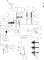
- Fig. 1 is a schematic block diagram of an embodiment of the working device 1 according to the invention shown.
- the implement 1 may be a working tool for crushing stones, wood or similar material.
- the implement 1 comprises an electric drive motor 2, a mechanical load 4, a first power source 5 and a second power source 6.
- the mechanical load in the embodiment is designed as an impact crusher.
- the impact crusher includes a rotor 22 having a diameter from Z. B. 1300 mm, at which at least three blow bars 45, in the exemplary embodiment four blow bars 45, are arranged.
- the rotor 22 is surrounded by a housing 46, which in the embodiment z. B. vertically above the rotor 22 has a horizontally extending inlet 43 and below the rotor 22 a z. B. vertical outlet 44 has.
- the rotor 22 is connected via a belt drive 47 to the electric drive motor 2.
- the belt drive comprises a flywheel 23, a V-belt pulley 25 and a V-belt 24, via which the flywheel 23 and the V-belt pulley 25 are connected.
- the flywheel 23 is mechanically connected to the rotor 22 and the V-belt pulley 25 to the electric drive motor 2.
- Non-uniformities occurring during operation, in particular higher-frequency nonuniformities due to the non-uniform loads of the mechanical load 4 are smoothed by the elastic properties of the belt drive 47 before reaching the electric drive motor 2.
- the first energy source 5 of the electric drive motor 2 may be a mobile generator 11 and / or a public fixed voltage network 10.
- the mobile generator 11 comprises a power generator 20, which is driven by an internal combustion engine 19, in particular a diesel engine.
- the working device 2 comprises a circuit 21, by which either the mobile generator 11 or the public, fixed voltage network as the first power source 5 are connected to the working device 2.
- the second energy source 6 is formed in the embodiment as an energy storage 8.
- the energy store 8 is, in particular, a mechanical energy store 12, which may preferably be designed as a flywheel store 13.
- the implement 2 has an electric machine 27 with frequency converter, which is mechanically connected to the flywheel 13.
- the flywheel storage 13 is charged or discharged via the electric machine 27 with frequency converter from the voltage network of the working device 2, the first power source 5.
- the implement 1 includes a brake chopper 28 which is electrically connected to the electric machine 27 connected to frequency converter. For example, in a discharge of the flywheel 13, the mains voltage of the implement 2 can be reduced before reaching an overvoltage and the excess energy in the network are converted by means of the brake chopper 28 via a braking resistor into thermal energy.
- the implement 1 expediently includes an auxiliary motor 14, a transmission 15 and a soft start device 29.
- the auxiliary motor 14 is connected to the electric drive motor 2 via the gear 15 and mechanical connections 26, 48.
- the auxiliary motor 14 can be powered by the first power source 5 and an intermediate soft start device 29, a rectifier in the embodiment, with energy.
- the auxiliary motor is connected via an electrical connection and via the electric machine with frequency converter 27 to the flywheel 13. Therefore, the flywheel storage 13 can be discharged from the auxiliary motor 14 or energized. If the flywheel storage is fed directly via the mobile generator 11 or the public fixed voltage network 10, the soft start device 29 is interposed in the embodiment so that when starting the flywheel 13 and when starting the auxiliary motor 14, an increased inrush current is avoided.
- the implement 1 has an electric chassis 18, which may be designed as a crawler undercarriage 31 or as an alternative tracked chassis.
- the chassis 18 includes electric machines with frequency converters 32 and drive gear 33, wherein on each drive side of the chassis at least one electric machine with frequency converter 32 and a drive gear 33 are arranged.
- the electric machines with frequency converter 32 are supplied in the embodiment of the second power source 6 with energy to cover the resulting in the movement of the implement load peaks.
- a supply of the chassis 18 with energy from the first power source 5 may be provided be.
- the electric machines with frequency converter 32 also DC motors can be used.
- the implement 1 includes a cooling system 30, which is in particular a liquid cooling system.
- a cooling system 30 which is in particular a liquid cooling system.
- the cooling system 30 all electric motors and / or electrical consumers or the like. Can be cooled.
- the implement 1 comprises an electrical system controller 16 with a switching device 9.
- the system controller 16 is advantageously controlled by a computer unit 17. Starting from the electrical system controller 16 expedient all provided in the implement 1 switching elements and electrical loads are monitored and in particular controlled.
- the implement 1 is preferably operated via the computer unit 17 according to the following method.
- the engine 19 of the power generator 20 is started from the standstill of the implement 1 out and set a corresponding operating speed.
- the power generator 20 can be connected via the clutch 49 to the engine 19 from the beginning or only when a predetermined speed of the engine 19 is reached. If the power generator 20 is switched on, the second energy source 6 can be supplied with energy via the soft-start device 29.
- the electric auxiliary motor 14 and the electric drive motor 2 are first decoupled via the electrical system control 16 from the first power source 5 and the second power source 6. If the flywheel accumulator 13 has converted and stored sufficient electrical energy from the first energy source 5 into mechanical energy via the electric machine with frequency converter 27, the electric drive motor 2 can be connected to the first energy source 5. At the same time, the from Flywheel accumulator 13 recorded mechanical energy via the electric machine with frequency converter 27 converted into electrical energy and the auxiliary motor 14 is provided. The auxiliary motor 14 converts the electrical energy from the second energy source 6 into mechanical energy, which is transmitted via the gear 15 and the mechanical connections 48 and 26 to the electric drive motor 2.
- a power peak 7 (FIG. Fig. 4 ), which is above a drive power 3 of the electric drive motor 2. Due to the additional power supply from the auxiliary motor 14, which is fed in particular mainly by the second power source 6, the power peak 7 can be covered above the drive power 3 of the electric drive motor 2 when starting the implement 1 without additional load on the electric drive motor 2.
- the impact crusher can be filled with stones or similar material to be crushed via the inlet 43.
- the crushed material contacts the blow bars 45 of the rotor 22 whose outer circumference is at least 25 m / s, and is thrown against the walls of the housing 46, so that the crushed material is crushed on impact.
- Load peaks can occur, for example, when the material to be crushed in the housing is so large that it wedges between the rotor 22 and the housing wall. With the breakage of the wedged crushing load decreases again. From such a peak load results in the electric drive motor 2, a power peak 7 ( Fig. 4 ), which can be covered by a supplementary drive power of the auxiliary motor 14 from the second power source 6.
- the auxiliary motor 14 can supply the mechanical drive power supplied by the electric drive motor 2 as electrical energy to the second energy source 6.
- the electrical energy generated by the auxiliary motor 14 is converted via the electric machine 27 with frequency converter and the flywheel storage 13 into mechanical energy and - stored in the flywheel storage.
- the second energy source 6 can also be fed electrically directly from the first energy source 5.
- a chassis 18 of the implement 1 which is hydraulically driven.
- the chassis 18 includes a clutch 40, at least two control pumps 35 and at least two hydraulic motors 34.
- the control pumps 35 are mechanically connected via the clutch 40 to the second power source 6, which drives the mechanical control pumps 35.
- the hydraulic motors 34 are driven by the control pumps 35.
- Each chassis side of the crawler chassis 31 is driven by a hydraulic motor 34 via a driving gear 33.
- the landing gear comprises a hydraulic pump 36, with which a pilot pressure is generated, and a hydraulic pump 37, which drives auxiliary hydraulic drives, such as a cylinder 41.
- a chassis 18 of the implement 1 which is hydraulically driven.
- the landing gear comprises a clutch 40, a pump 50, a control valve 39 and at least two hydraulic motors 34.
- the pump 50 is mechanically connected via the clutch 40 to the second power source 6, which the Pumps 50 mechanically drives.
- a control valve 39 is arranged, which regulates the required pressures on the hydraulic motors 34.
- Hydraulic auxiliary drives for example the cylinder 41, can be driven via the hydraulic pump 37.
- the hydraulic motor 37 can be driven hydraulically, alternatively also via an electric motor 38.
- Fig. 4 is a diagram showing the time course of the output power of the electric drive motor 2 of the implement 1.
- the energy supply is covered by a single energy source.
- the course of the output power is subject to high power fluctuations.
- the power source with a high drive power 42 is to be dimensioned.
- a second energy source 6 in the working device 1 enables a short-term provision of high additional drive power.
- the power peaks 7 can be covered.
- the first energy source 5 can be designed for a low drive power 3, which enables a more economical continuous operation of the implement 1.
- the second power source 6 is always charged from the first power source 5 when the electric drive motor 2 operates below a predetermined drive power.
Landscapes
- Engineering & Computer Science (AREA)
- Power Engineering (AREA)
- Transportation (AREA)
- Mechanical Engineering (AREA)
- Life Sciences & Earth Sciences (AREA)
- Sustainable Development (AREA)
- Sustainable Energy (AREA)
- Hybrid Electric Vehicles (AREA)
- Operation Control Of Excavators (AREA)
Abstract
Description
- Die Erfindung betrifft ein Arbeitsgerät mit einem elektrischen Antriebsmotor der im Oberbegriff des Anspruchs 1 angegebenen Gattung.
- Derartige Arbeitsgeräte werden zur Gewinnung von Rohstoffen, beispielsweise als Zerkleinerungsmaschinen eingesetzt und umfassen einen mechanischen Verbraucher beispielsweise einen Prallbrecher oder dgl. sowie einen elektrischen Antriebsmotor. Der elektrische Antriebsmotor wird über eine Energiequelle mit Energie versorgt und treibt den mechanischen Verbraucher an. Problematisch bei derartigen Arbeitsgeräten ist das Verhalten des elektrischen Antriebsmotors im Anfahrbetrieb oder beim Auftreten von Spitzenlasten. Unter solchen Bedingungen können Elektromotoren das 2- bis 2,5fache des elektrischen Betriebsstromes benötigen, der im Nennlastbetrieb benötigt wird.
- Bei der Versorgung des Antriebsmotors mit elektrischer Energie aus einem Generator sind dessen Verbrennungsmotor sowie der Generator selbst so ausgelegt, dass die erforderlichen Anlaufströme und die Spitzenlastströme mittels des Generators bereitgestellt werden können. Da der Generator auf die auftretenden Spitzenbelastungen auszulegen ist, ist er für den gewöhnlichen Nennlastbetrieb überdimensioniert und arbeitet daher oft nicht im Bereich eines optimalen Wirkungsgrades. Somit sind Kraftstoffverbrauch und die daraus resultierenden Betriebskosten erhöht. Eine Auslegung des Generators nach auftretenden Spitzenbelastungen hat auch einen entsprechend hohen Materialaufwand und hohe Investitionskosten zur Folge.
- Auch bei einem Anschluss des elektrischen Antriebsmotors des Arbeitsgerätes an ein öffentliches Stromnetz muss der Anschluss auf die hohen Spitzenbelastungen ausgelegt sein und ist daher aufwändig. Darüber hinaus tritt bei elektrischen Leistungsspitzen eine erhebliche Netzbelastung auf. Solche Spitzenbelastungen des Stromnetzes können zu höheren Strombereitstellungskosten für den Betreiber des Arbeitsgerätes führen.
- Arbeitsgeräte, deren elektrische Antriebsmotoren hohe Belastungsschwankungen im Anfahrbetrieb oder Belastungsspitzen im Arbeitsbetrieb aufweisen, sind konstruktiv stärker auszulegen und daher aufwändig.
- Der Erfindung liegt die Aufgabe zugrunde, ein Arbeitsgerät mit einem elektrischen Antriebsmotor derart weiterzubilden, dass der elektrische Antriebsmotor auf eine vorgegebene Antriebsleistung wirtschaftlich ausgelegt ist und dennoch Spitzenbelastungen oberhalb der vorgegebenen Antriebsleistung abgedeckt sind.
- Diese Aufgabe wird durch ein Arbeitsgerät mit den Merkmalen des Anspruchs 1 gelöst.
- Der elektrische Antriebsmotor des erfindungsgemäßen Arbeitsgeräts ist mit einer vorgegebenen Antriebsleistung aus einer ersten Energiequelle gespeist. Zur Abdeckung einer Spitzenlast ist eine zweite Energiequelle vorgesehen, die ergänzend zum ersten Antriebsmotor eine ergänzende Antriebsleistung zur Verfügung stellt. Die zweite Energiequelle ist dafür vorgesehen, die Leistungsspitzen des elektrischen Antriebsmotors oberhalb der Antriebsleistung abzudecken. Dabei ist die zweite Energiequelle als Energiespeicher ausgebildet. Der Energiespeicher ist zweckmäßig aus der ersten Energiequelle zu laden.
- Beim Anfahren des elektrischen Antriebsmotors des mechanischen Verbrauchers des Arbeitsgerätes ist der elektrische Antriebsmotor aus der ersten Energiequelle gespeist; aus dem Energiespeicher wird zusätzlich eine ergänzende Antriebsleistung bereitgestellt. Dabei werden die im Anfahrbetrieb des mechanischen Verbrauchers auftretenden Leistungsspitzen des elektrischen Antriebsmotors oberhalb der Antriebsleistung durch den Energiespeicher abgedeckt.
- Im Arbeitsbetrieb kann bei auftretenden Belastungsspitzen des mechanischen Verbrauchers eine zusätzliche Antriebsleistung aus dem Energiespeicher bereitgestellt werden. Der Energiespeicher kann dem elektrischen Antriebsmotor mechanisch oder elektrisch zugeschaltet werden. Hierzu wird die Antriebsleistung der zweiten Energiequelle über eine von der aufgenommenen elektrischen Leistung des Antriebsmotors abhängig betätigte Schalteinrichtung dem Antriebsmotor zugeschaltet. Der Energiespeicher der zweiten Energiequelle deckt dabei im Arbeitsbetrieb die Leistungsspitzen des elektrischen Antriebsmotors oberhalb der Antriebsleistung ab. Die erste Energiequelle muss weder im Anfahrbetrieb noch im Arbeitsbetrieb des Arbeitsgerätes signifikante Leistungsspitzen des elektrischen Antriebsmotors abdecken. Die erste Energiequelle kann für den Nennbetrieb des Arbeitsgerätes ausgelegt werden und fällt daher deutlich kleiner aus als im Stand der Technik. Ein Verbrennungsmotor zum Antrieb eines Generators als erste Energiequelle kann eine kleinere Antriebsleistung aufweisen und mit einem hohen Wirkungsgrad betrieben werden. Bei Anschluss an einem ortsfesten Spannungsnetz als erste Energiequelle können Spitzenströme vermieden werden.
- Vorteilhaft ist die erste Energiequelle für den elektrischen Antriebsmotor des erfindungsgemäßen Arbeitsgerätes ein mobiler Generator. Der Generator ist durch einen Verbrennungsmotor, insbesondere einen Dieselmotor, angetrieben. Dadurch kann das Arbeitsgerät losgelöst vom öffentlichen, ortsfesten Spannungsnetz an beliebigen Orten betrieben werden.
- Zweckmäßig ist die erste Energiequelle für den elektrischen Antriebsmotor des erfindungsgemäßen Arbeitsgerätes ein öffentliches ortsfestes Spannungsnetz.
- Alternativ ist die erste Energiequelle für den elektrischen Antriebsmotor ein wahlweise zuschaltbarer mobiler Generator oder das öffentliche, ortsfeste Spannungsnetz.
- In einer bevorzugten Ausführung der Erfindung ist der Energiespeicher der zweiten Energiequelle ein mechanischer Energiespeicher, insbesondere ein Schwungradspeicher oder dgl. Die kurzen Entladungszeiten ermöglichen in Sekunden die Abgabe hoher Antriebsleistungen und damit eine unmittelbare Bereitstellung zusätzlicher Antriebsleistung, um Leistungsspitzen des elektrischen Antriebsmotors oberhalb der Antriebsleistung elektrisch, mechanisch oder hydraulisch abzudecken. In Weiterbildung der Erfindung kann der Energiespeicher der zweiten Energiequelle auch als Batterie, Akku, Hochleistungsakku, Hochleistungskondensator (Ultrakondensator) oder dgl. ausgebildet sein. Insbesondere bei einem Hochleistungsakku oder bei einem Hochleistungskondensator ist innerhalb kürzester Zeit die Aufnahme bzw. die Abgabe einer sehr hohen Leistung gewährleistet.
- Vorteilhaft erfolgt das Zuschalten der zweiten Energiequelle über einen Hilfsmotor mechanisch. Zweckmäßig sind der Antriebsmotor und der Hilfsmotor über ein Getriebe miteinander verbunden.
- In Weiterbildung der Erfindung ist die Schalteinrichtung von einer elektrischen Anlagensteuerung mit einer Rechnereinheit gesteuert. Über die Anlagensteuerung werden insbesondere elektrische Antriebsmotoren, andere Elektromotoren und/oder andere Kleinverbraucher im Arbeitsgerät gesteuert sowie deren Energieversorgung überwacht. Weiter übernimmt die Schalteinrichtung das Zuschalten der verschiedenen Energiequellen, insbesondere der zweiten Energiequelle an den elektrischen Antriebsmotor des Arbeitsgerätes. Die Schalteinrichtung steuert vorteilhaft auch die Rekuperationsphasen und die Einspeisungsphasen des Energiespeichers.
- In vorteilhafter Weiterbildung der Erfindung umfasst das Arbeitsgerät ein Fahrwerk, welches insbesondere elektrisch oder hydraulisch angetrieben ist. Das Fahrwerk kann insbesondere auch als Raupenfahrwerk oder als Kettenantrieb ausgebildet sein. Mittels des Fahrwerkes kann das Arbeitsgerät am Einsatzort autark den Standort ändern, ohne auf die Hilfe anderer Zugfahrzeuge angewiesen zu sein. Durch das Fahrwerk wird eine Mobilität des Arbeitsgerätes gewährleistet.
- Weitere Merkmale der Erfindung ergeben sich aus den weiteren Ansprüchen, der Beschreibung und der Zeichnung, in der Ausführungsbeispiele der Erfindung dargestellt sind, die im Folgenden anhand der Zeichnung erläutert werden. Es zeigen:
- Fig. 1
- eine schematische Darstellung eines Blockschaltbildes eines Arbeitsgeräts,
- Fig. 2
- eine schematische Darstellung eines Blockschaltbildes eines hydraulischen Fahrwerks des Arbeitsgerätes nach
Fig. 1 , - Fig. 3
- eine schematische Darstellung eines Blockschaltbildes eines hydraulischen Fahrwerks nach
Fig. 2 mit einer Regelpumpe, - Fig. 4
- ein Diagramm über den zeitlichen Verlauf der Abtriebsleistung des elektrischen Antriebsmotors eines Arbeitsgerätes.
- In
Fig. 1 ist ein schematisches Blockschaltbild eines Ausführungsbeispiels des erfindungsgemäßen Arbeitsgerätes 1 gezeigt. Das Arbeitsgerät 1 kann ein Arbeitsgerät zum Zerkleinern von Steinen, Holz oder vergleichbarem Material sein. Das Arbeitsgerät 1 umfasst einen elektrischen Antriebsmotor 2, einen mechanischen Verbraucher 4, eine erste Energiequelle 5 und eine zweite Energiequelle 6. - Wie in
Fig. 1 gezeigt, ist der mechanische Verbraucher im Ausführungsbeispiel als ein Prallbrecher ausgeführt. Der Prallbrecher umfasst einen Rotor 22 mit einem Durchmesser von z. B. 1300 mm, an welchem mindestens drei Schlagleisten 45, im Ausführungsbeispiel vier Schlagleisten 45, angeordnet sind. Der Rotor 22 ist von einem Gehäuse 46 umgeben, welches im Ausführungsbeispiel z. B. vertikal oberhalb des Rotors 22 einen horizontal verlaufenden Einlass 43 und unterhalb des Rotors 22 einen z. B. vertikal verlaufenden Auslass 44 besitzt. Der Rotor 22 ist über einen Riementrieb 47 mit dem elektrischen Antriebsmotor 2 verbunden. Der Riementrieb umfasst eine Schwungscheibe 23, eine Keilriemenscheibe 25 und einen Keilriemen 24, über welchen die Schwungscheibe 23 und die Keilriemenscheibe 25 verbunden sind. Die Schwungscheibe 23 ist mit dem Rotor 22 und die Keilriemenscheibe 25 mit dem elektrischen Antriebsmotor 2 mechanisch verbunden. Im Betrieb auftretende Ungleichförmigkeiten, insbesondere höherfrequente Ungleichförmigkeiten aufgrund der ungleichförmigen Belastungen des mechanischen Verbrauchers 4 werden vor Erreichen des elektrischen Antriebsmotors 2 durch die elastischen Eigenschaften des Riementriebs 47 geglättet. - Wie in
Fig. 1 gezeigt, kann die erste Energiequelle 5 des elektrischen Antriebsmotors 2 ein mobiler Generator 11 und/oder ein öffentliches, ortsfestes Spannungsnetz 10 sein. Der mobile Generator 11 umfasst einen Stromgenerator 20, der von einem Verbrennungsmotor 19, insbesondere einem Dieselmotor angetrieben ist. Im Ausführungsbeispiel umfasst das Arbeitsgerät 2 eine Schaltung 21, durch welche entweder der mobile Generator 11 oder das öffentliche, ortsfeste Spannungsnetz als erste Energiequelle 5 dem Arbeitsgerät 2 zugeschaltet sind. - Die zweite Energiequelle 6 ist im Ausführungsbeispiel als ein Energiespeicher 8 ausgebildet. Der Energiespeicher 8 ist insbesondere ein mechanischer Energiespeicher 12, welcher vorzugsweise als Schwungradspeicher 13 ausgebildet sein kann. Das Arbeitsgerät 2 besitzt eine Elektromaschine 27 mit Frequenzumrichter, welche mit dem Schwungradspeicher 13 mechanisch verbunden ist. Der Schwungradspeicher 13 wird über die Elektromaschine 27 mit Frequenzumrichter aus dem Spannungsnetz des Arbeitsgerätes 2, der ersten Energiequelle 5, geladen oder entladen. Weiter umfasst das Arbeitsgerät 1 einen Bremschopper 28, welcher elektrisch mit der Elektromaschine 27 mit Frequenzumformer verbunden ist. Bei beispielsweise einem Entladevorgang des Schwungradspeichers 13 kann die Netzspannung des Arbeitsgerätes 2 noch vor Erreichen einer Überspannung reduziert werden und die überschüssige Energie im Netz mittels des Bremschoppers 28 über einen Bremswiderstand in thermische Energie umgewandelt werden.
- Wie in
Fig. 1 gezeigt, umfasst im Ausführungsbeispiel das Arbeitsgerät 1 zweckmäßig einen Hilfsmotor 14, ein Getriebe 15 und eine Sanftanlaufvorrichtung 29. Der Hilfsmotor 14 ist mit dem elektrischen Antriebsmotor 2 über das Getriebe 15 und mechanische Verbindungen 26, 48 verbunden. Der Hilfsmotor 14 kann über die erste Energiequelle 5 und eine zwischengeschaltete Sanftanlaufvorrichtung 29, im Ausführungsbeispiel ein Gleichrichter, mit Energie gespeist werden. Der Hilfsmotor ist über eine elektrische Verbindung und über die Elektromaschine mit Frequenzumformer 27 mit dem Schwungradspeicher 13 verbunden. Daher kann der Schwungradspeicher 13 vom Hilfsmotor 14 entladen oder mit Energie gespeist werden. Wird der Schwungradspeicher direkt über den mobilen Generator 11 oder das öffentliche, ortsfeste Spannungsnetz 10 gespeist, ist im Ausführungsbeispiel die Sanftanlaufvorrichtung 29 zwischengeschaltet, damit beim Anfahren des Schwungrades 13 sowie auch beim Anfahren des Hilfsmotors 14 ein erhöhter Einschaltstrom vermieden wird. - Im Ausführungsbeispiel nach
Fig. 1 besitzt das Arbeitsgerät 1 ein elektrisches Fahrwerk 18, welches als Raupenfahrwerk 31 oder als alternatives Kettenfahrwerk ausgebildet sein kann. Das Fahrwerk 18 umfasst Elektromaschinen mit Frequenzumformern 32 und Fahrgetriebe 33, wobei auf jeder Antriebsseite des Fahrwerkes mindestens eine Elektromaschine mit Frequenzumformer 32 und ein Fahrgetriebe 33 angeordnet sind. Die Elektromaschinen mit Frequenzumformer 32 sind im Ausführungsbeispiel von der zweiten Energiequelle 6 mit Energie versorgt, um die bei der Fortbewegung des Arbeitsgerätes entstehenden Belastungsspitzen abzudecken. Alternativ kann auch eine Versorgung des Fahrwerks 18 mit Energie von der ersten Energiequelle 5 vorgesehen sein. Anstelle der Elektromaschinen mit Frequenzumformer 32 können auch Gleichstrommotoren eingesetzt werden. - Im Ausführungsbeispiel enthält das Arbeitsgerät 1 ein Kühlsystem 30, welches insbesondere ein Flüssigkühlsystem ist. Mittels des Kühlsystems 30 können alle elektrischen Motoren und/oder elektrischen Verbraucher oder dgl. gekühlt werden.
- Das Arbeitsgerät 1 umfasst eine elektrische Anlagensteuerung 16 mit einer Schalteinrichtung 9. Die Anlagensteuerung 16 ist vorteilhaft von einer Rechnereinheit 17 gesteuert. Ausgehend von der elektrischen Anlagensteuerung 16 werden zweckmäßig alle im Arbeitsgerät 1 vorgesehenen Schaltelemente und elektrischen Verbraucher überwacht und insbesondere gesteuert.
- Das Arbeitsgerät 1 wird vorzugsweise über die Rechnereinheit 17 nach dem folgenden Verfahren betrieben.
- Im Ausführungsbeispiel wird aus dem Stillstand des Arbeitsgerätes 1 heraus der Verbrennungsmotor 19 des Stromgenerators 20 gestartet und eine entsprechende Betriebsdrehzahl eingestellt. Der Stromgenerator 20 kann über die Kupplung 49 dem Verbrennungsmotor 19 von Beginn an oder erst bei Erreichen einer vorgegebenen Drehzahl des Verbrennungsmotors 19 zugeschaltet werden. Ist der Stromgenerator 20 zugeschaltet, kann die zweite Energiequelle 6 über die Sanftanlaufvorrichtung 29 mit Energie versorgt werden.
- Der elektrische Hilfsmotor 14 sowie der elektrische Antriebsmotor 2 sind zunächst über die elektrische Anlagensteuerung 16 von der ersten Energiequelle 5 und der zweiten Energiequelle 6 entkoppelt. Hat der Schwungradspeicher 13 über die Elektromaschine mit Frequenzumformer 27 ausreichend elektrische Energie von der ersten Energiequelle 5 in mechanische Energie umgewandelt und gespeichert, kann der elektrische Antriebsmotor 2 der ersten Energiequelle 5 zugeschaltet werden. Zeitgleich wird die vom Schwungradspeicher 13 aufgenommene mechanische Energie über die Elektromaschine mit Frequenzumformer 27 in elektrische Energie umgewandelt und dem Hilfsmotor 14 zur Verfügung gestellt. Der Hilfsmotor 14 wandelt die elektrische Energie von der zweiten Energiequelle 6 in mechanische Energie um, welche über das Getriebe 15 und die mechanischen Verbindungen 48 und 26 an den elektrischen Antriebsmotor 2 übertragen wird.
- Beim Hochfahren des Rotors 22 über den Riementrieb 47 durch den elektrischen Antriebsmotor 2 entsteht eine Leistungsspitze 7 (
Fig. 4 ), die oberhalb einer Antriebsleistung 3 des elektrischen Antriebsmotors 2 liegt. Durch die zusätzliche Leistungszufuhr vom Hilfsmotor 14, welcher insbesondere vorwiegend durch die zweite Energiequelle 6 gespeist ist, kann die Leistungsspitze 7 oberhalb der Antriebsleistung 3 des elektrischen Antriebsmotors 2 beim Anfahren des Arbeitsgerätes 1 ohne zusätzliche Belastung des elektrischen Antriebsmotors 2 abgedeckt werden. - Hat der Rotor 22 die Betriebsdrehzahl erreicht, kann der Prallbrecher mit Steinen oder ähnlichem Brechgut über den Einlass 43 befüllt werden. Das Brechgut kontaktiert dabei die Schlagleisten 45 des Rotors 22, dessen Außenumfang eine Geschwindigkeit von mindestens 25 m/s beträgt, und wird an die Wände des Gehäuses 46 geschleudert, so dass das Brechgut beim Aufprall zertrümmert. Je höher die Drehgeschwindigkeit des Rotors 22 ist, desto kleiner ist das zertrümmerte Brechgut. Ist das Brechgut ausreichend klein zertrümmert, fällt es aus dem Auslass aus dem Gehäuse und kann über Förderbänder oder dgl. abtransportiert werden.
- Belastungsspitzen können beispielsweise dann auftreten, wenn das Brechgut im Gehäuse so groß ist, dass es sich zwischen Rotor 22 und Gehäusewand verkeilt. Mit dem Bruch des verkeilten Brechgutes nimmt die Belastung wieder ab. Aus einer solchen Belastungsspitze resultiert am elektrischen Antriebsmotor 2 eine Leistungsspitze 7 (
Fig. 4 ), welche über eine ergänzende Antriebsleistung des Hilfsmotors 14 aus der zweiten Energiequelle 6 abgedeckt werden kann. - Liegt die vom elektrischen Antriebsmotor 2 abgegebene Leistung unter der vorgegebenen Antriebsleistung 3, kann der elektrische Antriebsmotor 2 über das Getriebe 15 und die mechanischen Verbindungen 26, 48 den Hilfsmotor 14 antreiben. Der Hilfsmotor 14 kann im Generatorbetrieb die vom elektrischen Antriebsmotor 2 zugeführte mechanische Antriebsleistung als elektrische Energie der zweiten Energiequelle 6 zuführen. Die vom Hilfsmotor 14 generierte elektrische Energie wird über die Elektromaschine 27 mit Frequenzumformer und den Schwungradspeicher 13 in mechanische Energie umgewandelt und - im Schwungradspeicher - gespeichert.
- Wird der Rotor 22 mittels des elektrischen Antriebsmotors 2 unterhalb der vorgegebenen Antriebsleistung 3 betrieben, kann die zweite Energiequelle 6 auch direkt aus der ersten Energiequelle 5 elektrisch gespeist werden.
- In
Fig. 2 ist ein alternatives Ausführungsbeispiel eines Fahrwerkes 18 des Arbeitsgerätes 1 gezeigt, welches hydraulisch angetrieben ist. Das Fahrwerk 18 umfasst eine Kupplung 40, mindestens zwei Regelpumpen 35 und mindestens zwei Hydraulikmotoren 34. Die Regelpumpen 35 sind über die Kupplung 40 mechanisch mit der zweiten Energiequelle 6 verbunden, welche die mechanischen Regelpumpen 35 antreibt. Die Hydraulikmotoren 34 sind über die Regelpumpen 35 angetrieben. Jede Fahrwerkseite des Raupenfahrwerks 31 ist durch einen Hydraulikmotor 34 über ein Fahrgetriebe 33 angetrieben. Zusätzlich umfasst das Fahrwerk eine Hydraulikpumpe 36, mit welcher ein Vorsteuerdruck erzeugt wird, und eine Hydraulikpumpe 37, welche hydraulische Nebenantriebe, wie beispielsweise einen Zylinder 41, antreibt. - In
Fig. 3 ist ein weiteres alternatives Ausführungsbeispiel eines Fahrwerkes 18 des Arbeitsgerätes 1 gezeigt, welches hydraulisch angetrieben ist. Das Fahrwerk umfasst eine Kupplung 40, eine Pumpe 50, ein Regelventil 39 und mindestens zwei Hydraulikmotoren 34. Wie auch inFig. 2 , ist im Ausführungsbeispiel die Pumpe 50 über die Kupplung 40 mechanisch mit der zweiten Energiequelle 6 verbunden, welche die Pumpen 50 mechanisch antreibt. Zwischen der Pumpe 50 und den Hydraulikmotoren 34 ist ein Regelventil 39 angeordnet, welches die erforderlichen Drücke an den Hydraulikmotoren 34 regelt. Analog zuFig. 2 ist jede Fahrwerkseite des Raupenfahrwerks 31 durch einen Hydraulikmotor 34 über ein Fahrgetriebe 33 angetrieben. Hydraulische Nebenantriebe, beispielsweise der Zylinder 41, können über die Hydraulikpumpe 37 angetrieben werden. Der Hydraulikmotor 37 kann hydraulisch, alternativ auch über einen elektrischen Motor 38 angetrieben werden. - In
Fig. 4 ist ein Diagramm über den zeitlichen Verlauf der Abtriebsleistung des elektrischen Antriebsmotors 2 des Arbeitsgerätes 1 gezeigt. Bei herkömmlichen Arbeitsgeräten wird die Energiezufuhr nur über eine einzige Energiequelle gedeckt. Der Verlauf der Abtriebsleistung unterliegt hohen Leistungsschwankungen. Um auch dem elektrischen Antriebsmotor 2 bei auftretenden Leistungsspitzen 7 ausreichend Energie bereitstellen zu können, ist die Energiequelle mit einer hohen Antriebsleistung 42 zu dimensionieren. - Der Einsatz einer zweiten Energiequelle 6 im erfindungsgemäßen Arbeitsgerät 1 ermöglicht eine kurzzeitige Bereitstellung hoher zusätzlicher Antriebsleistung. Durch das Zusammenschalten der ersten Energiequelle 5 und der zweiten Energiequelle 6 können die Leistungsspitzen 7 abgedeckt werden. Dadurch kann die erste Energiequelle 5 nach einer geringen Antriebsleistung 3 ausgelegt werden, die einen wirtschaftlicheren Dauerbetrieb des Arbeitsgerätes 1 ermöglicht. Die zweite Energiequelle 6 wird immer dann aus der ersten Energiequelle 5 geladen, wenn der elektrische Antriebsmotor 2 unterhalb einer vorgegebenen Antriebsleistung arbeitet.
Claims (12)
- Arbeitsgerät mit einem elektrischen Antriebsmotor, wobei der Antriebsmotor (2) mit einer vorgegebenen Antriebsleistung (3) einen mechanischen Verbraucher (4) antreibt, und der elektrische Antriebsmotor (2) mit einer vorgegebenen Antriebsleistung (3) aus einer ersten Energiequelle (5) gespeist ist,
dadurch gekennzeichnet, dass eine zweite Energiequelle (6) vorgesehen ist, dass die zweite Energiequelle (6) Leistungsspitzen (7) des elektrischen Antriebsmotors (2) oberhalb der Antriebsleistung (3) abdeckt, und die zweite Energiequelle (6) als Energiespeicher (8) ausgebildet ist, und der Energiespeicher (8) aus der ersten Energiequelle (5) zu laden ist, wobei die zweite Energiequelle (6) über eine von der aufgenommenen elektrischen Leistung des Antriebsmotors (2) abhängig betätigte Schalteinrichtung (9) dem Antriebsmotor (2) zugeschaltet ist. - Arbeitsgerät nach Anspruch 1,
dadurch gekennzeichnet, dass die erste Energiequelle (5) für den elektrischen Antriebsmotor (2) ein mobiler Generator (11) ist. - Arbeitsgerät nach Anspruch 1 oder 2,
dadurch gekennzeichnet, dass die erste Energiequelle (5) für den elektrischen Antriebsmotor (2) ein öffentliches, ortsfestes Spannungsnetz (10) ist. - Arbeitsgerät nach den Ansprüchen 2 und 3,
dadurch gekennzeichnet, dass die erste Energiequelle (5) für den elektrischen Antriebsmotor (2) wahlweise zuschaltbar der mobile Generator (11) und das öffentliche, ortsfeste Spannungsnetz (10) ist. - Arbeitsgerät nach einem der Ansprüche 1 bis 4,
dadurch gekennzeichnet, dass der Energiespeicher (8) der zweiten Energiequelle (6) ein mechanischer Energiespeicher (12) ist. - Arbeitsgerät nach Anspruch 5,
dadurch gekennzeichnet, dass der mechanische Energiespeicher (12) ein Schwungradspeicher (13) ist. - Arbeitsgerät nach einem der Ansprüche 1 bis 6,
dadurch gekennzeichnet, dass das Zuschalten der zweiten Energiequelle (6) über einen Hilfsmotor (14) mechanisch erfolgt. - Arbeitsgerät nach Anspruch 7,
dadurch gekennzeichnet, dass der Antriebsmotor (2) und der Hilfsmotor (14) über ein Getriebe (15) miteinander verbunden sind. - Arbeitsgerät nach einem der Ansprüche 1 bis 8,
dadurch gekennzeichnet, dass die Schalteinrichtung (9) von einer elektrischen Anlagensteuerung (16) mit einer Rechnereinheit (17) gesteuert ist. - Arbeitsgerät nach einem der Ansprüche 1 bis 9,
dadurch gekennzeichnet, dass das Arbeitsgerät (1) ein Fahrwerk (18) umfasst. - Arbeitsgerät nach Anspruch 10,
dadurch gekennzeichnet, dass das Fahrwerk (18) elektrisch angetrieben ist. - Arbeitsgerät nach Anspruch 10,
dadurch gekennzeichnet, dass das Fahrwerk (18) hydraulisch angetrieben ist.
Applications Claiming Priority (1)
| Application Number | Priority Date | Filing Date | Title |
|---|---|---|---|
| DE102016012753.8A DE102016012753A1 (de) | 2016-10-25 | 2016-10-25 | Arbeitsgerät mit einem elektrischen Antriebsmotor |
Publications (2)
| Publication Number | Publication Date |
|---|---|
| EP3315346A1 true EP3315346A1 (de) | 2018-05-02 |
| EP3315346B1 EP3315346B1 (de) | 2020-10-07 |
Family
ID=60185956
Family Applications (1)
| Application Number | Title | Priority Date | Filing Date |
|---|---|---|---|
| EP17001729.7A Active EP3315346B1 (de) | 2016-10-25 | 2017-10-19 | Arbeitsgerät mit einem elektrischen antriebsmotor |
Country Status (2)
| Country | Link |
|---|---|
| EP (1) | EP3315346B1 (de) |
| DE (1) | DE102016012753A1 (de) |
Families Citing this family (3)
| Publication number | Priority date | Publication date | Assignee | Title |
|---|---|---|---|---|
| DE102018213239A1 (de) * | 2018-08-07 | 2020-02-13 | Kässbohrer Geländefahrzeug AG | Pistenraupe mit einem Kettenlaufwerk |
| DE102021116709A1 (de) | 2021-06-29 | 2022-12-29 | Kleemann Gmbh | Mineralbearbeitungsanlage |
| EP4549022A1 (de) * | 2023-11-03 | 2025-05-07 | Doppstadt Beteiligungs GmbH | Verwendung eines antriebssystems für eine mobile und/oder netzungebundene vorrichtung zum trennen und/oder zum zerkleinern von aufgabegut |
Citations (5)
| Publication number | Priority date | Publication date | Assignee | Title |
|---|---|---|---|---|
| US20050235865A1 (en) * | 2001-03-27 | 2005-10-27 | Ajith Kuttannair Kumar | Electrical energy capture system with circuitry for blocking flow of undesirable electrical currents therein |
| WO2008140359A1 (en) * | 2007-05-10 | 2008-11-20 | Volvo Construction Equipment Ab | A method and a control system for controlling a work machine |
| DE102008050553A1 (de) * | 2008-10-06 | 2010-04-15 | Wacker Neuson Se | Arbeitsgerät mit Hybridantrieb |
| US20120253570A1 (en) * | 2011-04-01 | 2012-10-04 | Anders Jonathan W | System and method for adjusting balance of operation of hydraulic and electric actuators |
| EP2711233A2 (de) * | 2012-09-24 | 2014-03-26 | General Electric Company | Stromversorgungsmanagementvorrichtung und Verfahren dafür |
-
2016
- 2016-10-25 DE DE102016012753.8A patent/DE102016012753A1/de not_active Withdrawn
-
2017
- 2017-10-19 EP EP17001729.7A patent/EP3315346B1/de active Active
Patent Citations (5)
| Publication number | Priority date | Publication date | Assignee | Title |
|---|---|---|---|---|
| US20050235865A1 (en) * | 2001-03-27 | 2005-10-27 | Ajith Kuttannair Kumar | Electrical energy capture system with circuitry for blocking flow of undesirable electrical currents therein |
| WO2008140359A1 (en) * | 2007-05-10 | 2008-11-20 | Volvo Construction Equipment Ab | A method and a control system for controlling a work machine |
| DE102008050553A1 (de) * | 2008-10-06 | 2010-04-15 | Wacker Neuson Se | Arbeitsgerät mit Hybridantrieb |
| US20120253570A1 (en) * | 2011-04-01 | 2012-10-04 | Anders Jonathan W | System and method for adjusting balance of operation of hydraulic and electric actuators |
| EP2711233A2 (de) * | 2012-09-24 | 2014-03-26 | General Electric Company | Stromversorgungsmanagementvorrichtung und Verfahren dafür |
Also Published As
| Publication number | Publication date |
|---|---|
| EP3315346B1 (de) | 2020-10-07 |
| DE102016012753A1 (de) | 2018-04-26 |
Similar Documents
| Publication | Publication Date | Title |
|---|---|---|
| DE112011104517B4 (de) | Aktive Entladung einer Hochspannungsbusleitung | |
| EP2372022B1 (de) | Straßenbaumaschine | |
| DE10202921B4 (de) | Hybrid-Baugeräte | |
| DE102021119181B3 (de) | Zusatzaggregat und System zum elektrischen Antrieb einer Autobetonpumpe, und Autobetonpumpe | |
| WO2020048745A1 (de) | Autobetonpumpe | |
| DE102010014644A1 (de) | Selbstfahrende Arbeitsmaschine mit elektrischem Antriebssystem sowie Verfahren zum Betreiben einer solchen | |
| EP3049270A1 (de) | Selbstfahrende arbeitsmaschine sowie verfahren zum abbremsen einer solchen arbeitsmaschine | |
| EP3516115A1 (de) | Manuell auf einem gleis verschiebbare maschine zur gleisbearbeitung | |
| DE10244769A1 (de) | Mobile Arbeitsmaschine | |
| EP3315346B1 (de) | Arbeitsgerät mit einem elektrischen antriebsmotor | |
| EP3251749B1 (de) | Mobile abfallzerkleinerungsvorrichtung mit seriellem hybridantrieb | |
| EP3334863B1 (de) | Gleisbaumaschine | |
| WO2019185266A1 (de) | Trommelantrieb für einen fahrmischer | |
| DE3525107A1 (de) | Antriebs- und betriebsbremsanlage von kraftfahrzeugen | |
| DE69210730T2 (de) | Stromversorgungsvorrichtung für ein elektrisches Fahrzeug | |
| EP3580837B1 (de) | Antriebseinrichtung zur energieversorgung hochbelasteter elektromotoren | |
| DE3041630A1 (de) | Elektrohydraulische steuerung der belade-, press- und entleerungseinrichtung eines muellfahrzeuges | |
| EP2256013B1 (de) | Hybrides Antriebssystem für Schienenfahrzeuge | |
| DE102011012724A1 (de) | Leistungselektronik für eine mobile Arbeitsmaschine, insbesondere Flurförderung | |
| EP3034700B1 (de) | Antriebssystem für eine bodenbearbeitungsmaschine | |
| EP3552812A1 (de) | Verfahren zum betrieb eines hydraulischen systems | |
| WO2007017463A1 (de) | Vorrichtung zur energieumsetzung | |
| EP1770852A1 (de) | Maschinenanlage mit einer Arbeitsmaschine | |
| AT512059B1 (de) | Vorrichtung für einen unterbrechungsfreien mechanischen antrieb, insbesondere einer pumpe | |
| DE19932061A1 (de) | Antriebsvorrichtung |
Legal Events
| Date | Code | Title | Description |
|---|---|---|---|
| PUAI | Public reference made under article 153(3) epc to a published international application that has entered the european phase |
Free format text: ORIGINAL CODE: 0009012 |
|
| STAA | Information on the status of an ep patent application or granted ep patent |
Free format text: STATUS: THE APPLICATION HAS BEEN PUBLISHED |
|
| AK | Designated contracting states |
Kind code of ref document: A1 Designated state(s): AL AT BE BG CH CY CZ DE DK EE ES FI FR GB GR HR HU IE IS IT LI LT LU LV MC MK MT NL NO PL PT RO RS SE SI SK SM TR |
|
| AX | Request for extension of the european patent |
Extension state: BA ME |
|
| STAA | Information on the status of an ep patent application or granted ep patent |
Free format text: STATUS: REQUEST FOR EXAMINATION WAS MADE |
|
| 17P | Request for examination filed |
Effective date: 20181031 |
|
| RBV | Designated contracting states (corrected) |
Designated state(s): AL AT BE BG CH CY CZ DE DK EE ES FI FR GB GR HR HU IE IS IT LI LT LU LV MC MK MT NL NO PL PT RO RS SE SI SK SM TR |
|
| STAA | Information on the status of an ep patent application or granted ep patent |
Free format text: STATUS: EXAMINATION IS IN PROGRESS |
|
| 17Q | First examination report despatched |
Effective date: 20191023 |
|
| REG | Reference to a national code |
Ref country code: DE Ref legal event code: R079 Ref document number: 502017007577 Country of ref document: DE Free format text: PREVIOUS MAIN CLASS: B60L0001000000 Ipc: B60L0050150000 |
|
| RIC1 | Information provided on ipc code assigned before grant |
Ipc: B60L 50/30 20190101ALI20200305BHEP Ipc: B60L 50/40 20190101ALI20200305BHEP Ipc: B60L 1/00 20060101ALI20200305BHEP Ipc: B60L 50/15 20190101AFI20200305BHEP Ipc: B60L 50/53 20190101ALI20200305BHEP |
|
| GRAP | Despatch of communication of intention to grant a patent |
Free format text: ORIGINAL CODE: EPIDOSNIGR1 |
|
| STAA | Information on the status of an ep patent application or granted ep patent |
Free format text: STATUS: GRANT OF PATENT IS INTENDED |
|
| INTG | Intention to grant announced |
Effective date: 20200415 |
|
| GRAS | Grant fee paid |
Free format text: ORIGINAL CODE: EPIDOSNIGR3 |
|
| GRAA | (expected) grant |
Free format text: ORIGINAL CODE: 0009210 |
|
| STAA | Information on the status of an ep patent application or granted ep patent |
Free format text: STATUS: THE PATENT HAS BEEN GRANTED |
|
| AK | Designated contracting states |
Kind code of ref document: B1 Designated state(s): AL AT BE BG CH CY CZ DE DK EE ES FI FR GB GR HR HU IE IS IT LI LT LU LV MC MK MT NL NO PL PT RO RS SE SI SK SM TR |
|
| REG | Reference to a national code |
Ref country code: GB Ref legal event code: FG4D Free format text: NOT ENGLISH |
|
| REG | Reference to a national code |
Ref country code: CH Ref legal event code: EP Ref country code: AT Ref legal event code: REF Ref document number: 1320833 Country of ref document: AT Kind code of ref document: T Effective date: 20201015 |
|
| REG | Reference to a national code |
Ref country code: DE Ref legal event code: R096 Ref document number: 502017007577 Country of ref document: DE |
|
| REG | Reference to a national code |
Ref country code: IE Ref legal event code: FG4D Free format text: LANGUAGE OF EP DOCUMENT: GERMAN |
|
| REG | Reference to a national code |
Ref country code: CH Ref legal event code: NV Representative=s name: ISLER AND PEDRAZZINI AG, CH |
|
| REG | Reference to a national code |
Ref country code: DE Ref legal event code: R082 Ref document number: 502017007577 Country of ref document: DE Representative=s name: PATENTANWAELTE DIPL.-ING. W. JACKISCH & PARTNE, DE |
|
| REG | Reference to a national code |
Ref country code: NL Ref legal event code: MP Effective date: 20201007 |
|
| PG25 | Lapsed in a contracting state [announced via postgrant information from national office to epo] |
Ref country code: GR Free format text: LAPSE BECAUSE OF FAILURE TO SUBMIT A TRANSLATION OF THE DESCRIPTION OR TO PAY THE FEE WITHIN THE PRESCRIBED TIME-LIMIT Effective date: 20210108 Ref country code: FI Free format text: LAPSE BECAUSE OF FAILURE TO SUBMIT A TRANSLATION OF THE DESCRIPTION OR TO PAY THE FEE WITHIN THE PRESCRIBED TIME-LIMIT Effective date: 20201007 Ref country code: NO Free format text: LAPSE BECAUSE OF FAILURE TO SUBMIT A TRANSLATION OF THE DESCRIPTION OR TO PAY THE FEE WITHIN THE PRESCRIBED TIME-LIMIT Effective date: 20210107 Ref country code: PT Free format text: LAPSE BECAUSE OF FAILURE TO SUBMIT A TRANSLATION OF THE DESCRIPTION OR TO PAY THE FEE WITHIN THE PRESCRIBED TIME-LIMIT Effective date: 20210208 Ref country code: RS Free format text: LAPSE BECAUSE OF FAILURE TO SUBMIT A TRANSLATION OF THE DESCRIPTION OR TO PAY THE FEE WITHIN THE PRESCRIBED TIME-LIMIT Effective date: 20201007 |
|
| REG | Reference to a national code |
Ref country code: LT Ref legal event code: MG4D |
|
| PG25 | Lapsed in a contracting state [announced via postgrant information from national office to epo] |
Ref country code: ES Free format text: LAPSE BECAUSE OF FAILURE TO SUBMIT A TRANSLATION OF THE DESCRIPTION OR TO PAY THE FEE WITHIN THE PRESCRIBED TIME-LIMIT Effective date: 20201007 Ref country code: IS Free format text: LAPSE BECAUSE OF FAILURE TO SUBMIT A TRANSLATION OF THE DESCRIPTION OR TO PAY THE FEE WITHIN THE PRESCRIBED TIME-LIMIT Effective date: 20210207 Ref country code: LV Free format text: LAPSE BECAUSE OF FAILURE TO SUBMIT A TRANSLATION OF THE DESCRIPTION OR TO PAY THE FEE WITHIN THE PRESCRIBED TIME-LIMIT Effective date: 20201007 Ref country code: PL Free format text: LAPSE BECAUSE OF FAILURE TO SUBMIT A TRANSLATION OF THE DESCRIPTION OR TO PAY THE FEE WITHIN THE PRESCRIBED TIME-LIMIT Effective date: 20201007 Ref country code: BG Free format text: LAPSE BECAUSE OF FAILURE TO SUBMIT A TRANSLATION OF THE DESCRIPTION OR TO PAY THE FEE WITHIN THE PRESCRIBED TIME-LIMIT Effective date: 20210107 Ref country code: SE Free format text: LAPSE BECAUSE OF FAILURE TO SUBMIT A TRANSLATION OF THE DESCRIPTION OR TO PAY THE FEE WITHIN THE PRESCRIBED TIME-LIMIT Effective date: 20201007 |
|
| PG25 | Lapsed in a contracting state [announced via postgrant information from national office to epo] |
Ref country code: HR Free format text: LAPSE BECAUSE OF FAILURE TO SUBMIT A TRANSLATION OF THE DESCRIPTION OR TO PAY THE FEE WITHIN THE PRESCRIBED TIME-LIMIT Effective date: 20201007 Ref country code: LU Free format text: LAPSE BECAUSE OF NON-PAYMENT OF DUE FEES Effective date: 20201019 Ref country code: NL Free format text: LAPSE BECAUSE OF FAILURE TO SUBMIT A TRANSLATION OF THE DESCRIPTION OR TO PAY THE FEE WITHIN THE PRESCRIBED TIME-LIMIT Effective date: 20201007 |
|
| REG | Reference to a national code |
Ref country code: DE Ref legal event code: R097 Ref document number: 502017007577 Country of ref document: DE |
|
| PG25 | Lapsed in a contracting state [announced via postgrant information from national office to epo] |
Ref country code: EE Free format text: LAPSE BECAUSE OF FAILURE TO SUBMIT A TRANSLATION OF THE DESCRIPTION OR TO PAY THE FEE WITHIN THE PRESCRIBED TIME-LIMIT Effective date: 20201007 Ref country code: CZ Free format text: LAPSE BECAUSE OF FAILURE TO SUBMIT A TRANSLATION OF THE DESCRIPTION OR TO PAY THE FEE WITHIN THE PRESCRIBED TIME-LIMIT Effective date: 20201007 Ref country code: MC Free format text: LAPSE BECAUSE OF FAILURE TO SUBMIT A TRANSLATION OF THE DESCRIPTION OR TO PAY THE FEE WITHIN THE PRESCRIBED TIME-LIMIT Effective date: 20201007 Ref country code: LT Free format text: LAPSE BECAUSE OF FAILURE TO SUBMIT A TRANSLATION OF THE DESCRIPTION OR TO PAY THE FEE WITHIN THE PRESCRIBED TIME-LIMIT Effective date: 20201007 Ref country code: SM Free format text: LAPSE BECAUSE OF FAILURE TO SUBMIT A TRANSLATION OF THE DESCRIPTION OR TO PAY THE FEE WITHIN THE PRESCRIBED TIME-LIMIT Effective date: 20201007 Ref country code: RO Free format text: LAPSE BECAUSE OF FAILURE TO SUBMIT A TRANSLATION OF THE DESCRIPTION OR TO PAY THE FEE WITHIN THE PRESCRIBED TIME-LIMIT Effective date: 20201007 Ref country code: SK Free format text: LAPSE BECAUSE OF FAILURE TO SUBMIT A TRANSLATION OF THE DESCRIPTION OR TO PAY THE FEE WITHIN THE PRESCRIBED TIME-LIMIT Effective date: 20201007 |
|
| PLBE | No opposition filed within time limit |
Free format text: ORIGINAL CODE: 0009261 |
|
| STAA | Information on the status of an ep patent application or granted ep patent |
Free format text: STATUS: NO OPPOSITION FILED WITHIN TIME LIMIT |
|
| PG25 | Lapsed in a contracting state [announced via postgrant information from national office to epo] |
Ref country code: DK Free format text: LAPSE BECAUSE OF FAILURE TO SUBMIT A TRANSLATION OF THE DESCRIPTION OR TO PAY THE FEE WITHIN THE PRESCRIBED TIME-LIMIT Effective date: 20201007 |
|
| 26N | No opposition filed |
Effective date: 20210708 |
|
| PG25 | Lapsed in a contracting state [announced via postgrant information from national office to epo] |
Ref country code: IT Free format text: LAPSE BECAUSE OF FAILURE TO SUBMIT A TRANSLATION OF THE DESCRIPTION OR TO PAY THE FEE WITHIN THE PRESCRIBED TIME-LIMIT Effective date: 20201007 Ref country code: AL Free format text: LAPSE BECAUSE OF FAILURE TO SUBMIT A TRANSLATION OF THE DESCRIPTION OR TO PAY THE FEE WITHIN THE PRESCRIBED TIME-LIMIT Effective date: 20201007 Ref country code: IE Free format text: LAPSE BECAUSE OF NON-PAYMENT OF DUE FEES Effective date: 20201019 |
|
| PLAA | Information modified related to event that no opposition was filed |
Free format text: ORIGINAL CODE: 0009299DELT |
|
| PLBE | No opposition filed within time limit |
Free format text: ORIGINAL CODE: 0009261 |
|
| PG25 | Lapsed in a contracting state [announced via postgrant information from national office to epo] |
Ref country code: SI Free format text: LAPSE BECAUSE OF FAILURE TO SUBMIT A TRANSLATION OF THE DESCRIPTION OR TO PAY THE FEE WITHIN THE PRESCRIBED TIME-LIMIT Effective date: 20201007 |
|
| R26N | No opposition filed (corrected) |
Effective date: 20210708 |
|
| RAP2 | Party data changed (patent owner data changed or rights of a patent transferred) |
Owner name: SCHMIDT-POSCH MINING GMBH |
|
| RIN2 | Information on inventor provided after grant (corrected) |
Inventor name: POSCH, JUERGEN |
|
| PG25 | Lapsed in a contracting state [announced via postgrant information from national office to epo] |
Ref country code: IS Free format text: LAPSE BECAUSE OF FAILURE TO SUBMIT A TRANSLATION OF THE DESCRIPTION OR TO PAY THE FEE WITHIN THE PRESCRIBED TIME-LIMIT Effective date: 20210207 Ref country code: TR Free format text: LAPSE BECAUSE OF FAILURE TO SUBMIT A TRANSLATION OF THE DESCRIPTION OR TO PAY THE FEE WITHIN THE PRESCRIBED TIME-LIMIT Effective date: 20201007 Ref country code: MT Free format text: LAPSE BECAUSE OF FAILURE TO SUBMIT A TRANSLATION OF THE DESCRIPTION OR TO PAY THE FEE WITHIN THE PRESCRIBED TIME-LIMIT Effective date: 20201007 Ref country code: CY Free format text: LAPSE BECAUSE OF FAILURE TO SUBMIT A TRANSLATION OF THE DESCRIPTION OR TO PAY THE FEE WITHIN THE PRESCRIBED TIME-LIMIT Effective date: 20201007 |
|
| PG25 | Lapsed in a contracting state [announced via postgrant information from national office to epo] |
Ref country code: MK Free format text: LAPSE BECAUSE OF FAILURE TO SUBMIT A TRANSLATION OF THE DESCRIPTION OR TO PAY THE FEE WITHIN THE PRESCRIBED TIME-LIMIT Effective date: 20201007 |
|
| REG | Reference to a national code |
Ref country code: CH Ref legal event code: U11 Free format text: ST27 STATUS EVENT CODE: U-0-0-U10-U11 (AS PROVIDED BY THE NATIONAL OFFICE) Effective date: 20251113 |
|
| PGFP | Annual fee paid to national office [announced via postgrant information from national office to epo] |
Ref country code: DE Payment date: 20251030 Year of fee payment: 9 |
|
| PGFP | Annual fee paid to national office [announced via postgrant information from national office to epo] |
Ref country code: GB Payment date: 20251030 Year of fee payment: 9 |
|
| PGFP | Annual fee paid to national office [announced via postgrant information from national office to epo] |
Ref country code: AT Payment date: 20251031 Year of fee payment: 9 |
|
| PGFP | Annual fee paid to national office [announced via postgrant information from national office to epo] |
Ref country code: FR Payment date: 20251031 Year of fee payment: 9 |
|
| PGFP | Annual fee paid to national office [announced via postgrant information from national office to epo] |
Ref country code: BE Payment date: 20251030 Year of fee payment: 9 |
|
| PGFP | Annual fee paid to national office [announced via postgrant information from national office to epo] |
Ref country code: CH Payment date: 20251113 Year of fee payment: 9 |