EP3315248B1 - Laser processing equipment with a containement device and a laser head and corresponding method of laser processing a workpiece - Google Patents
Laser processing equipment with a containement device and a laser head and corresponding method of laser processing a workpiece Download PDFInfo
- Publication number
- EP3315248B1 EP3315248B1 EP17193848.3A EP17193848A EP3315248B1 EP 3315248 B1 EP3315248 B1 EP 3315248B1 EP 17193848 A EP17193848 A EP 17193848A EP 3315248 B1 EP3315248 B1 EP 3315248B1
- Authority
- EP
- European Patent Office
- Prior art keywords
- laser
- pressure
- peripheral chamber
- laser beam
- operative
- Prior art date
- Legal status (The legal status is an assumption and is not a legal conclusion. Google has not performed a legal analysis and makes no representation as to the accuracy of the status listed.)
- Active
Links
Images

Classifications
-
- B—PERFORMING OPERATIONS; TRANSPORTING
- B23—MACHINE TOOLS; METAL-WORKING NOT OTHERWISE PROVIDED FOR
- B23K—SOLDERING OR UNSOLDERING; WELDING; CLADDING OR PLATING BY SOLDERING OR WELDING; CUTTING BY APPLYING HEAT LOCALLY, e.g. FLAME CUTTING; WORKING BY LASER BEAM
- B23K26/00—Working by laser beam, e.g. welding, cutting or boring
- B23K26/02—Positioning or observing the workpiece, e.g. with respect to the point of impact; Aligning, aiming or focusing the laser beam
- B23K26/06—Shaping the laser beam, e.g. by masks or multi-focusing
- B23K26/062—Shaping the laser beam, e.g. by masks or multi-focusing by direct control of the laser beam
-
- B—PERFORMING OPERATIONS; TRANSPORTING
- B23—MACHINE TOOLS; METAL-WORKING NOT OTHERWISE PROVIDED FOR
- B23K—SOLDERING OR UNSOLDERING; WELDING; CLADDING OR PLATING BY SOLDERING OR WELDING; CUTTING BY APPLYING HEAT LOCALLY, e.g. FLAME CUTTING; WORKING BY LASER BEAM
- B23K26/00—Working by laser beam, e.g. welding, cutting or boring
- B23K26/12—Working by laser beam, e.g. welding, cutting or boring in a special environment or atmosphere, e.g. in an enclosure
- B23K26/127—Working by laser beam, e.g. welding, cutting or boring in a special environment or atmosphere, e.g. in an enclosure in an enclosure
-
- B—PERFORMING OPERATIONS; TRANSPORTING
- B23—MACHINE TOOLS; METAL-WORKING NOT OTHERWISE PROVIDED FOR
- B23K—SOLDERING OR UNSOLDERING; WELDING; CLADDING OR PLATING BY SOLDERING OR WELDING; CUTTING BY APPLYING HEAT LOCALLY, e.g. FLAME CUTTING; WORKING BY LASER BEAM
- B23K26/00—Working by laser beam, e.g. welding, cutting or boring
- B23K26/02—Positioning or observing the workpiece, e.g. with respect to the point of impact; Aligning, aiming or focusing the laser beam
- B23K26/03—Observing, e.g. monitoring, the workpiece
-
- B—PERFORMING OPERATIONS; TRANSPORTING
- B23—MACHINE TOOLS; METAL-WORKING NOT OTHERWISE PROVIDED FOR
- B23K—SOLDERING OR UNSOLDERING; WELDING; CLADDING OR PLATING BY SOLDERING OR WELDING; CUTTING BY APPLYING HEAT LOCALLY, e.g. FLAME CUTTING; WORKING BY LASER BEAM
- B23K26/00—Working by laser beam, e.g. welding, cutting or boring
- B23K26/08—Devices involving relative movement between laser beam and workpiece
- B23K26/0869—Devices involving movement of the laser head in at least one axial direction
- B23K26/0876—Devices involving movement of the laser head in at least one axial direction in at least two axial directions
- B23K26/0884—Devices involving movement of the laser head in at least one axial direction in at least two axial directions in at least three axial directions, e.g. manipulators, robots
-
- B—PERFORMING OPERATIONS; TRANSPORTING
- B23—MACHINE TOOLS; METAL-WORKING NOT OTHERWISE PROVIDED FOR
- B23K—SOLDERING OR UNSOLDERING; WELDING; CLADDING OR PLATING BY SOLDERING OR WELDING; CUTTING BY APPLYING HEAT LOCALLY, e.g. FLAME CUTTING; WORKING BY LASER BEAM
- B23K26/00—Working by laser beam, e.g. welding, cutting or boring
- B23K26/14—Working by laser beam, e.g. welding, cutting or boring using a fluid stream, e.g. a jet of gas, in conjunction with the laser beam; Nozzles therefor
- B23K26/1462—Nozzles; Features related to nozzles
- B23K26/1464—Supply to, or discharge from, nozzles of media, e.g. gas, powder, wire
- B23K26/1476—Features inside the nozzle for feeding the fluid stream through the nozzle
-
- B—PERFORMING OPERATIONS; TRANSPORTING
- B23—MACHINE TOOLS; METAL-WORKING NOT OTHERWISE PROVIDED FOR
- B23K—SOLDERING OR UNSOLDERING; WELDING; CLADDING OR PLATING BY SOLDERING OR WELDING; CUTTING BY APPLYING HEAT LOCALLY, e.g. FLAME CUTTING; WORKING BY LASER BEAM
- B23K26/00—Working by laser beam, e.g. welding, cutting or boring
- B23K26/20—Bonding
-
- B—PERFORMING OPERATIONS; TRANSPORTING
- B23—MACHINE TOOLS; METAL-WORKING NOT OTHERWISE PROVIDED FOR
- B23K—SOLDERING OR UNSOLDERING; WELDING; CLADDING OR PLATING BY SOLDERING OR WELDING; CUTTING BY APPLYING HEAT LOCALLY, e.g. FLAME CUTTING; WORKING BY LASER BEAM
- B23K26/00—Working by laser beam, e.g. welding, cutting or boring
- B23K26/20—Bonding
- B23K26/21—Bonding by welding
- B23K26/24—Seam welding
- B23K26/26—Seam welding of rectilinear seams
-
- B—PERFORMING OPERATIONS; TRANSPORTING
- B23—MACHINE TOOLS; METAL-WORKING NOT OTHERWISE PROVIDED FOR
- B23K—SOLDERING OR UNSOLDERING; WELDING; CLADDING OR PLATING BY SOLDERING OR WELDING; CUTTING BY APPLYING HEAT LOCALLY, e.g. FLAME CUTTING; WORKING BY LASER BEAM
- B23K37/00—Auxiliary devices or processes, not specially adapted for a procedure covered by only one of the other main groups of this subclass
- B23K37/04—Auxiliary devices or processes, not specially adapted for a procedure covered by only one of the other main groups of this subclass for holding or positioning work
- B23K37/0461—Welding tables
-
- G—PHYSICS
- G05—CONTROLLING; REGULATING
- G05B—CONTROL OR REGULATING SYSTEMS IN GENERAL; FUNCTIONAL ELEMENTS OF SUCH SYSTEMS; MONITORING OR TESTING ARRANGEMENTS FOR SUCH SYSTEMS OR ELEMENTS
- G05B2219/00—Program-control systems
- G05B2219/30—Nc systems
- G05B2219/45—Nc applications
- G05B2219/45135—Welding
-
- Y—GENERAL TAGGING OF NEW TECHNOLOGICAL DEVELOPMENTS; GENERAL TAGGING OF CROSS-SECTIONAL TECHNOLOGIES SPANNING OVER SEVERAL SECTIONS OF THE IPC; TECHNICAL SUBJECTS COVERED BY FORMER USPC CROSS-REFERENCE ART COLLECTIONS [XRACs] AND DIGESTS
- Y10—TECHNICAL SUBJECTS COVERED BY FORMER USPC
- Y10S—TECHNICAL SUBJECTS COVERED BY FORMER USPC CROSS-REFERENCE ART COLLECTIONS [XRACs] AND DIGESTS
- Y10S901/00—Robots
- Y10S901/30—End effector
- Y10S901/41—Tool
- Y10S901/42—Welding
Definitions
- Industrial laser equipment is commonly used for different industrial activities such as cutting, welding, cleaning, machining and engraving of many solid materials. Because of the high energy levels emitted by the laser beams of laser heads on such pieces of equipment, it is common to place such laser equipment within a closed room so that it can be isolated from workers, thereby preventing any incident where radiations of the laser beam could reach a worker.
- the laser containment device 10 comprises an outer shell 12 enclosing at least partially a containment chamber 14.
- a main port 16 is adapted to receive a laser welding head 18, best shown in Figure 2 now concurrently referred to.
- the main port 16 is preferably centered at a top face 20 of the outer shell 12, but could also be placed off-center or even on a side wall 22 of the outer shell 12.
- FIG. 3 is now concurrently referred to.
- an inner wall 42 extend inside the outer shell 12. It is possible to have this inner wall 42 extend a whole height of the side wall 22, but this is not really advantageous.
- the outer shell 12 and the inner wall 42 define there in-between a peripheral chamber 44.
- This peripheral chamber 44 which is open at the bottom face 28, encircles the bottom opening 26.
- the peripheral chamber 44 has a pressure port 46 so as to be connected to a differential pressure generator 48 (best shown in Figure 5 , now concurrently referred to).
- the differential pressure generator 48 is operative to generate a differential pressure within the peripheral chamber 44.
- the laser welding head 18 is mounted to the extremity of the manipulator 64 while the laser containment device 10 is mounted to the laser welding head 18.
- the controller positions the manipulator 64 so that the welding head 18 is in place to start welding.
- the inner and outer seals 50, 52 of the laser containment device 10 come into contact with the workpiece 32 so as to at least partially seal the peripheral chamber 44 against the workpiece 32.
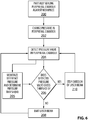
- the differential pressure generator 48 is turned on so as to create the differential pressure zone within the peripheral chamber 44 at 202.
- the controller 66 starts monitoring the readings of the pressure values at 204 inside the peripheral chamber 44 received from the at least one pressure sensor.
Landscapes
- Engineering & Computer Science (AREA)
- Physics & Mathematics (AREA)
- Optics & Photonics (AREA)
- Mechanical Engineering (AREA)
- Plasma & Fusion (AREA)
- Robotics (AREA)
- Laser Beam Processing (AREA)
Description
- The present invention generally relates to the field of manufacturing operations using a laser. More specifically, the invention relates to a laser processing equipment and a method of laser processing a workpiece, using a containment device for an industrial laser head preventing hazardous laser light from escaping the device and allowing the use of the laser head in an open environment.
- Industrial laser equipment is commonly used for different industrial activities such as cutting, welding, cleaning, machining and engraving of many solid materials. Because of the high energy levels emitted by the laser beams of laser heads on such pieces of equipment, it is common to place such laser equipment within a closed room so that it can be isolated from workers, thereby preventing any incident where radiations of the laser beam could reach a worker.
- Not only such dedicated rooms represent a considerable investment, they also require much dedicated space in a manufacturing plant and offer low flexibility when it comes to the size of objects they can accommodate. To alleviate these problems, laser containment devices are now preferably used over laser heads, thereby eliminating the need of a dedicated laser processing room. However, such containment devices need to have flexible flanges in order to accommodate small irregularities in workpieces. However, these flanges, when flexing, may leave a gap with the workpiece so that radiations from the laser beam may escape and potentially endanger a worker in the vicinity of the laser processing equipment.
- There is therefore a need for an improved laser processing equipment and for an improved processing method using such laser processing equipment.
- A laser processing equipment for processing a workpiece is known from
DE2152100A1 (basis for the preamble ofclaims 1 and 11 respectively). The laser processing equipment is provided with a cascade pump with two successive pumped steps for maintaining a regulated atmosphere at a laser beam welding location. The cascade pump comprises two concentric chambers, each with one open end placed close to the surface to be welded, the inner chamber being evacuated by a main vacuum pump, and the outer chamber by a secondary pump. A third chamber for laser beam welding is located above the main vacuum chamber and electrons are injected from it into the main chamber directed onto the surface to be welded. - A laser machine for working a workpiece with a laser beam is disclosed in
DE4331262A1 . The laser itself, or an optical system which focuses the laser beam is movable parallel to the direction of the laser beam. In an operative position of the laser and/or the optical system, the laser beam is surrounded by first shielding elements while scattered light of the laser beam reflected from the workpiece is caught by second shielding elements. A sensor assigned to the movable laser and/or the movable optical system is provided for local temperature measurement in a locally defined region which includes the point of incidence of the laser beam upon the workpiece in the operational position of the laser and/or the optical system. The laser is switched off in dependence on the temperature measured by the sensor when the temperature drops below a preset minimum value. - A method and a device for measuring the size of through opening produced when drilling a workpiece with laser radiation are disclosed in
US5089685A . The arrangement comprises a chamber for a workpiece; a supply channel and a withdrawal channel for supplying a fluid to the chamber and withdrawing the fluid from the chamber; a radiation source; a window provided adjacent to the chamber at its side facing toward the radiation source; and radiation permeable material closing the window. The arrangement further comprises a movable connecting block provided with a workpiece receptacle. After inserting the workpiece, the connecting block abuts against the chamber at its side which is opposite to the window so as to tightly close the chamber. The connecting block has an additional opening. A throughflow quantity meter is arranged in the additional opening for detecting a quantity of fluid flowing through the opening of the workpiece; The arrangement is further provided with means for evaluating output signals of the throughflow quantity meter and controlling and/or switching off of a radiation source. - It is an object of the present invention to provide a laser containment device, a laser processing equipment and a processing method that overcomes or mitigates one or more disadvantages of known laser processing equipment and processing methods, or at least provides a useful alternative.
- The invention provides the advantages of preventing harmful laser beam radiations from escaping and hurting a person in the vicinity of a laser processing equipment.
- In accordance with another embodiment of the present invention there is provided a laser processing equipment for processing a workpiece, as defined in
claim 1. - According to another aspect of the invention, there is provided a laser processing equipment for processing a workpiece, as defined in claim 11.
- Further preferred embodiments of the equipment and the method are defined in claims 2-10 and 12-14 respectively.
- These and other features of the present invention will become more apparent from the following description in which reference is made to the appended drawings wherein:
-
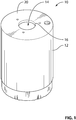
Figure 1 is an isometric view of a laser containment device in accordance with an embodiment of the present invention; -
Figure 2 is a cross-sectional front view of the laser containment device ofFigure 1 connected to a laser head; -
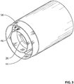
Figure 3 is an isometric view from below of the laser containment device ofFigure 1 ; -
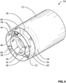
Figure 4 is an isometric view from below of a laser containment device in accordance with another embodiment of the present invention; -
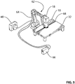
Figure 5 is an isometric view of the laser containment device ofFigure 1 mounted to a laser head which is itself mounted to a manipulator; -
Figure 6 is a flow chart of a method of laser welding using the laser containment device ofFigure 1 in accordance with another embodiment of the present invention. - The present invention relates to a laser containment device for containing a laser beam emitted by a laser head used to process a workpiece, to a laser processing equipment using such a laser containment device and to a method of laser processing. Advantageously, the laser containment device is capable of detecting a change in internal pressure indicative of a break of a seal against the workpiece. By stopping an emission of the laser beam upon this detection, a controller may help in preventing harmful laser beam radiations from escaping the laser containment device.
- The present invention may be used in combination with many type of laser head and laser processing equipment for different industrial processes. Such industrial processes may include cutting, welding, cleaning, machining, engraving, additive manufacturing, etc. In all cases, the common point is that a laser head emitting a laser beam is used in the processing. To ease the understanding, a specific example of the present invention applied to the welding process will be described hereafter. It will be understood however that the same principles may be used for the other processes.
-
Figure 1 is referred to. Thelaser containment device 10 comprises anouter shell 12 enclosing at least partially acontainment chamber 14. Amain port 16 is adapted to receive alaser welding head 18, best shown inFigure 2 now concurrently referred to. Themain port 16 is preferably centered at atop face 20 of theouter shell 12, but could also be placed off-center or even on aside wall 22 of theouter shell 12. - The
laser welding head 18 is secured to theouter shell 12 withattachments 24. Althoughsuch attachments 24 could be permanent, such as a weld or rivets, they are preferably removable, such as screws, a latch or any other known convenient non-permanent mounting means, so that thelaser containment device 10 may be fitted to differentlaser welding heads 18. - A bottom opening 26, provided at a
bottom face 28 of theouter shell 12, is used to allow thelaser beam 30 to reach theworkpiece 32. Thelaser welding head 18 is installed over themain port 16 in theouter shell 12, which is preferably opposite and aligned with the bottom opening 26 so that thelaser welding head 18 may shoot itslaser beam 30 straight through the bottom opening. Alternatively, themain port 16 and the laser welding head could be mounted non-aligned with the bottom opening 26, while still aiming to theworkpiece 32 through the bottom opening 26. Another option may be to use a mirror system inside thecontainment chamber 14 to redirect thelaser beam 30 from thelaser welding head 18 through thebottom opening 26. - The
outer shell 12 may be equipped with avent 34 to vent thecontainment chamber 14 outside theouter shell 12. - The
outer shell 12 may also be equipped with anaccessory port 36 used to accommodate a conventional welding device such as a GMAW or GTAW torch. This welding device may be mounted either to thelaser containment device 10, to thelaser welding head 18 or directly to a manipulator 64 (best shown inFigure 5 ), reaching within thecontainment chamber 14 through anaccessory port 36 and pointing at the bottom opening 26 so as to be operative to weld theworkpiece 32. -
Figure 3 is now concurrently referred to. At least at a workingextremity 40 of thelaser containment device 10, aninner wall 42 extend inside theouter shell 12. It is possible to have thisinner wall 42 extend a whole height of theside wall 22, but this is not really advantageous. Theouter shell 12 and theinner wall 42 define there in-between aperipheral chamber 44. Thisperipheral chamber 44, which is open at thebottom face 28, encircles thebottom opening 26. Theperipheral chamber 44 has apressure port 46 so as to be connected to a differential pressure generator 48 (best shown inFigure 5 , now concurrently referred to). Thedifferential pressure generator 48 is operative to generate a differential pressure within theperipheral chamber 44. Herein, differential pressure is defined as a pressure that is different than an ambient pressure outside theouter shell 12 oflaser containment device 10, which ambient pressure usually corresponds to an atmospheric pressure. Hence, the differential pressure may be lower or higher than the ambient pressure. The difference between the differential pressure and the ambient pressure must constantly be larger than a threshold so that if a leak occurs, it may eventually cross the threshold. Because the present invention works with both a differential pressure that is higher or lower than the ambient pressure, there may be cases where the differential pressure needs to remain below the absolute value of the threshold (in case a vacuum is created in the peripheral chamber) and cases where the differential pressure needs to remain above the absolute value of the threshold (in case a pressurized peripheral chamber is used). Hence, whether the threshold is crossed from above or from below, depending on the type of differential pressure, it triggers something to be true. - Advantageously, the
laser containment device 10 may be used in combination with different types ofdifferential pressure generator 48. For example, if a compressor is used as thedifferential pressure generator 48, then a high pressure condition (higher than the ambient pressure) will be created within theperipheral chamber 44. Conversely, if a vacuum pump is used as thedifferential pressure generator 48, then a low pressure condition (lower than the ambient pressure) is created within theperipheral chamber 44. - An
inner seal 50 and anouter seal 52 are respectively mounted to theinner wall 42 and to theouter shell 12, proximate thebottom face 28. Both inner andouter seals workpiece 32 and prevent laser beam radiation from escaping thelaser containment device 10. Such seals may use bristles, a flexible lip, a deformable open or closed-section seal, or any other type of adequate seal. Both inner andouter seals inner seals 50, 52). Such inner andouter seals workpiece 32. Such variations may be either depressions, such as welding chamfers, or may bulge from theworkpiece 32, such as an existing weld joint for example. - Optionally, the
peripheral chamber 44 may be split in at least twosub-chambers 54 using asmany dividers 56. This option is shown inFigure 4 , now concurrently referred to, where threesub-chambers 54, delimited by threedividers 56 are depicted. Each one of thedividers 56 is equipped with its ownthird seal 60 mounted to thedividers 56 proximate thebottom face 28 so as to contact theworkpiece 32. - In order to read the differential pressure created within the
peripheral chamber 44 by thedifferential pressure generator 48, apressure sensor 58 is connected to theperipheral chamber 44. Thispressure sensor 58 may be mounted within theperipheral chamber 44 to best read the differential pressure. For redundancy and increased accuracy, more than onepressure sensors 58 may be used to read the differential pressure inside theperipheral chamber 44. - In case the
peripheral chamber 44 is divided in two or more sub-chambers 54, each one of the sub-chambers 54 is equipped with itsown pressure sensor 58. Advantageously, this allows more accurate measurements of the differential pressure inside theperipheral chamber 44 since the volume of air in asingle sub-chamber 54 is smaller, thereby making a loss of seal with theworkpiece 32 more influential on the differential pressure inside the affectedsub-chamber 54. Again, for redundancy or averaging, each sub-chamber 54 may be equipped with more than onepressure sensors 58. -
Figure 5 depicts alaser welding equipment 62 used to weld theworkpiece 32. Thelaser welding equipment 62 comprises themanipulator 64 to which extremity is connected thelaser welding head 18 and thelaser containment device 10, acontroller 66 and thedifferential pressure generator 48. Thecontroller 66 may be provided with, or separately from thelaser containment device 10. Themanipulator 64, most usually a computer-controlled robotic arm, is capable of manipulating thelaser welding head 18 and thelaser containment device 10 to precisely follow a joint 68 to be welded in theworkpiece 32. -
Figure 6 is now concurrently referred to. In preparation for welding, thelaser welding head 18 is mounted to the extremity of themanipulator 64 while thelaser containment device 10 is mounted to thelaser welding head 18. The controller positions themanipulator 64 so that thewelding head 18 is in place to start welding. At 200, the inner andouter seals laser containment device 10 come into contact with theworkpiece 32 so as to at least partially seal theperipheral chamber 44 against theworkpiece 32. Once ready, thedifferential pressure generator 48 is turned on so as to create the differential pressure zone within theperipheral chamber 44 at 202. Simultaneously, thecontroller 66 starts monitoring the readings of the pressure values at 204 inside theperipheral chamber 44 received from the at least one pressure sensor. Although only onepressure sensor 58 could be used inside theperipheral chamber 44, for the sake of example, it will be presumed that more than one pressure sensors are used. Once the pressure inside theperipheral chamber 44 is stabilized, and that the pressure values are indicative of an adequate seal between theseals workpiece 32, then an initial reference pressure value is memorized by thecontroller 66 and an adequate pressure threshold is determined at 205. At 206, thecontroller 66 compares the detected pressure values to the predetermined pressure threshold. If the pressure values do not cross the predetermined pressure threshold, that is if the pressure values are within an acceptable range from the initial pressure value, indicative of an adequate seal, then the controller sends a signal to thelaser welding head 18 to emit thelaser beam 30 towards theworkpiece 32 and start welding at 208. As themanipulator 64 follows the joint 68 to be welded, thepressure sensors 58 continuously read the differential pressure inside theperipheral chamber 44 and send these readings to thecontroller 66 which continuously compares these pressure values to the predetermined pressure threshold. Optionally, thecontroller 66 could also mathematically manipulate these pressure values before comparing them to the predetermined pressure threshold. For example, thecontroller 66 could compare two pressure values from twodifferent pressure sensors 58 located in thesame sub-chamber 54 and average them to determine the pressure value to be compared with the predetermined pressure threshold. As long as the pressure values do not cross the predetermined pressure threshold, thecontroller 66 instruct the laser welding head to continue welding. In the case where a loss of seal would occur between the workpiece 32 and either one of the inner andouter seals controller 66 immediately turns off the emission of thelaser beam 30 at 210 until the pressure readings return to being lower than the predetermined pressure threshold. - The value of the predetermined pressure threshold is experimentally determined by correlating a gap between the combination of
inner seal 50 andouter seal 52 and theworkpiece 32 with the intensity of laser radiation emission in the surroundings of thelaser containment device 10. These emission of laser radiation are further dependent on the value of the pressure differential that is generated within the peripheral chamber and on the dimensions of peripheral chamber. Such emissions of laser radiation must be below a maximum permissible exposure according to a recognized safety standard such as IEC60825, a standard on the safety of laser products. - The present invention has been described with regard to preferred embodiments. The description as much as the drawings were intended to help the understanding of the invention, rather than to limit its scope. It will be apparent to one skilled in the art that various modifications may be made to the invention without departing from the scope of the invention as described herein, and such modifications are intended to be covered by the present description. The invention is defined by the claims that follow.
Claims (14)
- A laser processing equipment (62) for processing a workpiece (32), the laser processing equipment comprising:a laser head (18) operative to emit a laser beam;a laser containment device (10) connected to said laser head, said laser containment device having:an outer shell (12) at least partially enclosing a containment chamber (14), said outer shell (12) being connected to said laser head (18) so at to accommodate the laser beam inside said outer shell (12);a laser beam output port (26) in a bottom face (28) of said outer shell (12), said laser beam output port (26) being operative to let the laser beam through so as to reach the workpiece (32);an inner wall (42);a peripheral chamber (44) defined in-between said outer shell (12) and said inner wall (42), said peripheral chamber (44) being open at said bottom face (28), said peripheral chamber (44) encircling said laser beam output port (26);characterized in that the laser containment device further comprisesan inner seal (50) mounted to said inner wall (42) proximate said bottom face (28), said inner seal (50) being operative to contact the workpiece (32);an outer seal (52) mounted to said outer shell (12) proximate said bottom face (28), said outer seal (52) being operative to contact the workpiece (32);and in that the laser processing equipment further comprises:a pressure sensor (58) adapted to detect a differential pressure within said peripheral chamber (44) and to generate a signal indicative of a value of said differential pressure;a differential pressure generator (48) connected to said peripheral chamber (44), said differential pressure generator (48) being operative to generate said differential pressure at a value different from that of an ambient pressure outside said peripheral chamber (44); anda controller (66) operative to selectively operate said laser head (18) based on said signal received from said pressure sensor (58) wherein said controller (66) is operative to shut down an emission of the laser beam from said laser head (18) upon receiving said signal from said pressure sensor (58) and determining that said differential pressure within said peripheral chamber (44) has crossed a predetermined threshold.
- The laser processing equipment of claim 1 further comprising attachments (24) on said outer shell (12) for attaching said containment device (10) to the laser head (18).
- The laser processing equipment of any one of the preceding claims, further comprising a laser beam input port (16) for permitting the laser beam to enter said containment chamber (14), wherein said laser beam input port (16) is distal from the bottom face (28) of said outer shell (12).
- The laser processing equipment of claim 3, wherein the laser beam input port (16) is located opposite said laser beam output port (26).
- The laser processing equipment of any one of the preceding claims, further comprising an accessory port (36) in said outer shell (12), said accessory port (36) being operative to accommodate a second processing device.
- The laser processing equipment of any one of the preceding claims, wherein said pressure sensor (58) is placed inside said peripheral chamber (44).
- The laser processing equipment of any one of the preceding claims, wherein said peripheral chamber (44) is split in at least two sub-chambers (54) by at least two dividers (56), each one of said at least two dividers (56) being equipped with a third seal (60) proximate said bottom face (28), each one of said at least two sub-chambers (54) being equipped with at least one of said pressure sensor (58).
- The laser processing equipment of any one of the preceding claims, further comprising a manipulator (64), said laser head (18) being connected to a working extremity of said manipulator (64), wherein said manipulator (64) is preferably a computer-controlled robotic arm.
- The laser processing equipment of any one of the preceding claims, wherein said laser head (18) is a laser welding head and said laser processing equipment (62) is a laser welding equipment.
- The laser processing equipment of claim 9 in combination with claim 4, further comprising a second welding head protruding at least partially inside said containment chamber (14) through said accessory port (36) in said outer shell (12) so as to be operative to weld the workpiece (32) through said laser beam output port (26).
- A method of laser processing a workpiece (32) using a laser containment device (10) operatively connected to a laser head (18) operative to emit a laser beam (30), the method comprising:encircling with a peripheral chamber (44) an opening (26) in a first chamber (14) of said containment device (10), said opening (26) being operative to accommodate said laser beam (30), said peripheral chamber (44) being located at a working end of said laser containment device (10);and being characterised by the following steps :sealing said peripheral chamber (44) of said laser containment device (10) from said first chamber (14), said sealing occurring against the workpiece (32);creating a differential pressure zone in said peripheral chamber (44) using a differential pressure generator (48) connected to said peripheral chamber (44), said differential pressure generator (48) being operative to create a pressure value within said peripheral chamber (44) that is different from an ambient pressure outside said peripheral chamber (44);detecting a pressure value within said peripheral chamber (44) using a pressure sensor (58), said pressure sensor (58) being in communication with said peripheral chamber (44);generating a signal indicative of said pressure value within said peripheral chamber using said pressure sensor (58), said pressure sensor (58) being operative to send said signal to a controller (66);comparing said detected pressure value with a predetermined pressure threshold using said controller (66); andusing said controller (66) for deciding whether or not to emit the laser beam (30) towards the workpiece (32) based on a result of said comparison, said controller (66) being operative to send a laser beam operation signal to said laser head (18) when said detected pressure value is within said pressure threshold and to stop sending said laser beam operation signal to said laser head (18) when said detected pressure value crosses said pressure threshold.
- The method of claim 11 further comprising guiding said laser head (18) using a computer-controlled robotic arm (64).
- The method of any one of claims 11 to 12, wherein said laser head (18) is a laser welding head, said processing is welding and said laser processing method is a laser welding method.
- The method of any one of claims 11 to 13, comprising determining said pressure threshold using said controller (66), said pressure threshold being based an initial pressure value detected by said pressure sensor (58), said initial pressure value being indicative of an adequate seal.
Priority Applications (1)
| Application Number | Priority Date | Filing Date | Title |
|---|---|---|---|
| PL17193848T PL3315248T3 (en) | 2016-09-28 | 2017-09-28 | Laser processing equipment with a containement device and a laser head and corresponding method of laser processing a workpiece |
Applications Claiming Priority (1)
| Application Number | Priority Date | Filing Date | Title |
|---|---|---|---|
| US15/278,720 US10471539B2 (en) | 2016-09-28 | 2016-09-28 | Containment device for a laser head and associated manufacturing method |
Publications (2)
| Publication Number | Publication Date |
|---|---|
| EP3315248A1 EP3315248A1 (en) | 2018-05-02 |
| EP3315248B1 true EP3315248B1 (en) | 2019-09-25 |
Family
ID=57357058
Family Applications (1)
| Application Number | Title | Priority Date | Filing Date |
|---|---|---|---|
| EP17193848.3A Active EP3315248B1 (en) | 2016-09-28 | 2017-09-28 | Laser processing equipment with a containement device and a laser head and corresponding method of laser processing a workpiece |
Country Status (5)
| Country | Link |
|---|---|
| US (1) | US10471539B2 (en) |
| EP (1) | EP3315248B1 (en) |
| CN (1) | CN107866633B (en) |
| CA (1) | CA2943319C (en) |
| PL (1) | PL3315248T3 (en) |
Families Citing this family (16)
| Publication number | Priority date | Publication date | Assignee | Title |
|---|---|---|---|---|
| JPWO2019082312A1 (en) * | 2017-10-25 | 2020-11-26 | 株式会社ニコン | Processing equipment and manufacturing method of moving body |
| US10713919B2 (en) * | 2018-11-15 | 2020-07-14 | Raytheon Company | Laser damage detection mechanisms for safety interlock and fault detection |
| DE102018132632A1 (en) * | 2018-12-18 | 2020-06-18 | Bombardier Transportation Gmbh | VEHICLE |
| CN111738246A (en) * | 2019-03-25 | 2020-10-02 | 北京小米移动软件有限公司 | Electronic device and control method thereof, and machine-readable storage medium |
| EP3946802B1 (en) * | 2019-04-02 | 2025-09-10 | EuWe Eugen Wexler Holding GmbH & Co. KG | Apparatus for processing of a workpiece by means of at least one energy beam, shielding device for such an apparatus, and method of processing of a workpiece by means of at least one energy beam |
| JP6884184B2 (en) * | 2019-09-25 | 2021-06-09 | 株式会社牧野フライス製作所 | Water jet laser machine |
| CN112207440A (en) * | 2020-10-29 | 2021-01-12 | 柴爱萍 | Novel laser head and welding device |
| DE102021104512A1 (en) | 2021-02-25 | 2022-08-25 | Fachhochschule Aachen | Welding process using a mobile vacuum chamber |
| CN116604181A (en) * | 2022-02-09 | 2023-08-18 | 本田技研工业株式会社 | Method for manufacturing joint member and joint member |
| CN114686678B (en) * | 2022-04-24 | 2024-01-05 | 江苏大学 | Laser impact combined strengthening device and method for gear |
| KR102705415B1 (en) * | 2022-05-20 | 2024-09-11 | 한국생산기술연구원 | Low pressure forming apparatus for laser welding, laser welding device and laser welding method including the same |
| CN115213542B (en) * | 2022-09-08 | 2023-01-20 | 中国核动力研究设计院 | Control method of vacuum diffusion welding equipment, vacuum diffusion welding equipment and storage medium |
| CN117283128B (en) * | 2022-11-17 | 2026-01-30 | 洛阳船舶材料研究所(中国船舶集团有限公司第七二五研究所) | A local vacuum laser welding device and welding method |
| FR3155730A1 (en) * | 2023-11-29 | 2025-05-30 | Arcspace | Welding device including an anti-contamination hood |
| CN117900705A (en) * | 2024-02-28 | 2024-04-19 | 奥特(南京)科技有限公司 | Automatic change preheating device before welding |
| CN118989840B (en) * | 2024-10-25 | 2025-03-28 | 江苏东冶轧辊有限公司 | A new type of roller welding tool and its welding process |
Family Cites Families (22)
| Publication number | Priority date | Publication date | Assignee | Title |
|---|---|---|---|---|
| DE2152100A1 (en) | 1971-10-19 | 1973-04-26 | Vickers Ltd | Cascade pump - for electron beam welding appts |
| JPS57156888A (en) | 1981-03-25 | 1982-09-28 | Toshiba Corp | Shielding device for laser welding |
| DE3942299C2 (en) | 1989-12-21 | 1995-04-27 | Bosch Gmbh Robert | Method and apparatus for continuously measuring the size of through holes |
| FR2667527B1 (en) * | 1990-10-08 | 1993-01-22 | Fbfc | DRILLING AND / OR LASER CLOSURE EQUIPMENT OF THE POCKET HOLE OF A FUEL PENCIL. |
| DE4331262C2 (en) | 1993-09-15 | 1996-05-15 | Wissner Rolf | Laser machine for machining a workpiece and method for controlling a laser machine |
| JP3385361B2 (en) | 2000-05-09 | 2003-03-10 | 北海道大学長 | Laser welding method and laser welding apparatus |
| US20030199974A1 (en) * | 2002-04-18 | 2003-10-23 | Coalescent Surgical, Inc. | Annuloplasty apparatus and methods |
| DE20221984U1 (en) | 2002-11-28 | 2010-02-11 | Baeger, Holm, Dr.-Ing. | Laser arrangement for processing, in particular inscription of workpiece surfaces |
| US7179062B1 (en) * | 2005-10-21 | 2007-02-20 | Drevitson Kyle C | Integrated shop vacuum and air compressor system |
| US20070199930A1 (en) * | 2006-02-22 | 2007-08-30 | Mecco Partnership, Llc | Laser marking system |
| JP2008143388A (en) * | 2006-12-11 | 2008-06-26 | Fukashi Uragami | Device which can come into close contact with surface of object located in liquid and can move along surface of object |
| CN101264554A (en) * | 2008-04-01 | 2008-09-17 | 沈阳航空工业学院 | A vacuum system for laser processing |
| DE102008019095B3 (en) | 2008-04-11 | 2009-08-13 | Jenoptik Automatisierungstechnik Gmbh | Laser machining system for three-dimensionally expanded workpiece, comprises laser radiation source, laser head, robot over its robotic arm, workpiece receiving device, protection housing connected with suction device, and device support |
| US8207472B2 (en) | 2008-06-18 | 2012-06-26 | Electro Scientific Industries, Inc. | Debris capture and removal for laser micromachining |
| US8053701B2 (en) | 2008-10-28 | 2011-11-08 | The Boeing Company | Inert gas cover system for laser welding |
| KR20110019518A (en) * | 2009-08-20 | 2011-02-28 | 삼성전자주식회사 | Nozzle for substrate adsorption and substrate transfer apparatus having the same |
| DE202009013899U1 (en) | 2009-10-13 | 2010-02-18 | Trumpf Werkzeugmaschinen Gmbh + Co. Kg | Shielding device on a machining head and machining head and processing machine with a shielding device |
| EP2540435A1 (en) | 2011-07-01 | 2013-01-02 | Siemens Vai Metals Technologies SAS | Safety enclosure for laser radiation confinement |
| DE102012106278B4 (en) | 2012-04-13 | 2016-04-14 | Scansonic Mi Gmbh | Laser protection device for detecting laser radiation |
| FR2994116B1 (en) | 2012-08-02 | 2014-08-29 | Commissariat Energie Atomique | IMMERSIBLE LASER HEAD |
| DE102012215147B4 (en) | 2012-08-27 | 2017-04-27 | Trumpf Laser Gmbh | Laser processing head with spring-resistant shielding plates |
| JP6037741B2 (en) | 2012-09-18 | 2016-12-07 | 三菱重工工作機械株式会社 | Mobile vacuum welding equipment |
-
2016
- 2016-09-28 CA CA2943319A patent/CA2943319C/en active Active
- 2016-09-28 US US15/278,720 patent/US10471539B2/en active Active
-
2017
- 2017-09-25 CN CN201710875556.9A patent/CN107866633B/en active Active
- 2017-09-28 EP EP17193848.3A patent/EP3315248B1/en active Active
- 2017-09-28 PL PL17193848T patent/PL3315248T3/en unknown
Non-Patent Citations (1)
| Title |
|---|
| None * |
Also Published As
| Publication number | Publication date |
|---|---|
| CN107866633A (en) | 2018-04-03 |
| US20180085854A1 (en) | 2018-03-29 |
| PL3315248T3 (en) | 2020-06-29 |
| CA2943319C (en) | 2017-08-01 |
| CN107866633B (en) | 2020-04-28 |
| EP3315248A1 (en) | 2018-05-02 |
| US10471539B2 (en) | 2019-11-12 |
| CA2943319A1 (en) | 2016-11-25 |
Similar Documents
| Publication | Publication Date | Title |
|---|---|---|
| US10471539B2 (en) | Containment device for a laser head and associated manufacturing method | |
| KR102099996B1 (en) | Laser processing device having a laser processing head which can be moved relative to a clamping claw | |
| US20170129039A1 (en) | System for Processing a Workpiece | |
| KR102130694B1 (en) | Robotic laser seam stepper | |
| KR102123133B1 (en) | Machine tool and method for machining a workpiece | |
| US6894248B2 (en) | Laser beam machining apparatus | |
| JP2009527363A (en) | Laser marking system | |
| TW201902616A (en) | Photoelectric equipment and related protective devices for inspecting mechanical parts | |
| US12162094B2 (en) | Laser welding enclosure | |
| US20230061659A1 (en) | Handheld laser machining apparatus for machining a workpiece, and funnel for a handheld laser machining apparatus | |
| US6681672B2 (en) | Optimized band saw feed speed system | |
| KR20160125521A (en) | Machine and method for the material processing of workpieces by way of a laser beam | |
| US5075534A (en) | Arc sensor provided with a transparent objective window having a contamination preventing construction | |
| KR20200028206A (en) | System for welding and cutting using laser | |
| KR102797554B1 (en) | Apparatus for underwater laser cutting | |
| EP3637043A1 (en) | Non-contact tool measurement apparatus | |
| KR100517380B1 (en) | Vision sensor equipped with automatic cooling and heating system by measuring temperature sensor | |
| JP7198133B2 (en) | MOISTURE INTRUSION DETECTION SYSTEM AND MOISTURE INTRUSION DETECTION METHOD | |
| US20240075554A1 (en) | Portable device for laser marking | |
| EP3946802B1 (en) | Apparatus for processing of a workpiece by means of at least one energy beam, shielding device for such an apparatus, and method of processing of a workpiece by means of at least one energy beam | |
| US11806812B2 (en) | Laser machining device | |
| KR20210039509A (en) | Welding carriage having auto stop fuction | |
| KR20150078313A (en) | Apparatus for oil mist measuring using laser | |
| CN110695541B (en) | Tool assembly and method for accommodating an optical tool in a parked position | |
| IT202100006938A1 (en) | LASER DEVICE FOR METALWORKING AND EQUIPMENT INCLUDING SUCH DEVICE |
Legal Events
| Date | Code | Title | Description |
|---|---|---|---|
| PUAI | Public reference made under article 153(3) epc to a published international application that has entered the european phase |
Free format text: ORIGINAL CODE: 0009012 |
|
| STAA | Information on the status of an ep patent application or granted ep patent |
Free format text: STATUS: THE APPLICATION HAS BEEN PUBLISHED |
|
| AK | Designated contracting states |
Kind code of ref document: A1 Designated state(s): AL AT BE BG CH CY CZ DE DK EE ES FI FR GB GR HR HU IE IS IT LI LT LU LV MC MK MT NL NO PL PT RO RS SE SI SK SM TR |
|
| AX | Request for extension of the european patent |
Extension state: BA ME |
|
| STAA | Information on the status of an ep patent application or granted ep patent |
Free format text: STATUS: REQUEST FOR EXAMINATION WAS MADE |
|
| 17P | Request for examination filed |
Effective date: 20181106 |
|
| RBV | Designated contracting states (corrected) |
Designated state(s): AL AT BE BG CH CY CZ DE DK EE ES FI FR GB GR HR HU IE IS IT LI LT LU LV MC MK MT NL NO PL PT RO RS SE SI SK SM TR |
|
| GRAP | Despatch of communication of intention to grant a patent |
Free format text: ORIGINAL CODE: EPIDOSNIGR1 |
|
| STAA | Information on the status of an ep patent application or granted ep patent |
Free format text: STATUS: GRANT OF PATENT IS INTENDED |
|
| INTG | Intention to grant announced |
Effective date: 20190426 |
|
| GRAS | Grant fee paid |
Free format text: ORIGINAL CODE: EPIDOSNIGR3 |
|
| GRAA | (expected) grant |
Free format text: ORIGINAL CODE: 0009210 |
|
| STAA | Information on the status of an ep patent application or granted ep patent |
Free format text: STATUS: THE PATENT HAS BEEN GRANTED |
|
| AK | Designated contracting states |
Kind code of ref document: B1 Designated state(s): AL AT BE BG CH CY CZ DE DK EE ES FI FR GB GR HR HU IE IS IT LI LT LU LV MC MK MT NL NO PL PT RO RS SE SI SK SM TR |
|
| REG | Reference to a national code |
Ref country code: GB Ref legal event code: FG4D |
|
| REG | Reference to a national code |
Ref country code: CH Ref legal event code: EP |
|
| REG | Reference to a national code |
Ref country code: AT Ref legal event code: REF Ref document number: 1183334 Country of ref document: AT Kind code of ref document: T Effective date: 20191015 |
|
| REG | Reference to a national code |
Ref country code: IE Ref legal event code: FG4D |
|
| REG | Reference to a national code |
Ref country code: DE Ref legal event code: R096 Ref document number: 602017007281 Country of ref document: DE |
|
| REG | Reference to a national code |
Ref country code: CH Ref legal event code: NV Representative=s name: MICHELI AND CIE SA, CH |
|
| REG | Reference to a national code |
Ref country code: NL Ref legal event code: MP Effective date: 20190925 |
|
| PG25 | Lapsed in a contracting state [announced via postgrant information from national office to epo] |
Ref country code: BG Free format text: LAPSE BECAUSE OF FAILURE TO SUBMIT A TRANSLATION OF THE DESCRIPTION OR TO PAY THE FEE WITHIN THE PRESCRIBED TIME-LIMIT Effective date: 20191225 Ref country code: LT Free format text: LAPSE BECAUSE OF FAILURE TO SUBMIT A TRANSLATION OF THE DESCRIPTION OR TO PAY THE FEE WITHIN THE PRESCRIBED TIME-LIMIT Effective date: 20190925 Ref country code: HR Free format text: LAPSE BECAUSE OF FAILURE TO SUBMIT A TRANSLATION OF THE DESCRIPTION OR TO PAY THE FEE WITHIN THE PRESCRIBED TIME-LIMIT Effective date: 20190925 Ref country code: SE Free format text: LAPSE BECAUSE OF FAILURE TO SUBMIT A TRANSLATION OF THE DESCRIPTION OR TO PAY THE FEE WITHIN THE PRESCRIBED TIME-LIMIT Effective date: 20190925 Ref country code: NO Free format text: LAPSE BECAUSE OF FAILURE TO SUBMIT A TRANSLATION OF THE DESCRIPTION OR TO PAY THE FEE WITHIN THE PRESCRIBED TIME-LIMIT Effective date: 20191225 Ref country code: FI Free format text: LAPSE BECAUSE OF FAILURE TO SUBMIT A TRANSLATION OF THE DESCRIPTION OR TO PAY THE FEE WITHIN THE PRESCRIBED TIME-LIMIT Effective date: 20190925 |
|
| REG | Reference to a national code |
Ref country code: LT Ref legal event code: MG4D |
|
| PG25 | Lapsed in a contracting state [announced via postgrant information from national office to epo] |
Ref country code: RS Free format text: LAPSE BECAUSE OF FAILURE TO SUBMIT A TRANSLATION OF THE DESCRIPTION OR TO PAY THE FEE WITHIN THE PRESCRIBED TIME-LIMIT Effective date: 20190925 Ref country code: GR Free format text: LAPSE BECAUSE OF FAILURE TO SUBMIT A TRANSLATION OF THE DESCRIPTION OR TO PAY THE FEE WITHIN THE PRESCRIBED TIME-LIMIT Effective date: 20191226 Ref country code: LV Free format text: LAPSE BECAUSE OF FAILURE TO SUBMIT A TRANSLATION OF THE DESCRIPTION OR TO PAY THE FEE WITHIN THE PRESCRIBED TIME-LIMIT Effective date: 20190925 |
|
| REG | Reference to a national code |
Ref country code: AT Ref legal event code: MK05 Ref document number: 1183334 Country of ref document: AT Kind code of ref document: T Effective date: 20190925 |
|
| PG25 | Lapsed in a contracting state [announced via postgrant information from national office to epo] |
Ref country code: RO Free format text: LAPSE BECAUSE OF FAILURE TO SUBMIT A TRANSLATION OF THE DESCRIPTION OR TO PAY THE FEE WITHIN THE PRESCRIBED TIME-LIMIT Effective date: 20190925 Ref country code: IT Free format text: LAPSE BECAUSE OF FAILURE TO SUBMIT A TRANSLATION OF THE DESCRIPTION OR TO PAY THE FEE WITHIN THE PRESCRIBED TIME-LIMIT Effective date: 20190925 Ref country code: AT Free format text: LAPSE BECAUSE OF FAILURE TO SUBMIT A TRANSLATION OF THE DESCRIPTION OR TO PAY THE FEE WITHIN THE PRESCRIBED TIME-LIMIT Effective date: 20190925 Ref country code: EE Free format text: LAPSE BECAUSE OF FAILURE TO SUBMIT A TRANSLATION OF THE DESCRIPTION OR TO PAY THE FEE WITHIN THE PRESCRIBED TIME-LIMIT Effective date: 20190925 Ref country code: ES Free format text: LAPSE BECAUSE OF FAILURE TO SUBMIT A TRANSLATION OF THE DESCRIPTION OR TO PAY THE FEE WITHIN THE PRESCRIBED TIME-LIMIT Effective date: 20190925 Ref country code: AL Free format text: LAPSE BECAUSE OF FAILURE TO SUBMIT A TRANSLATION OF THE DESCRIPTION OR TO PAY THE FEE WITHIN THE PRESCRIBED TIME-LIMIT Effective date: 20190925 Ref country code: NL Free format text: LAPSE BECAUSE OF FAILURE TO SUBMIT A TRANSLATION OF THE DESCRIPTION OR TO PAY THE FEE WITHIN THE PRESCRIBED TIME-LIMIT Effective date: 20190925 Ref country code: PT Free format text: LAPSE BECAUSE OF FAILURE TO SUBMIT A TRANSLATION OF THE DESCRIPTION OR TO PAY THE FEE WITHIN THE PRESCRIBED TIME-LIMIT Effective date: 20200127 |
|
| PG25 | Lapsed in a contracting state [announced via postgrant information from national office to epo] |
Ref country code: CZ Free format text: LAPSE BECAUSE OF FAILURE TO SUBMIT A TRANSLATION OF THE DESCRIPTION OR TO PAY THE FEE WITHIN THE PRESCRIBED TIME-LIMIT Effective date: 20190925 Ref country code: IS Free format text: LAPSE BECAUSE OF FAILURE TO SUBMIT A TRANSLATION OF THE DESCRIPTION OR TO PAY THE FEE WITHIN THE PRESCRIBED TIME-LIMIT Effective date: 20200224 Ref country code: SK Free format text: LAPSE BECAUSE OF FAILURE TO SUBMIT A TRANSLATION OF THE DESCRIPTION OR TO PAY THE FEE WITHIN THE PRESCRIBED TIME-LIMIT Effective date: 20190925 Ref country code: SM Free format text: LAPSE BECAUSE OF FAILURE TO SUBMIT A TRANSLATION OF THE DESCRIPTION OR TO PAY THE FEE WITHIN THE PRESCRIBED TIME-LIMIT Effective date: 20190925 |
|
| REG | Reference to a national code |
Ref country code: DE Ref legal event code: R097 Ref document number: 602017007281 Country of ref document: DE |
|
| PG2D | Information on lapse in contracting state deleted |
Ref country code: IS |
|
| PG25 | Lapsed in a contracting state [announced via postgrant information from national office to epo] |
Ref country code: DK Free format text: LAPSE BECAUSE OF FAILURE TO SUBMIT A TRANSLATION OF THE DESCRIPTION OR TO PAY THE FEE WITHIN THE PRESCRIBED TIME-LIMIT Effective date: 20190925 Ref country code: LU Free format text: LAPSE BECAUSE OF NON-PAYMENT OF DUE FEES Effective date: 20190928 Ref country code: IE Free format text: LAPSE BECAUSE OF NON-PAYMENT OF DUE FEES Effective date: 20190928 Ref country code: IS Free format text: LAPSE BECAUSE OF FAILURE TO SUBMIT A TRANSLATION OF THE DESCRIPTION OR TO PAY THE FEE WITHIN THE PRESCRIBED TIME-LIMIT Effective date: 20200126 |
|
| PLBE | No opposition filed within time limit |
Free format text: ORIGINAL CODE: 0009261 |
|
| STAA | Information on the status of an ep patent application or granted ep patent |
Free format text: STATUS: NO OPPOSITION FILED WITHIN TIME LIMIT |
|
| REG | Reference to a national code |
Ref country code: BE Ref legal event code: MM Effective date: 20190930 |
|
| PG25 | Lapsed in a contracting state [announced via postgrant information from national office to epo] |
Ref country code: MC Free format text: LAPSE BECAUSE OF FAILURE TO SUBMIT A TRANSLATION OF THE DESCRIPTION OR TO PAY THE FEE WITHIN THE PRESCRIBED TIME-LIMIT Effective date: 20190925 Ref country code: BE Free format text: LAPSE BECAUSE OF NON-PAYMENT OF DUE FEES Effective date: 20190930 |
|
| 26N | No opposition filed |
Effective date: 20200626 |
|
| PG25 | Lapsed in a contracting state [announced via postgrant information from national office to epo] |
Ref country code: SI Free format text: LAPSE BECAUSE OF FAILURE TO SUBMIT A TRANSLATION OF THE DESCRIPTION OR TO PAY THE FEE WITHIN THE PRESCRIBED TIME-LIMIT Effective date: 20190925 |
|
| PG25 | Lapsed in a contracting state [announced via postgrant information from national office to epo] |
Ref country code: CY Free format text: LAPSE BECAUSE OF FAILURE TO SUBMIT A TRANSLATION OF THE DESCRIPTION OR TO PAY THE FEE WITHIN THE PRESCRIBED TIME-LIMIT Effective date: 20190925 |
|
| PG25 | Lapsed in a contracting state [announced via postgrant information from national office to epo] |
Ref country code: HU Free format text: LAPSE BECAUSE OF FAILURE TO SUBMIT A TRANSLATION OF THE DESCRIPTION OR TO PAY THE FEE WITHIN THE PRESCRIBED TIME-LIMIT; INVALID AB INITIO Effective date: 20170928 Ref country code: MT Free format text: LAPSE BECAUSE OF FAILURE TO SUBMIT A TRANSLATION OF THE DESCRIPTION OR TO PAY THE FEE WITHIN THE PRESCRIBED TIME-LIMIT Effective date: 20190925 |
|
| PG25 | Lapsed in a contracting state [announced via postgrant information from national office to epo] |
Ref country code: TR Free format text: LAPSE BECAUSE OF FAILURE TO SUBMIT A TRANSLATION OF THE DESCRIPTION OR TO PAY THE FEE WITHIN THE PRESCRIBED TIME-LIMIT Effective date: 20190925 |
|
| PG25 | Lapsed in a contracting state [announced via postgrant information from national office to epo] |
Ref country code: MK Free format text: LAPSE BECAUSE OF FAILURE TO SUBMIT A TRANSLATION OF THE DESCRIPTION OR TO PAY THE FEE WITHIN THE PRESCRIBED TIME-LIMIT Effective date: 20190925 |
|
| P01 | Opt-out of the competence of the unified patent court (upc) registered |
Effective date: 20231025 |
|
| REG | Reference to a national code |
Ref country code: CH Ref legal event code: U11 Free format text: ST27 STATUS EVENT CODE: U-0-0-U10-U11 (AS PROVIDED BY THE NATIONAL OFFICE) Effective date: 20251001 |
|
| PGFP | Annual fee paid to national office [announced via postgrant information from national office to epo] |
Ref country code: DE Payment date: 20250919 Year of fee payment: 9 |
|
| PGFP | Annual fee paid to national office [announced via postgrant information from national office to epo] |
Ref country code: PL Payment date: 20250923 Year of fee payment: 9 |
|
| PGFP | Annual fee paid to national office [announced via postgrant information from national office to epo] |
Ref country code: GB Payment date: 20250919 Year of fee payment: 9 |
|
| PGFP | Annual fee paid to national office [announced via postgrant information from national office to epo] |
Ref country code: FR Payment date: 20250922 Year of fee payment: 9 |
|
| PGFP | Annual fee paid to national office [announced via postgrant information from national office to epo] |
Ref country code: CH Payment date: 20251001 Year of fee payment: 9 |