EP3315077A1 - Ultrasonic endoscope - Google Patents
Ultrasonic endoscope Download PDFInfo
- Publication number
- EP3315077A1 EP3315077A1 EP16814021.8A EP16814021A EP3315077A1 EP 3315077 A1 EP3315077 A1 EP 3315077A1 EP 16814021 A EP16814021 A EP 16814021A EP 3315077 A1 EP3315077 A1 EP 3315077A1
- Authority
- EP
- European Patent Office
- Prior art keywords
- ultrasound
- functional unit
- endoscope
- longitudinal axis
- insertion portion
- Prior art date
- Legal status (The legal status is an assumption and is not a legal conclusion. Google has not performed a legal analysis and makes no representation as to the accuracy of the status listed.)
- Withdrawn
Links
Images




Classifications
-
- A—HUMAN NECESSITIES
- A61—MEDICAL OR VETERINARY SCIENCE; HYGIENE
- A61B—DIAGNOSIS; SURGERY; IDENTIFICATION
- A61B8/00—Diagnosis using ultrasonic, sonic or infrasonic waves
- A61B8/12—Diagnosis using ultrasonic, sonic or infrasonic waves in body cavities or body tracts, e.g. by using catheters
-
- A—HUMAN NECESSITIES
- A61—MEDICAL OR VETERINARY SCIENCE; HYGIENE
- A61B—DIAGNOSIS; SURGERY; IDENTIFICATION
- A61B1/00—Instruments for performing medical examinations of the interior of cavities or tubes of the body by visual or photographical inspection, e.g. endoscopes; Illuminating arrangements therefor
- A61B1/00064—Constructional details of the endoscope body
- A61B1/00071—Insertion part of the endoscope body
- A61B1/0008—Insertion part of the endoscope body characterised by distal tip features
- A61B1/00096—Optical elements
-
- A—HUMAN NECESSITIES
- A61—MEDICAL OR VETERINARY SCIENCE; HYGIENE
- A61B—DIAGNOSIS; SURGERY; IDENTIFICATION
- A61B8/00—Diagnosis using ultrasonic, sonic or infrasonic waves
- A61B8/44—Constructional features of the ultrasonic, sonic or infrasonic diagnostic device
- A61B8/4483—Constructional features of the ultrasonic, sonic or infrasonic diagnostic device characterised by features of the ultrasound transducer
-
- A—HUMAN NECESSITIES
- A61—MEDICAL OR VETERINARY SCIENCE; HYGIENE
- A61B—DIAGNOSIS; SURGERY; IDENTIFICATION
- A61B8/00—Diagnosis using ultrasonic, sonic or infrasonic waves
- A61B8/52—Devices using data or image processing specially adapted for diagnosis using ultrasonic, sonic or infrasonic waves
- A61B8/5207—Devices using data or image processing specially adapted for diagnosis using ultrasonic, sonic or infrasonic waves involving processing of raw data to produce diagnostic data, e.g. for generating an image
-
- A—HUMAN NECESSITIES
- A61—MEDICAL OR VETERINARY SCIENCE; HYGIENE
- A61B—DIAGNOSIS; SURGERY; IDENTIFICATION
- A61B8/00—Diagnosis using ultrasonic, sonic or infrasonic waves
- A61B8/52—Devices using data or image processing specially adapted for diagnosis using ultrasonic, sonic or infrasonic waves
- A61B8/5215—Devices using data or image processing specially adapted for diagnosis using ultrasonic, sonic or infrasonic waves involving processing of medical diagnostic data
- A61B8/5238—Devices using data or image processing specially adapted for diagnosis using ultrasonic, sonic or infrasonic waves involving processing of medical diagnostic data for combining image data of patient, e.g. merging several images from different acquisition modes into one image
- A61B8/5261—Devices using data or image processing specially adapted for diagnosis using ultrasonic, sonic or infrasonic waves involving processing of medical diagnostic data for combining image data of patient, e.g. merging several images from different acquisition modes into one image combining images from different diagnostic modalities, e.g. ultrasound and X-ray
-
- A—HUMAN NECESSITIES
- A61—MEDICAL OR VETERINARY SCIENCE; HYGIENE
- A61B—DIAGNOSIS; SURGERY; IDENTIFICATION
- A61B1/00—Instruments for performing medical examinations of the interior of cavities or tubes of the body by visual or photographical inspection, e.g. endoscopes; Illuminating arrangements therefor
- A61B1/00064—Constructional details of the endoscope body
- A61B1/00071—Insertion part of the endoscope body
- A61B1/0008—Insertion part of the endoscope body characterised by distal tip features
- A61B1/00082—Balloons
-
- A—HUMAN NECESSITIES
- A61—MEDICAL OR VETERINARY SCIENCE; HYGIENE
- A61B—DIAGNOSIS; SURGERY; IDENTIFICATION
- A61B1/00—Instruments for performing medical examinations of the interior of cavities or tubes of the body by visual or photographical inspection, e.g. endoscopes; Illuminating arrangements therefor
- A61B1/00163—Optical arrangements
- A61B1/00174—Optical arrangements characterised by the viewing angles
-
- A—HUMAN NECESSITIES
- A61—MEDICAL OR VETERINARY SCIENCE; HYGIENE
- A61B—DIAGNOSIS; SURGERY; IDENTIFICATION
- A61B8/00—Diagnosis using ultrasonic, sonic or infrasonic waves
- A61B8/44—Constructional features of the ultrasonic, sonic or infrasonic diagnostic device
- A61B8/4477—Constructional features of the ultrasonic, sonic or infrasonic diagnostic device using several separate ultrasound transducers or probes
-
- A—HUMAN NECESSITIES
- A61—MEDICAL OR VETERINARY SCIENCE; HYGIENE
- A61B—DIAGNOSIS; SURGERY; IDENTIFICATION
- A61B8/00—Diagnosis using ultrasonic, sonic or infrasonic waves
- A61B8/44—Constructional features of the ultrasonic, sonic or infrasonic diagnostic device
- A61B8/4483—Constructional features of the ultrasonic, sonic or infrasonic diagnostic device characterised by features of the ultrasound transducer
- A61B8/4488—Constructional features of the ultrasonic, sonic or infrasonic diagnostic device characterised by features of the ultrasound transducer the transducer being a phased array
Definitions
- the present invention relates to an ultrasound endoscope including an ultrasound transducer that emits ultrasound waves onto an observation target, receives an ultrasound echo reflected by the observation target, converts the ultrasound echo into an echo signal, and outputs the echo signal.
- an ultrasound observation apparatus can acquire information related to the property of the observation target, by performing predetermined signal processing on an ultrasound echo received from an ultrasound transducer that transmits and receives ultrasound waves.
- the ultrasound transducer includes a plurality of piezoelectric elements that converts an electrical pulse signal into an ultrasound pulse (acoustic pulse), emits the ultrasound pulse onto the observation target, converts the ultrasound echo reflected by the observation target, into an electrical echo signal, and outputs the electrical echo signal. For example, by arranging a plurality of piezoelectric elements along a predetermined direction, and electrically switching an element involved in the transmission and reception, or delaying the transmission and reception of each element, an ultrasound echo is acquired from the observation target.
- a convex-type ultrasound transducer includes a plurality of piezoelectric elements arrayed along a curved surface, and each element emits an ultrasound beam in a radial direction of the curved surface (e.g., refer to Patent Literature 1).
- Patent Literature 1 discloses a configuration in which a convex-type ultrasound transducer is provided at a distal end of an insertion portion of an ultrasound endoscope.
- Patent Literature 1 JP 2004-254942 A
- the ultrasound endoscope disclosed in Patent Literature 1 has such a problem that, if a curvature radius of the curved surface of the convex-type ultrasound transducer (curved surface passing through distal ends of a plurality of piezoelectric elements) is increased, an extension length of the ultrasound transducer with respect to a longitudinal axis direction of the insertion portion becomes long.
- the present invention has been devised in view of the foregoing, and the object of the present invention is to provide an ultrasound endoscope that can increase a curvature radius of an ultrasound transducer without causing upsizing.
- an ultrasound endoscope includes an insertion portion to be inserted into a subject, and includes: an ultrasound functional unit provided at a distal end of the insertion portion, the ultrasound functional unit including an ultrasound transducer configured to transmit and receive an ultrasound wave on a surface including a longitudinal axis of the insertion portion, the surface being parallel to the longitudinal axis; and an endoscope functional unit connected to the ultrasound functional unit, the endoscope functional unit at least including: a balloon locking portion having a groove shape that can lock a balloon; and an imaging optical system, wherein a first plane passes, in a direction of the longitudinal axis of the insertion portion, through an end portion of the ultrasound transducer near the endoscope functional unit, the first plane being perpendicular to the longitudinal axis of the insertion portion, and the first plane is positioned closer to a proximal end than a second plane passing through an end portion of the endoscope functional unit near the ultrasound functional unit, the end portion of
- the ultrasound functional unit is detachable from the endoscope functional unit.
- the above-described ultrasound endoscope according to the present invention further includes a rotation suppression unit configured to suppress rotation of the ultrasound functional unit around an axis that is parallel to the longitudinal axis, with respect to the endoscope functional unit.
- an ultrasound endoscope includes an insertion portion to be inserted into a subject, and includes: an ultrasound functional unit provided at a distal end of the insertion portion, the ultrasound functional unit including an ultrasound transducer configured to transmit and receive an ultrasound wave on a surface including a longitudinal axis of the insertion portion, and the surface being parallel to the longitudinal axis; an endoscope functional unit that at least includes an imaging optical system; and a balloon locking portion configured to connect the ultrasound functional unit and the endoscope functional unit, the balloon locking portion having a groove shape that can lock a balloon, wherein a first plane passes, in a direction of the longitudinal axis of the insertion portion, through a first end portion of the ultrasound transducer near the endoscope functional unit, the first plane being perpendicular to the longitudinal axis of the insertion portion, and the first plane is positioned closer to a proximal end than a second plane passing through a second end portion of the balloon locking portion near the ultrasound functional unit.
- a first distance in a direction of the longitudinal axis from a distal end of the longitudinal axis of the ultrasound functional unit to the second end portion is smaller than a second distance in the direction of the longitudinal axis between both end portions of the ultrasound functional unit.
- m 1 a distance in a direction of the longitudinal axis from a third end portion on a distal end side of the longitudinal axis of the ultrasound functional unit to the second end portion
- m 2 a distance between the first and third end portions
- m 3 a distance in the direction of the longitudinal axis between the first and third end portions
- m 4 a distance that is a largest distance in a direction perpendicular to the longitudinal axis from the third end portion to an end portion of the ultrasound transducer
- m 4 a curvature radius of a curved surface of the ultrasound transducer is denoted by R, an
- FIG. 1 is a diagram schematically illustrating an endoscope system according to a first embodiment of the present invention.
- An endoscope system 1 is a system for performing ultrasound diagnosis of the inside of a subject such as a human, using an ultrasound endoscope. As illustrated in FIG. 1 , the endoscope system 1 includes an ultrasound endoscope 2, an ultrasound observation apparatus 3, an endoscope observation apparatus 4, a display device 5, and a light source device 6.
- the ultrasound endoscope 2 converts an electrical pulse signal received from the ultrasound observation apparatus 3, into an ultrasound pulse (acoustic pulse), emits the ultrasound pulse onto a subject at its distal end portion, converts an ultrasound echo reflected by the subject, into an electrical echo signal represented by voltage change, and outputs the electrical echo signal.
- the ultrasound endoscope 2 normally includes an imaging optical system and an image sensor, is inserted into a digestive tract (esophagus, stomach, duodenum, large intestine) or a respiratory organ (trachea, bronchus) of the subject, and can perform capturing of the digestive tract or the respiratory organ.
- their adjacent organs pancreas, cholecystis, biliary duct, biliary tract, lymph nodes, mediastinum organ, blood vessels, etc.
- the ultrasound endoscope 2 includes a light guide that guides illumination light to be emitted onto a subject when optical capturing is performed.
- the light guide has a distal end portion and a proximal end portion. The distal end portion reaches a distal end of an insertion portion to be inserted into a subject of the ultrasound endoscope 2.
- the proximal end portion is connected to the light source device 6 that generates illumination light.
- the ultrasound endoscope 2 includes an insertion portion 21, an operating unit 22, a universal cord 23, and a connector 24.
- the insertion portion 21 is a portion to be inserted into the subject.
- the insertion portion 21 includes a rigid distal end portion 211 that is provided on a distal end side, and holds a ultrasound transducer 7, a curve portion 212 capable of curving that is connected to a proximal end side of the distal end portion 211, and a flexible tube portion 213 having flexibility that is connected to a proximal end side of the curve portion 212.
- a light guide for transferring illumination light supplied from the light source device 6, and a plurality of signal cables for transferring various signals are laid, and a processing tool insertion path for inserting a processing tool is formed, of which specific illustrations are omitted in the drawings.
- the ultrasound transducer 7 side of the insertion portion 21 will be referred to as a distal end (also referred to as one end in a longitudinal axis N (refer to FIG. 4 ) direction of the insertion portion 21), and a side connecting to the operating unit 22 will be referred to as a proximal end (also referred to as another end in the longitudinal axis N direction of the insertion portion 21).
- the ultrasound transducer 7 may be any of a convex transducer and a linear transducer.
- the ultrasound endoscope 2 electrically performs scanning by providing, as the ultrasound transducer 7, a plurality of piezoelectric elements in an array, and electrically switching a piezoelectric element involved in transmission and reception, or delaying transmission and reception of each piezoelectric element. Nevertheless, the ultrasound endoscope 2 may mechanically scan the ultrasound transducer 7. A configuration of the ultrasound transducer 7 will be described later.
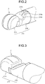
- FIG. 2 is a perspective view schematically illustrating a distal end configuration of the insertion portion of the ultrasound endoscope according to this first embodiment.
- FIG. 3 is a perspective view schematically illustrating a distal end configuration of the insertion portion of the ultrasound endoscope according to this first embodiment, and is a perspective view of the distal end configuration of the insertion portion that is viewed from an opposite direction to FIG. 2 . As illustrated in FIG.
- the distal end portion 211 includes an ultrasound functional unit 214 that holds the ultrasound transducer 7, and an endoscope functional unit 215 including an observation window 215a that causes light to enter an imaging optical system that includes an objective lens and the like, and takes in light from the outside, and an illumination window 215b being a part of an illumination optical system that collects illumination light and emits the illumination light to the outside.
- an endoscope functional unit 215 a processing tool protrusion port 215c that is communicated with the processing tool insertion path formed in the insertion portion 21, and causes a processing tool to protrude from the distal end of the insertion portion 21 is formed.
- the endoscope functional unit 215 detachably connects with the ultrasound functional unit 214 at one end, and connects to the curve portion 212 at another end.
- the processing tool insertion path is provided so that an end vicinity connecting to the processing tool protrusion port 215c inclines with respect to the longitudinal axis N of the insertion portion 21, and the processing tool protrudes from the processing tool protrusion port 215c in a direction inclining with respect to the longitudinal axis N.
- the longitudinal axis N here refers to an axis extending along the longitudinal direction of the insertion portion 21. In the curve portion 212 and the flexible tube portion 213, an axis direction varies depending on each position. Nevertheless, in the rigid distal end portion 211, the longitudinal axis N is an axis forming a fixed straight line.
- the operating unit 22 is a portion that is connected to a proximal end side of the insertion portion 21, and receives various operations from a doctor or the like. As illustrated in FIG. 1 , the operating unit 22 includes a curve knob 221 for performing a curving operation of the curve portion 212, and a plurality of operating members 222 for performing various operations. In addition, a processing tool insertion port 223 that is communicated with the processing tool insertion path, and is provided for inserting the processing tool into the processing tool insertion path is formed in the operating unit 22.
- the universal cord 23 is a cable extending from the operating unit 22, and in which a plurality of signal cables for transferring various signals, optical fibers for transferring illumination light supplied from the light source device 6, and the like are laid.
- the connector 24 is provided at a distal end of the universal cord 23.
- the connector 24 includes first to third connector portions 241 to 243 to which an ultrasound cable 31, a video cable 41, and an optical fiber cable 61 are respectively connected.
- the ultrasound observation apparatus 3 electrically-connects to the ultrasound endoscope 2 via the ultrasound cable 31 ( FIG. 1 ), outputs a pulse signal to the ultrasound endoscope 2 via the ultrasound cable 31, and inputs an echo signal from the ultrasound endoscope 2. Then, the ultrasound observation apparatus 3 performs predetermined processing on the echo signal to generate an ultrasound image.
- the endoscope observation apparatus 4 electrically-connects to the ultrasound endoscope 2 via the video cable 41 ( FIG. 1 ), and inputs an image signal from the ultrasound endoscope 2 via the video cable 41. Then, the endoscope observation apparatus 4 performs predetermined processing on the image signal to generate an endoscope image.
- the display device 5 is formed by using a liquid crystal, an organic electro luminescence (EL), a projector, a cathode ray tube (CRT), or the like, and displays the ultrasound image generated in the ultrasound observation apparatus 3, the endoscope image generated in the endoscope observation apparatus 4, and the like.
- EL organic electro luminescence
- CRT cathode ray tube
- the light source device 6 connects to the ultrasound endoscope 2 via the optical fiber cable 61 ( FIG. 1 ), and supplies, via the optical fiber cable 61, illumination light for illuminating the inside of a subject, to the ultrasound endoscope 2.
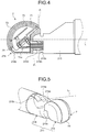
- FIG. 4 is a partially-enlarged view schematically illustrating a configuration of the ultrasound functional unit according to this first embodiment, and is a partially-enlarged view in which a plane passing through the longitudinal axis of the insertion portion 21 is assumed to be a cutting plane.
- the ultrasound transducer 7 is a convex-type ultrasound transducer as illustrated in FIG. 2 , and is a one-dimensional array (1D array) having a piezoelectric element group 71 in which a plurality of piezoelectric elements is arrayed in a line.
- the plurality of piezoelectric elements 71 is arranged along an outer surface forming a curved surface of the ultrasound transducer 7, and transmits and receives ultrasound waves on a surface including the longitudinal axis N and being parallel to the longitudinal axis N.
- the ultrasound transducer 7 includes the piezoelectric element group 71 having a prismatic shape, and including a plurality of piezoelectric elements arranged with a uniform longitudinal direction, an acoustic matching layer 72 each provided on the outer surface side of the ultrasound transducer 7 for the piezoelectric element group 71, an acoustic lens 73 provided on an opposite side to the side of the acoustic matching layer 72 that is in contact with the piezoelectric element group 71, a relay board 74 that electrically connects each piezoelectric element of the piezoelectric element group 71, and a cable into which the insertion portion 21 is inserted, and a backing material (not illustrated) provided on an opposite side to a side of the piezoelectric element group 71 that is in contact with the acoustic matching layer 72 (refer to FIG.
- the backing material fills a hollow space formed between the acoustic matching layer 72 and a wall portion having a cup shape and accommodating the relay board 74.
- a cable 74a into which the insertion portion 21 is to be inserted is connected to the relay board 74.
- the piezoelectric element converts an electrical pulse signal into an ultrasound pulse (acoustic pulse), emits the ultrasound pulse onto a subject, converts an ultrasound echo reflected by the subject, into an electrical echo signal represented by a voltage change, and outputs the electrical echo signal.
- the acoustic matching layer 72 matches acoustic impedance between a piezoelectric element and an observation target for efficiently transmitting sound (ultrasound waves) between the piezoelectric element group 71 and the observation target.
- the acoustic matching layer 72 may be formed of a plurality of layers made of materials different from each other, or may be one layer depending on the properties of the piezoelectric element and the observation target.
- the acoustic lens 73 covers the acoustic matching layer 72 and the outer surface of the wall portion.
- the acoustic lens 73 constitutes a part of the outer surface of the ultrasound transducer 7.
- the acoustic lens 73 is formed by using silicone, polymethylpentene, epoxy resin, polyetherimide, and the like.
- One surface of the acoustic lens 73 has a convex shape or a concave shape so as to have a function of stopping down ultrasound waves.
- the acoustic lens 73 emits ultrasound waves having passed through the acoustic matching layer 72, to the outside, or takes in an ultrasound echo from the outside.
- the acoustic lens 73 can be arbitrarily provided, and a configuration not including the acoustic lens 73 may be employed.
- the backing material attenuates unnecessary ultrasound vibration generated by an operation of the piezoelectric element.
- the backing material is formed by using material having a large attenuation rate, such as, for example, epoxy resin in which fillers such as alumina and zirconia are dispersed, or rubber in which the aforementioned fillers are dispersed.
- the ultrasound functional unit 214 detachably connects with the endoscope functional unit 215. More particularly, the ultrasound functional unit 214 includes a main body portion 214a that holds the ultrasound transducer 7, and a protrusion portion 214b that protrudes from the main body portion 214a, and connects with the endoscope functional unit 215.
- the endoscope functional unit 215 includes a hole portion 215d that is provided at an end portion on the opposite side to a side connecting with the curve portion 212, and is a hole connecting with the ultrasound functional unit 214, and a balloon locking portion 215e having a groove shape that can lock a balloon (not illustrated).
- the ultrasound functional unit 214 and the endoscope functional unit 215 connect to each other by the protrusion portion 214b fitting into the hole portion 215d. At this time, both units may be fixed by a known method such as adhesive agent and screwing.
- the ultrasound transducer 7 having the above configuration emits ultrasound waves onto an observation target via the acoustic matching layer 72 and the acoustic lens 73 by each piezoelectric element vibrating according to an input of a pulse signal.
- the piezoelectric elements on an opposite side to an arrangement side of the acoustic matching layer 72 and the acoustic lens 73, due to the backing material, vibration of the piezoelectric elements is attenuated, and the vibration of the piezoelectric elements is not transmitted.
- ultrasound waves reflected by the observation target are transmitted to each piezoelectric element via the acoustic matching layer 72 and the acoustic lens 73.
- the piezoelectric element vibrates according to the transmitted ultrasound waves, and the piezoelectric element converts the vibration into an electrical echo signal, and outputs, as an echo signal, the electrical echo signal to the ultrasound observation apparatus 3 via a cable (not illustrated).
- a plane P 1 (first plane) passes, in the longitudinal axis N direction of the insertion portion 21, through an end portion of the ultrasound transducer 7 near the endoscope functional unit 215 and is perpendicular to the longitudinal axis N of the insertion portion 21.
- the plane P 1 is positioned closer to a proximal end than a plane P 2 (second plane) passing through an end portion of the hole portion 215d near the ultrasound functional unit 214, the end portion being an end portion of the endoscope functional unit 215 and being a boundary between the ultrasound functional unit 214 and the endoscope functional unit 215.
- the insertion portion 21 can be formed without elongating an extension length in the longitudinal axis direction of the insertion portion 21.
- FIG. 5 is a perspective view schematically illustrating a distal end configuration of the insertion portion of the ultrasound endoscope according to this first embodiment.
- the outer surface of the ultrasound transducer 7 does not interfere with an axis L 1 extending in an extending direction of the processing tool protruding from the processing tool protrusion port 215c.
- the ultrasound transducer 7 satisfies the aforementioned positional relationship with the plane P 1 and the plane P 2 , the ultrasound transducer 7 does not interfere with an operation of the processing tool protruding from the processing tool protrusion port 215c.
- FIG. 6 is a plan view schematically illustrating a configuration of the insertion portion of the ultrasound endoscope according to this first embodiment that is viewed from a distal end side.
- an axis L 2 passing through the center of the ultrasound transducer 7 in a direction perpendicular to the longitudinal axis direction of the insertion portion 21, and being parallel to the longitudinal axis direction of the insertion portion 21 is offset with respect to an axis L 3 passing through the center of the observation window 215a, and being parallel to the longitudinal axis direction of the insertion portion 21.
- FIG. 7 is a perspective view schematically illustrating a distal end configuration of the insertion portion of the ultrasound endoscope according to this first embodiment.
- the outer surface of the ultrasound transducer 7 does not interfere with an optical axis L 4 (imaging optical axis of imaging optical system) of light entering the observation window 215a, and an optical axis L 5 of illumination light emitted by the illumination window 215b constituting a part of the illumination optical system.
- the ultrasound transducer 7 satisfies the aforementioned positional relationship with the plane P 1 and the plane P 2 , the ultrasound transducer 7 does not interfere with observation light entering the imaging optical system, and illumination light emitted from the illumination window 215b.
- the plane P 1 passing through an end portion on the endoscope functional unit 215 side of the ultrasound transducer 7, and being perpendicular to the longitudinal axis of the insertion portion 21 is positioned on the proximal end side of the plane P 2 passing through an end portion of the endoscope functional unit 215 that serves as a boundary between the ultrasound functional unit 214 and the endoscope functional unit 215, and is an end portion on the ultrasound functional unit 214 side of the hole portion 215d.
- a curvature radius of the ultrasound transducer 7 can be increased without elongating an extension length of the ultrasound transducer 7, and without causing upsizing.
- the ultrasound functional unit 214 and the endoscope functional unit 215 are separate units. Nevertheless, if the aforementioned positional relationship with the plane P 1 and the plane P 2 is satisfied, the units may be integrally provided.
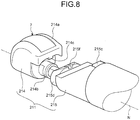
- FIG. 8 is a perspective view schematically illustrating a distal end configuration of an insertion portion of an ultrasound endoscope according to a modified example of this first embodiment.
- the main body portion 214a according to the aforementioned first embodiment is provided with a projection portion 214c, and a recessed portion 215f is provided on an outer circumferential surface of the hole portion 215d.
- FIG. 9 is a perspective view schematically illustrating a distal end configuration of an insertion portion of an ultrasound endoscope according to a second embodiment of the present invention.
- FIG. 10 is a perspective view schematically illustrating a distal end configuration of the insertion portion of the ultrasound endoscope according to this second embodiment, and is a perspective view of a distal end configuration of the insertion portion that is viewed from an opposite direction to FIG. 9 .
- the description has been given assuming that, in the distal end portion 211, the ultrasound functional unit 214 and the endoscope functional unit 215 are provided as separate units. Nevertheless, in a distal end portion 216 according to this second embodiment, an ultrasound functional unit 216a and an endoscope functional unit 216b are integrally provided.
- the distal end portion 216 includes the ultrasound functional unit 216a that holds the ultrasound transducer 7, the endoscope functional unit 216b including an observation window 216ba that causes light to enter an imaging optical system that includes an objective lens and the like, and takes in light from the outside, and an illumination window 216bb constituting a part of an illumination optical system that collects illumination light and emits the light to the outside, and a balloon locking portion 216c that is provided between the ultrasound functional unit 216a and the endoscope functional unit 216b to connect the ultrasound functional unit 216a and the endoscope functional unit 216b, and has a groove shape for locking a balloon.
- a processing tool protrusion port 216bc that is communicated with the processing tool insertion path formed in the insertion portion 21, and causes a processing tool to protrude from the distal end of the insertion portion 21 is formed.
- the endoscope functional unit 216b connects to the ultrasound functional unit 216a at one end, and connects to the curve portion 212 at another end.
- FIG. 11 is a partially-enlarged view schematically illustrating a configuration of the ultrasound functional unit according to this second embodiment, and is a partially-enlarged view in which a plane passing through the longitudinal axis N of the insertion portion 21 is assumed to be a cutting plane. As illustrated in FIG. 11
- a plane P 3 (first plane) passing through an end portion (first end portion) on the endoscope functional unit 216b side of the ultrasound transducer 7, and being perpendicular to the longitudinal axis N of the insertion portion 21 is positioned on a proximal end side of a plane P 4 (second plane) passing through an end portion (second end portion) on the ultrasound functional unit 216a side of the balloon locking portion 216c.
- the insertion portion 21 can be formed without elongating an extension length in the longitudinal axis direction of the insertion portion 21.
- FIG. 12 is a side view schematically illustrating a distal end configuration of the insertion portion of the ultrasound endoscope according to this second embodiment, and is a diagram illustrating a relationship between lengths of portions in the distal end portion 216.
- D 1 a largest diameter of the endoscope functional unit 216b
- D 2 a smallest diameter of the endoscope functional unit 216b
- Q 1 an end portion (third end portion) on a distal end side in an array direction of the piezoelectric elements of the ultrasound transducer 7
- Q 2 an end portion (first end portion) on a proximal end side
- m 1 a distance that is from the end portion Q 1 to an end portion (second end portion) on the ultrasound functional unit 216a side of the balloon locking portion 216c
- m 1 a distance between the end portions Q 1 and
- the outer surface of the ultrasound transducer 7 is provided so as not to interfere with the axis (axis L 1 ) extending in an extending direction of the processing tool protruding from the processing tool protrusion port 216bc.
- the ultrasound transducer 7 satisfies the aforementioned positional relationship with the plane P 3 and the plane P 4 , the ultrasound transducer 7 does not interfere with an operation of the processing tool protruding from the processing tool protrusion port 216bc.
- the axis (axis L 2 ) passing through the center of the ultrasound transducer 7 in a direction perpendicular to the longitudinal axis direction of the insertion portion 21, and being parallel to the longitudinal axis direction of the insertion portion 21 is provided to be offset with respect to the axis (axis L 3 ) passing through the center of the observation window 216ba, and being parallel to the longitudinal axis direction of the insertion portion 21.
- the ultrasound transducer 7 does not interfere with light entering the observation window 216ba.
- the outer surface of the ultrasound transducer 7 does not interfere with the optical axis (optical axis L 4 ) of light entering the observation window 216ba, and the optical axis (optical axis L 5 ) of illumination light emitted by the illumination window 216bb constituting a part of the illumination optical system.
- the ultrasound transducer 7 satisfies the aforementioned positional relationship with the plane P 3 and the plane P 4 , the ultrasound transducer 7 does not interfere with observation light entering the observation optical system, and illumination light emitted from the illumination window 216bb.
- the plane P 3 passes, in the longitudinal axis direction of the insertion portion 21, through an end portion near the endoscope functional unit 216b of the ultrasound transducer 7 and is perpendicular to the longitudinal axis of the insertion portion 21.
- the plane P 3 is positioned closer to the proximal end than the plane P 4 passing through an end portion of the balloon locking portion 216c near the ultrasound functional unit 216a.
- a curvature radius of the ultrasound transducer 7 can be increased without elongating an extension length of the ultrasound transducer 7, and without causing upsizing.
- an ultrasound miniature probe not having an optical system and having a thin diameter may be applied as the ultrasound endoscope.
- the ultrasound miniature probe is normally inserted into a biliary tract, biliary duct, pancreas duct, trachea, bronchus, urethra, or ureter, and is used when their adjacent organs (pancreas, lung, glandula prostatica, urinary bladder, lymph nodes, etc.) are observed.
- an external ultrasound probe that emits ultrasound waves from a body surface of a subject may be applied as an ultrasound endoscope.
- the external ultrasound probe is normally used when abdominal organs (liver, cholecystis, urinary bladder), breast (in particular, glandula mammaria), and glandula thyreoidea are observed.
- an ultrasound endoscope according to the present invention is useful in increasing a curvature radius of an ultrasound transducer without causing upsizing.
Landscapes
- Health & Medical Sciences (AREA)
- Life Sciences & Earth Sciences (AREA)
- Engineering & Computer Science (AREA)
- Surgery (AREA)
- Heart & Thoracic Surgery (AREA)
- Veterinary Medicine (AREA)
- Nuclear Medicine, Radiotherapy & Molecular Imaging (AREA)
- Pathology (AREA)
- Radiology & Medical Imaging (AREA)
- Biomedical Technology (AREA)
- Physics & Mathematics (AREA)
- Medical Informatics (AREA)
- Molecular Biology (AREA)
- Biophysics (AREA)
- Animal Behavior & Ethology (AREA)
- General Health & Medical Sciences (AREA)
- Public Health (AREA)
- Computer Vision & Pattern Recognition (AREA)
- Gynecology & Obstetrics (AREA)
- Optics & Photonics (AREA)
- Ultra Sonic Daignosis Equipment (AREA)
Abstract
Description
- The present invention relates to an ultrasound endoscope including an ultrasound transducer that emits ultrasound waves onto an observation target, receives an ultrasound echo reflected by the observation target, converts the ultrasound echo into an echo signal, and outputs the echo signal.
- For observing the property of body tissue or material that is an observation target, ultrasound waves are applied in some cases. More particularly, an ultrasound observation apparatus can acquire information related to the property of the observation target, by performing predetermined signal processing on an ultrasound echo received from an ultrasound transducer that transmits and receives ultrasound waves.
- The ultrasound transducer includes a plurality of piezoelectric elements that converts an electrical pulse signal into an ultrasound pulse (acoustic pulse), emits the ultrasound pulse onto the observation target, converts the ultrasound echo reflected by the observation target, into an electrical echo signal, and outputs the electrical echo signal. For example, by arranging a plurality of piezoelectric elements along a predetermined direction, and electrically switching an element involved in the transmission and reception, or delaying the transmission and reception of each element, an ultrasound echo is acquired from the observation target.
- There are known a plurality of types of ultrasound transducers having different ultrasound-beam transmission and reception directions, such as a convex type, a linear type, and a radial type. Among these types, a convex-type ultrasound transducer includes a plurality of piezoelectric elements arrayed along a curved surface, and each element emits an ultrasound beam in a radial direction of the curved surface (e.g., refer to Patent Literature 1). Patent Literature 1 discloses a configuration in which a convex-type ultrasound transducer is provided at a distal end of an insertion portion of an ultrasound endoscope.
- Patent Literature 1:
JP 2004-254942 A - Nevertheless, the ultrasound endoscope disclosed in Patent Literature 1 has such a problem that, if a curvature radius of the curved surface of the convex-type ultrasound transducer (curved surface passing through distal ends of a plurality of piezoelectric elements) is increased, an extension length of the ultrasound transducer with respect to a longitudinal axis direction of the insertion portion becomes long.
- The present invention has been devised in view of the foregoing, and the object of the present invention is to provide an ultrasound endoscope that can increase a curvature radius of an ultrasound transducer without causing upsizing.
- To solve the above-described problem and achieve the object, an ultrasound endoscope according to the present invention includes an insertion portion to be inserted into a subject, and includes: an ultrasound functional unit provided at a distal end of the insertion portion, the ultrasound functional unit including an ultrasound transducer configured to transmit and receive an ultrasound wave on a surface including a longitudinal axis of the insertion portion, the surface being parallel to the longitudinal axis; and an endoscope functional unit connected to the ultrasound functional unit, the endoscope functional unit at least including: a balloon locking portion having a groove shape that can lock a balloon; and an imaging optical system, wherein a first plane passes, in a direction of the longitudinal axis of the insertion portion, through an end portion of the ultrasound transducer near the endoscope functional unit, the first plane being perpendicular to the longitudinal axis of the insertion portion, and the first plane is positioned closer to a proximal end than a second plane passing through an end portion of the endoscope functional unit near the ultrasound functional unit, the end portion of the endoscope functional unit being a boundary between the ultrasound functional unit and the endoscope functional unit.
- Moreover, in the above-described ultrasound endoscope according to the present invention, the ultrasound functional unit is detachable from the endoscope functional unit.
- Moreover, the above-described ultrasound endoscope according to the present invention further includes a rotation suppression unit configured to suppress rotation of the ultrasound functional unit around an axis that is parallel to the longitudinal axis, with respect to the endoscope functional unit.
- Moreover, an ultrasound endoscope according to the present invention includes an insertion portion to be inserted into a subject, and includes: an ultrasound functional unit provided at a distal end of the insertion portion, the ultrasound functional unit including an ultrasound transducer configured to transmit and receive an ultrasound wave on a surface including a longitudinal axis of the insertion portion, and the surface being parallel to the longitudinal axis; an endoscope functional unit that at least includes an imaging optical system; and a balloon locking portion configured to connect the ultrasound functional unit and the endoscope functional unit, the balloon locking portion having a groove shape that can lock a balloon, wherein a first plane passes, in a direction of the longitudinal axis of the insertion portion, through a first end portion of the ultrasound transducer near the endoscope functional unit, the first plane being perpendicular to the longitudinal axis of the insertion portion, and the first plane is positioned closer to a proximal end than a second plane passing through a second end portion of the balloon locking portion near the ultrasound functional unit.
- Moreover, in the above-described ultrasound endoscope according to the present invention, a first distance in a direction of the longitudinal axis from a distal end of the longitudinal axis of the ultrasound functional unit to the second end portion is smaller than a second distance in the direction of the longitudinal axis between both end portions of the ultrasound functional unit.
- Moreover, in the above-described ultrasound endoscope according to the present invention, relationships represented by following formulae (1) to (4) are satisfied:




- According to the present invention, such an effect that a curvature radius of an ultrasound transducer can be increased without causing upsizing is brought about.
-
-
FIG. 1 is a diagram schematically illustrating an endoscope system according to a first embodiment of the present invention. -
FIG. 2 is a perspective view schematically illustrating a distal end configuration of an insertion portion of an ultrasound endoscope according to the first embodiment of the present invention. -
FIG. 3 is a perspective view schematically illustrating a distal end configuration of the insertion portion of the ultrasound endoscope according to the first embodiment of the present invention. -
FIG. 4 is a partially-enlarged view schematically illustrating a configuration of an ultrasound functional unit according to the first embodiment of the present invention. -
FIG. 5 is a perspective view schematically illustrating a distal end configuration of the insertion portion of the ultrasound endoscope according to the first embodiment of the present invention. -
FIG. 6 is a plan view schematically illustrating a configuration of the insertion portion of the ultrasound endoscope according to the first embodiment of the present invention that is viewed from a distal end side. -
FIG. 7 is a perspective view schematically illustrating a distal end configuration of the insertion portion of the ultrasound endoscope according to the first embodiment of the present invention. -
FIG. 8 is a perspective view schematically illustrating a distal end configuration of an insertion portion of an ultrasound endoscope according to a modified example of the first embodiment of the present invention. -
FIG. 9 is a perspective view schematically illustrating a distal end configuration of an insertion portion of an ultrasound endoscope according to a second embodiment of the present invention. -
FIG. 10 is a perspective view schematically illustrating a distal end configuration of the insertion portion of the ultrasound endoscope according to the second embodiment of the present invention. -
FIG. 11 is a partially-enlarged view schematically illustrating a configuration of an ultrasound functional unit according to the second embodiment of the present invention. -
FIG. 12 is a side view schematically illustrating a distal end configuration of the insertion portion of the ultrasound endoscope according to the second embodiment of the present invention. - A mode for carrying out the present invention (hereinafter, referred to as an embodiment) will be described below with reference to the drawings. In addition, the present invention is not limited by the embodiment to be described below. Furthermore, in the description of the drawings, the same parts are assigned the same signs.
-
FIG. 1 is a diagram schematically illustrating an endoscope system according to a first embodiment of the present invention. An endoscope system 1 is a system for performing ultrasound diagnosis of the inside of a subject such as a human, using an ultrasound endoscope. As illustrated inFIG. 1 , the endoscope system 1 includes anultrasound endoscope 2, anultrasound observation apparatus 3, anendoscope observation apparatus 4, adisplay device 5, and alight source device 6. - The
ultrasound endoscope 2 converts an electrical pulse signal received from theultrasound observation apparatus 3, into an ultrasound pulse (acoustic pulse), emits the ultrasound pulse onto a subject at its distal end portion, converts an ultrasound echo reflected by the subject, into an electrical echo signal represented by voltage change, and outputs the electrical echo signal. - The
ultrasound endoscope 2 normally includes an imaging optical system and an image sensor, is inserted into a digestive tract (esophagus, stomach, duodenum, large intestine) or a respiratory organ (trachea, bronchus) of the subject, and can perform capturing of the digestive tract or the respiratory organ. In addition, their adjacent organs (pancreas, cholecystis, biliary duct, biliary tract, lymph nodes, mediastinum organ, blood vessels, etc.) can be captured using ultrasound waves. In addition, theultrasound endoscope 2 includes a light guide that guides illumination light to be emitted onto a subject when optical capturing is performed. The light guide has a distal end portion and a proximal end portion. The distal end portion reaches a distal end of an insertion portion to be inserted into a subject of theultrasound endoscope 2. On the other hand, the proximal end portion is connected to thelight source device 6 that generates illumination light. - As illustrated in
FIG. 1 , theultrasound endoscope 2 includes aninsertion portion 21, anoperating unit 22, auniversal cord 23, and aconnector 24. Theinsertion portion 21 is a portion to be inserted into the subject. As illustrated inFIG. 1 , theinsertion portion 21 includes a rigiddistal end portion 211 that is provided on a distal end side, and holds aultrasound transducer 7, acurve portion 212 capable of curving that is connected to a proximal end side of thedistal end portion 211, and aflexible tube portion 213 having flexibility that is connected to a proximal end side of thecurve portion 212. Here, inside theinsertion portion 21, a light guide for transferring illumination light supplied from thelight source device 6, and a plurality of signal cables for transferring various signals are laid, and a processing tool insertion path for inserting a processing tool is formed, of which specific illustrations are omitted in the drawings. In addition, in this specification, theultrasound transducer 7 side of theinsertion portion 21 will be referred to as a distal end (also referred to as one end in a longitudinal axis N (refer toFIG. 4 ) direction of the insertion portion 21), and a side connecting to theoperating unit 22 will be referred to as a proximal end (also referred to as another end in the longitudinal axis N direction of the insertion portion 21). - The
ultrasound transducer 7 may be any of a convex transducer and a linear transducer. In this first embodiment, the description will be given assuming that theultrasound endoscope 2 electrically performs scanning by providing, as theultrasound transducer 7, a plurality of piezoelectric elements in an array, and electrically switching a piezoelectric element involved in transmission and reception, or delaying transmission and reception of each piezoelectric element. Nevertheless, theultrasound endoscope 2 may mechanically scan theultrasound transducer 7. A configuration of theultrasound transducer 7 will be described later. -
FIG. 2 is a perspective view schematically illustrating a distal end configuration of the insertion portion of the ultrasound endoscope according to this first embodiment.FIG. 3 is a perspective view schematically illustrating a distal end configuration of the insertion portion of the ultrasound endoscope according to this first embodiment, and is a perspective view of the distal end configuration of the insertion portion that is viewed from an opposite direction toFIG. 2 . As illustrated inFIG. 2 , thedistal end portion 211 includes an ultrasoundfunctional unit 214 that holds theultrasound transducer 7, and an endoscopefunctional unit 215 including anobservation window 215a that causes light to enter an imaging optical system that includes an objective lens and the like, and takes in light from the outside, and anillumination window 215b being a part of an illumination optical system that collects illumination light and emits the illumination light to the outside. In the endoscopefunctional unit 215, a processingtool protrusion port 215c that is communicated with the processing tool insertion path formed in theinsertion portion 21, and causes a processing tool to protrude from the distal end of theinsertion portion 21 is formed. The endoscopefunctional unit 215 detachably connects with the ultrasoundfunctional unit 214 at one end, and connects to thecurve portion 212 at another end. The processing tool insertion path is provided so that an end vicinity connecting to the processingtool protrusion port 215c inclines with respect to the longitudinal axis N of theinsertion portion 21, and the processing tool protrudes from the processingtool protrusion port 215c in a direction inclining with respect to the longitudinal axis N. The longitudinal axis N here refers to an axis extending along the longitudinal direction of theinsertion portion 21. In thecurve portion 212 and theflexible tube portion 213, an axis direction varies depending on each position. Nevertheless, in the rigiddistal end portion 211, the longitudinal axis N is an axis forming a fixed straight line. - The operating
unit 22 is a portion that is connected to a proximal end side of theinsertion portion 21, and receives various operations from a doctor or the like. As illustrated inFIG. 1 , the operatingunit 22 includes acurve knob 221 for performing a curving operation of thecurve portion 212, and a plurality of operatingmembers 222 for performing various operations. In addition, a processingtool insertion port 223 that is communicated with the processing tool insertion path, and is provided for inserting the processing tool into the processing tool insertion path is formed in the operatingunit 22. - The
universal cord 23 is a cable extending from the operatingunit 22, and in which a plurality of signal cables for transferring various signals, optical fibers for transferring illumination light supplied from thelight source device 6, and the like are laid. - The
connector 24 is provided at a distal end of theuniversal cord 23. In addition, theconnector 24 includes first tothird connector portions 241 to 243 to which anultrasound cable 31, avideo cable 41, and anoptical fiber cable 61 are respectively connected. - The
ultrasound observation apparatus 3 electrically-connects to theultrasound endoscope 2 via the ultrasound cable 31 (FIG. 1 ), outputs a pulse signal to theultrasound endoscope 2 via theultrasound cable 31, and inputs an echo signal from theultrasound endoscope 2. Then, theultrasound observation apparatus 3 performs predetermined processing on the echo signal to generate an ultrasound image. - The
endoscope observation apparatus 4 electrically-connects to theultrasound endoscope 2 via the video cable 41 (FIG. 1 ), and inputs an image signal from theultrasound endoscope 2 via thevideo cable 41. Then, theendoscope observation apparatus 4 performs predetermined processing on the image signal to generate an endoscope image. - The
display device 5 is formed by using a liquid crystal, an organic electro luminescence (EL), a projector, a cathode ray tube (CRT), or the like, and displays the ultrasound image generated in theultrasound observation apparatus 3, the endoscope image generated in theendoscope observation apparatus 4, and the like. - The
light source device 6 connects to theultrasound endoscope 2 via the optical fiber cable 61 (FIG. 1 ), and supplies, via theoptical fiber cable 61, illumination light for illuminating the inside of a subject, to theultrasound endoscope 2. - Subsequently, a configuration of the
ultrasound transducer 7 provided at the distal end of theinsertion portion 21 will be described with reference toFIGS. 2 to 4 .FIG. 4 is a partially-enlarged view schematically illustrating a configuration of the ultrasound functional unit according to this first embodiment, and is a partially-enlarged view in which a plane passing through the longitudinal axis of theinsertion portion 21 is assumed to be a cutting plane. In this first embodiment, the description will be given assuming that theultrasound transducer 7 is a convex-type ultrasound transducer as illustrated inFIG. 2 , and is a one-dimensional array (1D array) having apiezoelectric element group 71 in which a plurality of piezoelectric elements is arrayed in a line. In other words, in theultrasound transducer 7 according to this first embodiment, the plurality ofpiezoelectric elements 71 is arranged along an outer surface forming a curved surface of theultrasound transducer 7, and transmits and receives ultrasound waves on a surface including the longitudinal axis N and being parallel to the longitudinal axis N. - The
ultrasound transducer 7 includes thepiezoelectric element group 71 having a prismatic shape, and including a plurality of piezoelectric elements arranged with a uniform longitudinal direction, anacoustic matching layer 72 each provided on the outer surface side of theultrasound transducer 7 for thepiezoelectric element group 71, anacoustic lens 73 provided on an opposite side to the side of theacoustic matching layer 72 that is in contact with thepiezoelectric element group 71, arelay board 74 that electrically connects each piezoelectric element of thepiezoelectric element group 71, and a cable into which theinsertion portion 21 is inserted, and a backing material (not illustrated) provided on an opposite side to a side of thepiezoelectric element group 71 that is in contact with the acoustic matching layer 72 (refer toFIG. 4 ). The backing material fills a hollow space formed between theacoustic matching layer 72 and a wall portion having a cup shape and accommodating therelay board 74. Acable 74a into which theinsertion portion 21 is to be inserted is connected to therelay board 74. - The piezoelectric element converts an electrical pulse signal into an ultrasound pulse (acoustic pulse), emits the ultrasound pulse onto a subject, converts an ultrasound echo reflected by the subject, into an electrical echo signal represented by a voltage change, and outputs the electrical echo signal.
- The
acoustic matching layer 72 matches acoustic impedance between a piezoelectric element and an observation target for efficiently transmitting sound (ultrasound waves) between thepiezoelectric element group 71 and the observation target. Theacoustic matching layer 72 may be formed of a plurality of layers made of materials different from each other, or may be one layer depending on the properties of the piezoelectric element and the observation target. - The
acoustic lens 73 covers theacoustic matching layer 72 and the outer surface of the wall portion. Theacoustic lens 73 constitutes a part of the outer surface of theultrasound transducer 7. Theacoustic lens 73 is formed by using silicone, polymethylpentene, epoxy resin, polyetherimide, and the like. One surface of theacoustic lens 73 has a convex shape or a concave shape so as to have a function of stopping down ultrasound waves. Theacoustic lens 73 emits ultrasound waves having passed through theacoustic matching layer 72, to the outside, or takes in an ultrasound echo from the outside. Theacoustic lens 73 can be arbitrarily provided, and a configuration not including theacoustic lens 73 may be employed. - The backing material attenuates unnecessary ultrasound vibration generated by an operation of the piezoelectric element. The backing material is formed by using material having a large attenuation rate, such as, for example, epoxy resin in which fillers such as alumina and zirconia are dispersed, or rubber in which the aforementioned fillers are dispersed.
- As mentioned above, the ultrasound
functional unit 214 detachably connects with the endoscopefunctional unit 215. More particularly, the ultrasoundfunctional unit 214 includes amain body portion 214a that holds theultrasound transducer 7, and aprotrusion portion 214b that protrudes from themain body portion 214a, and connects with the endoscopefunctional unit 215. In contrast to this, the endoscopefunctional unit 215 includes ahole portion 215d that is provided at an end portion on the opposite side to a side connecting with thecurve portion 212, and is a hole connecting with the ultrasoundfunctional unit 214, and aballoon locking portion 215e having a groove shape that can lock a balloon (not illustrated). The ultrasoundfunctional unit 214 and the endoscopefunctional unit 215 connect to each other by theprotrusion portion 214b fitting into thehole portion 215d. At this time, both units may be fixed by a known method such as adhesive agent and screwing. - The
ultrasound transducer 7 having the above configuration emits ultrasound waves onto an observation target via theacoustic matching layer 72 and theacoustic lens 73 by each piezoelectric element vibrating according to an input of a pulse signal. At this time, in the piezoelectric elements, on an opposite side to an arrangement side of theacoustic matching layer 72 and theacoustic lens 73, due to the backing material, vibration of the piezoelectric elements is attenuated, and the vibration of the piezoelectric elements is not transmitted. In addition, ultrasound waves reflected by the observation target are transmitted to each piezoelectric element via theacoustic matching layer 72 and theacoustic lens 73. The piezoelectric element vibrates according to the transmitted ultrasound waves, and the piezoelectric element converts the vibration into an electrical echo signal, and outputs, as an echo signal, the electrical echo signal to theultrasound observation apparatus 3 via a cable (not illustrated). - Subsequently, the arrangement of the
ultrasound transducer 7 in the ultrasoundfunctional unit 214 will be described with reference toFIG. 4 . As illustrated inFIG. 4 , a plane P1 (first plane) passes, in the longitudinal axis N direction of theinsertion portion 21, through an end portion of theultrasound transducer 7 near the endoscopefunctional unit 215 and is perpendicular to the longitudinal axis N of theinsertion portion 21. The plane P1 is positioned closer to a proximal end than a plane P2 (second plane) passing through an end portion of thehole portion 215d near the ultrasoundfunctional unit 214, the end portion being an end portion of the endoscopefunctional unit 215 and being a boundary between the ultrasoundfunctional unit 214 and the endoscopefunctional unit 215. - For example, in the case of increasing a curvature radius of a curved surface of the ultrasound transducer 7 (curved surface passing through distal ends of a plurality of piezoelectric elements) without changing the size and the number of piezoelectric elements, even if the
ultrasound transducer 7 upsizes, if an end portion on the proximal end side of theultrasound transducer 7 is extended toward the proximal end side in the longitudinal axis N direction of theinsertion portion 21 so as to satisfy a positional relationship with the plane P1 and the plane P2, without elongating an end portion on the distal end side of theultrasound transducer 7, even if theultrasound transducer 7 upsizes, theinsertion portion 21 can be formed without elongating an extension length in the longitudinal axis direction of theinsertion portion 21. -
FIG. 5 is a perspective view schematically illustrating a distal end configuration of the insertion portion of the ultrasound endoscope according to this first embodiment. As illustrated inFIG. 5 , the outer surface of theultrasound transducer 7 does not interfere with an axis L1 extending in an extending direction of the processing tool protruding from the processingtool protrusion port 215c. Thus, if theultrasound transducer 7 satisfies the aforementioned positional relationship with the plane P1 and the plane P2, theultrasound transducer 7 does not interfere with an operation of the processing tool protruding from the processingtool protrusion port 215c. -
FIG. 6 is a plan view schematically illustrating a configuration of the insertion portion of the ultrasound endoscope according to this first embodiment that is viewed from a distal end side. As illustrated inFIG. 6 , an axis L2 passing through the center of theultrasound transducer 7 in a direction perpendicular to the longitudinal axis direction of theinsertion portion 21, and being parallel to the longitudinal axis direction of theinsertion portion 21 is offset with respect to an axis L3 passing through the center of theobservation window 215a, and being parallel to the longitudinal axis direction of theinsertion portion 21. Thus, for example, even if the outer surface of theacoustic lens 73 forms a convex shape along a direction perpendicular to the longitudinal axis direction of theinsertion portion 21, theultrasound transducer 7 does not interfere with light entering theobservation window 215a. -
FIG. 7 is a perspective view schematically illustrating a distal end configuration of the insertion portion of the ultrasound endoscope according to this first embodiment. As illustrated inFIG. 7 , the outer surface of theultrasound transducer 7 does not interfere with an optical axis L4 (imaging optical axis of imaging optical system) of light entering theobservation window 215a, and an optical axis L5 of illumination light emitted by theillumination window 215b constituting a part of the illumination optical system. Thus, if theultrasound transducer 7 satisfies the aforementioned positional relationship with the plane P1 and the plane P2, theultrasound transducer 7 does not interfere with observation light entering the imaging optical system, and illumination light emitted from theillumination window 215b. - According to this first embodiment described above, in the longitudinal axis direction of the
insertion portion 21, the plane P1 passing through an end portion on the endoscopefunctional unit 215 side of theultrasound transducer 7, and being perpendicular to the longitudinal axis of theinsertion portion 21 is positioned on the proximal end side of the plane P2 passing through an end portion of the endoscopefunctional unit 215 that serves as a boundary between the ultrasoundfunctional unit 214 and the endoscopefunctional unit 215, and is an end portion on the ultrasoundfunctional unit 214 side of thehole portion 215d. Thus, a curvature radius of theultrasound transducer 7 can be increased without elongating an extension length of theultrasound transducer 7, and without causing upsizing. - In addition, in the aforementioned first embodiment, the description has been given using the 1D array as an example. Alternatively, a 1.25D array, 1.5D array, 1.75D array, and the like, in which a plurality of piezoelectric elements (vibration portions) is arrayed in a direction (elevation direction) substantially-perpendicular to a scanning direction of the ultrasound transducer (an array direction of the piezoelectric elements in the 1D array), can also be applied. In addition, in this first embodiment, 1.25D, 1.5D, and 1.75D that are divided in the elevation direction, and acquire one ultrasound image in the scanning direction are included assuming that a plurality of piezoelectric elements is one-dimensionally arrayed.
- In addition, in the aforementioned first embodiment, the description has been given assuming that the ultrasound
functional unit 214 and the endoscopefunctional unit 215 are separate units. Nevertheless, if the aforementioned positional relationship with the plane P1 and the plane P2 is satisfied, the units may be integrally provided. -
FIG. 8 is a perspective view schematically illustrating a distal end configuration of an insertion portion of an ultrasound endoscope according to a modified example of this first embodiment. In this modified example, themain body portion 214a according to the aforementioned first embodiment is provided with aprojection portion 214c, and a recessedportion 215f is provided on an outer circumferential surface of thehole portion 215d. - More particularly, the
projection portion 214c is provided at an end portion of themain body portion 214a on a side connecting with the endoscopefunctional unit 215. In addition, the recessedportion 215f is provided on a surface that is the outer circumferential surface of thehole portion 215d, and is in contact with the ultrasoundfunctional unit 214, according to a formation position of theprojection portion 214c. Theprojection portion 214c can fit into the recessedportion 215f, and at least a side surface in a direction rotating around the longitudinal axis of theinsertion portion 21 fits thereinto with being in contact with a wall surface of the recessedportion 215f. - According to this modified example, the
main body portion 214a is provided with theprojection portion 214c, and the recessedportion 215f is provided on the outer circumferential surface of thehole portion 215d, and theprojection portion 214c fits into with being in contact with the wall surface of the recessedportion 215f, at least on the side surface in the direction rotating around the axis N being parallel to the longitudinal axis of theinsertion portion 21. Thus, the ultrasoundfunctional unit 214 and the endoscopefunctional unit 215 can be relatively positioned, and the ultrasoundfunctional unit 214 can suppress the rotation around the longitudinal axis of theinsertion portion 21. -
FIG. 9 is a perspective view schematically illustrating a distal end configuration of an insertion portion of an ultrasound endoscope according to a second embodiment of the present invention.FIG. 10 is a perspective view schematically illustrating a distal end configuration of the insertion portion of the ultrasound endoscope according to this second embodiment, and is a perspective view of a distal end configuration of the insertion portion that is viewed from an opposite direction toFIG. 9 . In the aforementioned first embodiment, the description has been given assuming that, in thedistal end portion 211, the ultrasoundfunctional unit 214 and the endoscopefunctional unit 215 are provided as separate units. Nevertheless, in adistal end portion 216 according to this second embodiment, an ultrasoundfunctional unit 216a and an endoscopefunctional unit 216b are integrally provided. - As illustrated in
FIG. 9 , thedistal end portion 216 includes the ultrasoundfunctional unit 216a that holds theultrasound transducer 7, the endoscopefunctional unit 216b including an observation window 216ba that causes light to enter an imaging optical system that includes an objective lens and the like, and takes in light from the outside, and an illumination window 216bb constituting a part of an illumination optical system that collects illumination light and emits the light to the outside, and aballoon locking portion 216c that is provided between the ultrasoundfunctional unit 216a and the endoscopefunctional unit 216b to connect the ultrasoundfunctional unit 216a and the endoscopefunctional unit 216b, and has a groove shape for locking a balloon. In the endoscopefunctional unit 216b, a processing tool protrusion port 216bc that is communicated with the processing tool insertion path formed in theinsertion portion 21, and causes a processing tool to protrude from the distal end of theinsertion portion 21 is formed. The endoscopefunctional unit 216b connects to the ultrasoundfunctional unit 216a at one end, and connects to thecurve portion 212 at another end. - Subsequently, the arrangement of the
ultrasound transducer 7 in the ultrasoundfunctional unit 216a will be described with reference toFIG. 11. FIG. 11 is a partially-enlarged view schematically illustrating a configuration of the ultrasound functional unit according to this second embodiment, and is a partially-enlarged view in which a plane passing through the longitudinal axis N of theinsertion portion 21 is assumed to be a cutting plane. As illustrated inFIG. 11 , in the longitudinal axis N direction of theinsertion portion 21, a plane P3 (first plane) passing through an end portion (first end portion) on the endoscopefunctional unit 216b side of theultrasound transducer 7, and being perpendicular to the longitudinal axis N of theinsertion portion 21 is positioned on a proximal end side of a plane P4 (second plane) passing through an end portion (second end portion) on the ultrasoundfunctional unit 216a side of theballoon locking portion 216c. - For example, in the case of increasing a curvature radius of a curved surface of the ultrasound transducer 7 (curved surface passing through distal ends of a plurality of piezoelectric elements) without changing the size and the number of piezoelectric elements, if an end portion on the proximal end side of the
ultrasound transducer 7 is extended toward the proximal end side of theinsertion portion 21 so as to satisfy a positional relationship with the plane P3 and the plane P4, without elongating an end portion on the distal end side of theultrasound transducer 7, even if theultrasound transducer 7 upsizes, theinsertion portion 21 can be formed without elongating an extension length in the longitudinal axis direction of theinsertion portion 21. -
FIG. 12 is a side view schematically illustrating a distal end configuration of the insertion portion of the ultrasound endoscope according to this second embodiment, and is a diagram illustrating a relationship between lengths of portions in thedistal end portion 216. When a largest diameter of the endoscope functional unit 216b is denoted by D1, a smallest diameter of the endoscope functional unit 216b is denoted by D2, an end portion (third end portion) on a distal end side in an array direction of the piezoelectric elements of the ultrasound transducer 7 is denoted by Q1, an end portion (first end portion) on a proximal end side is denoted by Q2, a distance that is from the end portion Q1 to an end portion (second end portion) on the ultrasound functional unit 216a side of the balloon locking portion 216c, and is a distance (first distance) in the longitudinal axis direction of the insertion portion 21 is denoted by m1, a distance between the end portions Q1 and Q2 is denoted by m2, a distance (second distance) in the longitudinal axis direction of the insertion portion 21 between the end portions Q1 and Q2 is denoted by m3, a distance that is from the end portion Q1 to the end portion of the ultrasound transducer 7, and is the largest distance in a direction perpendicular to the longitudinal axis N direction of the insertion portion 21 is denoted by m4, a curvature radius of the curved surface of the ultrasound transducer 7 (curved surface passing through distal ends of a plurality of piezoelectric elements) is denoted by R, an angle formed by the end portions Q1 and Q2, and the center of curvature of the curved surface of the ultrasound transducer 7 is denoted by θ1, and an angle formed by a straight line being parallel to the longitudinal axis direction of the insertion portion 21, and a straight line passing through the end portions Q1 and Q2 is denoted by θ2, relationships represented by the following formulae (1) to (4) are satisfied.


- In addition, as in the aforementioned first embodiment, the outer surface of the
ultrasound transducer 7 is provided so as not to interfere with the axis (axis L1) extending in an extending direction of the processing tool protruding from the processing tool protrusion port 216bc. Thus, if theultrasound transducer 7 satisfies the aforementioned positional relationship with the plane P3 and the plane P4, theultrasound transducer 7 does not interfere with an operation of the processing tool protruding from the processing tool protrusion port 216bc. - In addition, the axis (axis L2) passing through the center of the
ultrasound transducer 7 in a direction perpendicular to the longitudinal axis direction of theinsertion portion 21, and being parallel to the longitudinal axis direction of theinsertion portion 21 is provided to be offset with respect to the axis (axis L3) passing through the center of the observation window 216ba, and being parallel to the longitudinal axis direction of theinsertion portion 21. Thus, for example, even if the outer surface of theacoustic lens 73 forms a convex shape along a direction perpendicular to the longitudinal axis direction of theinsertion portion 21, theultrasound transducer 7 does not interfere with light entering the observation window 216ba. - In addition, the outer surface of the
ultrasound transducer 7 does not interfere with the optical axis (optical axis L4) of light entering the observation window 216ba, and the optical axis (optical axis L5) of illumination light emitted by the illumination window 216bb constituting a part of the illumination optical system. Thus, if theultrasound transducer 7 satisfies the aforementioned positional relationship with the plane P3 and the plane P4, theultrasound transducer 7 does not interfere with observation light entering the observation optical system, and illumination light emitted from the illumination window 216bb. - According to this second embodiment described above, the plane P3 passes, in the longitudinal axis direction of the
insertion portion 21, through an end portion near the endoscopefunctional unit 216b of theultrasound transducer 7 and is perpendicular to the longitudinal axis of theinsertion portion 21. The plane P3 is positioned closer to the proximal end than the plane P4 passing through an end portion of theballoon locking portion 216c near the ultrasoundfunctional unit 216a. Thus, a curvature radius of theultrasound transducer 7 can be increased without elongating an extension length of theultrasound transducer 7, and without causing upsizing. - Modes for carrying out the present invention have been described so far. Nevertheless, the present invention is not to be limited only by the aforementioned embodiments and modified example. The present invention is not limited to the above-described embodiments and modified example, and can include various embodiments without departing from the technical ideas described in the claims. In addition, the configurations in the embodiments and the modified example may be appropriately combined.
- In addition, an ultrasound miniature probe not having an optical system and having a thin diameter may be applied as the ultrasound endoscope. The ultrasound miniature probe is normally inserted into a biliary tract, biliary duct, pancreas duct, trachea, bronchus, urethra, or ureter, and is used when their adjacent organs (pancreas, lung, glandula prostatica, urinary bladder, lymph nodes, etc.) are observed.
- In addition, an external ultrasound probe that emits ultrasound waves from a body surface of a subject may be applied as an ultrasound endoscope. The external ultrasound probe is normally used when abdominal organs (liver, cholecystis, urinary bladder), breast (in particular, glandula mammaria), and glandula thyreoidea are observed.
- As described above, an ultrasound endoscope according to the present invention is useful in increasing a curvature radius of an ultrasound transducer without causing upsizing.
-
- 1
- ENDOSCOPE SYSTEM
- 2
- ULTRASOUND ENDOSCOPE
- 3
- ULTRASOUND OBSERVATION APPARATUS
- 4
- ENDOSCOPE OBSERVATION APPARATUS
- 5
- DISPLAY DEVICE
- 6
- LIGHT SOURCE DEVICE
- 7
- ULTRASOUND TRANSDUCER
- 21
- INSERTION PORTION
- 22
- OPERATING UNIT
- 23
- UNIVERSAL CORD
- 24
- CONNECTOR
- 31
- ULTRASOUND CABLE
- 41
- VIDEO CABLE
- 61
- OPTICAL FIBER CABLE
- 71
- PIEZOELECTRIC ELEMENT GROUP
- 72
- ACOUSTIC MATCHING LAYER
- 73
- ACOUSTIC LENS
- 74
- RELAY BOARD
- 211,
- 216 DISTAL END PORTION
- 212
- CURVE PORTION
- 213
- FLEXIBLE TUBE PORTION
- 214,
- 216a ULTRASOUND FUNCTIONAL UNIT
- 214a
- MAIN BODY PORTION
- 214b
- PROTRUSION PORTION
- 214c
- PROJECTION PORTION
- 215, 216b
- ENDOSCOPE FUNCTIONAL UNIT
- 215a, 216ba
- OBSERVATION WINDOW
- 215b, 216bb
- ILLUMINATION WINDOW
- 215c, 216bc
- PROCESSING TOOL PROTRUSION PORT
- 215d
- HOLE PORTION
- 215e, 216c
- BALLOON LOCKING PORTION
- 215f
- RECESSED PORTION
- 221
- CURVE KNOB
- 222
- OPERATING MEMBER
- 223
- PROCESSING TOOL INSERTION PORT
- 241
- FIRST CONNECTOR PORTION
- 242
- SECOND CONNECTOR PORTION
- 243
- THIRD CONNECTOR PORTION
Claims (6)
- An ultrasound endoscope including an insertion portion to be inserted into a subject, the ultrasound endoscope comprising:an ultrasound functional unit provided at a distal end of the insertion portion, the ultrasound functional unit including an ultrasound transducer configured to transmit and receive an ultrasound wave on a surface including a longitudinal axis of the insertion portion, the surface being parallel to the longitudinal axis; andan endoscope functional unit connected to the ultrasound functional unit, the endoscope functional unit at least including: a balloon locking portion having a groove shape that can lock a balloon; and an imaging optical system,wherein a first plane passes, in a direction of the longitudinal axis of the insertion portion, through an end portion of the ultrasound transducer near the endoscope functional unit, the first plane being perpendicular to the longitudinal axis of the insertion portion, andthe first plane is positioned closer to a proximal end than a second plane passing through an end portion of the endoscope functional unit near the ultrasound functional unit, the end portion of the endoscope functional unit being a boundary between the ultrasound functional unit and the endoscope functional unit.
- The ultrasound endoscope according to claim 1, wherein the ultrasound functional unit is detachable from the endoscope functional unit.
- The ultrasound endoscope according to claim 1 or 2, further comprising a rotation suppression unit configured to suppress rotation of the ultrasound functional unit around an axis that is parallel to the longitudinal axis, with respect to the endoscope functional unit.
- An ultrasound endoscope including an insertion portion to be inserted into a subject, the ultrasound endoscope comprising:an ultrasound functional unit provided at a distal end of the insertion portion, the ultrasound functional unit including an ultrasound transducer configured to transmit and receive an ultrasound wave on a surface including a longitudinal axis of the insertion portion, and the surface being parallel to the longitudinal axis;an endoscope functional unit that at least includes an imaging optical system; anda balloon locking portion configured to connect the ultrasound functional unit and the endoscope functional unit, the balloon locking portion having a groove shape that can lock a balloon,wherein a first plane passes, in a direction of the longitudinal axis of the insertion portion, through a first end portion of the ultrasound transducer near the endoscope functional unit, the first plane being perpendicular to the longitudinal axis of the insertion portion, andthe first plane is positioned closer to a proximal end than a second plane passing through a second end portion of the balloon locking portion near the ultrasound functional unit.
- The ultrasound endoscope according to claim 4, wherein a first distance in a direction of the longitudinal axis from a distal end of the longitudinal axis of the ultrasound functional unit to the second end portion is smaller than a second distance in the direction of the longitudinal axis between both end portions of the ultrasound functional unit.
- The ultrasound endoscope according to claim 4, relationships represented by following formulae (1) to (4) are satisfied:




where a distance in a direction of the longitudinal axis from a third end portion on a distal end side of the longitudinal axis of the ultrasound functional unit to the second end portion is denoted by m1, a distance between the first and third end portions is denoted by m2, a distance in the direction of the longitudinal axis between the first and third end portions is denoted by m3, a distance that is a largest distance in a direction perpendicular to the longitudinal axis from the third end portion to an end portion of the ultrasound transducer is denoted by m4, a curvature radius of a curved surface of the ultrasound transducer is denoted by R, an angle formed by the second and third end portions and a center of curvature of the curved surface of the ultrasound transducer is denoted by θ1, and an angle formed by a straight line being parallel to the longitudinal axis and a straight line passing through the second and third end portions is denoted by θ2.
Applications Claiming Priority (2)
| Application Number | Priority Date | Filing Date | Title |
|---|---|---|---|
| JP2015126052 | 2015-06-23 | ||
| PCT/JP2016/060836 WO2016208250A1 (en) | 2015-06-23 | 2016-03-31 | Ultrasonic endoscope |
Publications (2)
| Publication Number | Publication Date |
|---|---|
| EP3315077A1 true EP3315077A1 (en) | 2018-05-02 |
| EP3315077A4 EP3315077A4 (en) | 2018-12-05 |
Family
ID=57585490
Family Applications (1)
| Application Number | Title | Priority Date | Filing Date |
|---|---|---|---|
| EP16814021.8A Withdrawn EP3315077A4 (en) | 2015-06-23 | 2016-03-31 | Ultrasonic endoscope |
Country Status (5)
| Country | Link |
|---|---|
| US (1) | US11684340B2 (en) |
| EP (1) | EP3315077A4 (en) |
| JP (1) | JP6197145B2 (en) |
| CN (1) | CN107708573B (en) |
| WO (1) | WO2016208250A1 (en) |
Families Citing this family (5)
| Publication number | Priority date | Publication date | Assignee | Title |
|---|---|---|---|---|
| JP6741637B2 (en) * | 2017-09-20 | 2020-08-19 | オリンパス株式会社 | Ultrasound endoscope |
| US11547277B2 (en) * | 2018-04-12 | 2023-01-10 | Endosound, Inc. | Steerable ultrasound attachment for endoscope |
| US12096915B2 (en) * | 2019-03-11 | 2024-09-24 | Gyrus Acmi, Inc. | Sheath location indicator and overextension preventer |
| WO2021193404A1 (en) * | 2020-03-26 | 2021-09-30 | 富士フイルム株式会社 | Ultrasonic endoscope |
| JP7663465B2 (en) * | 2021-09-27 | 2025-04-16 | 富士フイルム株式会社 | Balloon for ultrasonic endoscope |
Family Cites Families (19)
| Publication number | Priority date | Publication date | Assignee | Title |
|---|---|---|---|---|
| JPS62227334A (en) * | 1986-03-28 | 1987-10-06 | 株式会社東芝 | Ultrasonic endoscope |
| US5191890A (en) | 1991-04-22 | 1993-03-09 | Interspec, Inc. | Ultrasonic probe assembly |
| CN1224626A (en) * | 1998-01-25 | 1999-08-04 | 王芷龙 | Endoscope type inserted supersonic cure probe |
| JP3894092B2 (en) * | 2002-10-18 | 2007-03-14 | フジノン株式会社 | Ultrasound endoscope |
| JP2004254942A (en) | 2003-02-26 | 2004-09-16 | Pentax Corp | Ultrasound endoscope |
| JP4716500B2 (en) * | 2005-11-21 | 2011-07-06 | Hoya株式会社 | Ultrasound endoscope tip |
| JP5073415B2 (en) * | 2006-08-28 | 2012-11-14 | オリンパスメディカルシステムズ株式会社 | Ultrasound endoscope |
| JP4422733B2 (en) * | 2007-02-02 | 2010-02-24 | オリンパスメディカルシステムズ株式会社 | Ultrasonic diagnostic equipment |
| JP5329065B2 (en) * | 2007-09-28 | 2013-10-30 | 富士フイルム株式会社 | Ultrasonic probe |
| JP5468958B2 (en) * | 2010-03-30 | 2014-04-09 | 富士フイルム株式会社 | Intracorporeal ultrasound system |
| WO2012160892A1 (en) * | 2011-05-20 | 2012-11-29 | オリンパスメディカルシステムズ株式会社 | Ultrasonic endoscope |
| JP2012245061A (en) * | 2011-05-25 | 2012-12-13 | Olympus Medical Systems Corp | Ultrasonic endoscope |
| JP5984525B2 (en) * | 2011-06-24 | 2016-09-06 | オリンパス株式会社 | Ultrasonic observation equipment |
| WO2013077101A1 (en) * | 2011-11-24 | 2013-05-30 | オリンパスメディカルシステムズ株式会社 | Ultrasonic probe |
| JP5253693B1 (en) * | 2011-12-08 | 2013-07-31 | オリンパスメディカルシステムズ株式会社 | Ultrasonic probe |
| JP5379249B2 (en) * | 2012-01-13 | 2013-12-25 | 富士フイルム株式会社 | Tissue collection device |
| JP6024120B2 (en) * | 2012-02-24 | 2016-11-09 | セイコーエプソン株式会社 | Ultrasonic probe, probe head, electronic device and diagnostic device |
| JP5399594B1 (en) * | 2012-08-27 | 2014-01-29 | オリンパスメディカルシステムズ株式会社 | Ultrasound endoscope |
| CN104640507B (en) * | 2013-08-22 | 2017-04-19 | 奥林巴斯株式会社 | Ultrasound endoscope and ultrasound balloon for endoscope |
-
2016
- 2016-03-31 CN CN201680036931.4A patent/CN107708573B/en active Active
- 2016-03-31 WO PCT/JP2016/060836 patent/WO2016208250A1/en not_active Ceased
- 2016-03-31 JP JP2017513575A patent/JP6197145B2/en active Active
- 2016-03-31 EP EP16814021.8A patent/EP3315077A4/en not_active Withdrawn
-
2017
- 2017-12-14 US US15/841,512 patent/US11684340B2/en active Active
Also Published As
| Publication number | Publication date |
|---|---|
| JPWO2016208250A1 (en) | 2017-06-29 |
| CN107708573B (en) | 2020-10-09 |
| EP3315077A4 (en) | 2018-12-05 |
| US11684340B2 (en) | 2023-06-27 |
| JP6197145B2 (en) | 2017-09-13 |
| US20180168541A1 (en) | 2018-06-21 |
| CN107708573A (en) | 2018-02-16 |
| WO2016208250A1 (en) | 2016-12-29 |
Similar Documents
| Publication | Publication Date | Title |
|---|---|---|
| JP4618410B2 (en) | Ultrasound endoscope | |
| US11684340B2 (en) | Ultrasound endoscope | |
| US11793489B2 (en) | Ultrasound endoscope with flexure relay substrate | |
| WO2016175050A1 (en) | Ultrasonic transducer and ultrasonic probe | |
| US11903758B2 (en) | Ultrasonic endoscope | |
| WO2018230274A1 (en) | Endoscope | |
| US10869649B2 (en) | Ultrasound transducer module and ultrasound endoscope | |
| US20190000417A1 (en) | Endoscope | |
| US20180098688A1 (en) | Lens unit and endoscope | |
| JP6697962B2 (en) | Ultrasonic transducer and ultrasonic endoscope | |
| JP2017074231A (en) | Method of manufacturing ultrasonic endoscope and ultrasonic endoscope | |
| JP2023128309A (en) | Endoscope | |
| US11944496B2 (en) | Ultrasound endoscope | |
| JP4647968B2 (en) | Ultrasound endoscope | |
| US20180271490A1 (en) | Ultrasound transducer unit, ultrasound probe, and method of producing ultrasound transducer unit | |
| JP4488203B2 (en) | Ultrasound endoscope | |
| JPWO2020152791A1 (en) | Endoscopic ultrasound and endoscopy system | |
| JP2017225746A (en) | Endoscope | |
| WO2017150461A1 (en) | Ultrasonic probe unit, ultrasonic endoscope, and method for manufacturing ultrasonic probe unit | |
| CN116687318A (en) | Endoscope with a lens | |
| JP2006158481A (en) | Ultrasonic endoscope | |
| WO2018230502A1 (en) | Ultrasonic endoscope |
Legal Events
| Date | Code | Title | Description |
|---|---|---|---|
| STAA | Information on the status of an ep patent application or granted ep patent |
Free format text: STATUS: THE INTERNATIONAL PUBLICATION HAS BEEN MADE |
|
| PUAI | Public reference made under article 153(3) epc to a published international application that has entered the european phase |
Free format text: ORIGINAL CODE: 0009012 |
|
| STAA | Information on the status of an ep patent application or granted ep patent |
Free format text: STATUS: REQUEST FOR EXAMINATION WAS MADE |
|
| 17P | Request for examination filed |
Effective date: 20180122 |
|
| AK | Designated contracting states |
Kind code of ref document: A1 Designated state(s): AL AT BE BG CH CY CZ DE DK EE ES FI FR GB GR HR HU IE IS IT LI LT LU LV MC MK MT NL NO PL PT RO RS SE SI SK SM TR |
|
| AX | Request for extension of the european patent |
Extension state: BA ME |
|
| DAV | Request for validation of the european patent (deleted) | ||
| DAX | Request for extension of the european patent (deleted) | ||
| A4 | Supplementary search report drawn up and despatched |
Effective date: 20181102 |
|
| RIC1 | Information provided on ipc code assigned before grant |
Ipc: A61B 8/12 20060101ALI20181026BHEP Ipc: A61B 1/00 20060101AFI20181026BHEP Ipc: A61B 8/00 20060101ALI20181026BHEP |
|
| STAA | Information on the status of an ep patent application or granted ep patent |
Free format text: STATUS: EXAMINATION IS IN PROGRESS |
|
| 17Q | First examination report despatched |
Effective date: 20190523 |
|
| STAA | Information on the status of an ep patent application or granted ep patent |
Free format text: STATUS: THE APPLICATION HAS BEEN WITHDRAWN |
|
| 18W | Application withdrawn |
Effective date: 20190909 |