EP3315069A1 - Method for determination of an analyte concentration in a body fluid and analyte concentration measurement device - Google Patents
Method for determination of an analyte concentration in a body fluid and analyte concentration measurement device Download PDFInfo
- Publication number
- EP3315069A1 EP3315069A1 EP16195524.0A EP16195524A EP3315069A1 EP 3315069 A1 EP3315069 A1 EP 3315069A1 EP 16195524 A EP16195524 A EP 16195524A EP 3315069 A1 EP3315069 A1 EP 3315069A1
- Authority
- EP
- European Patent Office
- Prior art keywords
- test element
- measuring
- body portion
- measuring values
- proximity sensor
- Prior art date
- Legal status (The legal status is an assumption and is not a legal conclusion. Google has not performed a legal analysis and makes no representation as to the accuracy of the status listed.)
- Withdrawn
Links
Images
Classifications
-
- G—PHYSICS
- G01—MEASURING; TESTING
- G01N—INVESTIGATING OR ANALYSING MATERIALS BY DETERMINING THEIR CHEMICAL OR PHYSICAL PROPERTIES
- G01N33/00—Investigating or analysing materials by specific methods not covered by groups G01N1/00 - G01N31/00
- G01N33/48—Biological material, e.g. blood, urine; Haemocytometers
- G01N33/483—Physical analysis of biological material
- G01N33/487—Physical analysis of biological material of liquid biological material
- G01N33/48785—Electrical and electronic details of measuring devices for physical analysis of liquid biological material not specific to a particular test method, e.g. user interface or power supply
-
- A—HUMAN NECESSITIES
- A61—MEDICAL OR VETERINARY SCIENCE; HYGIENE
- A61B—DIAGNOSIS; SURGERY; IDENTIFICATION
- A61B5/00—Measuring for diagnostic purposes; Identification of persons
- A61B5/145—Measuring characteristics of blood in vivo, e.g. gas concentration, pH value; Measuring characteristics of body fluids or tissues, e.g. interstitial fluid, cerebral tissue
- A61B5/14532—Measuring characteristics of blood in vivo, e.g. gas concentration, pH value; Measuring characteristics of body fluids or tissues, e.g. interstitial fluid, cerebral tissue for measuring glucose, e.g. by tissue impedance measurement
-
- A—HUMAN NECESSITIES
- A61—MEDICAL OR VETERINARY SCIENCE; HYGIENE
- A61B—DIAGNOSIS; SURGERY; IDENTIFICATION
- A61B10/00—Other methods or instruments for diagnosis, e.g. instruments for taking a cell sample, for biopsy, for vaccination diagnosis; Sex determination; Ovulation-period determination; Throat striking implements
- A61B10/0045—Devices for taking samples of body liquids
-
- A—HUMAN NECESSITIES
- A61—MEDICAL OR VETERINARY SCIENCE; HYGIENE
- A61B—DIAGNOSIS; SURGERY; IDENTIFICATION
- A61B5/00—Measuring for diagnostic purposes; Identification of persons
- A61B5/0059—Measuring for diagnostic purposes; Identification of persons using light, e.g. diagnosis by transillumination, diascopy, fluorescence
-
- A—HUMAN NECESSITIES
- A61—MEDICAL OR VETERINARY SCIENCE; HYGIENE
- A61B—DIAGNOSIS; SURGERY; IDENTIFICATION
- A61B5/00—Measuring for diagnostic purposes; Identification of persons
- A61B5/145—Measuring characteristics of blood in vivo, e.g. gas concentration, pH value; Measuring characteristics of body fluids or tissues, e.g. interstitial fluid, cerebral tissue
- A61B5/1455—Measuring characteristics of blood in vivo, e.g. gas concentration, pH value; Measuring characteristics of body fluids or tissues, e.g. interstitial fluid, cerebral tissue using optical sensors, e.g. spectral photometrical oximeters
- A61B5/14551—Measuring characteristics of blood in vivo, e.g. gas concentration, pH value; Measuring characteristics of body fluids or tissues, e.g. interstitial fluid, cerebral tissue using optical sensors, e.g. spectral photometrical oximeters for measuring blood gases
- A61B5/14552—Details of sensors specially adapted therefor
-
- A—HUMAN NECESSITIES
- A61—MEDICAL OR VETERINARY SCIENCE; HYGIENE
- A61B—DIAGNOSIS; SURGERY; IDENTIFICATION
- A61B2562/00—Details of sensors; Constructional details of sensor housings or probes; Accessories for sensors
- A61B2562/02—Details of sensors specially adapted for in-vivo measurements
- A61B2562/0257—Proximity sensors
-
- A—HUMAN NECESSITIES
- A61—MEDICAL OR VETERINARY SCIENCE; HYGIENE
- A61B—DIAGNOSIS; SURGERY; IDENTIFICATION
- A61B5/00—Measuring for diagnostic purposes; Identification of persons
- A61B5/15—Devices for taking samples of blood
- A61B5/151—Devices specially adapted for taking samples of capillary blood, e.g. by lancets, needles or blades
- A61B5/15101—Details
-
- A—HUMAN NECESSITIES
- A61—MEDICAL OR VETERINARY SCIENCE; HYGIENE
- A61B—DIAGNOSIS; SURGERY; IDENTIFICATION
- A61B5/00—Measuring for diagnostic purposes; Identification of persons
- A61B5/15—Devices for taking samples of blood
- A61B5/157—Devices characterised by integrated means for measuring characteristics of blood
-
- G—PHYSICS
- G01—MEASURING; TESTING
- G01N—INVESTIGATING OR ANALYSING MATERIALS BY DETERMINING THEIR CHEMICAL OR PHYSICAL PROPERTIES
- G01N21/00—Investigating or analysing materials by the use of optical means, i.e. using sub-millimetre waves, infrared, visible or ultraviolet light
- G01N21/75—Systems in which material is subjected to a chemical reaction, the progress or the result of the reaction being investigated
- G01N21/77—Systems in which material is subjected to a chemical reaction, the progress or the result of the reaction being investigated by observing the effect on a chemical indicator
- G01N21/78—Systems in which material is subjected to a chemical reaction, the progress or the result of the reaction being investigated by observing the effect on a chemical indicator producing a change of colour
Definitions
- the invention concerns a method for determination of an analyte concentration in a body fluid.
- the invention further concerns an analyte concentration measurement device.
- test elements can be provided as chemistry fields on a test tape, which is loadable into the meter in the form of a replaceable tape cassette.
- the user has no need to take care of the disposal of each single test element.
- the instrument is generally used by patients outside a laboratory environment, and therefore the measurement may be susceptible to non-intended user handling. In extreme cases of user handling scenarios, significant measurement deviations may occur.
- a proximity sensor module is configured to detect the presence of a user's body in order to switch the meter from standby to active mode.
- US 2015/0238131 A1 proposes to employ a proximity sensor to determine whether a body part of a user protrudes by a required amount within a housing aperture such that a lancing and blood collecting operation will be successful with a high degree of confidence.
- This document is not concerned with instrument handling during the ultimate measurement procedure, as the sample handling and processing is carried out in a fully automated way inside the housing.
- the object of the invention is to further improve the known measuring methods and systems to enhance the accuracy and precision of the measurement results by controlled user handling during the data acquisition phase or detection phase.
- the invention is based on the idea of preventing measurements from being distorted by the presence of a body part.
- a method for determination of an analyte and specifically glucose in a body fluid is proposed according to the invention which comprises the steps of:
- a warning is provided to the user upon sensing the presence of the body portion in the monitored space. Such a warning may contribute to optimization of user handling.
- Another improvement in this direction provides for measuring a time interval of presence of the body portion in the monitored space, and for aborting the detection of measuring values and/or providing an error message to the user after a predetermined length of the time interval.
- a wetting of the test element with body fluid is detected, and measuring of the time interval is started at the point in time when detecting the wetting.
- the length of the time interval is in the range of 0,5 to 2 s.
- the detection of measuring values is completed only if the body portion is not present in the monitored space.
- the output signal of the proximity sensor is made available as an input for a processor unit of the meter during processing of the measuring values.
- the proximity sensor For a dedicated discrimination of a problematic proximity it is advantageous to configure the proximity sensor such that the monitored space includes a cuboid in the size of at least 1 x 1 x 5 mm, preferably at least 3 x 3 x 10 mm, where the long side of the cuboid is perpendicular to a surface of the test element.
- the output signal of the proximity sensor is provided as a digital value indicating solely the presence or absence of the body portion in the monitored space.
- the detection of measuring values comprises an initial measuring phase for measuring a blank value on the test element prior to body fluid application, an intermediate measuring phase for tracking a development of the measuring values, and a final measuring phase for determining an end value which is characteristic for a quantity of the analyte.
- a further improvement in this connection comprises transporting the test element on a transport tape over a deflection tip as a sample application site, and arranging the proximity sensor adjacent or in close proximity to the deflection tip.
- a still further improvement provides that the body fluid is applied on a freely accessible application side of the test element, and the measuring values are detected by scanning a back side of the test element opposite to the application side.
- an analyte concentration measurement device in particular for blood glucose determination, comprising a handheld meter adapted to provide a disposable test element having a reaction area at an application site for applying body fluid from a user's body portion, a preferably photometric detection unit operable for detecting measuring values on or from the reaction area of the test element, and a proximity sensor disposed within the meter to sense the presence of the body portion in a monitored space in proximity to the reaction area of the test element, wherein a processor unit of the meter is configured for
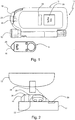
- FIG. 1 an exemplary embodiment of a medical analyte testing system for testing an analyte in a body fluid, specifically glucose in a blood sample is shown.
- the system 10 at least comprises a portable blood glucose meter 12 adapted to receive a disposable test tape cassette 14 (shown separately) which can be inserted into a compartment of the meter 12.
- a tip 16 of the inserted tape cassette 14 is accessible to the user upon opening a tip cover 18.
- the tape cassette 14 serves as a test magazine, as a plurality of test elements 20 is provided on a spoolable transport tape for successive use on the tip 16.
- the handheld meter 12 is provided with a photometric measuring unit 22 and a processor unit 24 (electronic micro-processor) for determining the concentration of the analyte from the measured values.
- the measuring result and other information can be displayed to the user on a display 24.
- the meter 12 is further provided with a proximity sensor 28 to detect the presence of a body part during critical measuring phases, thus allowing to control user handling.
- a lancing aid 30 is attached to the meter 12 for simplifying lancing of a body part in order to sample blood.
- Fig. 2 depicts a handling situation in a partial cross section of the system 10 transverse to the tip 16 of the inserted tape cassette 14.
- the user applies a drop of blood from his finger 32 to a top side of the active test element 22 provided on the tip 16.
- the test element 22 is formed by a layered chemistry field on the transport tape 34 which is responsive to the analyte by a color change.
- the measuring unit 22 provided as a reflectometer allows a measurement of the analyte concentration by optical scanning the rear side of test element 22 through the transparent transport tape 34.
- the measurement may be biased by the presence of the finger 32 which appears to the reflectometer as a dark background behind the incompletely opaque chemistry field. This influence increases with decreasing distance to the critical test field area.
- continued finger pressure on the test element 22 after sample application may lead to an unwanted modification of the layered test structure, specifically if a covering net provided for sample spreading is impressed into the chemistry field such that the optical measurement is impaired thereby.
- the proximity sensor 28 is configured to sense the presence of the body portion in a monitored space 36 in proximity to the test element 22.
- the proximity sensor 28 is placed laterally to the tape 34 adjacent to the tip 16.
- the favored solid angle that will be surveilled by the proximity sensor 28 should be as much as possible restricted. It should be ensured that the sensor does not detect objects outside a specified detection area, especially any support surface like e.g. a table. Ideally, the monitored space 36 should include a cuboid in the size of approximately 3 x 3 x 10 mm, where the long side of the cuboid is perpendicular to the top side of the test element 20. Furthermore, the optical analyte measuring unit 22 should not be disturbed by the proximity sensor 28.
- the proximity sensor 28 should deliver a digital signal indicating solely the following cases:
- the proximity sensor 28 may be formed as a kind of photometric sensor that can detect any kind of object.
- the working principle may be similar to that of the analyte measuring unit: Somehow modulated light is send out by a light source (LED). Any reflected light is collected by a photo detector. Depending on the amount of reflected light an analog signal is created. Via a set threshold the digital discrimination between absence and presence of an object is made.
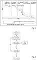
- the measuring process may be divided in various measuring phases.
- the time diagram shows measuring values on a test element provided by using a main light source (symbol x) and at least one auxiliary light source (symbol o) of the measuring unit 22.
- a blank value is detected as a double-measurement on the yet unused test element 20 prior to sample application.
- the auxiliary light source is powered to enable wetting detection preferably at a different wavelength.
- consecutive measuring values are registered with a given sampling rate of e.g. 5 Hz to enable recognition of the wetting of the test element 22 due to sample application by the user. Such wetting leads to a signal decrease below a predetermined detection threshold.
- a predetermined waiting time should be observed in phase III.
- phase IV the chemical reaction due to the presence of the analyte can be tracked in phase IV, where the reaction product leads to an increasing darkening and hence to less reflected light.
- the kinetic curve exhibits an asymptotic behavior, such that a given stop criterion is reached after a plurality of measurement readings.
- phase V an end value is recorded, eventually followed by a control measurement for sufficiency of sample application.
- the analyte concentration value is determined from the ration of the end value to the blank value. All other measurements are only accessory to find this result.
- Fig. 3 also shows a comparative measurement with intended use, i.e. absence of a body part 32 after the waiting time (upper curve associated with the dotted arrow shown in phase III), and with non-intended use, i.e. presence of the body part 32 (lower kinetic curve and continuous arrow in phase III). Associated therewith, the digital output signal of the proximity sensor 28 is shown below in dotted and continuous lines. It becomes readily apparent that the presence of the body part after sample application leads to a reduced background remission, which interferes the measuring result quite remarkably.
- the information obtained by the proximity sensor 28 in the meter 12 is processed differently during various measurement phases. If possible, appropriate feedback (visual, acoustic and/or haptic) is provided to the user, as explained in more detail below.
- Fig. 4 shows a flow-chart of a signal processing routine of the processing unit 24 in phase I when measuring the blank value.
- the blank value can be determined without bias of the measuring unit 22.
- the blank value cannot be determined reliably and an error message is displayed as a feedback to the user.
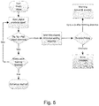
- Fig. 5 shows another operational principle of the signal processing routine (measuring engine) running in the processing unit 24 in phase III.
- the kinetic curve tracking is accomplished when the object (body portion) is not present in the monitored space.
- the presence of the body portion may be tolerated for a given elapsed time since the wetting detection.
- the user can be warned to remove his finger, such that the active test element 20 needs not to be discarded. Thereafter, an error message is displayed and the measurement is aborted.
- both the output signal of the proximity sensor 28 and the measuring values of the measuring unit 22 have to be supplied to the processing unit 24 for sequential or parallel processing. Furthermore, the processing unit 24 must be configured for evaluation of a duration of the proximity signal.
- a second confirmation of the blood application may be obtained by an evaluation of the proximity signal. This may be obtained comparing the digital proximity signal with empirical data for duration of object detection during wetting stored in a memory of the meter 12.
- Another option to employ the proximity sensor 28 would be to stop the tape transport while object recognition is positive to ensure a correct positioning of the test elements in the respective active position on the tip 16.
Landscapes
- Health & Medical Sciences (AREA)
- Life Sciences & Earth Sciences (AREA)
- Physics & Mathematics (AREA)
- Engineering & Computer Science (AREA)
- Biomedical Technology (AREA)
- General Health & Medical Sciences (AREA)
- Pathology (AREA)
- Molecular Biology (AREA)
- Biophysics (AREA)
- Veterinary Medicine (AREA)
- Animal Behavior & Ethology (AREA)
- Surgery (AREA)
- Medical Informatics (AREA)
- Heart & Thoracic Surgery (AREA)
- Public Health (AREA)
- Optics & Photonics (AREA)
- Spectroscopy & Molecular Physics (AREA)
- Hematology (AREA)
- Emergency Medicine (AREA)
- Chemical & Material Sciences (AREA)
- Biochemistry (AREA)
- Analytical Chemistry (AREA)
- Medicinal Chemistry (AREA)
- Food Science & Technology (AREA)
- Immunology (AREA)
- Urology & Nephrology (AREA)
- Human Computer Interaction (AREA)
- General Physics & Mathematics (AREA)
- Measurement Of The Respiration, Hearing Ability, Form, And Blood Characteristics Of Living Organisms (AREA)
- Investigating Or Analysing Biological Materials (AREA)
- Investigating Or Analysing Materials By The Use Of Chemical Reactions (AREA)
Abstract
The invention concerns a medical analyte testing system (10) and a method for its operation, the method comprising the steps of
- providing a disposable test element (20) at an application site in a handheld meter (12),
- applying body fluid from a user's body portion fluid on a reaction area of the test element (20),
- detecting by means of a detection unit (22) of the meter (12) a series of measuring values from the reaction area of the test element (20) and determining the analyte concentration from the series of measuring values,
- employing a proximity sensor (28) disposed within the meter (12) to sense the presence of the body portion (32) in a monitored space (36) in proximity to the reaction area of the test element (20), and
- controlling the processing of the measuring values depending on an output signal of the proximity sensor (28).
Description
- The invention concerns a method for determination of an analyte concentration in a body fluid. The invention further concerns an analyte concentration measurement device.
- In the field of blood glucose testing, it is known to provide a handheld glucose meter with a plurality of test elements for multiple successive tests. Specifically, test elements can be provided as chemistry fields on a test tape, which is loadable into the meter in the form of a replaceable tape cassette. Thus, the user has no need to take care of the disposal of each single test element. However, the instrument is generally used by patients outside a laboratory environment, and therefore the measurement may be susceptible to non-intended user handling. In extreme cases of user handling scenarios, significant measurement deviations may occur.
- From
WO 2015/173417 A1 it is known to provide a handheld test meter for use with test strips in the determination of glucose in a bodily fluid sample. For saving battery power, a proximity sensor module is configured to detect the presence of a user's body in order to switch the meter from standby to active mode. -
US 2015/0238131 A1 proposes to employ a proximity sensor to determine whether a body part of a user protrudes by a required amount within a housing aperture such that a lancing and blood collecting operation will be successful with a high degree of confidence. This document is not concerned with instrument handling during the ultimate measurement procedure, as the sample handling and processing is carried out in a fully automated way inside the housing. - On this basis the object of the invention is to further improve the known measuring methods and systems to enhance the accuracy and precision of the measurement results by controlled user handling during the data acquisition phase or detection phase.
- The combination of features stated in the independent claims is proposed to achieve this object. Advantageous embodiments and further developments of the invention are derived from the dependent claims.
- The invention is based on the idea of preventing measurements from being distorted by the presence of a body part. Thus, a method for determination of an analyte and specifically glucose in a body fluid is proposed according to the invention which comprises the steps of:
- providing a disposable test element at an application site in a handheld meter,
- providing a body fluid on a user's body portion and applying the body fluid on a reaction area of the test element,
- detecting, by means of a preferably photometric detection unit of the meter, a series of measuring values from the reaction area of the test element, and determining the analyte concentration at least in part from the series of measuring values,
- employing a proximity sensor disposed within the meter to sense the presence of the body portion in a monitored space in proximity to the reaction area of the test element, and
- controlling the processing of the measuring values depending on an output signal of the proximity sensor to avoid a bias in the determination of the analyte concentration caused by the presence of the body portion.
- Advantageously, a warning is provided to the user upon sensing the presence of the body portion in the monitored space. Such a warning may contribute to optimization of user handling.
- As a still stronger counteractive measure, it is also advantageous when the detection of measuring values is aborted and/or an error message is provided by the meter in case of observing prolonged presence of the body portion in the monitored space.
- Another improvement in this direction provides for measuring a time interval of presence of the body portion in the monitored space, and for aborting the detection of measuring values and/or providing an error message to the user after a predetermined length of the time interval.
- In order to account for specific sample application procedure, a wetting of the test element with body fluid is detected, and measuring of the time interval is started at the point in time when detecting the wetting.
- Preferably, the length of the time interval is in the range of 0,5 to 2 s.
- In order to account for intended use, the detection of measuring values is completed only if the body portion is not present in the monitored space.
- For a possible immediate intervention in the measuring process, it is also advantageous when the output signal of the proximity sensor is made available as an input for a processor unit of the meter during processing of the measuring values.
- It is further advantageous when the output signal of the proximity sensor is processed differently during at least two measuring phases. In this way, multiple benefits may be achieved from the implementation of the proximity sensor.
- For a dedicated discrimination of a problematic proximity it is advantageous to configure the proximity sensor such that the monitored space includes a cuboid in the size of at least 1 x 1 x 5 mm, preferably at least 3 x 3 x 10 mm, where the long side of the cuboid is perpendicular to a surface of the test element.
- Preferably, the output signal of the proximity sensor is provided as a digital value indicating solely the presence or absence of the body portion in the monitored space.
- According to a preferred implementation, the detection of measuring values comprises an initial measuring phase for measuring a blank value on the test element prior to body fluid application, an intermediate measuring phase for tracking a development of the measuring values, and a final measuring phase for determining an end value which is characteristic for a quantity of the analyte.
- A further improvement in this connection comprises transporting the test element on a transport tape over a deflection tip as a sample application site, and arranging the proximity sensor adjacent or in close proximity to the deflection tip.
- A still further improvement provides that the body fluid is applied on a freely accessible application side of the test element, and the measuring values are detected by scanning a back side of the test element opposite to the application side.
- Another aspect of the invention concerns an analyte concentration measurement device, in particular for blood glucose determination, comprising a handheld meter adapted to provide a disposable test element having a reaction area at an application site for applying body fluid from a user's body portion, a preferably photometric detection unit operable for detecting measuring values on or from the reaction area of the test element, and a proximity sensor disposed within the meter to sense the presence of the body portion in a monitored space in proximity to the reaction area of the test element, wherein a processor unit of the meter is configured for
- i) processing the measuring values for determining the analyte concentration, and
- ii) processing the measuring values depending on an output signal of the proximity sensor to avoid a bias in the determination of the analyte concentration caused by the presence of the body portion.
- In the following, the invention is further elucidated on the basis of an embodiment example shown schematically in the drawings, where
- Fig. 1
- shows a testing system including a handheld blood glucose meter configured for using a test tape cassette;
- Fig. 2
- is an extended section of the meter and a user's finger in proximity to a test element;
- Fig. 3
- is a time diagram of a measuring process including a proximity sensor signal;
- Fig. 4
- is a flow-chart of a signal processing routine during a blank value measurement phase; and
- Fig. 5
- is a flow-chart of a signal reading routine during a kinetic measurement phase.
- In the drawings, an exemplary embodiment of a medical analyte testing system for testing an analyte in a body fluid, specifically glucose in a blood sample is shown.
- As depicted in
Fig. 1 , thesystem 10 at least comprises a portableblood glucose meter 12 adapted to receive a disposable test tape cassette 14 (shown separately) which can be inserted into a compartment of themeter 12. Atip 16 of the insertedtape cassette 14 is accessible to the user upon opening atip cover 18. Thetape cassette 14 serves as a test magazine, as a plurality oftest elements 20 is provided on a spoolable transport tape for successive use on thetip 16. - The
handheld meter 12 is provided with aphotometric measuring unit 22 and a processor unit 24 (electronic micro-processor) for determining the concentration of the analyte from the measured values. The measuring result and other information can be displayed to the user on adisplay 24. Themeter 12 is further provided with aproximity sensor 28 to detect the presence of a body part during critical measuring phases, thus allowing to control user handling. Optionally, alancing aid 30 is attached to themeter 12 for simplifying lancing of a body part in order to sample blood. -
Fig. 2 depicts a handling situation in a partial cross section of thesystem 10 transverse to thetip 16 of the insertedtape cassette 14. For carrying out an analyte test, the user applies a drop of blood from hisfinger 32 to a top side of theactive test element 22 provided on thetip 16. Thetest element 22 is formed by a layered chemistry field on thetransport tape 34 which is responsive to the analyte by a color change. Then, the measuringunit 22 provided as a reflectometer allows a measurement of the analyte concentration by optical scanning the rear side oftest element 22 through thetransparent transport tape 34. - However, the measurement may be biased by the presence of the
finger 32 which appears to the reflectometer as a dark background behind the incompletely opaque chemistry field. This influence increases with decreasing distance to the critical test field area. In another adverse user handling scenario, continued finger pressure on thetest element 22 after sample application may lead to an unwanted modification of the layered test structure, specifically if a covering net provided for sample spreading is impressed into the chemistry field such that the optical measurement is impaired thereby. - Thus, the
proximity sensor 28 is configured to sense the presence of the body portion in a monitoredspace 36 in proximity to thetest element 22. Purposively, theproximity sensor 28 is placed laterally to thetape 34 adjacent to thetip 16. - The favored solid angle that will be surveilled by the
proximity sensor 28 should be as much as possible restricted. It should be ensured that the sensor does not detect objects outside a specified detection area, especially any support surface like e.g. a table. Ideally, the monitoredspace 36 should include a cuboid in the size of approximately 3 x 3 x 10 mm, where the long side of the cuboid is perpendicular to the top side of thetest element 20. Furthermore, the opticalanalyte measuring unit 22 should not be disturbed by theproximity sensor 28. - As a further design consideration, the
proximity sensor 28 should deliver a digital signal indicating solely the following cases: - (0) false- no object detected;
- (1) true - object within defined space detected.
- The
proximity sensor 28 may be formed as a kind of photometric sensor that can detect any kind of object. The working principle may be similar to that of the analyte measuring unit: Somehow modulated light is send out by a light source (LED). Any reflected light is collected by a photo detector. Depending on the amount of reflected light an analog signal is created. Via a set threshold the digital discrimination between absence and presence of an object is made. - For a proximity detection, there are also other sensor types conceivable, namely inductive, capacitive and ultrasonic sensors to detect the presence or absence of objects.
- As illustrated in
Fig. 3 , the measuring process may be divided in various measuring phases. The time diagram shows measuring values on a test element provided by using a main light source (symbol x) and at least one auxiliary light source (symbol o) of the measuringunit 22. In an initial measuring phase (phase I), a blank value is detected as a double-measurement on the yetunused test element 20 prior to sample application. Thereafter, the auxiliary light source is powered to enable wetting detection preferably at a different wavelength. In the following phase II, consecutive measuring values are registered with a given sampling rate of e.g. 5 Hz to enable recognition of the wetting of thetest element 22 due to sample application by the user. Such wetting leads to a signal decrease below a predetermined detection threshold. However, in the first seconds there is no reliable behavior of the reactive chemical layers of thetest element 22 due to swelling and diffusion processes. Therefore, a predetermined waiting time should be observed in phase III. - Then, the chemical reaction due to the presence of the analyte can be tracked in phase IV, where the reaction product leads to an increasing darkening and hence to less reflected light. The kinetic curve exhibits an asymptotic behavior, such that a given stop criterion is reached after a plurality of measurement readings. Finally, in phase V, an end value is recorded, eventually followed by a control measurement for sufficiency of sample application. As a measurement result, the analyte concentration value is determined from the ration of the end value to the blank value. All other measurements are only accessory to find this result.
-
Fig. 3 also shows a comparative measurement with intended use, i.e. absence of abody part 32 after the waiting time (upper curve associated with the dotted arrow shown in phase III), and with non-intended use, i.e. presence of the body part 32 (lower kinetic curve and continuous arrow in phase III). Associated therewith, the digital output signal of theproximity sensor 28 is shown below in dotted and continuous lines. It becomes readily apparent that the presence of the body part after sample application leads to a reduced background remission, which interferes the measuring result quite remarkably. - The information obtained by the
proximity sensor 28 in themeter 12 is processed differently during various measurement phases. If possible, appropriate feedback (visual, acoustic and/or haptic) is provided to the user, as explained in more detail below. -
Fig. 4 shows a flow-chart of a signal processing routine of theprocessing unit 24 in phase I when measuring the blank value. In case no object (finger) is detected by the proximity sensor, the blank value can be determined without bias of the measuringunit 22. In the other case, where the object is in proximity to thetest element 20, the blank value cannot be determined reliably and an error message is displayed as a feedback to the user. -
Fig. 5 shows another operational principle of the signal processing routine (measuring engine) running in theprocessing unit 24 in phase III. Here, the kinetic curve tracking is accomplished when the object (body portion) is not present in the monitored space. In this phase, the presence of the body portion may be tolerated for a given elapsed time since the wetting detection. Within this period, the user can be warned to remove his finger, such that theactive test element 20 needs not to be discarded. Thereafter, an error message is displayed and the measurement is aborted. - As apparent from the above description, both the output signal of the
proximity sensor 28 and the measuring values of the measuringunit 22 have to be supplied to theprocessing unit 24 for sequential or parallel processing. Furthermore, theprocessing unit 24 must be configured for evaluation of a duration of the proximity signal. - It is also conceivable to employ the
proximity sensor 28 for other surveillance tasks in the user handling of themeter 12. For example, in addition to the signal drop in phase II, a second confirmation of the blood application may be obtained by an evaluation of the proximity signal. This may be obtained comparing the digital proximity signal with empirical data for duration of object detection during wetting stored in a memory of themeter 12. Another option to employ theproximity sensor 28 would be to stop the tape transport while object recognition is positive to ensure a correct positioning of the test elements in the respective active position on thetip 16.
Claims (15)
- A method for determination of an analyte concentration in a body fluid comprising the steps ofa) providing a disposable test element (20) at an application site in a handheld meter (12),b) providing a body fluid on a user's body portion (32) and applying the body fluid on a reaction area of the test element (20),c) detecting, by means of a preferably photometric detection unit (22) of the meter (12), a series of measuring values from the reaction area of the test element (20), and determining the analyte concentration at least in part from the series of measuring values,d) employing a proximity sensor (28) disposed within the meter (12) to sense the presence of the body portion (32) in a monitored space (36) in proximity to the reaction area of the test element (20), ande) controlling the processing of the measuring values depending on an output signal of the proximity sensor (28) to avoid a bias in the determination of the analyte concentration caused by the presence of the body portion (32).
- The method of claim 1, wherein a warning is provided to the user upon sensing the presence of the body portion (32) in the monitored space (36).
- The method of claim 1 or 2, wherein the detection of measuring values is aborted and/or an error message is provided by the meter (12) when the presence of the body portion (32) in the monitored space (36) is observed.
- The method according to any of claims 1 to 3, further comprising measuring a time interval of presence of the body portion (32) in the monitored space (36), and aborting the detection of measuring values and/or providing an error message to the user after a predetermined length of the time interval.
- The method of claim 4, wherein a wetting of the test element (20) with body fluid is detected, and measuring of the time interval is started at the point in time when detecting the wetting.
- The method of claim 4 or 5, wherein the length of the time interval is in the range of 0,5 to 2 s.
- The method according to any of claims 1 to 6,
wherein the detection of measuring values is completed only if the body portion (32) is not present in the monitored space (36). - The method according to any of claims 1 to 7, wherein the output signal of the proximity sensor (28) is made available as an input for a processor unit (24) of the meter (12) during processing of the measuring values.
- The method according to any of claims 1 to 8, wherein the output signal of the proximity sensor (28) is processed differently during at least two different periods of time during the detection of the measuring values.
- The method according to any of claims 1 to 9, further comprising configuring the proximity sensor (28) such that the monitored space (36) includes a cuboid in the size of at least 1 x 1 x 5 mm, preferably at least 3 x 3 x 10 mm, where the long side of the cuboid is perpendicular to a surface of the test element (20).
- The method according to any of claims 1 to 10, wherein the output signal of the proximity sensor (28) is provided as a digital value indicating solely the presence or absence of the body portion (32) in the monitored space (36).
- The method according to any of claims 1 to 11, wherein the detection of measuring values comprises an initial measuring phase for measuring a blank value on the test element (20) prior to body fluid application, an intermediate measuring phase for tracking a development of the measuring values, and a final measuring phase for determining an end value which is characteristic for a quantity of the analyte.
- The method according to any of claims 1 to 12, further comprising transporting the test element (20) on a transport tape over a deflection tip (16) as a sample application site, and arranging the proximity sensor (28) adjacent or in close proximity to the deflection tip (16).
- The method according to any of claims 1 to 13, wherein the body fluid is applied on a freely accessible application side of the test element (20), and the measuring values are detected by scanning a back side of the test element (20) opposite to the application side.
- An analyte concentration measurement device, in particular for blood glucose determination, comprising a handheld meter (12) adapted to provide a disposable test element (20) having a reaction area at an application site for applying body fluid from a user's body portion (32), a preferably photometric detection unit (22) operable for detecting measuring values from the reaction area of the test element (20), and a proximity sensor (28) disposed within the meter (12) to sense the presence of the body portion (32) in a monitored space (36) in proximity to the reaction area of the test element (20), wherein a processor unit (24) of the meter (12) is configured fori) processing the measuring values for determining the analyte concentration, andii) processing the measuring values depending on an output signal of the proximity sensor (28) to avoid a bias in the determination of the analyte concentration caused by the presence of the body portion (32).
Priority Applications (9)
| Application Number | Priority Date | Filing Date | Title |
|---|---|---|---|
| EP16195524.0A EP3315069A1 (en) | 2016-10-25 | 2016-10-25 | Method for determination of an analyte concentration in a body fluid and analyte concentration measurement device |
| KR1020197011888A KR102252241B1 (en) | 2016-10-25 | 2017-10-24 | Method for determining analyte concentration in body fluid and device for measuring analyte concentration |
| JP2019522266A JP7141392B2 (en) | 2016-10-25 | 2017-10-24 | Method and device for determining analyte concentration in body fluids |
| EP17793905.5A EP3531913B1 (en) | 2016-10-25 | 2017-10-24 | Method for determination of an analyte concentration in a body fluid and analyte concentration measurement device |
| CN201780066149.1A CN109922730B (en) | 2016-10-25 | 2017-10-24 | Method for determining an analyte concentration in a body fluid and analyte concentration measuring device |
| PCT/EP2017/077137 WO2018077863A1 (en) | 2016-10-25 | 2017-10-24 | Method for determination of an analyte concentration in a body fluid and analyte concentration measurement device |
| CA3040979A CA3040979C (en) | 2016-10-25 | 2017-10-24 | Method for determination of an analyte concentration in a body fluid and analyte concentration measurement device |
| TW106136633A TWI766894B (en) | 2016-10-25 | 2017-10-25 | Method for determination of an analyte concentration in a body fluid and analyte concentration measurement device |
| US16/381,869 US11284817B2 (en) | 2016-10-25 | 2019-04-11 | Method for determination of an analyte concentration in a body fluid and analyte concentration measurement device |
Applications Claiming Priority (1)
| Application Number | Priority Date | Filing Date | Title |
|---|---|---|---|
| EP16195524.0A EP3315069A1 (en) | 2016-10-25 | 2016-10-25 | Method for determination of an analyte concentration in a body fluid and analyte concentration measurement device |
Publications (1)
| Publication Number | Publication Date |
|---|---|
| EP3315069A1 true EP3315069A1 (en) | 2018-05-02 |
Family
ID=57208144
Family Applications (2)
| Application Number | Title | Priority Date | Filing Date |
|---|---|---|---|
| EP16195524.0A Withdrawn EP3315069A1 (en) | 2016-10-25 | 2016-10-25 | Method for determination of an analyte concentration in a body fluid and analyte concentration measurement device |
| EP17793905.5A Active EP3531913B1 (en) | 2016-10-25 | 2017-10-24 | Method for determination of an analyte concentration in a body fluid and analyte concentration measurement device |
Family Applications After (1)
| Application Number | Title | Priority Date | Filing Date |
|---|---|---|---|
| EP17793905.5A Active EP3531913B1 (en) | 2016-10-25 | 2017-10-24 | Method for determination of an analyte concentration in a body fluid and analyte concentration measurement device |
Country Status (8)
| Country | Link |
|---|---|
| US (1) | US11284817B2 (en) |
| EP (2) | EP3315069A1 (en) |
| JP (1) | JP7141392B2 (en) |
| KR (1) | KR102252241B1 (en) |
| CN (1) | CN109922730B (en) |
| CA (1) | CA3040979C (en) |
| TW (1) | TWI766894B (en) |
| WO (1) | WO2018077863A1 (en) |
Families Citing this family (1)
| Publication number | Priority date | Publication date | Assignee | Title |
|---|---|---|---|---|
| US11717823B2 (en) | 2020-01-06 | 2023-08-08 | Bisu, Inc. | Microfluidic system, device and method |
Citations (4)
| Publication number | Priority date | Publication date | Assignee | Title |
|---|---|---|---|---|
| WO2002070734A1 (en) * | 2001-02-28 | 2002-09-12 | Home Diagnostics, Inc. | Method for determining concentration of an analyte in a test strip |
| US20100144048A1 (en) * | 2005-09-01 | 2010-06-10 | Wolfgang Petrich | Test system for analyzing body fluids |
| US20150238131A1 (en) | 2012-01-10 | 2015-08-27 | Sanofi-Aventis Deutschland Gmbh | Apparatus having a light emitting part |
| WO2015173417A1 (en) | 2014-05-16 | 2015-11-19 | Lifescan Scotland Limited | Hand-held test meter with body portion proximity sensor module |
Family Cites Families (22)
| Publication number | Priority date | Publication date | Assignee | Title |
|---|---|---|---|---|
| AU6186494A (en) * | 1993-05-07 | 1994-11-10 | Diasense, Inc. | Non-invasive determination of analyte concentration using non-continuous radiation |
| US5492118A (en) * | 1993-12-16 | 1996-02-20 | Board Of Trustees Of The University Of Illinois | Determining material concentrations in tissues |
| JPH09167952A (en) * | 1995-12-15 | 1997-06-24 | Keyence Corp | Photoelectric switch |
| US8465425B2 (en) * | 1998-04-30 | 2013-06-18 | Abbott Diabetes Care Inc. | Analyte monitoring device and methods of use |
| US20030212344A1 (en) * | 2002-05-09 | 2003-11-13 | Vadim Yuzhakov | Physiological sample collection devices and methods of using the same |
| DE10332283A1 (en) * | 2003-07-16 | 2005-02-03 | Roche Diagnostics Gmbh | System for taking body fluid |
| US7283245B2 (en) * | 2004-01-20 | 2007-10-16 | General Electric Company | Handheld device with a disposable element for chemical analysis of multiple analytes |
| US7348538B2 (en) * | 2006-02-03 | 2008-03-25 | Ge Infrastructure Sensing, Inc. | Methods and systems for detecting proximity of an object |
| JP5646337B2 (en) * | 2007-11-05 | 2014-12-24 | バイオセンサー,インコーポレーテッド | Optical sensor for determining the concentration of an analyte |
| EP2352031A4 (en) * | 2008-11-21 | 2014-12-31 | Terumo Corp | Device for measuring blood component |
| JP2012075750A (en) * | 2010-10-04 | 2012-04-19 | Olympus Corp | Biological component-measuring instrument |
| JP5724497B2 (en) * | 2011-03-18 | 2015-05-27 | セイコーエプソン株式会社 | Substance component detector |
| EP2508130A1 (en) * | 2011-04-05 | 2012-10-10 | Roche Diagnostics GmbH | Analysis system with measuring device and test element |
| CA3166020C (en) * | 2011-10-11 | 2024-01-09 | Senseonics, Incorporated | Electrodynamic field strength triggering system |
| WO2013104671A1 (en) | 2012-01-10 | 2013-07-18 | Sanofi-Aventis Deutschland Gmbh | A blood analysis meter |
| EP2893328B1 (en) * | 2012-09-05 | 2017-02-22 | Roche Diabetes Care GmbH | Method and device for determining sample application |
| JP2014075690A (en) * | 2012-10-04 | 2014-04-24 | Panasonic Corp | Portable terminal |
| WO2014086803A1 (en) * | 2012-12-04 | 2014-06-12 | Roche Diagnostics Gmbh | Method for hematocrit correction and glucose meter adapted therefor |
| CN105188561B (en) * | 2013-02-14 | 2019-04-05 | 保罗·威博 | The systems, devices and methods that biological tissue dissects |
| US20150176053A1 (en) | 2013-12-23 | 2015-06-25 | Cilag Gmbh International | Test strip insertion drive mechanism for analyte meter |
| JP2015198689A (en) | 2014-04-04 | 2015-11-12 | セイコーエプソン株式会社 | Biometric device and biometric method |
| KR102240512B1 (en) * | 2014-07-31 | 2021-04-16 | 삼성전자주식회사 | Glucose measuring device, glucose measuring method and electronic device having clucose measuring module |
-
2016
- 2016-10-25 EP EP16195524.0A patent/EP3315069A1/en not_active Withdrawn
-
2017
- 2017-10-24 WO PCT/EP2017/077137 patent/WO2018077863A1/en unknown
- 2017-10-24 JP JP2019522266A patent/JP7141392B2/en active Active
- 2017-10-24 KR KR1020197011888A patent/KR102252241B1/en active IP Right Grant
- 2017-10-24 EP EP17793905.5A patent/EP3531913B1/en active Active
- 2017-10-24 CA CA3040979A patent/CA3040979C/en active Active
- 2017-10-24 CN CN201780066149.1A patent/CN109922730B/en active Active
- 2017-10-25 TW TW106136633A patent/TWI766894B/en active
-
2019
- 2019-04-11 US US16/381,869 patent/US11284817B2/en active Active
Patent Citations (4)
| Publication number | Priority date | Publication date | Assignee | Title |
|---|---|---|---|---|
| WO2002070734A1 (en) * | 2001-02-28 | 2002-09-12 | Home Diagnostics, Inc. | Method for determining concentration of an analyte in a test strip |
| US20100144048A1 (en) * | 2005-09-01 | 2010-06-10 | Wolfgang Petrich | Test system for analyzing body fluids |
| US20150238131A1 (en) | 2012-01-10 | 2015-08-27 | Sanofi-Aventis Deutschland Gmbh | Apparatus having a light emitting part |
| WO2015173417A1 (en) | 2014-05-16 | 2015-11-19 | Lifescan Scotland Limited | Hand-held test meter with body portion proximity sensor module |
Also Published As
| Publication number | Publication date |
|---|---|
| CA3040979C (en) | 2021-10-05 |
| KR102252241B1 (en) | 2021-05-14 |
| US11284817B2 (en) | 2022-03-29 |
| US20190239781A1 (en) | 2019-08-08 |
| TWI766894B (en) | 2022-06-11 |
| JP7141392B2 (en) | 2022-09-22 |
| CN109922730B (en) | 2022-03-22 |
| EP3531913B1 (en) | 2020-11-18 |
| TW201821796A (en) | 2018-06-16 |
| EP3531913A1 (en) | 2019-09-04 |
| CA3040979A1 (en) | 2018-05-03 |
| KR20190053258A (en) | 2019-05-17 |
| WO2018077863A1 (en) | 2018-05-03 |
| JP2020500300A (en) | 2020-01-09 |
| CN109922730A (en) | 2019-06-21 |
Similar Documents
| Publication | Publication Date | Title |
|---|---|---|
| US8394637B2 (en) | Handheld analyzer for testing a sample | |
| EP0199484B1 (en) | Medical system | |
| US9366636B2 (en) | Analyte detection devices and methods with hematocrit/volume correction and feedback control | |
| US6906802B2 (en) | System for analyzing sample liquids containing a position control unit | |
| JP2017508586A (en) | Sample testing device with lancet advance tracking and color touch screen user interface | |
| US9869679B2 (en) | Methods and devices for photometrically determining sample application on test elements | |
| US11284817B2 (en) | Method for determination of an analyte concentration in a body fluid and analyte concentration measurement device | |
| CA2630719C (en) | Handheld analyzer for testing a sample | |
| JP2020500300A5 (en) | ||
| WO2019081632A1 (en) | Analyte measuring system and method |
Legal Events
| Date | Code | Title | Description |
|---|---|---|---|
| PUAI | Public reference made under article 153(3) epc to a published international application that has entered the european phase |
Free format text: ORIGINAL CODE: 0009012 |
|
| AK | Designated contracting states |
Kind code of ref document: A1 Designated state(s): AL AT BE BG CH CY CZ DE DK EE ES FI FR GB GR HR HU IE IS IT LI LT LU LV MC MK MT NL NO PL PT RO RS SE SI SK SM TR |
|
| AX | Request for extension of the european patent |
Extension state: BA ME |
|
| STAA | Information on the status of an ep patent application or granted ep patent |
Free format text: STATUS: THE APPLICATION IS DEEMED TO BE WITHDRAWN |
|
| 18D | Application deemed to be withdrawn |
Effective date: 20181103 |