JP5646337B2 - Optical sensor for determining the concentration of an analyte - Google Patents
Optical sensor for determining the concentration of an analyte Download PDFInfo
- Publication number
- JP5646337B2 JP5646337B2 JP2010533075A JP2010533075A JP5646337B2 JP 5646337 B2 JP5646337 B2 JP 5646337B2 JP 2010533075 A JP2010533075 A JP 2010533075A JP 2010533075 A JP2010533075 A JP 2010533075A JP 5646337 B2 JP5646337 B2 JP 5646337B2
- Authority
- JP
- Japan
- Prior art keywords
- radiation
- radiation beam
- analyte
- concentration
- emitting
- Prior art date
- Legal status (The legal status is an assumption and is not a legal conclusion. Google has not performed a legal analysis and makes no representation as to the accuracy of the status listed.)
- Expired - Fee Related
Links
Images


Classifications
-
- G—PHYSICS
- G01—MEASURING; TESTING
- G01N—INVESTIGATING OR ANALYSING MATERIALS BY DETERMINING THEIR CHEMICAL OR PHYSICAL PROPERTIES
- G01N21/00—Investigating or analysing materials by the use of optical means, i.e. using sub-millimetre waves, infrared, visible or ultraviolet light
- G01N21/17—Systems in which incident light is modified in accordance with the properties of the material investigated
- G01N21/47—Scattering, i.e. diffuse reflection
- G01N21/49—Scattering, i.e. diffuse reflection within a body or fluid
-
- A—HUMAN NECESSITIES
- A61—MEDICAL OR VETERINARY SCIENCE; HYGIENE
- A61B—DIAGNOSIS; SURGERY; IDENTIFICATION
- A61B5/00—Measuring for diagnostic purposes; Identification of persons
- A61B5/0059—Measuring for diagnostic purposes; Identification of persons using light, e.g. diagnosis by transillumination, diascopy, fluorescence
-
- A—HUMAN NECESSITIES
- A61—MEDICAL OR VETERINARY SCIENCE; HYGIENE
- A61B—DIAGNOSIS; SURGERY; IDENTIFICATION
- A61B5/00—Measuring for diagnostic purposes; Identification of persons
- A61B5/145—Measuring characteristics of blood in vivo, e.g. gas concentration, pH value; Measuring characteristics of body fluids or tissues, e.g. interstitial fluid, cerebral tissue
- A61B5/14532—Measuring characteristics of blood in vivo, e.g. gas concentration, pH value; Measuring characteristics of body fluids or tissues, e.g. interstitial fluid, cerebral tissue for measuring glucose, e.g. by tissue impedance measurement
-
- A—HUMAN NECESSITIES
- A61—MEDICAL OR VETERINARY SCIENCE; HYGIENE
- A61B—DIAGNOSIS; SURGERY; IDENTIFICATION
- A61B5/00—Measuring for diagnostic purposes; Identification of persons
- A61B5/145—Measuring characteristics of blood in vivo, e.g. gas concentration, pH value; Measuring characteristics of body fluids or tissues, e.g. interstitial fluid, cerebral tissue
- A61B5/1455—Measuring characteristics of blood in vivo, e.g. gas concentration, pH value; Measuring characteristics of body fluids or tissues, e.g. interstitial fluid, cerebral tissue using optical sensors, e.g. spectral photometrical oximeters
-
- G—PHYSICS
- G01—MEASURING; TESTING
- G01N—INVESTIGATING OR ANALYSING MATERIALS BY DETERMINING THEIR CHEMICAL OR PHYSICAL PROPERTIES
- G01N21/00—Investigating or analysing materials by the use of optical means, i.e. using sub-millimetre waves, infrared, visible or ultraviolet light
- G01N21/17—Systems in which incident light is modified in accordance with the properties of the material investigated
- G01N21/1717—Systems in which incident light is modified in accordance with the properties of the material investigated with a modulation of one or more physical properties of the sample during the optical investigation, e.g. electro-reflectance
-
- A—HUMAN NECESSITIES
- A61—MEDICAL OR VETERINARY SCIENCE; HYGIENE
- A61B—DIAGNOSIS; SURGERY; IDENTIFICATION
- A61B5/00—Measuring for diagnostic purposes; Identification of persons
- A61B5/72—Signal processing specially adapted for physiological signals or for diagnostic purposes
- A61B5/7235—Details of waveform analysis
- A61B5/7239—Details of waveform analysis using differentiation including higher order derivatives
-
- G—PHYSICS
- G01—MEASURING; TESTING
- G01N—INVESTIGATING OR ANALYSING MATERIALS BY DETERMINING THEIR CHEMICAL OR PHYSICAL PROPERTIES
- G01N21/00—Investigating or analysing materials by the use of optical means, i.e. using sub-millimetre waves, infrared, visible or ultraviolet light
- G01N21/17—Systems in which incident light is modified in accordance with the properties of the material investigated
- G01N21/1717—Systems in which incident light is modified in accordance with the properties of the material investigated with a modulation of one or more physical properties of the sample during the optical investigation, e.g. electro-reflectance
- G01N2021/1725—Modulation of properties by light, e.g. photoreflectance
Description
本発明は光学式材料解析及び光学式材料解析を用いて被分析物の濃度を決定することに関するものである。 The present invention relates to optical material analysis and determining the concentration of an analyte using optical material analysis.
糖尿病は、患者の循環系及び視覚の内臓器官だけでなく、患者のライフスタイルにも影響を及ぼす重大疾患である。現在、世界で2億人を越える糖尿病患者が報告されており、今後10年以内にその2倍になると予期されている。糖尿病治療の第1のステップは、血糖値を知ることにより、正しい食事及び医療の決定に役立てられるので、1日24時間ずっと患者の血糖値を測定することである。 Diabetes is a serious disease that affects not only the patient's circulatory and visual organs, but also the patient's lifestyle. Currently, more than 200 million diabetics are reported worldwide, and are expected to double in the next 10 years. The first step in treating diabetes is to measure the patient's blood glucose level for 24 hours a day because knowing the blood glucose level can help in making the right diet and medical decisions.
血糖値の濃度を測定する現在の方法は、典型的に、糖尿病患者に指に穴を開けさせて血を一滴採取させることが必要であり、その化学組成を血糖測定器により分析する。その手続きは全く無痛の訳ではなく、皮膚を傷めるので、糖尿病患者は、医者が処方すると同じ頻度で血糖値を調べることを嫌がることはよくあり、従って、十分に血糖値を測定することができない。 Current methods of measuring blood glucose levels typically require a diabetic to puncture a finger to collect a drop of blood, whose chemical composition is analyzed by a blood glucose meter. The procedure is not painless at all and hurts the skin, so diabetics often hate to look for blood sugar as often as doctors prescribe, and therefore can't measure blood sugar well enough .
現在、血糖値測定用の携帯機器の大多数は、指先に穴を開けて血液サンプルを採取することが必要である。次に、血液サンプルを、血糖値の濃度を示す試験紙上に置く。例としては、ライフスキャン会社(LifeScan Inc.)、ジョンソン・アンド・ジョンソン会社(Johnson & Johnson company)により販売されるワンタッチ(One Toouch)(登録商標)、ウルトラ(Ultra)(登録商標)の血糖測定器がある。これらの機器は、非常に小型でかなり正確であるが、指先に穴を開けて血液サンプルを採取することは、不都合であり痛みを伴うことがある。その上、不適切な穴開けと衛生状態は、指先感染のリスクをもたらす。 Currently, the vast majority of portable devices for measuring blood sugar levels require that a finger be drilled to collect a blood sample. The blood sample is then placed on a test strip showing the concentration of blood glucose. Examples include LifeScan Inc., One Toouch (R), Ultra (R) blood glucose measurement sold by LifeScan Inc., Johnson & Johnson company There is a vessel. Although these devices are very small and fairly accurate, it is inconvenient and painful to puncture a fingertip and collect a blood sample. Moreover, improper drilling and hygiene poses a risk of fingertip infection.
従来の指先穴開け方法の替わりとして、シグナス会社(Cygnus Inc.)は、グルコウォッチ(GlucoWatch)(登録商標)バイオグラフ・モニタを開発した。腕時計のように見えるこの機器は、小電流を用いて皮膚から間質体液を引き抜いて、グルコースを抽出して、イオン導入法センサとして作用する消耗経皮パッドに入れる。収集したグルコースは、イオン導入法センサ内の電気化学反応を誘発して電子を発生する。イオン導入法センサは、電子を測定して、電子放射レベルを体液内のグルコースの濃度と同等と見なす。この機器は、体液のグルコース値を、最長12時間まで20分ごとに調べる。12時間の作動の後に、そのバイオグラフ・モニタは、血糖値と比較するため、指プリック示度数を用いて較正しなければならない。この機器は、体液のグルコース値が血液より遅れを取るため、一部分において約10〜30%に決定される相対的測定誤差を有する。しかしながら、これらの機器の1つを購入さえできるためには、潜在的な買い手は、検診及び生化学検査を受けて合格しなければならない。その上、この機器は、また、敏感な皮膚を持つ幾人かの患者において、電流が導入される皮膚にひどい炎症を起こさせることが知られている。 As an alternative to conventional fingertip drilling methods, Cygnus Inc. has developed the GlucoWatch® Biograph Monitor. This device, which looks like a wrist watch, draws interstitial fluid from the skin using a small current, extracts glucose, and places it in a consumable transdermal pad that acts as an iontophoretic sensor. The collected glucose induces an electrochemical reaction in the iontophoretic sensor to generate electrons. An iontophoretic sensor measures electrons and considers the electron emission level to be equivalent to the concentration of glucose in the body fluid. This instrument checks the glucose level of body fluids every 20 minutes for up to 12 hours. After 12 hours of operation, the biograph monitor must be calibrated using finger prick readings for comparison with blood glucose levels. This instrument has a relative measurement error determined in part about 10-30% because the glucose value of the body fluid lags behind the blood. However, in order to be able to even purchase one of these devices, potential buyers must pass screening and biochemical tests. Moreover, this device is also known to cause severe irritation to the skin where current is introduced in some patients with sensitive skin.
グルコウォッチ(GlucoWatch)(登録商標)のような替わりの機器が成功しないため、他の非侵襲的測定の開発が始まった。これらの替わりの非侵襲的方法の多くは、光学的方法の使用を含む。これらの光学的方法のいくつかは、替わりの非侵襲的測定を提供する保証を示した。例えば、いくつかの光学的方法は、非電離放射線を用いて、消耗試薬の必要のない高速応答を与える示度数を得る。その上、より高機能化したレーザ及び光学検出器の可用性が増加するのにつれて、これらの光学検出器の使用に関連するコストが減少するので、光学的方法は非侵襲的測定のさらにもっと魅力的な替わりの形態になる可能性がある。 The development of other non-invasive measurements began because alternative devices such as GlucoWatch® were not successful. Many of these alternative non-invasive methods involve the use of optical methods. Some of these optical methods have shown assurance that they provide alternative non-invasive measurements. For example, some optical methods use non-ionizing radiation to obtain a reading that gives a fast response without the need for consumable reagents. Moreover, as the availability of more sophisticated lasers and optical detectors increases, the cost associated with the use of these optical detectors decreases, making optical methods even more attractive for non-invasive measurements. Possible alternative forms.
典型的な非侵襲的光学的方法は、指、前腕、舌、唇、大腿部又は腹部等のような人体のいくつかの選択部分を照射するために、光ビームを利用する。皮膚を伝播し、皮膚から反射し又は散乱する光は、照射された組織の組成についての情報を含む。それから、光は光学検出器により受けられて、分析されて、酸素又はヘモグロビンのような所定の被分析物の濃度が決定される。しかしながら、分析は本質的に複雑である、なぜならば、受信信号は非常に微弱であり、血液中の多くの被分析物によるだけでなく、ヒト皮膚の多様性と不均質性、常に変化する人間の生理及び皮膚の周りの外部環境さえも含む他の要因によってもまた、受信信号は容易に干渉される。吸光及び発光分光法、ラマン(Raman)分光法及び偏光と反射率の変化の測定のような従来の材料解析の光学的方法は、基準光ビームの顕著な散漫散乱のため、ヒト組織のような混濁媒質にとって、あまり適切ではない。 Typical non-invasive optical methods utilize a light beam to illuminate several selected parts of the human body such as fingers, forearms, tongues, lips, thighs or abdomen. Light that propagates through the skin and reflects or scatters from the skin contains information about the composition of the irradiated tissue. The light is then received by an optical detector and analyzed to determine the concentration of a predetermined analyte such as oxygen or hemoglobin. However, the analysis is inherently complex because the received signal is very weak, not only due to many analytes in the blood, but also the diversity and heterogeneity of human skin, constantly changing humans Other factors, including the physiology of the skin and even the external environment around the skin, can easily interfere with the received signal. Conventional material analysis optical methods, such as absorption and emission spectroscopy, Raman spectroscopy and measurement of changes in polarization and reflectivity, such as human tissue due to significant diffuse scattering of the reference light beam. Not very suitable for turbid media.
他の非侵襲的方法は、間質液内のグルコース量と毛細管血との間に存在する相関を利用するが、多大な時間を必要とする主要な不利点に悩まされる。さらに、その方法は、グルコース濃度の間接的測定のみ提供するが、これも、あいにく時間が遅延する。 Other non-invasive methods take advantage of the correlation that exists between the amount of glucose in the interstitial fluid and capillary blood, but suffer from major disadvantages that require significant time. Furthermore, the method provides only an indirect measurement of glucose concentration, which unfortunately is time delayed.
レーザ光音響分光法の技術が、その提供する高感度のため、痕跡検出で用いられている。レーザ光音響分光法では、高エネルギーレーザビームが、研究中の物質を照射するために、用いられる。そのビームは物質内に熱膨張を生じて、音響波を発生する。その波の特性は、その物質の光吸収係数によるだけでなく、熱膨張、比熱及び音速のような熱物理パラメータによってもまた、決定される。その上、音響波は、また、光学散乱により影響されるが、光学散乱は、圧電性結晶、マイクロホン、光ファイバーセンサ、レーザ干渉計又は回折センサのような高感度超音波検出器により測定できる、物質内の光の分布に影響を与える。 Laser photoacoustic spectroscopy techniques are used in trace detection because of the high sensitivity they provide. In laser photoacoustic spectroscopy, a high energy laser beam is used to irradiate the material under study. The beam undergoes thermal expansion in the material and generates an acoustic wave. The characteristics of the wave are determined not only by the light absorption coefficient of the material, but also by thermophysical parameters such as thermal expansion, specific heat and sound velocity. In addition, acoustic waves are also affected by optical scattering, which can be measured by sensitive ultrasonic detectors such as piezoelectric crystals, microphones, fiber optic sensors, laser interferometers or diffraction sensors. Affects the light distribution within.
例えば、光音響技術を利用した非侵襲性血糖測定に対する方法および装置は発明者チョー(Chou)の特許文献1および特許文献2に記載されている。照射すると、測定される試料の比較的薄い層内で、熱拡散長により特徴付けられる音響エネルギーが生成される。その音響出力は、一方の端部に測定セルが配置され、もう一方の端部に基準セルが配置された差分マイクロホンで検出される。検出された音響信号に基づいて、プロセッサが測定物質濃度を決定する。血流内のグルコースの濃度を決定するために、励起源を、好ましくは、約1520〜1850nmおよび約2050〜2340nmのスペクトル範囲であるグルコース吸収帯域に同調させて、強力な光音響出力を誘導する。これらの波長範囲では、水による吸収率は比較的低く、グルコースによる吸収率は比較的高い。 For example, a method and apparatus for non-invasive blood glucose measurement utilizing photoacoustic technology is described in Patent Document 1 and Patent Document 2 of the inventor Cho. Upon irradiation, acoustic energy characterized by thermal diffusion length is generated in a relatively thin layer of the sample being measured. The acoustic output is detected by a differential microphone in which a measurement cell is arranged at one end and a reference cell is arranged at the other end. Based on the detected acoustic signal, the processor determines the measured substance concentration. To determine the concentration of glucose in the bloodstream, the excitation source is preferably tuned to a glucose absorption band that is in the spectral range of about 1520-1850 nm and about 2050-2340 nm to induce a strong photoacoustic output. . In these wavelength ranges, water absorption is relatively low and glucose absorption is relatively high.
別の例として、発明者マッケンジー他(MacKenzie, et al)の特許文献3は、血糖値のような生物学的パラメータを測定するシステムを記載し、そのシステムは、光ガイドからのレーザパルスを指先のような軟部組織から成る身体の部分へ向けて、光音響相互作用を生成する。その結果生じる音響信号は、トランスデューサにより検出され、解析されて所望のパラメータを与える。 As another example, inventor MacKenzie, et al., US Pat. No. 5,697,086, describes a system for measuring biological parameters such as blood glucose levels, which system uses a fingertip to direct a laser pulse from a light guide. A photoacoustic interaction is generated toward a body part composed of soft tissues such as The resulting acoustic signal is detected by a transducer and analyzed to provide the desired parameter.
上記の光音響技術の全ては、少なくとも音響振動性能を考慮せずにエネルギーを媒質に適用することを教示しているため、比較的高いレーザ・パワーが必要であるという点で不利である。このため、これまでの技術ではエネルギーが不充分であり、得られる感度レベルが不適切である。 All of the above photoacoustic techniques are disadvantageous in that they require a relatively high laser power because they teach applying energy to a medium at least without considering acoustic vibration performance. For this reason, conventional techniques have insufficient energy and the resulting sensitivity level is inappropriate.
別の従来の光音響材料解析システムが発明者ゲバ他(Geca, et al)の特許文献4に記載されており、媒質内に含まれる対象成分濃度が、持続時間、周波数、数およびパワーが変更可能な等間隔の短パルスを含む光パルス列を用いる共鳴型光音響分光法により決定される。光の波長は、対象成分により光が吸収されるように選択する。照射すると、熱拡散長により特徴付けられる、媒質の比較的薄い層内における吸収光により、音響振動が生成される。パルス列内の光短パルスの繰り返し周波数が、薄膜として見なすことのできる媒質の薄い層の固有音響振動周波数と一致するように選択されて、音響振動の共鳴が得られる。音響共鳴振動の振幅および周波数の測定により、対象成分濃度を決定し、このシステムは血液成分の測定、特にグルコースの測定に適している。 Another conventional photoacoustic material analysis system is described in Patent Document 4 of the inventor Geca et al., And the concentration of the target component contained in the medium is changed in duration, frequency, number and power. It is determined by resonant photoacoustic spectroscopy using an optical pulse train containing possible equally spaced short pulses. The wavelength of light is selected so that light is absorbed by the target component. Upon irradiation, acoustic vibrations are generated by absorbed light in a relatively thin layer of the medium, characterized by a thermal diffusion length. The repetition frequency of the short optical pulses in the pulse train is selected to match the natural acoustic vibration frequency of a thin layer of medium that can be considered as a thin film, resulting in acoustic vibration resonance. By measuring the amplitude and frequency of the acoustic resonance vibration, the concentration of the target component is determined, and this system is suitable for measuring blood components, particularly glucose.
残念ながら、上記のシステムは、従来の光音響材料解析技術の大多数と同様に、不利である。本発明とは違って、異なる成分の吸収帯の重なり及びヒト皮膚のような媒質の弾性特性の不規則性を考慮せずに、エネルギーを媒質に適用することを教示している。このため、このような従来の技術では、得られる感度レベルが不適切であり、測定誤差が大きい。 Unfortunately, the above systems are disadvantageous, as are the majority of conventional photoacoustic material analysis techniques. Unlike the present invention, it teaches the application of energy to a medium without taking into account the overlap of absorption bands of different components and irregularities in the elastic properties of a medium such as human skin. For this reason, in such a conventional technique, the obtained sensitivity level is inappropriate and the measurement error is large.
本発明に一致して、第1の放射ビームを放射する働きをし、組織の実験領域を照射して第1の放射散乱を引き起こす第1の放射源と、複数の第2の放射ビームを放射する働きをし、周期的に前記実験領域を照射して周期的な複数の第2の放射散乱を引き起こす第2の放射源と、前記第1の放射散乱及び前記第2の放射散乱を検出して、検出された前記放射散乱を電気信号に変換するための少なくとも2つの検出器と、前記電気信号に基づいて被分析物の濃度を決定するためのプロセッサとを備える、組織内の被分析物の濃度を決定するための装置を提供する。 Consistent with the present invention, a first radiation source that serves to emit a first radiation beam, irradiates an experimental region of tissue to cause a first radiation scatter, and emits a plurality of second radiation beams. A second radiation source that periodically irradiates the experimental region to cause a plurality of second radiation scatters, and detects the first radiation scatter and the second radiation scatter. An analyte in the tissue comprising: at least two detectors for converting the detected radiation scatter into an electrical signal; and a processor for determining an analyte concentration based on the electrical signal. An apparatus for determining the concentration of is provided.
放射の最初の後方散乱を引き起こす第1の放射ビームを放射する第1の放射源と、放射の周期的後方散乱を引き起こし実験領域を周期的に照射する第2の放射ビームを放射する第2の放射源とを用いて、組織の前記実験領域を周期的に照射するステップと、前記最初の及び周期的後方散乱を検出するステップと、検出された前記後方散乱を電気信号に変換するステップと、前記電気信号に応じて被分析物の濃度を決定するステップと、前記濃度を表示するステップと、を備える、組織内の被分析物の濃度を決定するための方法を提供する。 A first radiation source that emits a first radiation beam that causes an initial backscattering of radiation; and a second radiation that causes a periodic backscattering of radiation and that periodically illuminates the experimental region. Periodically irradiating the experimental region of tissue with a radiation source, detecting the initial and periodic backscatters, and converting the detected backscatters into electrical signals; A method is provided for determining an analyte concentration in a tissue comprising determining an analyte concentration in response to the electrical signal and displaying the concentration.
さらに、本発明に一致して、被分析物を含む流体サンプルを得るステップと、流体ベースの装置を用いて前記被分析物の第1の濃度を決定するステップと、光学装置を用いて前記被分析物の第2の濃度を決定するステップと、前記第2の濃度が前記第1の濃度に等しいかどうかを決定し、前記第2の濃度が前記第1の濃度に等しくなければ、前記第2の濃度が前記第1の濃度に等しくなるように、前記光学装置のオフセット較正をするステップとを有する、被分析物の濃度を決定するための光学装置を較正するための方法を提供する。 Further in accordance with the present invention, obtaining a fluid sample containing the analyte, determining a first concentration of the analyte using a fluid-based device, and using an optical device for the analyte. Determining a second concentration of the analyte; determining whether the second concentration is equal to the first concentration; and if the second concentration is not equal to the first concentration, the second concentration. A method for calibrating the optical device for determining the concentration of the analyte, comprising: offset calibration of the optical device such that a concentration of 2 is equal to the first concentration.
また、本発明に一致して、被検者のグルコースの濃度を決定するための光学装置の中で用いられるプローブヘッドであって、第1の放射源、放射光源、第1の検出器及び第2の検出器と容易に伝達できる複数の光ファイバーの束と、第1の放射源及び第2の放射源へ電気信号を送信し、第1の検出器及び第2の検出器からの電気信号を送信するための入力/出力インターフェースとを備えるプローブヘッドを提供する。 Also consistent with the present invention, a probe head for use in an optical device for determining a subject's glucose concentration comprising a first radiation source, a radiation source, a first detector, and a first detector A plurality of optical fiber bundles that can be easily communicated with the two detectors, and an electrical signal to the first and second radiation sources, and the electrical signals from the first and second detectors. A probe head with an input / output interface for transmitting is provided.
本発明に一致して、光学的励起及び光学的検出を用いて、被検者内のグルコースの濃度を非侵襲的に決定するための本発明に一致する装置であって、励起ビームを放射し、前記被検者の表面を照射して、前記表面に物理的及び化学的変化の少なくとも1つを引き起こし、放射の最初の後方散乱を引き起こす第1の放射源と、プローブビームを周期的に放射し、前記被検者の表面を照射して、放射の周期的な後方散乱を引き起こす第2の放射源と、前記最初の後方散乱及び前記周期的な後方散乱を検出して、検出された前記後方散乱を前記物理的及び化学的変化の振幅、周波数又は減衰期間のうちの少なくとも1つの電気信号に変換するための少なくとも1つの検出器と、を備え、前記後方散乱は、前記物理的及び化学的変化により変調され、さらに、少なくとも前記物理的及び化学的変化の振幅、周波数又は減衰期間を時間にわたって微分することにより、グルコースの前記濃度を決定するためのプロセッサと、を備える装置を提供する。 Consistent with the present invention, an apparatus consistent with the present invention for non-invasively determining the concentration of glucose in a subject using optical excitation and optical detection, which emits an excitation beam. Periodically irradiating a probe beam with a first radiation source that irradiates the surface of the subject to cause at least one of physical and chemical changes to the surface and to cause an initial backscatter of radiation; And detecting a second radiation source that irradiates the surface of the subject to cause periodic backscattering of radiation, the first backscattering and the periodic backscattering, and the detected At least one detector for converting backscattering into an electrical signal of at least one of amplitude, frequency or decay period of the physical and chemical changes, the backscattering comprising the physical and chemical Modulated by And a processor for determining the concentration of glucose by differentiating at least the amplitude, frequency or decay period of the physical and chemical changes over time.
本発明に一致して、光学的励起及び光学的検出を用いて、被検者内のグルコースの濃度を非侵襲的に決定するための方法であって、前記被検者の表面を照射して、表面に物理的及び化学的変化の少なくとも1つを引き起こし、光の最初の後方散乱を引き起こすために、励起ビームを放射するステップと、前記被検者の表面を照射して、光の周期的な後方散乱を引き起こすために、プローブビームを周期的に放射するステップと、検出された前記後方散乱を少なくとも前記物理的及び化学的変化の振幅、周波数又は減衰期間の電気信号に変換するために、前記最初の後方散乱及び前記周期的な後方散乱を検出するステップと、を備え、前記後方散乱は前記物理的及び化学的変化により変調され、さらに、少なくとも前記物理的及び化学的変化の振幅、周波数又は減衰期間のうちの少なくとも1つを時間にわたって微分することにより、グルコースの前記濃度を決定するステップを備える方法を、さらに提供する。 Consistent with the present invention, a method for non-invasively determining glucose concentration in a subject using optical excitation and optical detection comprising irradiating the surface of the subject Emitting an excitation beam to cause at least one of physical and chemical changes to the surface and causing an initial backscatter of light; To periodically emit a probe beam and to convert the detected backscatter to an electrical signal of at least the amplitude, frequency or decay period of the physical and chemical changes, Detecting the initial backscattering and the periodic backscattering, the backscattering being modulated by the physical and chemical changes, and at least of the physical and chemical changes. Width, by differentiating over at least one time of the frequency or decay time, the method comprising the step of determining the concentration of glucose, further provided.
本発明に一致する追加の特徴及び利点は、以下の詳細な説明で一部は説明され、詳細な説明から一部は明らかであり、又は本発明の実施により知ることができる。本発明に一致する特徴及び利点は、添付の特許請求の範囲で特に指摘された要素及びその組み合わせにより、実現され達成されるであろう。 Additional features and advantages consistent with the present invention will be set forth in part in the following detailed description, and in part will be obvious from the detailed description, or may be learned by practice of the invention. Features and advantages consistent with the present invention will be realized and attained by means of the elements and combinations particularly pointed out in the appended claims.
前述の一般的な説明及び以下の詳細な説明は、共に、例示的かつ説明的のみであり、請求される発明を限定するものではない。 Both the foregoing general description and the following detailed description are exemplary and explanatory only and are not restrictive of the claimed invention.
添付図面は、本明細書の一部に組み込まれ、本明細書の一部を構成し、本発明のいくつかの実施形態を例示し、明細書と共に本発明の原理を説明するために役立つ。 The accompanying drawings are incorporated in and constitute a part of this specification, illustrate several embodiments of the invention, and serve to explain the principles of the invention together with the specification.
添付図面に関連して以下の詳細な説明から、本発明はもっと十分に理解され評価されるであろう。 The present invention will be understood and appreciated more fully from the following detailed description taken in conjunction with the accompanying drawings.
本発明の例示的な実施形態を添付図面を参照して詳細に説明する。可能な限り、同一又は類似の部分には、同一の参照番号を図面全体にわたって用いる。 Exemplary embodiments of the present invention will be described in detail with reference to the accompanying drawings. Wherever possible, the same reference numbers will be used throughout the drawings to refer to the same or like parts.
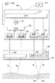
図1は、本発明に一致する、被分析物濃度を決定するための光学装置を例示する簡略ブロック図である。図1に示すように、光学装置は、光学部品筐体104に接続された電子機器筐体102を含む。電子機器筐体102は、導体、配線又は無線により光学部品筐体104に接続されるか、又は、電子機器筐体102及び光学部品筐体104は、それらの間の電気的接続をして単一の筐体に収容される。本発明の実施形態に一致して、光学部品筐体104は、さらに図3で例示するように、プローブを含む。
FIG. 1 is a simplified block diagram illustrating an optical apparatus for determining an analyte concentration consistent with the present invention. As shown in FIG. 1, the optical device includes an
光学部品筐体104内の光学部品は、表面106を放射ビームB1及びB2で照射して、第1の放射散乱D1及び第2の放射散乱D2を検出することを動作可能にできる。本発明に一致して、光学装置は、電源108に接続されて、電子機器筐体102、光学部品筐体104及びそれらの中にある部品に電力が与えられる。外部交流電源として例示されているけれども、電源108は電子機器筐体102か、又は、光学部品筐体104か、どちらかに含まれても良く、交流又は直流であっても良い。その上、電子機器筐体102と光学部品筐体104とが無線で接続されるならば、別個の追加の電源を光学部品筐体104に接続できる。光学装置は、表示用、モニタ用、トラッキング結果用及び光学装置の較正用の外部処理装置110に、さらに、接続できる。外部処理装置は、パソコン(PC)、携帯端末(PDA)、スマートフォン又は他のそのような装置を含んで良い。
Optics of the
本発明に一致して、電子機器筐体102は、被分析物濃度の決定を容易にするのに適している電子機器の配列を収容することができる。例えば、電子機器筐体102は、プロセッサ又はCPU112、第1の放射ドライバー114、第2の放射ドライバー116、第1のピーク検出器118、第2のピーク検出器120、マルチプレクサ(MUX)122及びアナログ・デジタル変換器(ADC)124を含むことができる。これらの機器の動作は、図2の議論に関連してさらに論じられよう。
Consistent with the present invention, the
同様に、光学部品筐体104は、被分析物濃度の決定をするのに用いる光学部品の配列を収容することができる。図1に示すように、光学部品筐体104は、表面106の実験領域130を第1の放射ビームB1及び第2の放射ビームB2で照射するための、第1の放射源126及び第2の放射源128を含むことができる。本発明に一致して、第1の放射ビームB1及び第2の放射ビームB2は、第1の放射ビームB1及び第2の放射ビームB2を生成できる単一の放射源127から放射できる。光学部品筐体104は、さらに第1の放射散乱D1及び第2の放射散乱D2を受けるための検出器を含むことができる。本発明に一致して、単一の検出器132は、第1の放射散乱D1、第2の放射散乱D2及び任意の他の放射散乱を受けるように構成することができる。さらに、本発明に一致して、図3に示すように、検出器132は、第1の放射散乱D1及び第2の放射散乱D2を別々に受けるための別々の散乱放射検出器を含むことができる。本発明の実施形態に一致して、検出器132は、ピン(PIN)フォトダイオード、アバランシェフォトダイオード、光電増倍管又はフォトレジスタ(Photoresistor)を含むフォトダイオードのような受光センサ(optical receiving sensor)を含むことができる。光増幅器(図示せず)は、第1の放射ビーム又は第2の放射ビームの出力を増幅するために、さらに光学部品筐体104に含めることができる。本発明に一致して、光増幅器は、光ファイバー増幅器で良い。光学部品筐体104は、また、第1の放射ビームB1及び第2の放射ビームB2の波長を変換するために、さらに光変換器(図示せず)を収容することができる。
Similarly, the
本発明に一致する実施形態において用いる第1の放射源及び第2の放射源は、被分析物濃度、必要な放射の周期性、サイズの制約又はコストを正確に決定するために、必要な放射の出力又は波長のような要因に依存して選択できる。例えば、第1の放射源126及び第2の放射源128は、パルスレーザーダイオード、ファイバー結合ダイオードレーザーアレイ、閃光電球又はパルス光ファイバーレーザーであっても良い。第1の放射源126及び第2の放射源又は単一の放射源127は、さらにこれらのタイプの放射源の組み合わせを含むことができる。例えば、一実施形態において、第1の放射源126又は第2の放射源128は、追加のダイオードレーザーにより励起されたエルビウム(Er)添加ガラスロッド又はスラブレーザを含むことができる。別の実施形態において、第1の放射源126又は第2の放射源128は、波長可変なCo:MgF2レーザを含むことができる。さらに別の実施形態において、第1の放射源126又は第2の放射源128は、ネオジム含有の光学媒質Q−スイッチレーザーを含むことができる。
The first and second radiation sources used in embodiments consistent with the present invention provide the necessary radiation to accurately determine the analyte concentration, the periodicity of radiation required, size constraints or cost. Depending on factors such as power or wavelength. For example, the
本発明に一致して、再使用の放射される放射源の特性は、調べられる特定の被分析物に依存するであろう。すなわち、例えば出力、放射のタイプ、波長及び周期性は、第1の放射源126及び第2の放射源128から放射される第1の放射ビームB1及び第2の放射ビームB2の特性に影響するだろうし、これらの特性は特定の被分析物に各々異なって影響するだろうし、従って、被分析物濃度を決定する光学装置の機能を最大にするために、これらの特性を調整することが重要である。異なる材料は、異なる反射率、透過率及び吸収特性を示す。特定の媒質内の被分析物濃度を決定するために、光学測定を行なう際、被分析物及び媒質の特性を考慮しなければならない。被分析物により吸収され散乱される放射量は、放射ビームの出力及び波長に依存する。従って、調査対象であり、周囲の媒質から区別される被分析物に帰属可能で、測定可能な吸収量及び散乱量を生成するのに十分な特定の出力及び波長で、放射ビームを放射することが望ましい。例えば第1の放射ビームB1及び第2の放射ビームB2は、所定の波長及び所定の出力を有して、放射されるであろう。本発明の実施形態に一致して、所定の波長及び出力は、調査対象の被分析物に応じて同一のもの又は異なるものにできる。
Consistent with the present invention, the characteristics of the reused emitted radiation source will depend on the particular analyte being examined. That is, for example, power, radiation type, wavelength, and periodicity depend on characteristics of the first radiation beam B 1 and the second radiation beam B 2 radiated from the
本発明に一致する特定の実施形態において、第1の放射ビームB1及び第2の放射ビームB2は、特定の媒質内で調査される被分析物の特有の吸収帯から選択される所定の波長を有して放射される。別の実施形態において、第1の放射ビームB1及び第2の放射ビームB2は、調査される被分析物の吸収帯のピーク波長に対応する波長で放射される。第1の放射ビームB1及び第2の放射ビームB2が異なる波長で放射される実施形態において、一方の放射ビームB1又は放射ビームB2は被分析物の吸収帯のピーク波長よりも大きい波長を有し、他方の放射ビームB1又は放射ビームB2は被分析物の吸収帯のピーク波長よりも小さい波長を有する。さらに詳細に以下で説明するように、特定の実施形態において、本発明に一致して、第1の放射ビームB1は、約1〜10Wの電力及び約1550nmの波長で放射され、第2の放射ビームB2は、約0.1〜1Wの電力及び約1550〜1690nmの波長で放射される。 In certain embodiments consistent with the present invention, the first radiation beam B 1 and the second radiation beam B 2 is the predetermined selected from the absorption band characteristic of the analyte being examined in a particular medium Radiated with a wavelength. In another embodiment, the first radiation beam B 1 and the second radiation beam B 2 is emitted at a wavelength corresponding to the peak wavelength of the absorption band of the analyte to be investigated. In embodiments where the first radiation beam B 1 and the second radiation beam B 2 is emitted at a different wavelength, greater than the peak wavelength of the absorption band of one of the radiation beams B 1 or the radiation beam B 2 is the analyte It has a wavelength, the other of the radiation beams B 1 or the radiation beam B 2 has a smaller wavelength than the peak wavelength of the absorption band of the analyte. As described in more detail below, in certain embodiments, consistent with the present invention, the first radiation beam B 1 is emitted at a power of about 1-10 W and a wavelength of about 1550 nm, the radiation beam B 2 is emitted at a wavelength of power of about 0.1~1W and about 1550~1690Nm.
すでに述べたように、第1の放射源126及び第2の放射源128は、パルス放射源を含むことができる。パルス放射源を用いる実施形態では、第1の放射ビームB1及び第2の放射ビームB2も、また、パルス状である。例えばパルス源を用いる際、第1の放射ビームB1及び第2の放射ビームB2は、パルス間に所定の遅れを有するモノラルパルスとして放射される。第1の放射ビームB1及び第2の放射ビームB2は、また、それらの間に等しい間隔及び可変繰り返し率を有する準連続(QCW)光の短パルスとして放射される。さらに、第1の放射ビームB1及び第2の放射ビームB2は、パルス列として、かつ、可変周波数、可変パルス電力、可変パルス持続時間及び可変パルス数を有するものとして放射される。以下に記載するように、特定の実施形態において、第2の放射ビームB2は、周期的に実験領域130を照射するために、等しい間隔を有する短パルスとして放射される。
As already mentioned, the
本発明に一致して、被分析物濃度を決定するための方法を例示するフローチャートである図2を参照する。本発明に一致する実施形態において、図2に例示する方法は、図1に例示する光学装置を用いて実施される。このような実施形態を例示するために、図2のステップを図1の動作に関連して説明する。 Consistent with the present invention, reference is made to FIG. 2, which is a flowchart illustrating a method for determining an analyte concentration. In an embodiment consistent with the present invention, the method illustrated in FIG. 2 is performed using the optical device illustrated in FIG. In order to illustrate such an embodiment, the steps of FIG. 2 will be described in connection with the operation of FIG.
光学部品筐体104であるプローブは、最初に、表面106の実験領域130に接触するように置かれる(S201)。本発明に一致して、プローブは、実験領域130に接触しても良いし、又は実験領域130の近くにあっても良い。さらに本発明に一致して、実験領域130は表面106にあっても良いし、又は表面106の下にあっても良い。実験領域130は、励起パルスである第1の放射源126から放射される第1の放射ビームB1で照射される(S202)。続いて、実験領域130は、プローブパルスである第2の放射源128から放射される第2の放射ビームB2で照射される(S203)。
The probe that is the
本発明に一致して、第2の放射源128は、各ビームがそれらの間の所定の周期で放射される複数の第2の放射ビームB2を放射できる。第1の放射ビームB1及び第2の放射ビームB2は実験領域130を照射するだろうし、所定の量の放射は第1の放射散乱D1及び第2の放射散乱D2として例示されるように、表面106の反射率に依存して実験領域130から散乱して戻される。その上、第1の放射ビームB1及び第2の放射ビームB2は、さらに表面106に周期的又は非周期的過渡プロセスを引き起こして、この過渡プロセスが少なくとも部分的に第1の放射散乱D1及び第2の放射散乱D2を調整する。
Consistent with the present invention, the
第1の放射散乱D1及び第2の放射散乱D2は、それから検出器132により検出される(S204)。検出器132は、検出した第1の放射散乱D1及び第2の放射散乱D2を処理用の電気信号に変換する。本発明に一致して、電気信号は、表面106に生じる任意の過渡プロセスの振幅、周波数又は減衰期間の内の少なくとも1つを表す。電気信号は、それから、第1のピーク検出器118及び第2のピーク検出器120からマルチプレクサ122ヘ送信される。マルチプレクサ122は、第1のピーク検出器118及び第2のピーク検出器120からの電気信号を結合して、単一の結合電気信号をアナログ・デジタル変換器124へ出力する。アナログ・デジタル変換器124は、入力したアナログ電気信号をデジタル電気信号へ変換して、デジタル電気信号をプロセッサ112へ出力する。
First radiation scattering D 1 and the second radiation scattered D 2 is then detected by the detector 132 (S204).
プロセッサ112は、デジタル電気信号を受信して、内部メモリ(図示せず)に保存される命令を実行し、デジタル電気信号を用いて計算を実施する。例えば、プロセッサ112は、第1の放射散乱D1及び第2の放射散乱D2の強度の変化を計算し(S205)、その強度の変化は、第2の放射ビームB2の放射の繰り返しにより、及び、放射された第1の放射ビームB1又は第2の放射ビームB2の結果として表面106に生じる、その後の任意の過渡プロセスにより引き起こされる。計算された強度の変化から、プロセッサ112は、それから、命令を実行し、実験領域130にある被分析物の濃度を計算するアルゴリズムを実施する(S206)。本発明に一致して、計算も、例えばPC110内のプロセッサのような外部プロセッサにより行われる。計算された濃度は、それから、ユーザが見るために表示される(S207)。本発明に一致して、計算された濃度は、電子機器筐体102に取り付けられたディスプレイ上に又はコンピュータ上に表示される。その上、計算された濃度は、また、トレンド分析及び長時間分析のため、コンピュータ110の中に表にされる(be tabulated)。
The
本発明に一致して、画像解析技術は、本明細書に記載された光学装置に関連して用いられる。特に、画像解析技術は、第1の放射ビームB1及び第2の放射ビームB2が実験領域130に変化せずに常に入射することを確保するために用いられる。画像解析技術は、光学装置に取り付けられた及び/又は埋め込まれたビデオハードウェア及びソフトウェアを含み、そのビデオハードウェア及びソフトウェアは、第1の放射ビームB1及び第2の放射ビームB2が実験領域に常に入射するように、ユーザが光学装置を正確に位置付けることを可能にする。本発明に一致して、リアルタイムのビデオ送りがユーザの光学装置の表面106上の位置付けを示すことができるように、携帯用ビデオカメラをインストールできる。標識を実験領域130に置くことができ、その結果、ユーザは、ビデオ送りを用いて、実験領域130への入射を確保するために、光学装置を実験領域130に確実に調整することができる。
Consistent with the present invention, image analysis techniques are used in connection with the optical devices described herein. In particular, the image analysis technique is used to ensure that the first radiation beam B 1 and the second radiation beam B 2 are always incident on the
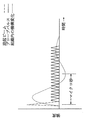
図3は、図1の光学部品筐体の実施形態を例示する。本実施形態において、図1の光学部品筐体104は、プローブ又はプローブヘッド304に形成される。プローブヘッド304は、第1の放射体126及び第2の放射体128を含むことができる少なくとも1つの放射体並びに検出器132内で表面106に関して異なる間隔を有する第1の散乱放射検出器332及び第2の散乱放射検出器334を含むことができる少なくとも1つの検出器132を含む。プローブヘッド304は、また、第1の放射体及び第2の放射体から放射された放射ビームを実験領域130に合焦するための第1のレンズ306を含むことができる。プローブヘッド304は、また、表面106からの散乱放射を第2の散乱放射検出器334及び第1の散乱放射検出器332にそれぞれ集める第2のレンズ308及び第3のレンズ310を含むことができる。図3では示していないけれども、プローブヘッド304は、さらに、図1で示す電子機器筐体102に収容されたもののような他の電子処理機器に接続できる。
FIG. 3 illustrates an embodiment of the optical component housing of FIG. In the present embodiment, the
図3で示すように、本発明に一致する実施形態において、検出器132を表面106から所定の距離に設ける。本発明に一致して、第2の散乱放射検出器334は、プローブヘッド304内で、第1の散乱放射検出器332と表面106との間の距離よりも大きい表面106からの距離で、設けられる。第2の散乱放射検出器334を表面106からより大きい距離に設けることにより、光学装置は、差分解析を行うための追加のデータ点を生成でき、濃度の示度数の正確さを増加する。例えば、第1の放射ビームB1及び第2の放射ビームB2により励起される所定のシステムに対して、第2の散乱放射検出器334で検出された散乱の振幅は、第1の散乱放射検出器332で検出された散乱の振幅よりも小さくて、2つの散乱放射検出器で検出された散乱間の相対的振幅を計算するために、用いることができる。この相対的振幅は、位置決め、圧力又は放射源の不安定性により引き起こされる誤差を相殺するために用いることができる。検出された散乱の振幅が検出されたパラメータとして説明されてきたけれども、本発明に一致して、そのパラメータは散乱の周波数又は減衰期間に関連することができる。
As shown in FIG. 3, in an embodiment consistent with the present invention, a
本発明の別の実施形態において、プローブヘッド304は、また、接触センサ、近接センサ又は圧力センサである、ゲートセンサ302を含むことができる。接触センサをゲートセンサ302として用いる実施形態において、接触センサは、実験が始められる前にプローブヘッド304と表面106との接触を検出しなければならず、従って、ゲートとして作用する。近接センサをゲートセンサとして用いる実施形態において、近接センサは、表面106がプローブヘッド304に合理的に近接していることを検出しなければならない。すなわち、近接センサを用いる実施形態において、近接センサは、実験が始められる前にプローブヘッド304と表面106との間に所定の距離が存在することを決定する。
In another embodiment of the invention, the
圧力センサを用いる実施形態において、圧力センサ302は、実験が始める前に所定の圧力を検出しなければならない。図1及び図2を参照して上記に論じたように、散乱ビームD1及びD2の強度の検出した変化は、第1の放射ビームB1及び第2の放射ビームB2により引き起こされる過渡プロセスにより影響される。プローブヘッド304を表面106に接触して置く際、追加の過渡プロセスが表面106に導入されて、さらに散乱ビームD1及びD2の強度の変化に影響を与え、従って、また、被分析物の計算された濃度に影響を与える。しかしながら、プローブにより表面106に加えられるある圧力は、被分析物の濃度を計算する際、既知の圧力及びその影響を考慮に入れることができ、修正することができるように、オフセットとして用いることができる。圧力センサ302によりプローブヘッド304と表面106との間で検知される圧力は、第1の放射体126が第1の放射ビームB1を放射する前の所定の圧力に等しくなければならない。圧力センサ302は、光ファイバー圧力プローブを備えることができる。
In embodiments using a pressure sensor, the
本発明の実施形態に一致して、プローブヘッド304は光ファイバープローブを備える。本実施形態で、プローブヘッド304は多くの光ファイバーを備えており、光ファイバーは、少なくとも1つの放射源及び少なくとも1つの検出器と光通信を行う。例えば、光ファイバーは、第1の放射源126、第2の放射源128、第1の検出器332及び第2の検出器334と光通信を行う。光ファイバーの束は、表面106に出入りする放射を送るための導管又は導波管として作動する。このような実施形態に一致して、多くの光ファイバーを図7に示すように配置することができる。光ファイバーの使用により小型、軽量かつ容易に表面106に接触して置くことができるプローブヘッド304の提供を可能にする。
Consistent with embodiments of the present invention,
図7は本発明に一致する光ファイバーの配置の例を示す。図7(a)は光ファイバーの配置を例示し、その光ファイバーは、放射源126及び/又は128からの放射を送るための3つの光ファイバー726を含み、かつ、表面106からの散乱放射を放射検出器132を含むことができる放射検出器へ送るための複数の収集光ファイバー732を含む。図7(b)は光ファイバーの配置を例示し、その光ファイバーは、放射源126及び/又は128からの放射を送るための2つの光ファイバー726を含み、かつ、表面106からの散乱放射を放射検出器132を含むことができる放射検出器へ送るための複数の収集光ファイバー752を含む。図7(c)は光ファイバーの配置を例示し、その光ファイバーは、放射源126及び/又は128からの放射を送るための2つの光ファイバー726を含み、かつ、表面106からの散乱放射を放射検出器132又は332を含むことができる放射検出器へ送るための近くの複数の収集光ファイバー732を含み、かつ、表面106からの散乱放射を図3に示す放射検出器334へ送るための遠くの複数の収集光ファイバー734を含む。
FIG. 7 shows an example of an optical fiber arrangement consistent with the present invention. FIG. 7 (a) illustrates an arrangement of optical fibers, which include three
本明細書に記載された光学装置は、ヒト組織内のグルコース濃度の検出のためのある実施形態に用いることができる。本発明に一致して、ヒト組織内のグルコースの検出のための実施形態は、励起パルスとして短く高出力の放射ビームB1を、本実施形態では組織である表面106の実験領域130へ放射する。放射の一部は表面106により吸収されて、表面106に過渡プロセスを生成し、この過渡プロセスは、表面106の光学的、機械的及び他の物理的特性並びに化学的特性を変化させる。これらの特性の変化は、続いて、表面106の光音響振動と同様に、散乱放射D1及びD2の振幅、周波数及び減衰期間を変化させる。
The optical devices described herein can be used in certain embodiments for the detection of glucose concentration in human tissue. Consistent with the present invention, an embodiment for the detection of glucose in human tissue, the radiation beams B 1 high-output short as the excitation pulse, in the present embodiment radiates the
放射ビームB1の最初の放射後、第2の放射源128は、プローブパルスとして作用する第2の放射ビームB2を周期的に放射する。これらのプローブパルスは、表面106に最小の過渡プロセスのみを誘導するように、典型的に第1の放射ビームB1より低い出力である。プローブパルスは、表面106が時間とともに緩和するので、検出器132により検出することのできる追加の放射散乱D1及びD2を生成するのに役立つ。表面106は、最初の高出力放射ビームB1から緩和するので、検出器132は検出示度数を得ることができて、その検出示度数を処理することができて、最初の励起パルス及び続いてプローブパルスから散乱光の振幅を決定し、散乱光の振幅の時間にわたる変化を決定し、導入された過渡プロセスの結果として生じる変調の振幅及び周波数を決定し、表面106の減衰定数を決定し、プローブパルスからの散乱光の振幅変調の位相遅れを決定し、この位相遅れにより表面106の音響波の伝播速度の計算を可能にする。これらの処理値から、表面106に存在するグルコースの濃度を決定できる。本発明に一致する光学装置を用いる特別の実施例を以下に詳細に論じる。
After the first radiation of the radiation beam B 1, the
本発明に一致する実施形態において、例えば、図1に関する上記のような光学装置は、図1の表面106がヒト組織であるように、被験者のグルコース濃度の決定のために用いられる。図4は、本実施形態に一致する光学装置により放射される、異なるタイプの放射の強度及び持続時間を例示するグラフである。本実施形態に対して、第1の放射源126及び第2の放射源128は、約1590nmのピークを有するグルコース吸収帯に対応するように選択される。本実施形態で、光学装置には、第1の放射源126が、1550nmの波長、1.0〜10.0Wの電力、100nsのパルス幅の励起ビームB1を放射するレーザであるように設ける。第2の放射源128は、1550nmの波長、1.0〜10.0Wの電力、80nsのパルス幅の複数の周期的なプローブパルスB2を放射するように設けたレーザである。
In an embodiment consistent with the present invention, for example, an optical device as described above with respect to FIG. 1 is used for determination of a subject's glucose concentration, such that
動作中、光音響原理に従って、励起ビームB1は、組織106内に機構変化及び高速減衰振動を生成する。励起ビームB1は、また、最初の光の散乱D1又はD2を生成する。励起ビームB1の放射後、プローブパルスB2が周期的に放射されて、追加の光の散乱D1又はD2を生成する。光の散乱D1及びD2は、検出器132により検出されて、光の散乱D1及びD2の振幅の強度を表わす電気信号に変換されて、処理のため電子機器筐体102へ送られる。
In operation, according to the photoacoustic principle, the excitation beam B 1 generates a mechanism change and fast damped oscillation in the
組織106内の機構変化及び高速減衰振動により、追加の光の散乱D1又はD2の振幅は時間とともに変化する。CPU112は、振幅の変化を表わす電気信号を処理して、その結果をPC110へ送る。PC110は、専用のアルゴリズムを用いて、電気信号を保存し、組織106内のグルコース濃度を計算する。
Due to mechanical changes in
本発明に一致する別の実施形態において、例えば、図3に関する上記のような光学装置は、図3の表面106がヒト組織であるように、被験者のグルコース濃度の決定のために用いられる。図5は、本実施形態に一致する光学装置により放射される、異なるタイプの放射の強度及び持続時間を例示するグラフである。本実施形態に対して、第1の放射源126及び第2の放射源128は、約1590nmのピークを有するグルコース吸収帯に対応するように選択される。本実施形態で、光学装置には、第1の放射源126が、1550nmの波長、5Wの電力、100nsのパルス幅の励起ビームB1を放射するレーザであるように設ける。第2の放射源128は、1610〜1690nmの波長、0.25〜0.5Wの電力、80nsのパルス幅の複数の周期的なプローブパルスB2を放射するように設けたレーザである。
In another embodiment consistent with the present invention, for example, an optical device as described above with respect to FIG. 3 is used for determination of a subject's glucose concentration such that
あるいは、本発明に一致して、励起ビームB1は、1550nmの波長及び10Wの電力で放射することができ、周期的なプローブパルスB2は、1550nmの波長及び約0.25〜0.5Wの電力で、励起ビームB1と同じ放射源から放射することができ、周期的なプローブパルスB2について各パルス間に約25マイクロ秒の遅れがあるように、放射される。 Alternatively, consistent with the present invention, the excitation beam B 1 can be emitted at a wavelength of 1550 nm and a power of 10 W, and the periodic probe pulse B 2 can be emitted at a wavelength of 1550 nm and about 0.25 to 0.5 W. in power, excitation beams B 1 and can be emitted from the same radiation source, such that there is a delay of approximately 25 microseconds between each pulse for periodic probe pulses B 2, is emitted.
動作中、プローブヘッド304は組織106に接触して置かれる。本例では圧力センサを備えるゲートセンサ302は、プローブヘッド304と組織106との間の圧力を測定する。圧力センサ302が、プローブヘッド304と組織106との間の圧力が許容できる値であることを決定すると、第1の放射源が励起ビームを放射する。光音響原理に従って、励起ビームは、組織106内に機構変化及び高速減衰振動を生成し、また、最初の光の散乱を生成する。励起ビームの放射後、プローブパルスが第2の放射源128により周期的に放射されて、追加の光の散乱を生成する。光の散乱は、第1の検出器332及び第2の検出器334により検出されて、光の散乱の振幅の強度を表わす電気信号に変換されて、処理のため電子機器筐体102(図1に示す)へ送られる。
In operation, the
組織106内の機構変化及び高速減衰振動により、追加の光の散乱の振幅は時間とともに変調する。CPU102(図1に示す)は、振幅の変化を表わす電気信号を処理して、光の散乱の振幅を時間とともに互いに比較するためのアルゴリズムを実行して、振幅においてだけでなく、周波数、減衰期間及び音響振動の拡散速度における微分変化も探す。これらの微分変化は、内部メモリ(図示せず)に保存されて、それから、組織106内のグルコース濃度を計算するためのアルゴリズムで使用される。
Due to the mechanism changes and fast damped oscillations in the
本発明に一致して、必ずしも必要ではないけれども、被分析物濃度の最適な決定を提供するために、図1又は図3で例示する光学装置を較正することができる。図6は、本発明に一致する光学装置を較正するための方法を例示するフローチャートである。上記のように、実験される被分析物がグルコースであれば、得られる濃度が正確であり、かつ、一般に認められたグルコース濃度の実験手段に適合することが、ユーザの健康にとって重要である。従って、較正プロセスの実行において、標準血液テストの結果が光学装置の結果と比較されて、光学装置は、標準血液テストに適合するために、オフセット較正がされる。この較正プロセスはグルコースの実験に関してまとめられているけれども、以下に詳細に説明する較正プロセスは、また、グルコース以外の被分析物濃度を決定するために、本発明に一致する光学装置を用いる際に用いることができる。 Consistent with the present invention, the optical device illustrated in FIG. 1 or FIG. 3 can be calibrated to provide an optimal determination of analyte concentration, although this is not necessary. FIG. 6 is a flowchart illustrating a method for calibrating an optical device consistent with the present invention. As noted above, if the analyte being tested is glucose, it is important for the user's health that the concentration obtained is accurate and compatible with generally accepted experimental means of glucose concentration. Thus, in performing the calibration process, the results of the standard blood test are compared with the results of the optical device, and the optical device is offset calibrated to meet the standard blood test. Although this calibration process has been summarized for glucose experiments, the calibration process described in detail below is also useful when using optical devices consistent with the present invention to determine analyte concentrations other than glucose. Can be used.
最初に流体サンプルが得られて(S401)、流体濃度決定手段を用いて被分析物の第1の濃度が決定される(S402)。この第1の濃度は記録されて、それから本発明に一致する光学装置は、濃度測定のために用いられる(S403)。光学装置は、図2に例示されるような方法を実行して、被分析物の第2の濃度を決定する(S404)。第1の濃度及び第2の濃度はお互いに比較されて、所定の正確度の範囲内で一致するかどうかを決定する(S405)。第1の濃度及び第2の濃度が一致すれば、さらに較正する必要はない(S406)。しかしながら、第1の濃度及び第2の濃度が一致しなければ、第2の濃度が第1の濃度に一致するように、光学装置は、所定の量だけオフセット較正がされる(S407)。このステップの後、オフセット較正が完了する(S408)。本発明の実施形態に一致して、光学装置の外部の又は搭載のコンピュータは、濃度の記録、一致の決定及びオフセット較正を実行することができる。 First, a fluid sample is obtained (S401), and the first concentration of the analyte is determined using the fluid concentration determination means (S402). This first density is recorded, and then the optical device consistent with the present invention is used for density measurement (S403). The optical device performs a method as illustrated in FIG. 2 to determine the second concentration of the analyte (S404). The first density and the second density are compared with each other to determine whether they match within a predetermined accuracy range (S405). If the first density and the second density match, no further calibration is required (S406). However, if the first density and the second density do not match, the optical device is offset calibrated by a predetermined amount so that the second density matches the first density (S407). After this step, offset calibration is complete (S408). Consistent with embodiments of the present invention, a computer external to or on board the optical device can perform density recording, coincidence determination and offset calibration.
本明細書に記載された方法及び装置は、特定のハードウェア又はソフトウェアに言及したり、しなかったりしているが、当業者が、本発明の任意の実施形態を、過度の実験及び従来技術の使用なしに、実行に移すのに必要な市販のハードウェア及びソフトウェアを、直ちに適合できるのに十分なやり方で、本方法及び装置を説明している。さらに、本発明は、少しの特別の実施形態に言及して説明したが、その説明は全体として本発明の例示を意図したものであり、本発明を示された実施形態に限定するものと解釈されるべきではない。当業者には、様々な変更が可能であり、そのような変更は、本明細書において特別に示してはいないが、それにもかかわらず、本発明の真の精神及び範囲内にある。 Although the methods and apparatus described herein may or may not refer to specific hardware or software, those skilled in the art will recognize that any embodiment of the present invention should be considered as undue experimentation and prior art. The method and apparatus are described in a manner sufficient to readily adapt the commercial hardware and software necessary to go into practice without the use of. Furthermore, although the invention has been described with reference to a few specific embodiments, the description is intended to be exemplary of the invention as a whole and is to be construed as limiting the invention to the embodiments shown. Should not be done. Various modifications are possible to those skilled in the art, and such modifications are not specifically shown herein, but are nevertheless within the true spirit and scope of the present invention.
本明細書に開示された本発明の明細書及び実施の考慮から、本発明の他の実施形態は当業者に明白であろう。本明細書及び実施例は例示としてのみ考慮すべきであり、本発明の真の範囲及び精神は以下の特許請求の範囲により示されることを意図している。 Other embodiments of the invention will be apparent to those skilled in the art from consideration of the specification and practice of the invention disclosed herein. The specification and examples should be considered as exemplary only, with the true scope and spirit of the invention being intended to be indicated by the following claims.
この出願は、2007年11月5日に出願された米国仮特許出願第61/001,960号を基礎とする優先権を主張し、その開示の全てをここに取り込む。 This application claims priority based on US Provisional Patent Application No. 61 / 001,960, filed Nov. 5, 2007, the entire disclosure of which is incorporated herein.
Claims (72)
前記第1の散乱放射及び前記第2の散乱放射を検出し、検出された前記散乱放射を電気信号に変換する少なくとも1つの検出器であり、前記実験領域から異なる距離に配置される2つの受光センサを備える、少なくとも1つの検出器と、
前記電気信号に基づいて被分析物の濃度を決定するためのプロセッサと、を備える、組織内の被分析物の濃度を決定するための装置。 Serves to emit a first radiation beam and at least one second radiation beam, at least one radiation source, the first radiation beam irradiates the testing area of the tissue, first scattering Causing radiation, wherein the at least one second radiation beam has a lower intensity than the first radiation beam and periodically illuminates the experimental region to produce periodic second scattered radiation. at least one radiation source to spawning,
At least one detector for detecting the first scattered radiation and the second scattered radiation and converting the detected scattered radiation into an electrical signal, two light receptions arranged at different distances from the experimental area At least one detector comprising a sensor ;
A processor for determining the concentration of the analyte in the tissue comprising a processor for determining the concentration of the analyte based on the electrical signal.
前記第1の放射ビームの前記所定の波長は、所定の媒質内の前記被分析物の吸収帯のピークに対応し、
前記第1の放射ビームは、前記組織と相互作用して、少なくとも1つの過渡プロセスに前記被分析物の前記濃度に依存させる、請求項1に記載の装置。 The first radiation beam and the second radiation beam have a predetermined wavelength;
The predetermined wavelength of the first radiation beam corresponds to a peak of an absorption band of the analyte in a predetermined medium;
The apparatus of claim 1, wherein the first beam of radiation interacts with the tissue to cause the concentration of the analyte to depend on at least one transient process.
前記第1の放射ビーム及び前記第2の放射ビームのうちの1つは、所定の媒質内の前記被分析物の前記吸収帯のピークより小さい波長を有する、請求項5に記載の装置。 One of the first radiation beam and the second radiation beam each has a wavelength greater than the peak of the absorption band of the analyte in a predetermined medium;
6. The apparatus of claim 5, wherein one of the first radiation beam and the second radiation beam has a wavelength that is less than a peak of the absorption band of the analyte in a predetermined medium.
前記第1の散乱放射及び前記第2の散乱放射のうちの少なくとも1つは、少なくとも1つの前記過渡プロセスにより、少なくとも部分的に変調される、請求項1に記載の装置。 The first beam of radiation excites at least one periodic or non-periodic transient process in the tissue;
The apparatus of claim 1, wherein at least one of the first scattered radiation and the second scattered radiation is at least partially modulated by at least one of the transient processes.
前記少なくとも1つの放射源及び前記少なくとも1つの検出器は、前記光学部品筐体に含まれ、
前記プロセッサは、前記電子機器筐体に含まれ、
前記光学部品筐体は前記電子機器筐体に動作可能に接続される、請求項1に記載の装置。 An optical component housing and an electronic device housing;
The at least one radiation source and the at least one detector are included in the optical component housing;
The processor is included in the electronic device casing,
The apparatus of claim 1, wherein the optical component housing is operatively connected to the electronic device housing.
少なくとも1つの前記光ファイバーは、前記少なくとも1つの放射源を備え、
少なくとも1つの前記光ファイバーは、前記少なくとも1つの検出器を備える、請求項29に記載の装置。 The optical fiber probe comprises a plurality of optical fibers in a bundle,
At least one of the optical fibers comprises the at least one radiation source;
30. The apparatus of claim 29 , wherein at least one of the optical fibers comprises the at least one detector.
該接触センサは、前記プローブと前記実験領域との間の係合の検出を可能にし、
係合が検出されなければ、前記第1の放射源及び前記第2の放射源は、前記第1の放射ビーム及び前記第2の放射ビームを放射しない、請求項35に記載の装置。 The probe further comprises a contact sensor attached to the probe,
The contact sensor enables detection of engagement between the probe and the experimental area;
36. The apparatus of claim 35 , wherein if no engagement is detected, the first radiation source and the second radiation source do not emit the first radiation beam and the second radiation beam.
該圧力センサは、前記プローブと前記実験領域との間の圧力の検出を可能にし、
検出された前記圧力が所定の圧力に等しくなければ、前記第1の放射源及び前記第2の放射源は、前記第1の放射ビーム及び前記第2の放射ビームを放射しない、請求項35に記載の装置。 The probe further comprises a pressure sensor attached to the probe,
The pressure sensor enables detection of pressure between the probe and the experimental area;
36. The method of claim 35 , wherein the first radiation source and the second radiation source do not emit the first radiation beam and the second radiation beam if the detected pressure is not equal to a predetermined pressure. The device described.
前記最初の後方散乱放射及び前記周期的な後方散乱放射を検出するステップであり、それぞれが前記実験領域から異なる距離に配置される2つの受光センサを提供するステップを含む、前記後方散乱放射を検出するステップと、
検出された前記最初の後方散乱放射及び前記周期的な後方散乱放射を電気信号に変換するステップと、
前記電気信号に応じて被分析物の濃度を決定するステップと、を有する、組織内の被分析物の濃度を決定するための方法。 Using at least one radiation source that emits a first radiation beam that causes an initial backscattered radiation and a second radiation beam that periodically illuminates the experimental region to cause periodic backscattered radiation, Irradiating the experimental region of:
Detecting the first backscattered radiation and the periodic backscattered radiation, the method comprising detecting two backscattered radiations each comprising providing two light receiving sensors disposed at different distances from the experimental region And steps to
Converting the detected first backscattered radiation and the periodic backscattered radiation into electrical signals;
Determining the concentration of the analyte in response to the electrical signal, the method for determining the concentration of the analyte in the tissue.
媒質内の前記被分析物の吸収帯の範囲内の所定の波長を有する第1の放射ビーム及び第2の放射ビームで前記実験領域を照射するステップを有し、
前記被分析物による前記ビームの吸収は過渡プロセスを引き起こす、請求項41に記載の方法。 Irradiating the experimental area comprises:
Irradiating the experimental region with a first radiation beam and a second radiation beam having a predetermined wavelength within an absorption band of the analyte in a medium;
42. The method of claim 41 , wherein absorption of the beam by the analyte causes a transient process.
前記被分析物の吸収帯のピークに対応する所定の波長を有する第1の放射ビーム及び第2の放射ビームで前記実験領域を照射するステップを有し、
前記被分析物以外の成分による前記ビームの吸収は、前記被分析物の前記濃度に依存する過渡プロセスを引き起こす、請求項41に記載の方法。 Irradiating the experimental area comprises:
Irradiating the experimental region with a first radiation beam and a second radiation beam having a predetermined wavelength corresponding to the peak of the absorption band of the analyte;
42. The method of claim 41 , wherein absorption of the beam by components other than the analyte causes a transient process that depends on the concentration of the analyte.
同一の波長を有する第1の放射ビーム及び第2の放射ビームで前記実験領域を照射するステップを有する、請求項41に記載の方法。 Irradiating the experimental area comprises:
42. The method of claim 41 , comprising irradiating the experimental region with a first radiation beam and a second radiation beam having the same wavelength.
前記第1の放射ビーム及び前記第2の放射ビームのうちの1つは、前記被分析物の前記吸収帯のピークより小さい波長を有するように、前記実験領域を照射するステップを、さらに有する、請求項45に記載の方法。 One of the first radiation beam and the second radiation beam has a wavelength greater than the peak of the absorption band of the analyte;
Illuminating the experimental region such that one of the first radiation beam and the second radiation beam has a wavelength smaller than a peak of the absorption band of the analyte; 46. The method of claim 45 .
前記組織内に少なくとも1つの周期的な又は非周期的な過渡プロセスを励起するために、前記第1の放射ビームを放射するステップを有し、
前記後方散乱のうちの少なくとも1つは、少なくとも1つの前記過渡プロセスにより、少なくとも部分的に変調される、請求項41に記載の方法。 Irradiating the experimental area comprises:
Emitting the first radiation beam to excite at least one periodic or non-periodic transient process in the tissue;
42. The method of claim 41 , wherein at least one of the backscatters is at least partially modulated by at least one of the transient processes.
検出された前記後方散乱放射を、前記過渡プロセスの振幅、周波数又は減衰期間のうちの1つに対応する電気信号に変換するステップを有する、請求項47に記載の方法。 Converting the detected backscattered radiation into an electrical signal comprising:
48. The method of claim 47 , comprising converting the detected backscattered radiation into an electrical signal corresponding to one of the amplitude, frequency or decay period of the transient process.
パルス間に可変時間遅れを有する短い単パルスを放射するステップを有する、請求項41に記載の方法。 Emitting the first radiation beam and the second radiation beam comprises:
42. The method of claim 41 , comprising emitting a short single pulse having a variable time delay between pulses.
可変繰り返し率を有する準連続波(QCW)光の等距離の短パルスを放射するステップを有する、請求項41に記載の方法。 Emitting the first radiation beam and the second radiation beam comprises:
42. The method of claim 41 , comprising emitting equidistant short pulses of quasi-continuous wave (QCW) light having a variable repetition rate.
等距離の短パルスのパルス列を放射するステップを有し、
周波数、パルス電力、パルス持続時間及びパルスの数のうちの少なくとも1つが可変である、請求項41に記載の方法。 Emitting the first radiation beam and the second radiation beam comprises:
Emitting a pulse train of equidistant short pulses;
42. The method of claim 41 , wherein at least one of frequency, pulse power, pulse duration, and number of pulses is variable.
前記実験領域から所定の距離の共用点に、前記第1の放射ビーム及び前記第2の放射ビームを合焦するステップを有する、請求項41に記載の方法。 Irradiating the experimental area comprises:
42. The method of claim 41 , comprising focusing the first radiation beam and the second radiation beam at a common point at a predetermined distance from the experimental area.
約1〜10Wの電力で前記第1の放射ビームを放射するステップを有する、請求項41に記載の方法。 Emitting the first radiation beam comprises:
42. The method of claim 41 , comprising emitting the first radiation beam with a power of about 1-10W.
約5Wの電力で前記第1の放射ビームを放射するステップを有する、請求項41に記載の方法。 Emitting the first radiation beam comprises:
42. The method of claim 41 , comprising emitting the first radiation beam with a power of about 5W.
約1550nmの波長で前記第1の放射ビームを放射するステップを有する、請求項41に記載の方法。 Emitting the first radiation beam comprises:
42. The method of claim 41 , comprising emitting the first radiation beam at a wavelength of about 1550 nm.
約0.1〜1Wの電力で前記第2の放射ビームを放射するステップを有する、請求項41に記載の方法。 Emitting the second radiation beam comprises:
42. The method of claim 41 , comprising emitting the second radiation beam with a power of about 0.1 to 1 W.
約0.25〜0.5Wの電力で前記第2の放射ビームを放射するステップを有する、請求項41に記載の方法。 Emitting the second radiation beam comprises:
42. The method of claim 41 , comprising emitting the second beam of radiation with a power of about 0.25 to 0.5W.
約1610nm〜1690nmの波長で前記第2の放射ビームを放射するステップを有する、請求項41に記載の方法。 Emitting the second radiation beam comprises:
42. The method of claim 41 , comprising emitting the second radiation beam at a wavelength between about 1610 nm and 1690 nm.
検出された前記圧力が所定の圧力に等しくなければ、前記第1の放射ビーム及び前記第2の放射ビームが放射されない、請求項41に記載の方法。 Detecting a pressure between a probe for illuminating the region of interest and the region of interest;
42. The method of claim 41 , wherein the first radiation beam and the second radiation beam are not emitted if the detected pressure is not equal to a predetermined pressure.
較正するステップは、
被分析物を含む流体サンプルを得るステップと、
流体ベースの装置を用いて前記被分析物の基準濃度を決定するステップと、
決定された濃度が前記基準濃度に等しいかどうかを決定し、前記決定された濃度が前記基準濃度に等しくなければ、前記決定された濃度が前記基準濃度に等しくなるように、検出された前記電気信号のオフセット較正をするステップと、を有する、請求項41に記載の方法。 Further comprising the step of calibrating,
The calibration step is
Obtaining a fluid sample containing the analyte;
Determining a reference concentration of the analyte using a fluid-based device;
Determining whether the determined concentration is equal to the reference concentration and, if the determined concentration is not equal to the reference concentration, the detected electrical current so that the determined concentration is equal to the reference concentration; 42. The method of claim 41 , comprising performing an offset calibration of the signal.
第1の放射ビーム及び少なくとも1つの第2の放射ビームを放射する働きをする少なくとも1つの放射源に結合された複数の光ファイバーであって、前記第1の放射ビームは組織の実験領域を照射して第1の散乱放射を引き起こし、前記少なくとも1つの第2の放射ビームは周期的に前記実験領域を照射して周期的な第2の散乱放射を引き起こすものである、前記複数の光ファイバと、
前記第1及び第2の散乱放射を検出し、検出された前記散乱放射を電気信号に変換する少なくとも1つの検出器であり、前記実験領域から異なる距離に配置される2つの受光センサを備える、少なくとも1つの検出器と、
前記少なくとも1つの放射源へ電気信号を送信し、前記少なくとも1つの検出器からの電気信号を送信するための入力/出力インターフェースと、を備えるプローブヘッド。 A probe head used in an optical device for determining a subject's glucose concentration comprising:
A plurality of optical fibers coupled to at least one radiation source that serves to emit a first radiation beam and at least one second radiation beam, the first radiation beam illuminating an experimental region of tissue; A plurality of optical fibers that cause a first scattered radiation, wherein the at least one second radiation beam periodically irradiates the experimental region to cause a periodic second scattered radiation;
At least one detector for detecting the first and second scattered radiation and converting the detected scattered radiation into an electrical signal , comprising two light receiving sensors arranged at different distances from the experimental area; At least one detector ;
An input / output interface for transmitting an electrical signal to the at least one radiation source and for transmitting an electrical signal from the at least one detector.
該圧力センサは、前記プローブヘッドと前記プローブヘッドに接触する表面との間の圧力を検出し、
検出された前記圧力が所定の圧力に等しくなければ、前記光学装置は被検者の前記グルコースの濃度を決定しない、請求項67に記載のプローブヘッド。 Further comprising a pressure sensor attached to the probe head portion;
The pressure sensor detects a pressure between the probe head and a surface in contact with the probe head;
68. The probe head of claim 67 , wherein the optical device does not determine the glucose concentration of the subject if the detected pressure is not equal to a predetermined pressure.
前記被検者の組織の一部を照射する励起ビームを放射して、前記組織の一部に物理的及び化学的変化の少なくとも1つを引き起こし、最初の後方散乱放射を引き起こす、第1の放射源と、
前記組織の一部を照射するプローブビームを周期的に放射して、周期的な後方散乱放射を引き起こす、第2の放射源と、
前記最初の後方散乱放射及び前記周期的な後方散乱放射を検出し、検出された前記後方散乱放射を前記物理的及び化学的変化の振幅、周波数及び減衰期間のうちの少なくとも1つの電気信号に変換するための少なくとも1つの検出器であり、前記後方散乱放射は、前記物理的及び化学的変化により変調されるものである、前記少なくとも1つの検出器であり、前記実験領域から異なる距離に配置される2つの受光センサを備える、少なくとも1つの検出器と、
前記物理的及び化学的変化の振幅、周波数及び減衰期間のうちの少なくとも1つを時間にわたって微分することにより、グルコースの前記濃度を決定するためのプロセッサと
を備える装置。 An apparatus for non-invasively determining the concentration of glucose in a subject using optical excitation and optical detection comprising:
A first radiation that emits an excitation beam that illuminates a portion of the subject's tissue, causing at least one of a physical and chemical change in the portion of the tissue and causing an initial backscattered radiation; The source,
A second radiation source that periodically emits a probe beam that illuminates a portion of the tissue to cause periodic backscatter radiation;
Detecting the first backscattered radiation and the periodic backscattered radiation and converting the detected backscattered radiation into an electrical signal of at least one of amplitude, frequency and decay period of the physical and chemical changes; At least one detector, wherein the backscattered radiation is modulated by the physical and chemical changes, and is at least one detector arranged at different distances from the experimental region. At least one detector comprising two light receiving sensors
A processor for determining said concentration of glucose by differentiating at least one of amplitude, frequency and decay period of said physical and chemical changes over time.
前記被検者の組織の一部を照射する励起ビームを放射して、表面に物理的及び化学的変化を引き起こし、最初の後方散乱光を引き起こすステップと、
前記組織の一部を照射するプローブビームを周期的に放射して、周期的な後方散乱光を引き起こすステップと、
前記実験領域から異なる距離に配置される2つの受光センサを使用して、前記最初の後方散乱光及び前記周期的な後方散乱光を検出し、検出された前記後方散乱光を前記物理的及び化学的変化の振幅、周波数及び減衰期間のうちの少なくとも1つの電気信号に変換するステップであり、前記後方散乱光は、前記物理的及び化学的変化により変調されるステップと、
前記物理的及び化学的変化の振幅、周波数及び減衰期間のうちの少なくとも1つを時間にわたって微分することにより、グルコースの前記濃度を決定するステップと
を備える方法。 A method for non-invasively determining the concentration of glucose in a subject using optical excitation and optical detection comprising:
Emitting an excitation beam that illuminates a portion of the subject's tissue, causing physical and chemical changes to the surface and causing an initial backscattered light;
Periodically emitting a probe beam that illuminates a portion of the tissue to cause periodic backscattered light;
Using two light receiving sensors arranged at different distances from the experimental area, the first backscattered light and the periodic backscattered light are detected, and the detected backscattered light is detected as the physical and chemical Converting to at least one electrical signal of an amplitude, frequency and decay period of a mechanical change, wherein the backscattered light is modulated by the physical and chemical changes;
Determining the concentration of glucose by differentiating at least one of amplitude, frequency and decay period of the physical and chemical changes over time.
Applications Claiming Priority (3)
| Application Number | Priority Date | Filing Date | Title |
|---|---|---|---|
| US196007P | 2007-11-05 | 2007-11-05 | |
| US61/001,960 | 2007-11-05 | ||
| PCT/US2008/012349 WO2009061367A2 (en) | 2007-11-05 | 2008-10-31 | Optical sensor for determining the concentration of an analyte |
Publications (3)
| Publication Number | Publication Date |
|---|---|
| JP2011502627A JP2011502627A (en) | 2011-01-27 |
| JP2011502627A5 JP2011502627A5 (en) | 2011-05-19 |
| JP5646337B2 true JP5646337B2 (en) | 2014-12-24 |
Family
ID=40292516
Family Applications (1)
| Application Number | Title | Priority Date | Filing Date |
|---|---|---|---|
| JP2010533075A Expired - Fee Related JP5646337B2 (en) | 2007-11-05 | 2008-10-31 | Optical sensor for determining the concentration of an analyte |
Country Status (10)
| Country | Link |
|---|---|
| US (1) | US9915608B2 (en) |
| EP (1) | EP2207474B1 (en) |
| JP (1) | JP5646337B2 (en) |
| CN (2) | CN102512175B (en) |
| AU (1) | AU2008325237B2 (en) |
| CA (1) | CA2704789C (en) |
| HK (2) | HK1151958A1 (en) |
| IL (1) | IL205499A (en) |
| TW (1) | TWI468688B (en) |
| WO (1) | WO2009061367A2 (en) |
Cited By (1)
| Publication number | Priority date | Publication date | Assignee | Title |
|---|---|---|---|---|
| KR101746352B1 (en) | 2016-04-29 | 2017-06-12 | 다담마이크로 주식회사 | Non-invasive blood glucose measuring device and method using OTDR and OFDR |
Families Citing this family (31)
| Publication number | Priority date | Publication date | Assignee | Title |
|---|---|---|---|---|
| US10413188B2 (en) * | 2004-11-17 | 2019-09-17 | Lawrence Livermore National Security, Llc | Assessment of tissue or lesion depth using temporally resolved light scattering spectroscopy |
| US20090156932A1 (en) * | 2007-12-13 | 2009-06-18 | Board Of Trustees Of The University Of Arkansas | Device and method for in vivo flow cytometry using the detection of photoacoustic waves |
| US9451884B2 (en) | 2007-12-13 | 2016-09-27 | Board Of Trustees Of The University Of Arkansas | Device and method for in vivo detection of clots within circulatory vessels |
| EP2525194A1 (en) * | 2011-05-16 | 2012-11-21 | Knowles Electronics Asia PTE. Ltd. | Optical sensor |
| BR112014017377A8 (en) * | 2012-01-18 | 2017-07-04 | Canon Kk | individual information gathering apparatus and method for obtaining information regarding the individual |
| CN108013881B (en) * | 2013-03-14 | 2021-06-15 | 普罗菲尤萨股份有限公司 | Method and apparatus for correcting optical signals |
| EP3777656A1 (en) * | 2013-06-06 | 2021-02-17 | Profusa, Inc. | Apparatus for detecting optical signals from implanted sensors |
| US20150051473A1 (en) * | 2013-08-15 | 2015-02-19 | Covidien Lp | Systems and methods for photoacoustic spectroscopy |
| KR102270798B1 (en) * | 2013-12-16 | 2021-06-30 | 삼성메디슨 주식회사 | Photoacoustic probe and photoacoustic diagnostic apparatus |
| KR102143632B1 (en) * | 2013-12-30 | 2020-08-11 | 삼성메디슨 주식회사 | Photoacoustic probe and photoacoustic diagnostic apparatus |
| CN104000599B (en) * | 2014-05-07 | 2016-06-01 | 辛勤 | A kind of method and handheld device measuring blood sugar concentration |
| DE102014108424B3 (en) * | 2014-06-16 | 2015-06-11 | Johann Wolfgang Goethe-Universität | Non-invasive substance analysis |
| KR102244992B1 (en) * | 2014-10-17 | 2021-04-28 | 삼성전자주식회사 | Power management integrated circuit for supplying load current information and electronic device comprising the same |
| KR102390874B1 (en) | 2014-10-29 | 2022-04-26 | 삼성전자주식회사 | Glucose measure apparatus and method of measuring glucose thereof |
| CN104490403B (en) * | 2014-12-06 | 2016-08-17 | 深圳市贝沃德克生物技术研究院有限公司 | Invasive blood sugar measuring system based on spectral technique and measuring method thereof |
| CN104586370B (en) * | 2014-12-31 | 2018-01-30 | 歌尔股份有限公司 | A kind of photo-electric pulse signal measuring method, device and measuring apparatus |
| EP3106086B1 (en) | 2014-12-31 | 2019-10-09 | Goertek Inc | Photoelectric-type pulse signal measurement method and measurement device |
| EP4278979A3 (en) | 2014-12-31 | 2024-02-21 | BioVentures, LLC | Devices and methods for fractionated photoacoustic flow cytometry |
| US9995859B2 (en) | 2015-04-14 | 2018-06-12 | California Institute Of Technology | Conformal optical metasurfaces |
| FR3035716B1 (en) * | 2015-04-30 | 2019-06-21 | Biomerieux | MACHINE AND METHOD FOR AUTOMATED IN VITRO DETECTION OF ANALYTES USING CHROMATIC SPECTRAL DECOMPOSITION OF AN OPTICAL RESPONSE |
| US9696259B2 (en) * | 2015-08-18 | 2017-07-04 | Lumasense Technologies Holdings, Inc. | Optode sensor with integrated reference |
| US10881336B2 (en) | 2015-08-21 | 2021-01-05 | California Institute Of Technology | Planar diffractive device with matching diffraction spectrum |
| KR102591540B1 (en) | 2015-12-09 | 2023-10-18 | 디아몬테크 아게 | Apparatus and method for materials analysis |
| JP6880024B2 (en) | 2015-12-09 | 2021-06-02 | ディアモンテク、アクチェンゲゼルシャフトDiaMonTech AG | Equipment and methods for analyzing substances |
| WO2017176343A2 (en) | 2016-01-22 | 2017-10-12 | California Institute Of Technology | Dispersionless and dispersion-controlled optical dielectric metasurfaces |
| EP3315069A1 (en) * | 2016-10-25 | 2018-05-02 | Roche Diabetes Care GmbH | Method for determination of an analyte concentration in a body fluid and analyte concentration measurement device |
| GB2557311B (en) * | 2016-12-06 | 2021-05-12 | Rsp Systems As | Analyte Detection apparatus and method of detecting an analyte |
| US10666321B2 (en) * | 2016-12-29 | 2020-05-26 | Tektronix, Inc. | Sampling gate for broadband frequency reconstruction |
| US10488651B2 (en) | 2017-04-10 | 2019-11-26 | California Institute Of Technology | Tunable elastic dielectric metasurface lenses |
| TWI806869B (en) * | 2017-05-22 | 2023-07-01 | 立陶宛商布羅利思感測科技公司 | Tunable hybrid iii-v/ iv laser sensor system-on-a-chip for real-time monitoring of a blood constituent concentration level, and methods of manufacturing and using the same |
| CN107997769A (en) * | 2017-11-24 | 2018-05-08 | 天津大学 | A kind of microwave time delay Woundless blood sugar Concentration Testing method based on Ear lobe blood liquid layer |
Family Cites Families (14)
| Publication number | Priority date | Publication date | Assignee | Title |
|---|---|---|---|---|
| US4573761A (en) * | 1983-09-14 | 1986-03-04 | The Dow Chemical Company | Fiber-optic probe for sensitive Raman analysis |
| US5119815A (en) * | 1988-12-21 | 1992-06-09 | Nim, Incorporated | Apparatus for determining the concentration of a tissue pigment of known absorbance, in vivo, using the decay characteristics of scintered electromagnetic radiation |
| US5657754A (en) * | 1995-07-10 | 1997-08-19 | Rosencwaig; Allan | Apparatus for non-invasive analyses of biological compounds |
| JP4212007B2 (en) | 1996-11-26 | 2009-01-21 | パナソニック電工株式会社 | Blood component concentration analyzer |
| JP4120684B2 (en) | 1996-11-26 | 2008-07-16 | 松下電工株式会社 | Blood component concentration analyzer by spectroscopic analysis |
| US5941821A (en) * | 1997-11-25 | 1999-08-24 | Trw Inc. | Method and apparatus for noninvasive measurement of blood glucose by photoacoustics |
| US6097975A (en) | 1998-05-13 | 2000-08-01 | Biosensor, Inc. | Apparatus and method for noninvasive glucose measurement |
| WO2001082786A2 (en) * | 2000-05-03 | 2001-11-08 | Flock Stephen T | Optical imaging of subsurface anatomical structures and biomolecules |
| US6635491B1 (en) * | 2000-07-28 | 2003-10-21 | Abbott Labortories | Method for non-invasively determining the concentration of an analyte by compensating for the effect of tissue hydration |
| WO2002016905A2 (en) * | 2000-08-21 | 2002-02-28 | Euro-Celtique, S.A. | Near infrared blood glucose monitoring system |
| IL163538A0 (en) * | 2002-03-08 | 2005-12-18 | Sensys Medical Inc | Compact apparatus for noninvasive measurement of glucose through nearinfrared spectroscopy |
| JP3590047B1 (en) * | 2003-09-24 | 2004-11-17 | 株式会社日立製作所 | Optical measuring device and blood glucose measuring device using the same |
| US20050277872A1 (en) * | 2004-05-24 | 2005-12-15 | Colby John E Jr | Apparatus and method for mobile medical services |
| CN101309631A (en) * | 2005-09-15 | 2008-11-19 | 帕洛玛医疗技术公司 | Skin optical characterization device |
-
2008
- 2008-10-31 WO PCT/US2008/012349 patent/WO2009061367A2/en active Application Filing
- 2008-10-31 JP JP2010533075A patent/JP5646337B2/en not_active Expired - Fee Related
- 2008-10-31 US US12/741,350 patent/US9915608B2/en not_active Expired - Fee Related
- 2008-10-31 EP EP08846768.3A patent/EP2207474B1/en not_active Not-in-force
- 2008-10-31 CA CA2704789A patent/CA2704789C/en not_active Expired - Fee Related
- 2008-10-31 CN CN201110391618.1A patent/CN102512175B/en not_active Expired - Fee Related
- 2008-10-31 CN CN200880124606.9A patent/CN101917899B/en not_active Expired - Fee Related
- 2008-10-31 AU AU2008325237A patent/AU2008325237B2/en not_active Ceased
- 2008-11-04 TW TW97142521A patent/TWI468688B/en not_active IP Right Cessation
-
2010
- 2010-05-02 IL IL205499A patent/IL205499A/en not_active IP Right Cessation
-
2011
- 2011-06-14 HK HK11106057.4A patent/HK1151958A1/en not_active IP Right Cessation
-
2012
- 2012-12-21 HK HK12113268.4A patent/HK1172229A1/en not_active IP Right Cessation
Cited By (3)
| Publication number | Priority date | Publication date | Assignee | Title |
|---|---|---|---|---|
| KR101746352B1 (en) | 2016-04-29 | 2017-06-12 | 다담마이크로 주식회사 | Non-invasive blood glucose measuring device and method using OTDR and OFDR |
| WO2017188675A1 (en) * | 2016-04-29 | 2017-11-02 | 다담마이크로 주식회사 | Non-invasive blood sugar measurement method and device using optical reflectometry |
| US10779755B2 (en) | 2016-04-29 | 2020-09-22 | Dadam Micro Inc. | Non-invasive blood sugar measurement method and device using optical reflectometry |
Also Published As
| Publication number | Publication date |
|---|---|
| TW200935054A (en) | 2009-08-16 |
| US20110105867A1 (en) | 2011-05-05 |
| EP2207474B1 (en) | 2018-08-22 |
| WO2009061367A2 (en) | 2009-05-14 |
| TWI468688B (en) | 2015-01-11 |
| CA2704789C (en) | 2018-07-24 |
| IL205499A0 (en) | 2010-12-30 |
| HK1151958A1 (en) | 2012-02-17 |
| HK1172229A1 (en) | 2013-04-19 |
| WO2009061367A3 (en) | 2009-08-13 |
| CN102512175B (en) | 2015-12-02 |
| JP2011502627A (en) | 2011-01-27 |
| US9915608B2 (en) | 2018-03-13 |
| CA2704789A1 (en) | 2009-05-14 |
| AU2008325237A1 (en) | 2009-05-14 |
| EP2207474A2 (en) | 2010-07-21 |
| CN101917899B (en) | 2014-03-12 |
| AU2008325237B2 (en) | 2014-05-01 |
| IL205499A (en) | 2013-03-24 |
| CN102512175A (en) | 2012-06-27 |
| CN101917899A (en) | 2010-12-15 |
Similar Documents
| Publication | Publication Date | Title |
|---|---|---|
| JP5646337B2 (en) | Optical sensor for determining the concentration of an analyte | |
| JP5541662B2 (en) | Subject information acquisition apparatus and control method thereof | |
| US10413193B2 (en) | Photoacoustic apparatus | |
| JP5235586B2 (en) | Biological information processing apparatus and biological information processing method | |
| CN101346097B (en) | System for non-invasive measurement of blood glucose concentration | |
| JP5837115B2 (en) | Subject information acquisition device | |
| US20100087733A1 (en) | Biological information processing apparatus and biological information processing method | |
| JP2006516207A (en) | Photoacoustic analysis method and apparatus | |
| JP2010088627A5 (en) | ||
| KR20030075779A (en) | Apparatus of non-invasive measurement of bio-fluid concentration by using photoacoustic spectroscopy and method thereof | |
| JP4751271B2 (en) | Photoacoustic analysis method and photoacoustic analysis apparatus for measuring the concentration of an analyte in a specimen tissue | |
| WO2011152747A1 (en) | Photoacoustic material analysis | |
| CN104856728B (en) | Photo-acoustic device | |
| US9566006B2 (en) | Object information acquisition apparatus | |
| RU2435514C1 (en) | Method of photoacoustic analysis of materials and device for its realisation | |
| JP5575293B2 (en) | Subject information acquisition apparatus and subject information acquisition method | |
| US20230293055A1 (en) | Smart-Tooth Blood Glucose Measurement Device |
Legal Events
| Date | Code | Title | Description |
|---|---|---|---|
| RD01 | Notification of change of attorney |
Free format text: JAPANESE INTERMEDIATE CODE: A7426 Effective date: 20101202 |
|
| A521 | Request for written amendment filed |
Free format text: JAPANESE INTERMEDIATE CODE: A821 Effective date: 20101202 |
|
| A521 | Request for written amendment filed |
Free format text: JAPANESE INTERMEDIATE CODE: A523 Effective date: 20110404 |
|
| A621 | Written request for application examination |
Free format text: JAPANESE INTERMEDIATE CODE: A621 Effective date: 20110913 |
|
| A131 | Notification of reasons for refusal |
Free format text: JAPANESE INTERMEDIATE CODE: A131 Effective date: 20130716 |
|
| A521 | Request for written amendment filed |
Free format text: JAPANESE INTERMEDIATE CODE: A523 Effective date: 20131011 |
|
| A131 | Notification of reasons for refusal |
Free format text: JAPANESE INTERMEDIATE CODE: A131 Effective date: 20131203 |
|
| A601 | Written request for extension of time |
Free format text: JAPANESE INTERMEDIATE CODE: A601 Effective date: 20140225 |
|
| A602 | Written permission of extension of time |
Free format text: JAPANESE INTERMEDIATE CODE: A602 Effective date: 20140304 |
|
| A521 | Request for written amendment filed |
Free format text: JAPANESE INTERMEDIATE CODE: A523 Effective date: 20140515 |
|
| TRDD | Decision of grant or rejection written | ||
| A01 | Written decision to grant a patent or to grant a registration (utility model) |
Free format text: JAPANESE INTERMEDIATE CODE: A01 Effective date: 20141007 |
|
| A61 | First payment of annual fees (during grant procedure) |
Free format text: JAPANESE INTERMEDIATE CODE: A61 Effective date: 20141105 |
|
| R150 | Certificate of patent or registration of utility model |
Ref document number: 5646337 Country of ref document: JP Free format text: JAPANESE INTERMEDIATE CODE: R150 |
|
| R250 | Receipt of annual fees |
Free format text: JAPANESE INTERMEDIATE CODE: R250 |
|
| R250 | Receipt of annual fees |
Free format text: JAPANESE INTERMEDIATE CODE: R250 |
|
| LAPS | Cancellation because of no payment of annual fees |