EP3315059A1 - Endoscope system - Google Patents
Endoscope system Download PDFInfo
- Publication number
- EP3315059A1 EP3315059A1 EP16817731.9A EP16817731A EP3315059A1 EP 3315059 A1 EP3315059 A1 EP 3315059A1 EP 16817731 A EP16817731 A EP 16817731A EP 3315059 A1 EP3315059 A1 EP 3315059A1
- Authority
- EP
- European Patent Office
- Prior art keywords
- water
- airtightness
- connector
- endoscope system
- resistant cap
- Prior art date
- Legal status (The legal status is an assumption and is not a legal conclusion. Google has not performed a legal analysis and makes no representation as to the accuracy of the status listed.)
- Withdrawn
Links
- XLYOFNOQVPJJNP-UHFFFAOYSA-N water Substances O XLYOFNOQVPJJNP-UHFFFAOYSA-N 0.000 claims abstract description 91
- 230000002829 reductive effect Effects 0.000 claims description 39
- 230000002093 peripheral effect Effects 0.000 claims description 24
- 230000008878 coupling Effects 0.000 claims description 17
- 238000010168 coupling process Methods 0.000 claims description 17
- 238000005859 coupling reaction Methods 0.000 claims description 17
- 230000000994 depressogenic effect Effects 0.000 claims description 7
- 230000003247 decreasing effect Effects 0.000 claims description 2
- 230000004048 modification Effects 0.000 description 52
- 238000012986 modification Methods 0.000 description 52
- 238000002604 ultrasonography Methods 0.000 description 30
- 238000012856 packing Methods 0.000 description 16
- 238000009434 installation Methods 0.000 description 13
- 238000012545 processing Methods 0.000 description 10
- 230000001954 sterilising effect Effects 0.000 description 10
- 238000004659 sterilization and disinfection Methods 0.000 description 10
- 239000000463 material Substances 0.000 description 9
- 230000003287 optical effect Effects 0.000 description 9
- 238000003384 imaging method Methods 0.000 description 8
- 238000003780 insertion Methods 0.000 description 6
- 230000037431 insertion Effects 0.000 description 6
- 239000000835 fiber Substances 0.000 description 5
- 238000007789 sealing Methods 0.000 description 5
- 239000000243 solution Substances 0.000 description 5
- 230000002421 anti-septic effect Effects 0.000 description 4
- 230000008859 change Effects 0.000 description 4
- 239000003822 epoxy resin Substances 0.000 description 4
- 239000007788 liquid Substances 0.000 description 4
- 239000013307 optical fiber Substances 0.000 description 4
- 210000000056 organ Anatomy 0.000 description 4
- 230000036961 partial effect Effects 0.000 description 4
- 229920000647 polyepoxide Polymers 0.000 description 4
- 230000001681 protective effect Effects 0.000 description 4
- 239000000645 desinfectant Substances 0.000 description 3
- 230000000694 effects Effects 0.000 description 3
- 239000002184 metal Substances 0.000 description 3
- 229910052751 metal Inorganic materials 0.000 description 3
- 238000000034 method Methods 0.000 description 3
- 230000008569 process Effects 0.000 description 3
- MCMNRKCIXSYSNV-UHFFFAOYSA-N Zirconium dioxide Chemical compound O=[Zr]=O MCMNRKCIXSYSNV-UHFFFAOYSA-N 0.000 description 2
- 230000015572 biosynthetic process Effects 0.000 description 2
- 229920006351 engineering plastic Polymers 0.000 description 2
- 239000000945 filler Substances 0.000 description 2
- 239000011796 hollow space material Substances 0.000 description 2
- 238000001727 in vivo Methods 0.000 description 2
- 230000002265 prevention Effects 0.000 description 2
- 230000000241 respiratory effect Effects 0.000 description 2
- RYGMFSIKBFXOCR-UHFFFAOYSA-N Copper Chemical compound [Cu] RYGMFSIKBFXOCR-UHFFFAOYSA-N 0.000 description 1
- 239000004697 Polyetherimide Substances 0.000 description 1
- 239000004642 Polyimide Substances 0.000 description 1
- PNEYBMLMFCGWSK-UHFFFAOYSA-N aluminium oxide Inorganic materials [O-2].[O-2].[O-2].[Al+3].[Al+3] PNEYBMLMFCGWSK-UHFFFAOYSA-N 0.000 description 1
- 210000000013 bile duct Anatomy 0.000 description 1
- 210000003445 biliary tract Anatomy 0.000 description 1
- 210000004204 blood vessel Anatomy 0.000 description 1
- 210000000621 bronchi Anatomy 0.000 description 1
- 239000011889 copper foil Substances 0.000 description 1
- 230000007423 decrease Effects 0.000 description 1
- 230000006866 deterioration Effects 0.000 description 1
- 239000003814 drug Substances 0.000 description 1
- 210000001198 duodenum Anatomy 0.000 description 1
- 239000000428 dust Substances 0.000 description 1
- 210000003238 esophagus Anatomy 0.000 description 1
- 210000000232 gallbladder Anatomy 0.000 description 1
- 239000011521 glass Substances 0.000 description 1
- 238000005286 illumination Methods 0.000 description 1
- 239000012535 impurity Substances 0.000 description 1
- 238000002347 injection Methods 0.000 description 1
- 239000007924 injection Substances 0.000 description 1
- 238000009413 insulation Methods 0.000 description 1
- 210000002429 large intestine Anatomy 0.000 description 1
- 239000011344 liquid material Substances 0.000 description 1
- 210000001165 lymph node Anatomy 0.000 description 1
- 238000004519 manufacturing process Methods 0.000 description 1
- 210000001370 mediastinum Anatomy 0.000 description 1
- 210000000496 pancreas Anatomy 0.000 description 1
- 229920001601 polyetherimide Polymers 0.000 description 1
- 229920001721 polyimide Polymers 0.000 description 1
- 229920001955 polyphenylene ether Polymers 0.000 description 1
- 229920005989 resin Polymers 0.000 description 1
- 239000011347 resin Substances 0.000 description 1
- 230000000452 restraining effect Effects 0.000 description 1
- 239000000523 sample Substances 0.000 description 1
- 125000006850 spacer group Chemical group 0.000 description 1
- 210000002784 stomach Anatomy 0.000 description 1
- 239000000126 substance Substances 0.000 description 1
- 210000003437 trachea Anatomy 0.000 description 1
- 239000012780 transparent material Substances 0.000 description 1
- 239000002699 waste material Substances 0.000 description 1
Images





Classifications
-
- A—HUMAN NECESSITIES
- A61—MEDICAL OR VETERINARY SCIENCE; HYGIENE
- A61B—DIAGNOSIS; SURGERY; IDENTIFICATION
- A61B1/00—Instruments for performing medical examinations of the interior of cavities or tubes of the body by visual or photographical inspection, e.g. endoscopes; Illuminating arrangements therefor
- A61B1/00112—Connection or coupling means
- A61B1/00121—Connectors, fasteners and adapters, e.g. on the endoscope handle
- A61B1/00124—Connectors, fasteners and adapters, e.g. on the endoscope handle electrical, e.g. electrical plug-and-socket connection
-
- A—HUMAN NECESSITIES
- A61—MEDICAL OR VETERINARY SCIENCE; HYGIENE
- A61B—DIAGNOSIS; SURGERY; IDENTIFICATION
- A61B1/00—Instruments for performing medical examinations of the interior of cavities or tubes of the body by visual or photographical inspection, e.g. endoscopes; Illuminating arrangements therefor
- A61B1/00064—Constructional details of the endoscope body
- A61B1/00071—Insertion part of the endoscope body
-
- A—HUMAN NECESSITIES
- A61—MEDICAL OR VETERINARY SCIENCE; HYGIENE
- A61B—DIAGNOSIS; SURGERY; IDENTIFICATION
- A61B1/00—Instruments for performing medical examinations of the interior of cavities or tubes of the body by visual or photographical inspection, e.g. endoscopes; Illuminating arrangements therefor
- A61B1/00112—Connection or coupling means
- A61B1/00114—Electrical cables in or with an endoscope
-
- A—HUMAN NECESSITIES
- A61—MEDICAL OR VETERINARY SCIENCE; HYGIENE
- A61B—DIAGNOSIS; SURGERY; IDENTIFICATION
- A61B1/00—Instruments for performing medical examinations of the interior of cavities or tubes of the body by visual or photographical inspection, e.g. endoscopes; Illuminating arrangements therefor
- A61B1/00131—Accessories for endoscopes
- A61B1/00137—End pieces at either end of the endoscope, e.g. caps, seals or forceps plugs
-
- A—HUMAN NECESSITIES
- A61—MEDICAL OR VETERINARY SCIENCE; HYGIENE
- A61B—DIAGNOSIS; SURGERY; IDENTIFICATION
- A61B1/00—Instruments for performing medical examinations of the interior of cavities or tubes of the body by visual or photographical inspection, e.g. endoscopes; Illuminating arrangements therefor
- A61B1/005—Flexible endoscopes
-
- A—HUMAN NECESSITIES
- A61—MEDICAL OR VETERINARY SCIENCE; HYGIENE
- A61B—DIAGNOSIS; SURGERY; IDENTIFICATION
- A61B1/00—Instruments for performing medical examinations of the interior of cavities or tubes of the body by visual or photographical inspection, e.g. endoscopes; Illuminating arrangements therefor
- A61B1/005—Flexible endoscopes
- A61B1/0051—Flexible endoscopes with controlled bending of insertion part
- A61B1/0052—Constructional details of control elements, e.g. handles
-
- A—HUMAN NECESSITIES
- A61—MEDICAL OR VETERINARY SCIENCE; HYGIENE
- A61B—DIAGNOSIS; SURGERY; IDENTIFICATION
- A61B1/00—Instruments for performing medical examinations of the interior of cavities or tubes of the body by visual or photographical inspection, e.g. endoscopes; Illuminating arrangements therefor
- A61B1/12—Instruments for performing medical examinations of the interior of cavities or tubes of the body by visual or photographical inspection, e.g. endoscopes; Illuminating arrangements therefor with cooling or rinsing arrangements
- A61B1/121—Instruments for performing medical examinations of the interior of cavities or tubes of the body by visual or photographical inspection, e.g. endoscopes; Illuminating arrangements therefor with cooling or rinsing arrangements provided with means for cleaning post-use
-
- A—HUMAN NECESSITIES
- A61—MEDICAL OR VETERINARY SCIENCE; HYGIENE
- A61B—DIAGNOSIS; SURGERY; IDENTIFICATION
- A61B8/00—Diagnosis using ultrasonic, sonic or infrasonic waves
- A61B8/12—Diagnosis using ultrasonic, sonic or infrasonic waves in body cavities or body tracts, e.g. by using catheters
-
- G—PHYSICS
- G02—OPTICS
- G02B—OPTICAL ELEMENTS, SYSTEMS OR APPARATUS
- G02B23/00—Telescopes, e.g. binoculars; Periscopes; Instruments for viewing the inside of hollow bodies; Viewfinders; Optical aiming or sighting devices
- G02B23/24—Instruments or systems for viewing the inside of hollow bodies, e.g. fibrescopes
- G02B23/2476—Non-optical details, e.g. housings, mountings, supports
-
- A—HUMAN NECESSITIES
- A61—MEDICAL OR VETERINARY SCIENCE; HYGIENE
- A61B—DIAGNOSIS; SURGERY; IDENTIFICATION
- A61B1/00—Instruments for performing medical examinations of the interior of cavities or tubes of the body by visual or photographical inspection, e.g. endoscopes; Illuminating arrangements therefor
- A61B1/00131—Accessories for endoscopes
- A61B1/00135—Oversleeves mounted on the endoscope prior to insertion
-
- A—HUMAN NECESSITIES
- A61—MEDICAL OR VETERINARY SCIENCE; HYGIENE
- A61B—DIAGNOSIS; SURGERY; IDENTIFICATION
- A61B8/00—Diagnosis using ultrasonic, sonic or infrasonic waves
- A61B8/44—Constructional features of the ultrasonic, sonic or infrasonic diagnostic device
- A61B8/4444—Constructional features of the ultrasonic, sonic or infrasonic diagnostic device related to the probe
- A61B8/445—Details of catheter construction
-
- A—HUMAN NECESSITIES
- A61—MEDICAL OR VETERINARY SCIENCE; HYGIENE
- A61B—DIAGNOSIS; SURGERY; IDENTIFICATION
- A61B8/00—Diagnosis using ultrasonic, sonic or infrasonic waves
- A61B8/44—Constructional features of the ultrasonic, sonic or infrasonic diagnostic device
- A61B8/4483—Constructional features of the ultrasonic, sonic or infrasonic diagnostic device characterised by features of the ultrasound transducer
- A61B8/4488—Constructional features of the ultrasonic, sonic or infrasonic diagnostic device characterised by features of the ultrasound transducer the transducer being a phased array
-
- G—PHYSICS
- G02—OPTICS
- G02B—OPTICAL ELEMENTS, SYSTEMS OR APPARATUS
- G02B23/00—Telescopes, e.g. binoculars; Periscopes; Instruments for viewing the inside of hollow bodies; Viewfinders; Optical aiming or sighting devices
- G02B23/24—Instruments or systems for viewing the inside of hollow bodies, e.g. fibrescopes
- G02B23/26—Instruments or systems for viewing the inside of hollow bodies, e.g. fibrescopes using light guides
Definitions
- the present invention relates to an endoscope system.
- an endoscope system is employed when an inside of a subject such as a patient is observed.
- the endoscope system includes an endoscope, for example, where an image sensor is provided at a distal end and includes an inserted portion to be inserted into a body cavity of the subject, and an image processing device, which is coupled to the endoscope via a cable and performs image processing of an in-vivo image corresponding to an imaging signal generated by the image sensor to display the in-vivo image on a display unit or the like.
- a sterilization treatment by, what is called, an autoclave or the like and a disinfectant treatment by an antiseptic solution are performed.
- a water-resistant cap is installed at an electric connector portion of the endoscope (for example, see Patent Literature 1).
- an elastic member such as an O-ring, provided on a wall surface of the water-resistant cap is interposed between the electric connector portion of the endoscope and the water-resistant cap, for example, the electric connector portion of the endoscope and the water-resistant cap have a mutually airtight state.
- Patent Literature 1 JP 5-300870 A
- An object of the present invention is to provide an endoscope system that ensures easily removing a water-resistant cap from an electric connector portion of an endoscope whose inside is in a negative pressure state.
- an endoscope system includes: an endoscope including an inserted portion to be inserted into an inside of a subject and a connector portion for electrically coupling to an external connector, the endoscope being configured to observe the inside of the subject; and a water-resistant cap configured to be airtightly installed at the connector portion.
- the connector portion includes: a base portion having a tubular shape; a tubular sleeve portion extending from the base portion and having a diameter smaller than a diameter of the base portion; and an airtightness release portion provided at an end portion of the sleeve portion and configured to release an airtight state between the connector portion and the water-resistant cap.
- the water-resistant cap includes: a tubular cap main body having a closed bottom at one side; and an abutting portion provided inside the cap main body and configured to abut on the sleeve portion.
- the endoscope system takes any state of a first state where the abutting portion abuts on the sleeve portion on a side of the base portion with respect to the airtightness release portion to hold an airtightness between the water-resistant cap and the connector portion, and a second state where the abutting portion abuts on or faces the sleeve portion including the airtightness release portion to make non-airtight between the water-resistant cap and the connector portion.
- the sleeve portion includes: an airtightness portion that extends from the base portion, has a tubular shape having a diameter smaller than the diameter of the base portion, and is configured to be airtightly coupled to the abutting portion; and a reduced diameter portion that has a tubular shape that extends from an end portion of the airtightness portion, the end portion of the airtightness portion being at a side different from the side of the base portion, the reduced diameter portion having an outer peripheral surface with a diameter decreasing toward a distal end, and the airtightness release portion is provided at the reduced diameter portion.
- the airtightness release portion has a cutout shape where the sleeve portion is cut out from a distal end toward a proximal end.
- the airtightness release portion has a chamfered end portion continuous with the distal end of the sleeve portion.
- the airtightness release portion has a hole.
- the airtightness release portion has a concave shape where a part of the outer peripheral surface is depressed to an inner peripheral side.
- the airtightness release portion is formed such that a part of the outer peripheral surface is circumferentially depressed to the inner peripheral side.
- the present invention provides an advantageous effect that a water-resistant cap can be easily removed from an electric connector portion of an endoscope whose inside is in a negative pressure state.
- FIG. 1 is a drawing schematically illustrating an endoscope system 1 according to a first embodiment of the present invention.
- the endoscope system 1 is a system that uses a property of an ultrasonic sound wave to apply the ultrasonic sound wave to a subject, and then visualizes its reflection.
- This endoscope system 1, as illustrated in FIG. 1 includes an endoscope 2 and a water-resistant cap 3 to be installed at the endoscope 2.
- the endoscope 2 is an ultrasound endoscope, which is partially insertable into the subject and has a function that transmits the ultrasonic sound wave inside the subject and receives the reflection (an echo) reflected at the subject to output an echo signal.
- the endoscope 2 is configured to be coupled to an image processing device 4 that receives the echo signal to generate an ultrasound image corresponding to this echo signal, via a cable.
- the endoscope 2 has a distal end portion including an ultrasound transducer 211 that converts an electrical pulse signal received from a processing device into an ultrasonic pulse to irradiate the subject with it and converts the ultrasonic echo reflected at the subject into an electrical echo signal expressed in a voltage change to output it.
- the ultrasound transducer 211 may be any of a convex transducer, a linear transducer, and a radial transducer.
- the endoscope 2 may be one that causes the ultrasound transducer to mechanically scan, or may be one that includes a plurality of elements in an array shape as the ultrasound transducer to cause them to mechanically scan by electronically switching elements related to transmitting and receiving or by delaying transmitting and receiving of the respective elements.
- the endoscope 2 which usually includes an imaging optical system and an imaging element, is inserted into an alimentary canals (an esophagus, a stomach, a duodenum, and a large intestine) or respiratory organs (a trachea and a bronchus) of the subject to ensure capturing the alimentary canals, the respiratory organs, and their peripheral organs (a pancreas, a gallbladder, a bile duct, a biliary tract, a lymph node, a mediastinum organ, a blood vessel, and the like). It is not limited to the endoscope 2, and an ultrasonic probe that does not include the imaging optical system and the imaging element may be employed.
- the endoscope 2 as illustrated in FIG. 1 , includes an inserted portion 21, an operating unit 22, a universal cord 23, and a connector 24.
- a "distal end side” described below means a distal end side of the inserted portion 21.
- a “proximal end side” described below means a side separating from the distal end of the inserted portion 21.
- the inserted portion 21 is a part inserted into the subject.
- This inserted portion 21, as illustrated in FIG. 1 includes a rigid member 212 that holds the ultrasound transducer 211 at a distal end, a curving portion 213 coupled to the proximal end side of the rigid member 212 to be configured to curve, and a flexible tube portion 214 coupled to the proximal end side of the curving portion 213 to have flexibility.
- a light guide that transmits illuminating light supplied from a light source device (not illustrated) and a plurality of signal cables that transmit various signals are drawn, and a processing tool insertion path for inserting a treatment tool is formed.
- the operating unit 22 is a part coupled to the proximal end side of the inserted portion 21 to accept various operations from a doctor or the like.
- the operations for example, include an angle operation, an air supply and water supply operation, and a suction operation.
- This operating unit 22, as illustrated in FIG. 1 includes a curving knob 221 for curving operation on the curving portion 213.
- a treatment tool insertion port 222 that communicates with the treatment tool insertion path formed inside the inserted portion 21 to insert the treatment tool into this treatment tool insertion path, and an air supply and water supply port 223 that communicates with an air supply and water supply path formed inside the inserted portion 21 to pass gas or liquid through this air supply and water supply path are formed.
- the connector 24 is provided at a distal end of the universal cord 23. Then, the connector 24 includes a first connector portion 241 to which a connector portion of a scope cable that holds a plurality of signal cables is coupled, to be coupled to the above-described image processing device 4, and a second connector portion 242 to which a cable at which an optical fiber and the like are arranged is coupled, to be coupled to the light source device.
- FIG. 2 is a perspective view schematically illustrating the first connector portion 241 in the endoscope system 1 according to the first embodiment of the present invention.
- the first connector portion 241 is an electric connector for being electrically coupled to the plurality of signal cables internally mounted on the universal cord 23.
- the first connector portion 241, as illustrated in FIG. 2 has a cylindrical shape that covers a terminal Te (see FIG. 4 ) electrically coupled to the plurality of signal cables. Although a specific illustration is omitted, the terminal Te is arranged so as to airtightly obstruct an inside of the first connector portion 241 by an O-ring or the like.
- the first connector portion 241 includes a coupling portion 2411 coupled to a connector portion (not illustrated) of the scope cable coupled to the image processing device 4, and a protruding portion 2412 formed by projecting outside from a proximal end (an end portion at a lower side in FIG. 2 ) of the coupling portion 2411.
- the protruding portion 2412 fits into an aperture formed at a connector casing 240 that constitutes the connector 24, and this aperture is airtightly obstructed by an O-ring or the like.
- the coupling portion 2411 includes a cylindrically-shaped base portion 2411a that extends from the protruding portion 2412, an airtightness portion 2411b that extends from the base portion 2411a toward a side different from a side of the protruding portion 2412, has a cylindrical shape having a diameter smaller than a diameter of the base portion 2411a, and is configured to be airtightly coupled to the water-resistant cap 3 described later, and a reduced diameter portion 2411c that has a cylindrical shape that extends from an end portion of the airtightness portion 2411b being at a side different from a side of the base portion 2411a and whose diameter that forms an outer peripheral surface decreases toward an distal end.
- a cutout portion 2411d cut out from the distal end toward a proximal end is formed.
- the cutout portion 2411d forms an arc-shaped cutout surface that forms an edge end of the reduced diameter portion 2411c.
- the airtightness portion 2411b and the reduced diameter portion 2411c constitute a sleeve portion.
- two locking pins 2413 for locking the water-resistant cap 3 (see FIG. 3 ) on the first connector portion 241 are installed so as to project from the outer peripheral surface.
- the scope cable is removed from the first connector portion 241, and then, the sterilization treatment by an autoclave or the like and the disinfectant treatment by an antiseptic solution are performed.
- the water-resistant cap 3 (see FIG. 3 ) is installed at the first connector portion 241.
- FIG. 3 is a perspective view illustrating an internal structure of the water-resistant cap 3 installed at the first connector portion 241.
- FIG. 4 is a cross-sectional view illustrating a state where the water-resistant cap 3 has been installed at the first connector portion 241.
- the water-resistant cap 3, as illustrated in FIG. 3 and FIG. 4 includes a cap main body 31, a first packing 32 (an abutting portion), a cam main body 33, and a second packing 34.
- the cap main body 31 includes a cylindrically-shaped sidewall portion 31a that allows the coupling portion 2411 to be inserted and a bottom portion 31b that obstructs one end of the sidewall portion 31a, and is formed in a cylindrical shape with a closed bottom at one side having an aperture portion 31c at the other end of the sidewall portion 31a.
- ribs 31d are provided upright. Then, as illustrated in FIG. 4 , when the water-resistant cap 3 is installed at the first connector portion 241, this rib 31d houses a part of the coupling portion 2411 in a hollow space formed by this rib 31d and the sidewall portion 31a.
- the first packing 32 which has a ring shape, is installed on an inner surface of the sidewall portion 31a. As illustrated in FIG. 4 , the first packing 32 includes a convex portion 32a that abuts on an outer peripheral surface of the coupling portion 2411, specifically, an outer peripheral surface of the airtightness portion 2411b to keep airtightness of the inside of the first connector portion 241 when the water-resistant cap 3 is installed at the first connector portion 241.
- the cam main body 33 which has a cylindrical shape that allows the coupling portion 2411 to be inserted, is installed at a side of the aperture portion 31c on the inner surface of the sidewall portion 31a. At this cam main body 33, as illustrated in FIG. 3 , two locking grooves 33a into which the two locking pins 2413 are each inserted are formed.
- Each of the two locking grooves 33a has an approximately L shape including a first locking groove 331 that extends from one end (an end portion at the aperture portion 31c side) toward the other end (an end portion at a side of the bottom portion 31b), and a second locking groove 332 that extends from the first locking groove 331 in a rotation direction centering a center axis (not illustrated) of the cam main body 33 and with being inclined toward the bottom portion 31b side. That is, in the first embodiment, as a locking structure of the first connector portion 241 and the water-resistant cap 3, a bayonet-type locking structure is employed.
- the second packing 34 which has a ring shape, is installed at the aperture portion 31c in a state where a part of the second packing 34 is inserted into a clearance between the cam main body 33 and the inner surface of the sidewall portion 31a. Then, as illustrated in FIG. 4 , when the water-resistant cap 3 is installed at the first connector portion 241, the second packing 34 abuts on the protruding portion 2412 to keep the airtightness of the inside of the first connector portion 241.
- FIGS. 5A to 5C are drawings that describe the installation of the water-resistant cap 3 with respect to the first connector portion 241.
- the water-resistant cap 3 When the water-resistant cap 3 is installed at the first connector portion 241, first, as illustrated in FIG. 5A , the water-resistant cap 3 is fitted in the first connector portion 241. In this respect, the locking pin 2413 becomes in a state housed in the first locking groove 331 (hereinafter, referred to as a first locking state).
- FIG. 6 is a drawing that describes the installation of the water-resistant cap 3 with respect to the first connector portion 241, and a cross-sectional view illustrating a positional relation between the first packing 32 and the coupling portion 2411 in the first locking state.
- the convex portion 32a of the first packing 32 abuts on the reduced diameter portion 2411c, or is arranged at a position faced the reduced diameter portion 2411c.
- the first locking state makes non-airtight between the first connector portion 241 and the water-resistant cap 3, and does not become in the airtight state.
- the water-resistant cap 3 is rotated along a forming direction of the second locking groove 332 with respect to the first connector portion 241.
- the locking pin 2413 moves along the second locking groove 331.
- the water-resistant cap 3 is pushed into a direction approaching the first connector portion 241.
- a locking state where the locking pin 2413 has moved to an end portion of the second locking groove 332 being an end portion at a side different from a side of the first locking groove 331 is referred to as a second locking state (see FIG. 5C ).
- the convex portion 32a of the first packing 32 is arranged at a position abutting on the outer peripheral surface of the airtightness portion 2411b to be in a state where the airtightness inside the first connector portion 241 is kept.
- a negative pressure state is made, for example, by a suction inside of the endoscope 2, to sterilize the endoscope 2.
- an operator rotates the water-resistant cap 3 to change the state from the second locking state to the first locking state, and then removes the water-resistant cap 3 from the first connector portion 241.
- FIG. 7 is a drawing that describes the installation of the water-resistant cap 3 with respect to the first connector portion 241, and a cross-sectional view illustrating a positional relation between the first packing 32 and the coupling portion 2411 in the first locking state after the sterilization treatment.
- a part of the convex portion 32a of the first packing 32 is arranged at a position faced the cutout portion 2411d of the reduced diameter portion 2411c.
- the cutout portion 2411d functions as an airtightness release portion configured to release the airtight state between the first connector portion 241 and the water-resistant cap 3.
- FIG. 8 is a drawing that describes an installation of a conventional water-resistant cap with respect to a conventional electric connector portion.
- the convex portion 32a is pulled to a side of the reduced diameter portion 2411c in a state where the convex portion 32a is attached to the airtightness portion 2411b.
- the convex portion 32a is attached to the airtightness portion 2411b or the reduced diameter portion 2411c to be in a state where the airtightness is kept.
- the cutout portion 2411d where a part of the reduced diameter portion 2411c is cut out is formed in the connector portion (the first connector portion 241) of the endoscope 2, the cutout portion 2411d where a part of the reduced diameter portion 2411c is cut out is formed.
- the water-resistant cap 3 is rotated to change the state from the second locking state to the first locking state, the airtight state between the convex portion 32a of the first packing 32 and the reduced diameter portion 2411c is released, thus ensuring easily removing a water-resistant cap from an endoscope whose inside is in the negative pressure state.
- the cutout portion 2411d is formed at the reduced diameter portion 2411c, thus, as described above, ensuring easily removing the water-resistant cap from an electric connector portion of the endoscope, and ensuring surely keeping the airtight state between the water-resistant cap 3 and the first connector portion 241 when the water-resistant cap 3 becomes in the second locking state, specifically the airtight state between the convex portion 32a and the airtightness portion 2411b.
- the diameter of the reduced diameter portion 2411c is reduced toward the distal end.
- the reduced diameter portion 2411c functions as a guide unit when the convex portion 32a and the cam main body 33 are installed at the first connector portion 241, and damage of the convex portion 32a in accordance with this installation can be restrained.
- the cutout portion 2411d is described as one where the reduced diameter portion 2411c is cut out in an arc shape (an approximately semicircular shape).
- the cutout portion 2411d is not limited to this. The following describes modifications of the first embodiment of the present invention.
- FIG. 9 is a drawing schematically illustrating the first connector portion 241 in the endoscope system 1 according to the first modification of the first embodiment of the present invention.
- the first modification has a shape where an edge end of the cutout portion 2411d is chamfered.
- a cutout portion 2411e according to the first modification has a shape where the reduced diameter portion 2411c is cut out from the distal end toward the proximal end, and furthermore, both ends of the cutout portion 2411e continuous with the distal end of the reduced diameter portion 2411c in a circumferential direction are chamfered.
- the first modification when the water-resistant cap 3 is installed at the first connector portion 241, the damage of the convex portion 32a in accordance with this installation can be further surely restrained.
- FIG. 10 is a drawing schematically illustrating the first connector portion 241 in the endoscope system 1 according to the second modification of the first embodiment of the present invention.
- a cutout portion 2411f according to the second modification, as illustrated in FIG. 10 has a shape where the reduced diameter portion 2411c is cut out from the distal end toward the proximal end in a V shape.
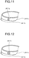
- FIG. 11 is a drawing schematically illustrating the first connector portion 241 in the endoscope system 1 according to the third modification of the first embodiment of the present invention.
- a cutout portion 2411g according to the third modification, as illustrated in FIG. 11 has a shape where the reduced diameter portion 2411c is cut out from the distal end toward the proximal end in an approximately U shape.
- FIG. 12 is a drawing schematically illustrating the first connector portion 241 in the endoscope system 1 according to the fourth modification of the first embodiment of the present invention.
- a cutout portion 2411h according to the fourth modification, as illustrated in FIG. 12 has a hole shape that communicates between an inner surface and the outer peripheral surface of the reduced diameter portion 2411c.
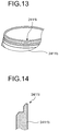
- FIG. 13 is a drawing schematically illustrating the first connector portion 241 in the endoscope system 1 according to the fifth modification of the first embodiment of the present invention.
- FIG. 14 is a cross-sectional view schematically illustrating a part of the first connector portion 241 in the endoscope system 1 according to the fifth modification of the first embodiment of the present invention.
- the cross-sectional view illustrated in FIG. 14 is a cross-sectional view whose cut surface is a planar surface parallel to a center axis (a cylindrical axis) of the coupling portion 2411.
- the cutout portion 2411i has a shape where an outer surface of the reduced diameter portion 2411c (see FIG. 2 ) is cut out over the circumferential direction.
- the cutout portion 2411i as illustrated in FIG. 14 , has a stepped shape in a sectional side view viewed from a direction perpendicular to the center axis of the coupling portion 2411.
- the fifth modification a region where this reduced diameter portion 2411c and the convex portion 32a are contactless in the first locking state is large compared with the above-described first embodiment, thus ensuring further surely returning the state to the normal pressure state.
- the surface at the depressed part of the cutout portion 2411i has a shape orthogonally bent (see FIG. 14 ). However, this may have a shape that forms a curved surface.
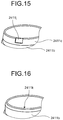
- FIG. 15 is a drawing schematically illustrating the first connector portion 241 in the endoscope system 1 according to the sixth modification of the first embodiment of the present invention.
- a cutout portion 2411j according to the sixth modification, as illustrated in FIG. 15 has a concave shape where a part of the outer peripheral surface of the reduced diameter portion 2411c is depressed to the inner peripheral side.
- FIG. 16 is a drawing schematically illustrating the first connector portion 241 in the endoscope system 1 according to the seventh modification of the first embodiment of the present invention.
- a reduced diameter portion 2411k according to the seventh modification, as illustrated in FIG. 16 is formed such that, compared with the above-described reduced diameter portion 2411c, a length in an extending direction is shortened, and an inclined angle between the outer peripheral surface of the airtightness portion 2411b and the outer peripheral surface of this reduced diameter portion 2411k is increased.
- the outer peripheral surface which is an inclined surface, functions as an airtightness release portion that releases the airtight state between the first connector portion 241 and the water-resistant cap 3.
- FIG. 17 is a drawing schematically illustrating a first connector portion 241a in the endoscope system 1 according to the eighth modification of the first embodiment of the present invention.
- the first connector portion 241a according to the eighth modification includes an expanded diameter portion 24111, instead of the above-described reduced diameter portion 2411c.
- the expanded diameter portion 24111 has a cylindrical shape that extends from the end portion of the airtightness portion 2411b, the end portion at the side different from the base portion 2411a side, and has a diameter that forms an inner surface increases toward the distal end.
- a cutout portion 2411m similar to the above-described cutout portion 2411d, has a cutout shape where the expanded diameter portion 24111 is cut out from a distal end toward a proximal end.
- the cutout portions or the reduced diameter portions according to the above-described first to seventh modifications may be applied to this.
- the eighth modification for example, can obtain the above-described advantageous effect when the first packing 32 is formed at a side of the rib 31d.
- one cutout portion is formed.
- a plurality of cutout portions may be provided.
- the respective cutout portions may have an identical size or different sizes, and, for example, may be a combination of those in the first embodiment and the first to seventh modifications as necessary.
- the endoscope 2 is an ultrasound endoscope where a part of it can be inserted into the subject, and having the function that transmits the ultrasonic pulse toward the subject and receives the ultrasonic echo reflected at the subject to output the echo signal and the function that captures the inside of the subject to output the image signal.
- the above-described structures of the electric connector portion and the water-resistant cap may be applied to an endoscope that has only the function that captures the inside of the subject to output the image signal and an endoscope that has only the function that transmits the ultrasonic pulse toward the subject and receives the ultrasonic echo reflected at the subject to output the echo signal.
- FIG. 18 is a drawing schematically illustrating an endoscope system according to the second embodiment of the present invention.
- An endoscope system 1a is a system that performs the ultrasonic diagnostics inside the subject such as a human using an ultrasound endoscope.
- This endoscope system 1a as illustrated in FIG. 18 , includes an endoscope 2a, the water-resistant cap 3 installed at the endoscope 2a, and the image processing device 4.
- the endoscope 2a as illustrated in FIG. 18 , includes the inserted portion 21, the operating unit 22, the universal cord 23, and a connector 25.
- the operating unit 22 includes the curving knob 221, and includes a first operating unit 260 removably coupled to the universal cord 23, a second operating unit 261 at which the treatment tool insertion port 222 is provided, a third operating unit 262 at which the air supply and water supply port 223 is provided, and a fourth operating unit 263 coupled to the third operating unit 262 at one end and coupled to the inserted portion 21 at the other end.
- the connector 25 is provided at a distal end of the universal cord 23. Then, the connector 25 includes a first connector portion 251 to which a connector portion of a scope cable that holds a plurality of signal cables is coupled, to be configured to be coupled to the above-described image processing device 4 and water-resistant cap 3, and a second connector portion 252 to which a cable at which an optical fiber and the like are arranged is coupled, to be coupled to the light source device.
- FIG. 19 is a drawing schematically illustrating a configuration of a main part of the operating unit in the endoscope system according to the second embodiment of the present invention, and a partial cross-sectional view taken along the line A-A illustrated in FIG. 18 .
- the third operating unit 262 has an end portion at a side coupled to the fourth operating unit 263, and at this end portion, a rotation prevention member 264 that prevents the fourth operating unit 263 from rotating around a center axis (a longitudinal axis of the operating unit 22) of the third operating unit 262 is provided.
- the third operating unit 262 forms a hole having an approximately octagon shape.
- the fourth operating unit 263 has outer peripheries at parts coupled to the third operating unit 262, and at theses outer peripheries, planar portions are formed.
- the rotation prevention member 264 has an approximately-octagon-shaped ring shape, thus ensuring preventing the fourth operating unit 263 from rotating around the center axis of the third operating unit 262. It is not limited to the above-described octagon shape, and it is possible to employ a shape having at least one planar portion and a shape that does not have continuous rotation symmetry, such as an elliptical shape.
- FIG. 20 is a drawing schematically illustrating a configuration of a main part of the operating unit in the endoscope system according to the second embodiment of the present invention, and a cross-sectional view whose cut surface is a planar surface perpendicular to an extending direction of the air supply and water supply port 223.
- the air supply and water supply port 223 holds a water filling base 225 for air supply and water supply, for example, sending liquid into a balloon provided at the distal end (the ultrasound transducer 211) of the inserted portion 21.
- hole 223a having planar portions 223b is formed inside the air supply and water supply port 223, hole 223a having planar portions 223b is formed.
- the water filling base 225 has outer peripheries at parts coupled to the hole 223a, and these outer peripheries form shapes having planar portions 225a provided corresponding to the planar portions 223b of the hole 223a.
- the air supply and water supply port 223 is coupled to the water filling base 225, they are coupled one another with the above-described planar portions 223b and 225a contacting one another, thus ensuring restraining the water filling base 225 from rotating around a center axis of the hole 223a.
- FIG. 21 is a drawing schematically illustrating a configuration of a main part of the inserted portion in the endoscope system according to the second embodiment of the present invention, and a perspective view illustrating a part of the rigid member 212 and the curving portion 213.
- FIG. 22 is a drawing schematically illustrating a configuration of a main part of the inserted portion in the endoscope system according to the second embodiment of the present invention, and a drawing illustrating an enlarged coupling part of the rigid member 212 and the curving portion 213 among the configuration illustrated in FIG. 21.
- FIGS. 21 and 22 illustrate a configuration where an outer coat of the inserted portion 21 has been removed.
- the rigid member 212 includes an ultrasonic functional portion 215 that has an ultrasound transducer 27, a holding port continuous with the ultrasonic functional portion 215 at one end and coupled to the curving portion 213 at the other end to hold an objective lens and an illumination lens, and a tubular endoscope functional portion 216 at which a treatment tool injection hole coupled to the treatment tool insertion port 222 is formed.
- the endoscope functional portion 216 is housed in the curving portion 213 to fit to it, thus being coupled to the curving portion 213.
- the curving portion 213 has a part coupled to the endoscope functional portion 216, and at this part, a caulking portion 213a is formed.
- the caulking portion 213a has a scale shape formed such that a C-shaped slit is formed at a part of the curving portion 213. This caulking portion 213a is pressed onto the endoscope functional portion 216, thus ensuring preventing the rigid member 212 from exiting from the curving portion 213.
- FIG. 23 is a drawing schematically illustrating a configuration of a main part of the ultrasound transducer in the endoscope system according to the second embodiment of the present invention, and a drawing of the inserted portion 21 viewed from a direction perpendicular to a longitudinal axis of the inserted portion 21.
- a first balloon holding groove 215a that is provided at the distal end side of the ultrasound transducer 27 and has a groove shape formed along the circumferential direction
- a second balloon holding groove 215b that is provided at the proximal end side of the ultrasound transducer 27 and has a groove shape formed along the circumferential direction are formed.
- an axis C1 passes through a center of the first balloon holding groove 215a and is parallel to a longitudinal axis of the ultrasonic functional portion 215.
- An axis C2 passes through a center of the second balloon holding groove 215b and is parallel to the longitudinal axis of the ultrasonic functional portion 215.
- a distance d1 is a distance between the axis C1 and the axis C2.
- An axis C3 passes through a center portion in the longitudinal axis direction of the ultrasonic functional portion 215, of the first balloon holding groove 215a and is perpendicular to this longitudinal axis.
- An axis C4 passes through a center portion in the longitudinal axis direction of the ultrasonic functional portion 215, of the second balloon holding groove 215b and is perpendicular to this longitudinal axis.
- a distance d2 is a distance between the axis C3 and the axis C4.
- the distances d1 and d2 satisfy a relation that d1/d2 ⁇ 0.1. The satisfaction of this relation, when one end and the other end of a balloon are arranged at the first balloon holding groove 215a and the second balloon holding groove 215b, restrains a one-sided bulge and the like to ensure efficiently expanding or contracting the balloon.
- FIG. 24 is a drawing schematically illustrating a configuration of a main part of the connector portion in the endoscope system according to the second embodiment of the present invention, and a drawing illustrating a configuration of the first connector portion 251.
- FIG. 25 is a cross-sectional view of the first connector portion taken along the line B-B illustrated in FIG. 24 .
- the first connector portion 251 includes an outer cylinder 253 having a tubular shape, and an inner cylinder 254 provided inside the outer cylinder and is formed such that a plurality of extending portions 254a that extend in a central axis direction are formed along the circumferential direction.
- the first connector portion 251 is configured to be coupled to only the connector portion of the scope cable having patterns corresponding to coupling patterns by disposition of the base pins 253a and the extending portions 254a, or the water-resistant cap 3. This can prevent the first connector portion 251 from being improperly coupled to the connector portion of the scope cable and the water-resistant cap 3.
- an insulating member 255 that is formed using resin having an insulation property, has a tubular shape with a closed bottom at one-side, and includes a cutout portion 255a formed such that a part of a side surface of the insulating member 255 is cut out is provided.
- This insulating member 255 maintains ease of assembly of the first connector portion 251, and the cable is arranged via the cutout portion 255a where a part of the side surface that extends from a bottom portion, thus ensuring a creepage distance to have more surely the insulating property between a cable of a patient ground and a cable that transmits the ultrasonic signal.
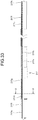
- FIGS. 26 to 28 are drawings schematically illustrating a configuration of a main part of the operating unit in the endoscope system according to the second embodiment of the present invention, and a drawing where an outer coat of the second operating unit 261 has been removed.
- FIG. 28 is a cross-sectional view whose cut surface is a planar surface that passes through an image quality adjustment hole 2610 illustrated in FIG. 27 and is parallel to an optical axis direction of a lens.
- the second operating unit 261 internally includes a fiber holding portion 261a that extends from the distal end of the inserted portion 21 to hold an optical fiber 28 for optically transmitting the image signal, an optical element holding portion 261c that holds a plurality of lenses, and a plurality of spacer rings and imaging elements IM, a lens holding portion 261d supported to the fiber holding portion 261a to hold at least one lens, a coiled spring 261e that interposes between the fiber holding portion 261a and the optical element holding portion 261c, and a cover 261b that holds the fiber holding portion 261a and the optical element holding portion 261c.
- the image quality adjustment hole 2610 is formed between the fiber holding portion 261a and the optical element holding portion 261c, and corresponding to an arranging position of the coiled spring 261e.
- the image quality adjustment hole 2610 is configured to be sealed by a sealing member 261f removably provided at the cover 261b.
- the sealing member 261f is fixedly secured to the cover 261b, for example, by screwing.
- the seal of the image quality adjustment hole 2610 by the sealing member 261f ensures preventing impurities such as waste and dust from attaching a lens surface, and light from an outside of the cover 261b from entering the plurality of lenses and imaging elements IM held by the optical element holding portion 261c.
- the endoscope 2a is used in a state sealed by the sealing member 261f.
- the sealing member 261f is removed, thus making a state that can take in the light from the image quality adjustment hole 2610 and between wire rods of the coiled spring 261e. This facilitates the image quality adjustment process.
- FIG. 29 is a drawing schematically illustrating a configuration of a main part of the ultrasound transducer in the endoscope system according to the second embodiment of the present invention, and a drawing illustrating a configuration of the ultrasonic functional portion 215 removed from the endoscope functional portion 216.
- FIG. 30 is a partial cross-sectional view taken along the line C-C illustrated in FIG. 29 .
- FIG. 31 is a drawing schematically illustrating a configuration of a main part of the ultrasound transducer in the endoscope system according to the second embodiment of the present invention, and a cross-sectional view whose cut surface is a planar surface parallel to a paper surface of FIG. 29 and illustrating an acoustic lens and first and second wall portions.
- the ultrasound transducer 27 is a convex-type ultrasound transducer as illustrated in FIG. 21 and a one-dimensional array (a 1D array) where a plurality of piezoelectric elements 271 are arranged in line.
- the ultrasound transducer 27 includes the plurality of piezoelectric elements 271 that have prismatic shapes and are formed by being arranged with longitudinal directions together, a plurality of first acoustic matching layers 272 each provided at an outer surface side of this ultrasound transducer 27 with respect to the piezoelectric elements 271, a second acoustic matching layer 273 provided at a side opposed to a side that contacts the piezoelectric elements 271, of the plurality of first acoustic matching layers 272, a backing material 274 provided at a side opposed to a side that contacts the first acoustic matching layers 272, of the piezoelectric elements 271 and filled between the piezoelectric elements 271, and an acoustic lens 275 provided at a side opposed to a side that contacts the first acoustic matching layers 272, of the second acoustic matching layer 273.
- the formation of the first acoustic matching layers 272 and the second acoustic matching layer 273 using the super engineering plastic ensures improving chemical resistance and mechanical strength, compared with a case that uses the epoxy resin.
- the backing material 274 attenuates unnecessary ultrasonic vibration generated by operation of the piezoelectric elements 271.
- the backing material 274 is formed using a material whose attenuation rate is large, for example, the epoxy resin where a filler such as alumina and zirconia is dispersed, and a rubber where the above-described filler is dispersed.
- the backing material 274 is formed such that liquid material for the backing material is cast into a hollow space formed by a first wall portion 27a and a second wall portion 27b (see FIG. 31 ) to be hardened.
- the first wall portion 27a and the second wall portion 27b are formed using polyphenylene ether. This ensures thinning thicknesses compared with a case that uses glass epoxy resin with a copper foil.
- the first wall portion 27a and the second wall portion 27b do not include metal, thus eliminating a need for wiring with a housing and a ground to facilitate the fabrication.
- an angle ⁇ 1 that forms a corner portion closest to a balloon pipe line 215c formed at the ultrasonic functional portion 215 is formed larger than angles (for example, an angle ⁇ 2 ) of other corner portions.
- this can restrain thinning of a wall thickness of the housing of the ultrasonic functional portion 215 by the balloon pipe line 215c to ensure strength of the housing. This can also improve storing ability of the components inside the ultrasonic functional portion 215.
- FIG. 32 is a drawing schematically illustrating a configuration of a main part of the ultrasound transducer in the endoscope system according to the second embodiment of the present invention, and a drawing illustrating an array of the piezoelectric elements 271, the first acoustic matching layers 272, and the second acoustic matching layer 273.
- an element width of the piezoelectric element 271 in an arranging direction (a scanning direction) of the plurality of piezoelectric elements 271 is d3
- a groove width between the piezoelectric elements 271 adjacent to one another in the arranging direction is d4
- a relation that d4/d3 ⁇ 0.4 is satisfied.
- the satisfaction of this relation maintains the number of elements and a pitch and reduces a curvature radius of the ultrasound transducer 27 to restrain deterioration of the image quality, thus ensuring downsizing the ultrasound transducer 27.
- FIG. 33 is a drawing schematically illustrating a configuration of a main part of the inserted portion in the endoscope system according to the second embodiment of the present invention, and a partial cross-sectional view illustrating a configuration at the distal end side of a cable that contains one or a plurality of signal cables that extend from the ultrasound transducer 27, as one example.
- FIG. 34 is a cross-sectional view of a cable sheath taken along the line D-D illustrated in FIG. 33 . The following describes the configuration at the distal end side of the cable.
- the proximal end side (a universal cord side) also may have a similar configuration.
- a cable 217 includes a comprehensive shield 217b that is a metal braid that coats a part except for the distal end side, of a coaxial cable bundle 217a that contains one or a plurality of signal cables that extend from the ultrasound transducer 27, a cable sheath 217c that coats the comprehensive shield 217b over an approximately entire length, except for a part of the proximal end, a first coated portion 217d that coats a part at the distal end side of the coaxial cable bundle 217a and including a border between the coaxial cable bundle 217a and the comprehensive shield 217b, a second coated portion 217e that coats the coaxial cable bundle 217a and the distal end side of the first coated portion 217d, a protective member 217f that includes the border between the coaxial cable bundle 217a and the comprehensive shield 217b in the radial direction and coats the cable sheath 217c, the first coated portion 217d, the second coated portion 217
- the cable sheath 217c is provided over a whole circumference and the approximately entire length of the comprehensive shield 217b.
- the cable sheath 217c is formed with a material that fulfills withstand voltage performance, or formed so as to have a thickness that fulfills the withstand voltage performance.
- the first coated portion 217d, the second coated portion 217e, the third coated portion 217g, and the fourth coated portion 217h are formed using heat shrinkable tubes.
- the first coated portion 217d prevents damage of the coaxial cable bundle 217a and the second coated portion 217e due to unraveling of the metal braid at a part exposed from the cable sheath, of the comprehensive shield 217b.
- the second coated portion 217e electrically insulates the distal end side of the coaxial cable bundle 217a.
- a comprehensive cable coupled to the first connector portion 251 has a configuration identical to that of the first coated portion 217d.
- the protective member 217f which is formed using polyimide or the like, is provided over a half circumference of the cable 217.
- the protective member 217f prevents damage of the cable sheath 217c, the first coated portion 217d, the second coated portion 217e, and the fourth coated portion 217h. The disposition only over the half circumference restrains the cable 217 from increasing a diameter.
- the third coated portion 217g which is formed with a heat shrinkable tube, forms an outer-most coat of the cable 217.
- a material that fulfills the withstand voltage performance or a material having a thickness that fulfills the withstand voltage performance is employed.
- the third coated portion 217g electrically insulates the cable 217 at this coated part.
- the fourth coated portion 217h which is formed using a heat shrinkable tube, is provided over the whole circumference and the approximately entire length of the cable sheath 217c.
- the heat shrinkable tube is preferred to be formed using a transparent material. The formation of the fourth coated portion 217h ensures preventing the damage of the cable sheath 217c.
- the endoscope system according to the present invention is effective for easily removing the water-resistant cap from the electric connector portion of the endoscope whose inside is in the negative pressure state.
Landscapes
- Health & Medical Sciences (AREA)
- Life Sciences & Earth Sciences (AREA)
- Surgery (AREA)
- Physics & Mathematics (AREA)
- Biomedical Technology (AREA)
- Molecular Biology (AREA)
- Pathology (AREA)
- Radiology & Medical Imaging (AREA)
- Nuclear Medicine, Radiotherapy & Molecular Imaging (AREA)
- Engineering & Computer Science (AREA)
- Biophysics (AREA)
- Heart & Thoracic Surgery (AREA)
- Medical Informatics (AREA)
- Optics & Photonics (AREA)
- Animal Behavior & Ethology (AREA)
- General Health & Medical Sciences (AREA)
- Public Health (AREA)
- Veterinary Medicine (AREA)
- Astronomy & Astrophysics (AREA)
- General Physics & Mathematics (AREA)
- Endoscopes (AREA)
- Ultra Sonic Daignosis Equipment (AREA)
Abstract
Description
- The present invention relates to an endoscope system.
- Conventionally, in the field of medicine, an endoscope system is employed when an inside of a subject such as a patient is observed. The endoscope system includes an endoscope, for example, where an image sensor is provided at a distal end and includes an inserted portion to be inserted into a body cavity of the subject, and an image processing device, which is coupled to the endoscope via a cable and performs image processing of an in-vivo image corresponding to an imaging signal generated by the image sensor to display the in-vivo image on a display unit or the like.
- On the endoscope, which the cable is removed before and after the observation inside the subject, a sterilization treatment by, what is called, an autoclave or the like and a disinfectant treatment by an antiseptic solution are performed. In this respect, such that liquid such as water vapor and the antiseptic solution does not internally enter from an electric connector of the endoscope, a water-resistant cap is installed at an electric connector portion of the endoscope (for example, see Patent Literature 1). When an elastic member, such as an O-ring, provided on a wall surface of the water-resistant cap is interposed between the electric connector portion of the endoscope and the water-resistant cap, for example, the electric connector portion of the endoscope and the water-resistant cap have a mutually airtight state. Citation List
- Patent Literature 1:
JP 5-300870 A - Now, in the sterilization by the autoclave or the like, negative pressure processing is performed before a sterilization process, and then, the sterilization process is performed under a positive pressure environment. After the sterilization, when the water-resistant cap is attempted to be removed from the electric connector portion of the endoscope whose inside is in a negative pressure state, since the O-ring sticks to the wall surface of the endoscope, there is a problem that the water-resistant cap cannot be removed from the electric connector portion of the endoscope.
- The present invention has been made in view of the above-described problem. An object of the present invention is to provide an endoscope system that ensures easily removing a water-resistant cap from an electric connector portion of an endoscope whose inside is in a negative pressure state.
- To solve the problem described above and to achieve the object, an endoscope system according to the present invention includes: an endoscope including an inserted portion to be inserted into an inside of a subject and a connector portion for electrically coupling to an external connector, the endoscope being configured to observe the inside of the subject; and a water-resistant cap configured to be airtightly installed at the connector portion. The connector portion includes: a base portion having a tubular shape; a tubular sleeve portion extending from the base portion and having a diameter smaller than a diameter of the base portion; and an airtightness release portion provided at an end portion of the sleeve portion and configured to release an airtight state between the connector portion and the water-resistant cap. The water-resistant cap includes: a tubular cap main body having a closed bottom at one side; and an abutting portion provided inside the cap main body and configured to abut on the sleeve portion. When the water-resistant cap is installed at the connector portion, the endoscope system takes any state of a first state where the abutting portion abuts on the sleeve portion on a side of the base portion with respect to the airtightness release portion to hold an airtightness between the water-resistant cap and the connector portion, and a second state where the abutting portion abuts on or faces the sleeve portion including the airtightness release portion to make non-airtight between the water-resistant cap and the connector portion.
- In the endoscope system according to the present invention, the sleeve portion includes: an airtightness portion that extends from the base portion, has a tubular shape having a diameter smaller than the diameter of the base portion, and is configured to be airtightly coupled to the abutting portion; and a reduced diameter portion that has a tubular shape that extends from an end portion of the airtightness portion, the end portion of the airtightness portion being at a side different from the side of the base portion, the reduced diameter portion having an outer peripheral surface with a diameter decreasing toward a distal end, and the airtightness release portion is provided at the reduced diameter portion.
- In the endoscope system according to the present invention, the airtightness release portion has a cutout shape where the sleeve portion is cut out from a distal end toward a proximal end.
- In the endoscope system according to the present invention, the airtightness release portion has a chamfered end portion continuous with the distal end of the sleeve portion.
- In the endoscope system according to the present invention, the airtightness release portion has a hole.
- In the endoscope system according to the present invention, the airtightness release portion has a concave shape where a part of the outer peripheral surface is depressed to an inner peripheral side.
- In the endoscope system according to the present invention, the airtightness release portion is formed such that a part of the outer peripheral surface is circumferentially depressed to the inner peripheral side.
- The present invention provides an advantageous effect that a water-resistant cap can be easily removed from an electric connector portion of an endoscope whose inside is in a negative pressure state.
-
-
FIG. 1 is a drawing schematically illustrating an endoscope system according to a first embodiment of the present invention. -
FIG. 2 is a perspective view schematically illustrating a first connector portion in the endoscope system according to the first embodiment of the present invention. -
FIG. 3 is a perspective view illustrating an internal structure of a water-resistant cap in the endoscope system according to the first embodiment of the present invention. -
FIG. 4 is a cross-sectional view illustrating a state where the water-resistant cap illustrated inFIG. 3 is installed at the first connector portion illustrated inFIG. 2 . -
FIG. 5A is a drawing that describes the installation of the water-resistant cap illustrated inFIG. 3 with respect to the first connector portion illustrated inFIG. 2 . -
FIG. 5B is a drawing that describes the installation of the water-resistant cap illustrated inFIG. 3 with respect to the first connector portion illustrated inFIG. 2 . -
FIG. 5C is a drawing that describes the installation of the water-resistant cap illustrated inFIG. 3 with respect to the first connector portion illustrated inFIG. 2 . -
FIG. 6 is a drawing that describes the installation of the water-resistant cap illustrated inFIG. 3 with respect to the first connector portion illustrated inFIG. 2 . -
FIG. 7 is a drawing that describes the installation of the water-resistant cap illustrated inFIG. 3 with respect to the first connector portion illustrated inFIG. 2 . -
FIG. 8 is a drawing that describes an installation of a conventional water-resistant cap with respect to a conventional electric connector portion. -
FIG. 9 is a drawing schematically illustrating a first connector portion of an endoscope system according to a first modification of the first embodiment of the present invention. -
FIG. 10 is a drawing schematically illustrating a first connector portion of an endoscope system according to a second modification of the first embodiment of the present invention. -
FIG. 11 is a drawing schematically illustrating a first connector portion of an endoscope system according to a third modification of the first embodiment of the present invention. -
FIG. 12 is a drawing schematically illustrating a first connector portion of an endoscope system according to a fourth modification of the first embodiment of the present invention. -
FIG. 13 is a drawing schematically illustrating a first connector portion of an endoscope system according to a fifth modification of the first embodiment of the present invention. -
FIG. 14 is a cross-sectional view schematically illustrating a part of the first connector portion in the endoscope system according to the fifth modification of the first embodiment of the present invention. -
FIG. 15 is a drawing schematically illustrating a first connector portion of an endoscope system according to a sixth modification of the first embodiment of the present invention. -
FIG. 16 is a drawing schematically illustrating a first connector portion of an endoscope system according to a seventh modification of the first embodiment of the present invention. -
FIG. 17 is a drawing schematically illustrating a first connector portion of an endoscope system according to an eighth modification of the first embodiment of the present invention. -
FIG. 18 is a drawing schematically illustrating an endoscope system according to a second embodiment of the present invention. -
FIG. 19 is a drawing schematically illustrating a configuration of a main part of an operating unit in the endoscope system according to the second embodiment of the present invention. -
FIG. 20 is a drawing schematically illustrating a configuration of a main part of the operating unit in the endoscope system according to the second embodiment of the present invention. -
FIG. 21 is a drawing schematically illustrating a configuration of a main part of an inserted portion in the endoscope system according to the second embodiment of the present invention. -
FIG. 22 is a drawing schematically illustrating a configuration of a main part of the inserted portion in the endoscope system according to the second embodiment of the present invention. -
FIG. 23 is a drawing schematically illustrating a configuration of a main part of an ultrasound transducer in the endoscope system according to the second embodiment of the present invention. -
FIG. 24 is a drawing schematically illustrating a configuration of a main part of a connector portion in the endoscope system according to the second embodiment of the present invention. -
FIG. 25 is a cross-sectional view of the first connector portion taken along the line B-B illustrated inFIG. 24 . -
FIG. 26 is a drawing schematically illustrating a configuration of a main part of the operating unit in the endoscope system according to the second embodiment of the present invention. -
FIG. 27 is a drawing schematically illustrating a configuration of a main part of the operating unit in the endoscope system according to the second embodiment of the present invention. -
FIG. 28 is a drawing schematically illustrating a configuration of a main part of the operating unit in the endoscope system according to the second embodiment of the present invention. -
FIG. 29 is a drawing schematically illustrating a configuration of a main part of the ultrasound transducer in the endoscope system according to the second embodiment of the present invention. -
FIG. 30 is a partial cross-sectional view taken along the line C-C illustrated inFIG. 29 . -
FIG. 31 is a drawing schematically illustrating a configuration of a main part of the ultrasound transducer in the endoscope system according to the second embodiment of the present invention. -
FIG. 32 is a drawing schematically illustrating a configuration of a main part of the ultrasound transducer in the endoscope system according to the second embodiment of the present invention. -
FIG. 33 is a drawing schematically illustrating a configuration of a main part of the inserted portion in the endoscope system according to the second embodiment of the present invention. -
FIG. 34 is a cross-sectional view of a cable sheath taken along the line D-D illustrated inFIG. 33 . Description of Embodiments - The following describes modes for carrying out the invention (hereinafter referred to as "embodiments") with reference to the attached drawings.
-
FIG. 1 is a drawing schematically illustrating anendoscope system 1 according to a first embodiment of the present invention. Theendoscope system 1 is a system that uses a property of an ultrasonic sound wave to apply the ultrasonic sound wave to a subject, and then visualizes its reflection. Thisendoscope system 1, as illustrated inFIG. 1 , includes anendoscope 2 and a water-resistant cap 3 to be installed at theendoscope 2. Theendoscope 2 is an ultrasound endoscope, which is partially insertable into the subject and has a function that transmits the ultrasonic sound wave inside the subject and receives the reflection (an echo) reflected at the subject to output an echo signal. Theendoscope 2 is configured to be coupled to animage processing device 4 that receives the echo signal to generate an ultrasound image corresponding to this echo signal, via a cable. - The
endoscope 2 has a distal end portion including anultrasound transducer 211 that converts an electrical pulse signal received from a processing device into an ultrasonic pulse to irradiate the subject with it and converts the ultrasonic echo reflected at the subject into an electrical echo signal expressed in a voltage change to output it. Theultrasound transducer 211 may be any of a convex transducer, a linear transducer, and a radial transducer. Theendoscope 2 may be one that causes the ultrasound transducer to mechanically scan, or may be one that includes a plurality of elements in an array shape as the ultrasound transducer to cause them to mechanically scan by electronically switching elements related to transmitting and receiving or by delaying transmitting and receiving of the respective elements. - The
endoscope 2, which usually includes an imaging optical system and an imaging element, is inserted into an alimentary canals (an esophagus, a stomach, a duodenum, and a large intestine) or respiratory organs (a trachea and a bronchus) of the subject to ensure capturing the alimentary canals, the respiratory organs, and their peripheral organs (a pancreas, a gallbladder, a bile duct, a biliary tract, a lymph node, a mediastinum organ, a blood vessel, and the like). It is not limited to theendoscope 2, and an ultrasonic probe that does not include the imaging optical system and the imaging element may be employed. - The
endoscope 2, as illustrated inFIG. 1 , includes an insertedportion 21, an operatingunit 22, auniversal cord 23, and aconnector 24. A "distal end side" described below means a distal end side of the insertedportion 21. A "proximal end side" described below means a side separating from the distal end of the insertedportion 21. - The inserted
portion 21 is a part inserted into the subject. This insertedportion 21, as illustrated inFIG. 1 , includes arigid member 212 that holds theultrasound transducer 211 at a distal end, a curvingportion 213 coupled to the proximal end side of therigid member 212 to be configured to curve, and aflexible tube portion 214 coupled to the proximal end side of the curvingportion 213 to have flexibility. - Here, inside the inserted
portion 21, although a specific illustration is omitted, a light guide that transmits illuminating light supplied from a light source device (not illustrated) and a plurality of signal cables that transmit various signals are drawn, and a processing tool insertion path for inserting a treatment tool is formed. - The operating
unit 22 is a part coupled to the proximal end side of the insertedportion 21 to accept various operations from a doctor or the like. The operations, for example, include an angle operation, an air supply and water supply operation, and a suction operation. This operatingunit 22, as illustrated inFIG. 1 , includes acurving knob 221 for curving operation on the curvingportion 213. At theoperating unit 22, a treatmenttool insertion port 222 that communicates with the treatment tool insertion path formed inside the insertedportion 21 to insert the treatment tool into this treatment tool insertion path, and an air supply andwater supply port 223 that communicates with an air supply and water supply path formed inside the insertedportion 21 to pass gas or liquid through this air supply and water supply path are formed. - Inside the
universal cord 23, a plurality of signal cables that extend from the operatingunit 22 to transmit various signals and a cable at which an optical fiber and the like that transmit the illuminating light supplied from the light source device are arranged are drawn. - The
connector 24 is provided at a distal end of theuniversal cord 23. Then, theconnector 24 includes afirst connector portion 241 to which a connector portion of a scope cable that holds a plurality of signal cables is coupled, to be coupled to the above-describedimage processing device 4, and asecond connector portion 242 to which a cable at which an optical fiber and the like are arranged is coupled, to be coupled to the light source device. - The following describes a structure of the
first connector portion 241.FIG. 2 is a perspective view schematically illustrating thefirst connector portion 241 in theendoscope system 1 according to the first embodiment of the present invention. Thefirst connector portion 241 is an electric connector for being electrically coupled to the plurality of signal cables internally mounted on theuniversal cord 23. Thefirst connector portion 241, as illustrated inFIG. 2 , has a cylindrical shape that covers a terminal Te (seeFIG. 4 ) electrically coupled to the plurality of signal cables. Although a specific illustration is omitted, the terminal Te is arranged so as to airtightly obstruct an inside of thefirst connector portion 241 by an O-ring or the like. - the
first connector portion 241 includes acoupling portion 2411 coupled to a connector portion (not illustrated) of the scope cable coupled to theimage processing device 4, and a protrudingportion 2412 formed by projecting outside from a proximal end (an end portion at a lower side inFIG. 2 ) of thecoupling portion 2411. In thefirst connector portion 241, the protrudingportion 2412 fits into an aperture formed at aconnector casing 240 that constitutes theconnector 24, and this aperture is airtightly obstructed by an O-ring or the like. - The
coupling portion 2411, as illustrated inFIG. 2 , includes a cylindrically-shapedbase portion 2411a that extends from the protrudingportion 2412, anairtightness portion 2411b that extends from thebase portion 2411a toward a side different from a side of the protrudingportion 2412, has a cylindrical shape having a diameter smaller than a diameter of thebase portion 2411a, and is configured to be airtightly coupled to the water-resistant cap 3 described later, and a reduceddiameter portion 2411c that has a cylindrical shape that extends from an end portion of theairtightness portion 2411b being at a side different from a side of thebase portion 2411a and whose diameter that forms an outer peripheral surface decreases toward an distal end. At the reduceddiameter portion 2411c, acutout portion 2411d cut out from the distal end toward a proximal end is formed. Thecutout portion 2411d forms an arc-shaped cutout surface that forms an edge end of the reduceddiameter portion 2411c. In the first embodiment, theairtightness portion 2411b and the reduceddiameter portion 2411c constitute a sleeve portion. - At the
base portion 2411a, two lockingpins 2413 for locking the water-resistant cap 3 (seeFIG. 3 ) on thefirst connector portion 241 are installed so as to project from the outer peripheral surface. - On the
endoscope 2, as described above, before and after the ultrasonic diagnostics inside the subject, the scope cable is removed from thefirst connector portion 241, and then, the sterilization treatment by an autoclave or the like and the disinfectant treatment by an antiseptic solution are performed. In this respect, In order to provide two functions: a watertight function that prevents liquid such as water vapor and the antiseptic solution from entering inside thefirst connector portion 241 and an airtight function that prevents sterilization gas from internally entering, the water-resistant cap 3 (seeFIG. 3 ) is installed at thefirst connector portion 241. -
FIG. 3 is a perspective view illustrating an internal structure of the water-resistant cap 3 installed at thefirst connector portion 241.FIG. 4 is a cross-sectional view illustrating a state where the water-resistant cap 3 has been installed at thefirst connector portion 241. The water-resistant cap 3, as illustrated inFIG. 3 andFIG. 4 , includes a capmain body 31, a first packing 32 (an abutting portion), a cammain body 33, and asecond packing 34. - The cap
main body 31, as illustrated inFIG. 3 andFIG. 4 , includes a cylindrically-shapedsidewall portion 31a that allows thecoupling portion 2411 to be inserted and abottom portion 31b that obstructs one end of thesidewall portion 31a, and is formed in a cylindrical shape with a closed bottom at one side having anaperture portion 31c at the other end of thesidewall portion 31a. On an inner surface of thebottom portion 31b (a bottom surface of the cap main body 31),ribs 31d are provided upright. Then, as illustrated inFIG. 4 , when the water-resistant cap 3 is installed at thefirst connector portion 241, thisrib 31d houses a part of thecoupling portion 2411 in a hollow space formed by thisrib 31d and thesidewall portion 31a. - The
first packing 32, which has a ring shape, is installed on an inner surface of thesidewall portion 31a. As illustrated inFIG. 4 , thefirst packing 32 includes aconvex portion 32a that abuts on an outer peripheral surface of thecoupling portion 2411, specifically, an outer peripheral surface of theairtightness portion 2411b to keep airtightness of the inside of thefirst connector portion 241 when the water-resistant cap 3 is installed at thefirst connector portion 241. - The cam
main body 33, which has a cylindrical shape that allows thecoupling portion 2411 to be inserted, is installed at a side of theaperture portion 31c on the inner surface of thesidewall portion 31a. At this cammain body 33, as illustrated inFIG. 3 , two lockinggrooves 33a into which the two lockingpins 2413 are each inserted are formed. - Each of the two locking
grooves 33a, as illustrated inFIG. 3 , has an approximately L shape including afirst locking groove 331 that extends from one end (an end portion at theaperture portion 31c side) toward the other end (an end portion at a side of thebottom portion 31b), and asecond locking groove 332 that extends from thefirst locking groove 331 in a rotation direction centering a center axis (not illustrated) of the cammain body 33 and with being inclined toward thebottom portion 31b side. That is, in the first embodiment, as a locking structure of thefirst connector portion 241 and the water-resistant cap 3, a bayonet-type locking structure is employed. - The
second packing 34, which has a ring shape, is installed at theaperture portion 31c in a state where a part of thesecond packing 34 is inserted into a clearance between the cammain body 33 and the inner surface of thesidewall portion 31a. Then, as illustrated inFIG. 4 , when the water-resistant cap 3 is installed at thefirst connector portion 241, thesecond packing 34 abuts on the protrudingportion 2412 to keep the airtightness of the inside of thefirst connector portion 241. - Subsequently, the installation of the water-
resistant cap 3 with respect to thefirst connector portion 241 will be described with reference toFIGS. 5 to 8 .FIGS. 5A to 5C are drawings that describe the installation of the water-resistant cap 3 with respect to thefirst connector portion 241. - When the water-
resistant cap 3 is installed at thefirst connector portion 241, first, as illustrated inFIG. 5A , the water-resistant cap 3 is fitted in thefirst connector portion 241. In this respect, thelocking pin 2413 becomes in a state housed in the first locking groove 331 (hereinafter, referred to as a first locking state). -
FIG. 6 is a drawing that describes the installation of the water-resistant cap 3 with respect to thefirst connector portion 241, and a cross-sectional view illustrating a positional relation between thefirst packing 32 and thecoupling portion 2411 in the first locking state. In the first locking state, as illustrated inFIG. 6 , theconvex portion 32a of thefirst packing 32 abuts on the reduceddiameter portion 2411c, or is arranged at a position faced the reduceddiameter portion 2411c. In view of this, the first locking state makes non-airtight between thefirst connector portion 241 and the water-resistant cap 3, and does not become in the airtight state. - Thereafter, as illustrated in
FIG. 5B , the water-resistant cap 3 is rotated along a forming direction of thesecond locking groove 332 with respect to thefirst connector portion 241. In this respect, thelocking pin 2413 moves along thesecond locking groove 331. Accordingly, the water-resistant cap 3 is pushed into a direction approaching thefirst connector portion 241. Hereinafter, a locking state where thelocking pin 2413 has moved to an end portion of thesecond locking groove 332 being an end portion at a side different from a side of thefirst locking groove 331 is referred to as a second locking state (seeFIG. 5C ). - In the second locking state, as illustrated in
FIG. 4 , theconvex portion 32a of thefirst packing 32 is arranged at a position abutting on the outer peripheral surface of theairtightness portion 2411b to be in a state where the airtightness inside thefirst connector portion 241 is kept. In this second locking state, a negative pressure state is made, for example, by a suction inside of theendoscope 2, to sterilize theendoscope 2. - After the sterilization treatment is terminated, an operator rotates the water-
resistant cap 3 to change the state from the second locking state to the first locking state, and then removes the water-resistant cap 3 from thefirst connector portion 241. -
FIG. 7 is a drawing that describes the installation of the water-resistant cap 3 with respect to thefirst connector portion 241, and a cross-sectional view illustrating a positional relation between thefirst packing 32 and thecoupling portion 2411 in the first locking state after the sterilization treatment. In the first locking state after the sterilization treatment or the disinfectant treatment, as illustrated inFIG. 7 , a part of theconvex portion 32a of thefirst packing 32 is arranged at a position faced thecutout portion 2411d of the reduceddiameter portion 2411c. Thus, the airtight state between theconvex portion 32a and thecoupling portion 2411 is released to return the negative pressure state of thefirst connector portion 241 to a normal pressure state. Thus, thecutout portion 2411d functions as an airtightness release portion configured to release the airtight state between thefirst connector portion 241 and the water-resistant cap 3. -
FIG. 8 is a drawing that describes an installation of a conventional water-resistant cap with respect to a conventional electric connector portion. Compared toFIG. 7 , in a case of the reduceddiameter portion 2411c that does not include thecutout portion 2411d, when the water-resistant cap 3 is rotated to change the state from the second locking state to the first locking state, theconvex portion 32a is pulled to a side of the reduceddiameter portion 2411c in a state where theconvex portion 32a is attached to theairtightness portion 2411b. Thus, for example, as illustrated inFIG. 8 , theconvex portion 32a is attached to theairtightness portion 2411b or the reduceddiameter portion 2411c to be in a state where the airtightness is kept. In view of this, even when the water-resistant cap 3 is rotated to make the first locking state, the airtight state (the negative pressure state) of thefirst connector portion 241 remains to be kept. Thus, sometimes, the water-resistant cap 3 cannot be removed from thefirst connector portion 241. - According to the above-described first embodiment of the present invention, in the connector portion (the first connector portion 241) of the
endoscope 2, thecutout portion 2411d where a part of the reduceddiameter portion 2411c is cut out is formed. When the water-resistant cap 3 is rotated to change the state from the second locking state to the first locking state, the airtight state between theconvex portion 32a of thefirst packing 32 and the reduceddiameter portion 2411c is released, thus ensuring easily removing a water-resistant cap from an endoscope whose inside is in the negative pressure state. - According to the first embodiment, the
cutout portion 2411d is formed at the reduceddiameter portion 2411c, thus, as described above, ensuring easily removing the water-resistant cap from an electric connector portion of the endoscope, and ensuring surely keeping the airtight state between the water-resistant cap 3 and thefirst connector portion 241 when the water-resistant cap 3 becomes in the second locking state, specifically the airtight state between theconvex portion 32a and theairtightness portion 2411b. - According to the first embodiment, the diameter of the reduced
diameter portion 2411c is reduced toward the distal end. Thus, the reduceddiameter portion 2411c functions as a guide unit when theconvex portion 32a and the cammain body 33 are installed at thefirst connector portion 241, and damage of theconvex portion 32a in accordance with this installation can be restrained. - In the above-described first embodiment, the
cutout portion 2411d is described as one where the reduceddiameter portion 2411c is cut out in an arc shape (an approximately semicircular shape). However, thecutout portion 2411d is not limited to this. The following describes modifications of the first embodiment of the present invention. - Subsequently, a first modification of the first embodiment of the present invention will be described.
FIG. 9 is a drawing schematically illustrating thefirst connector portion 241 in theendoscope system 1 according to the first modification of the first embodiment of the present invention. The first modification has a shape where an edge end of thecutout portion 2411d is chamfered. Acutout portion 2411e according to the first modification, as illustrated inFIG. 9 , has a shape where the reduceddiameter portion 2411c is cut out from the distal end toward the proximal end, and furthermore, both ends of thecutout portion 2411e continuous with the distal end of the reduceddiameter portion 2411c in a circumferential direction are chamfered. According to the first modification, when the water-resistant cap 3 is installed at thefirst connector portion 241, the damage of theconvex portion 32a in accordance with this installation can be further surely restrained. - Subsequently, a second modification of the first embodiment of the present invention will be described.
FIG. 10 is a drawing schematically illustrating thefirst connector portion 241 in theendoscope system 1 according to the second modification of the first embodiment of the present invention. Acutout portion 2411f according to the second modification, as illustrated inFIG. 10 , has a shape where the reduceddiameter portion 2411c is cut out from the distal end toward the proximal end in a V shape. - Subsequently, a third modification of the first embodiment of the present invention will be described.
FIG. 11 is a drawing schematically illustrating thefirst connector portion 241 in theendoscope system 1 according to the third modification of the first embodiment of the present invention. Acutout portion 2411g according to the third modification, as illustrated inFIG. 11 , has a shape where the reduceddiameter portion 2411c is cut out from the distal end toward the proximal end in an approximately U shape. - Subsequently, a fourth modification of the first embodiment of the present invention will be described.
FIG. 12 is a drawing schematically illustrating thefirst connector portion 241 in theendoscope system 1 according to the fourth modification of the first embodiment of the present invention. Acutout portion 2411h according to the fourth modification, as illustrated inFIG. 12 , has a hole shape that communicates between an inner surface and the outer peripheral surface of the reduceddiameter portion 2411c. - Subsequently, a fifth modification of the first embodiment of the present invention will be described.
FIG. 13 is a drawing schematically illustrating thefirst connector portion 241 in theendoscope system 1 according to the fifth modification of the first embodiment of the present invention.FIG. 14 is a cross-sectional view schematically illustrating a part of thefirst connector portion 241 in theendoscope system 1 according to the fifth modification of the first embodiment of the present invention. The cross-sectional view illustrated inFIG. 14 is a cross-sectional view whose cut surface is a planar surface parallel to a center axis (a cylindrical axis) of thecoupling portion 2411. Acutout portion 2411i according to the fifth modification, as illustrated inFIG. 13 , has a concave shape where a part of the above-described outer peripheral surface of the reduceddiameter portion 2411c is depressed to an inner peripheral side over the circumferential direction. In other words, thecutout portion 2411i has a shape where an outer surface of the reduceddiameter portion 2411c (seeFIG. 2 ) is cut out over the circumferential direction. Thecutout portion 2411i, as illustrated inFIG. 14 , has a stepped shape in a sectional side view viewed from a direction perpendicular to the center axis of thecoupling portion 2411. According to the fifth modification, a region where this reduceddiameter portion 2411c and theconvex portion 32a are contactless in the first locking state is large compared with the above-described first embodiment, thus ensuring further surely returning the state to the normal pressure state. In the fifth modification, it has been described that the surface at the depressed part of thecutout portion 2411i has a shape orthogonally bent (seeFIG. 14 ). However, this may have a shape that forms a curved surface. - Subsequently, a sixth modification of the first embodiment of the present invention will be described.
FIG. 15 is a drawing schematically illustrating thefirst connector portion 241 in theendoscope system 1 according to the sixth modification of the first embodiment of the present invention. Acutout portion 2411j according to the sixth modification, as illustrated inFIG. 15 , has a concave shape where a part of the outer peripheral surface of the reduceddiameter portion 2411c is depressed to the inner peripheral side. - Subsequently, a seventh modification of the first embodiment of the present invention will be described.
FIG. 16 is a drawing schematically illustrating thefirst connector portion 241 in theendoscope system 1 according to the seventh modification of the first embodiment of the present invention. A reduceddiameter portion 2411k according to the seventh modification, as illustrated inFIG. 16 , is formed such that, compared with the above-describedreduced diameter portion 2411c, a length in an extending direction is shortened, and an inclined angle between the outer peripheral surface of theairtightness portion 2411b and the outer peripheral surface of this reduceddiameter portion 2411k is increased. In this reduceddiameter portion 2411k, the outer peripheral surface, which is an inclined surface, functions as an airtightness release portion that releases the airtight state between thefirst connector portion 241 and the water-resistant cap 3. - Subsequently, an eighth modification of the first embodiment of the present invention will be described.
FIG. 17 is a drawing schematically illustrating afirst connector portion 241a in theendoscope system 1 according to the eighth modification of the first embodiment of the present invention. Thefirst connector portion 241a according to the eighth modification includes an expandeddiameter portion 24111, instead of the above-describedreduced diameter portion 2411c. The expandeddiameter portion 24111 has a cylindrical shape that extends from the end portion of theairtightness portion 2411b, the end portion at the side different from thebase portion 2411a side, and has a diameter that forms an inner surface increases toward the distal end. Acutout portion 2411m, similar to the above-describedcutout portion 2411d, has a cutout shape where the expandeddiameter portion 24111 is cut out from a distal end toward a proximal end. The cutout portions or the reduced diameter portions according to the above-described first to seventh modifications may be applied to this. The eighth modification, for example, can obtain the above-described advantageous effect when thefirst packing 32 is formed at a side of therib 31d. - In the above-described first embodiment and first to fourth, sixth, and eighth modifications, it has been described that one cutout portion is formed. However, a plurality of cutout portions may be provided. When the plurality of cutout portions are provided, the respective cutout portions may have an identical size or different sizes, and, for example, may be a combination of those in the first embodiment and the first to seventh modifications as necessary.
- In the above-described first embodiment and first to eighth modifications, it has been described that the
endoscope 2 is an ultrasound endoscope where a part of it can be inserted into the subject, and having the function that transmits the ultrasonic pulse toward the subject and receives the ultrasonic echo reflected at the subject to output the echo signal and the function that captures the inside of the subject to output the image signal. However, for example, the above-described structures of the electric connector portion and the water-resistant cap may be applied to an endoscope that has only the function that captures the inside of the subject to output the image signal and an endoscope that has only the function that transmits the ultrasonic pulse toward the subject and receives the ultrasonic echo reflected at the subject to output the echo signal. - Subsequently, a second embodiment of the present invention will be described.
FIG. 18 is a drawing schematically illustrating an endoscope system according to the second embodiment of the present invention. Anendoscope system 1a is a system that performs the ultrasonic diagnostics inside the subject such as a human using an ultrasound endoscope. Thisendoscope system 1a, as illustrated inFIG. 18 , includes anendoscope 2a, the water-resistant cap 3 installed at theendoscope 2a, and theimage processing device 4. - The
endoscope 2a, as illustrated inFIG. 18 , includes the insertedportion 21, the operatingunit 22, theuniversal cord 23, and aconnector 25. - In the second embodiment, the operating
unit 22, as illustrated inFIG. 18 , includes the curvingknob 221, and includes afirst operating unit 260 removably coupled to theuniversal cord 23, asecond operating unit 261 at which the treatmenttool insertion port 222 is provided, athird operating unit 262 at which the air supply andwater supply port 223 is provided, and afourth operating unit 263 coupled to thethird operating unit 262 at one end and coupled to the insertedportion 21 at the other end. - The
connector 25 is provided at a distal end of theuniversal cord 23. Then, theconnector 25 includes afirst connector portion 251 to which a connector portion of a scope cable that holds a plurality of signal cables is coupled, to be configured to be coupled to the above-describedimage processing device 4 and water-resistant cap 3, and asecond connector portion 252 to which a cable at which an optical fiber and the like are arranged is coupled, to be coupled to the light source device. -
FIG. 19 is a drawing schematically illustrating a configuration of a main part of the operating unit in the endoscope system according to the second embodiment of the present invention, and a partial cross-sectional view taken along the line A-A illustrated inFIG. 18 . As illustrated inFIG. 19 , thethird operating unit 262 has an end portion at a side coupled to thefourth operating unit 263, and at this end portion, arotation prevention member 264 that prevents thefourth operating unit 263 from rotating around a center axis (a longitudinal axis of the operating unit 22) of thethird operating unit 262 is provided. Here, thethird operating unit 262 forms a hole having an approximately octagon shape. Thefourth operating unit 263 has outer peripheries at parts coupled to thethird operating unit 262, and at theses outer peripheries, planar portions are formed. Therotation prevention member 264 has an approximately-octagon-shaped ring shape, thus ensuring preventing thefourth operating unit 263 from rotating around the center axis of thethird operating unit 262. It is not limited to the above-described octagon shape, and it is possible to employ a shape having at least one planar portion and a shape that does not have continuous rotation symmetry, such as an elliptical shape. -
FIG. 20 is a drawing schematically illustrating a configuration of a main part of the operating unit in the endoscope system according to the second embodiment of the present invention, and a cross-sectional view whose cut surface is a planar surface perpendicular to an extending direction of the air supply andwater supply port 223. As illustrated inFIG. 20 , the air supply andwater supply port 223 holds awater filling base 225 for air supply and water supply, for example, sending liquid into a balloon provided at the distal end (the ultrasound transducer 211) of the insertedportion 21. Here, inside the air supply andwater supply port 223,hole 223a havingplanar portions 223b is formed. Thewater filling base 225 has outer peripheries at parts coupled to thehole 223a, and these outer peripheries form shapes havingplanar portions 225a provided corresponding to theplanar portions 223b of thehole 223a. When the air supply andwater supply port 223 is coupled to thewater filling base 225, they are coupled one another with the above-describedplanar portions water filling base 225 from rotating around a center axis of thehole 223a. As described above, it is only necessary that thehole 223a and thewater filling base 225 have a shape that does not have the continuous rotation symmetry. -
FIG. 21 is a drawing schematically illustrating a configuration of a main part of the inserted portion in the endoscope system according to the second embodiment of the present invention, and a perspective view illustrating a part of therigid member 212 and the curvingportion 213.FIG. 22 is a drawing schematically illustrating a configuration of a main part of the inserted portion in the endoscope system according to the second embodiment of the present invention, and a drawing illustrating an enlarged coupling part of therigid member 212 and the curvingportion 213 among the configuration illustrated inFIG. 21. FIGS. 21 and22 illustrate a configuration where an outer coat of the insertedportion 21 has been removed. Therigid member 212 includes an ultrasonicfunctional portion 215 that has anultrasound transducer 27, a holding port continuous with the ultrasonicfunctional portion 215 at one end and coupled to the curvingportion 213 at the other end to hold an objective lens and an illumination lens, and a tubular endoscopefunctional portion 216 at which a treatment tool injection hole coupled to the treatmenttool insertion port 222 is formed. The endoscopefunctional portion 216 is housed in the curvingportion 213 to fit to it, thus being coupled to the curvingportion 213. - The curving
portion 213 has a part coupled to the endoscopefunctional portion 216, and at this part, acaulking portion 213a is formed. Thecaulking portion 213a has a scale shape formed such that a C-shaped slit is formed at a part of the curvingportion 213. Thiscaulking portion 213a is pressed onto the endoscopefunctional portion 216, thus ensuring preventing therigid member 212 from exiting from the curvingportion 213. -
FIG. 23 is a drawing schematically illustrating a configuration of a main part of the ultrasound transducer in the endoscope system according to the second embodiment of the present invention, and a drawing of the insertedportion 21 viewed from a direction perpendicular to a longitudinal axis of the insertedportion 21. As illustrated inFIG. 23 , at the ultrasonicfunctional portion 215, a firstballoon holding groove 215a that is provided at the distal end side of theultrasound transducer 27 and has a groove shape formed along the circumferential direction, and a secondballoon holding groove 215b that is provided at the proximal end side of theultrasound transducer 27 and has a groove shape formed along the circumferential direction are formed. - In the second embodiment, an axis C1 passes through a center of the first
balloon holding groove 215a and is parallel to a longitudinal axis of the ultrasonicfunctional portion 215. An axis C2 passes through a center of the secondballoon holding groove 215b and is parallel to the longitudinal axis of the ultrasonicfunctional portion 215. A distance d1 is a distance between the axis C1 and the axis C2. An axis C3 passes through a center portion in the longitudinal axis direction of the ultrasonicfunctional portion 215, of the firstballoon holding groove 215a and is perpendicular to this longitudinal axis. An axis C4 passes through a center portion in the longitudinal axis direction of the ultrasonicfunctional portion 215, of the secondballoon holding groove 215b and is perpendicular to this longitudinal axis. A distance d2 is a distance between the axis C3 and the axis C4. In this case, the distances d1 and d2 satisfy a relation that d1/d2 < 0.1. The satisfaction of this relation, when one end and the other end of a balloon are arranged at the firstballoon holding groove 215a and the secondballoon holding groove 215b, restrains a one-sided bulge and the like to ensure efficiently expanding or contracting the balloon. -
FIG. 24 is a drawing schematically illustrating a configuration of a main part of the connector portion in the endoscope system according to the second embodiment of the present invention, and a drawing illustrating a configuration of thefirst connector portion 251.FIG. 25 is a cross-sectional view of the first connector portion taken along the line B-B illustrated inFIG. 24 . Thefirst connector portion 251 includes anouter cylinder 253 having a tubular shape, and aninner cylinder 254 provided inside the outer cylinder and is formed such that a plurality of extendingportions 254a that extend in a central axis direction are formed along the circumferential direction. At an outer periphery of theouter cylinder 253, one or a plurality of (two in the second embodiment)base pins 253a that project in a radial direction are provided. Thefirst connector portion 251 is configured to be coupled to only the connector portion of the scope cable having patterns corresponding to coupling patterns by disposition of thebase pins 253a and the extendingportions 254a, or the water-resistant cap 3. This can prevent thefirst connector portion 251 from being improperly coupled to the connector portion of the scope cable and the water-resistant cap 3. - As illustrated in
FIG. 25 , at thefirst connector portion 251, an insulatingmember 255 that is formed using resin having an insulation property, has a tubular shape with a closed bottom at one-side, and includes acutout portion 255a formed such that a part of a side surface of the insulatingmember 255 is cut out is provided. This insulatingmember 255 maintains ease of assembly of thefirst connector portion 251, and the cable is arranged via thecutout portion 255a where a part of the side surface that extends from a bottom portion, thus ensuring a creepage distance to have more surely the insulating property between a cable of a patient ground and a cable that transmits the ultrasonic signal. -
FIGS. 26 to 28 are drawings schematically illustrating a configuration of a main part of the operating unit in the endoscope system according to the second embodiment of the present invention, and a drawing where an outer coat of thesecond operating unit 261 has been removed.FIG. 28 is a cross-sectional view whose cut surface is a planar surface that passes through an imagequality adjustment hole 2610 illustrated inFIG. 27 and is parallel to an optical axis direction of a lens. Thesecond operating unit 261 internally includes afiber holding portion 261a that extends from the distal end of the insertedportion 21 to hold anoptical fiber 28 for optically transmitting the image signal, an opticalelement holding portion 261c that holds a plurality of lenses, and a plurality of spacer rings and imaging elements IM, alens holding portion 261d supported to thefiber holding portion 261a to hold at least one lens, acoiled spring 261e that interposes between thefiber holding portion 261a and the opticalelement holding portion 261c, and acover 261b that holds thefiber holding portion 261a and the opticalelement holding portion 261c. - At the
cover 261b, the imagequality adjustment hole 2610 is formed between thefiber holding portion 261a and the opticalelement holding portion 261c, and corresponding to an arranging position of thecoiled spring 261e. The imagequality adjustment hole 2610 is configured to be sealed by a sealingmember 261f removably provided at thecover 261b. The sealingmember 261f is fixedly secured to thecover 261b, for example, by screwing. The seal of the imagequality adjustment hole 2610 by the sealingmember 261f ensures preventing impurities such as waste and dust from attaching a lens surface, and light from an outside of thecover 261b from entering the plurality of lenses and imaging elements IM held by the opticalelement holding portion 261c. - Usually, when the
endoscope 2a is used, as illustrated inFIG. 26 , theendoscope 2a is used in a state sealed by the sealingmember 261f. On the other hand, in order to adjust the image quality, when the light is entered into the plurality of lenses and imaging elements IM held by the opticalelement holding portion 261c, the outer coat of thesecond operating unit 261 is removed, and the sealingmember 261f is removed, thus making a state that can take in the light from the imagequality adjustment hole 2610 and between wire rods of thecoiled spring 261e. This facilitates the image quality adjustment process. -
FIG. 29 is a drawing schematically illustrating a configuration of a main part of the ultrasound transducer in the endoscope system according to the second embodiment of the present invention, and a drawing illustrating a configuration of the ultrasonicfunctional portion 215 removed from the endoscopefunctional portion 216.FIG. 30 is a partial cross-sectional view taken along the line C-C illustrated inFIG. 29 .FIG. 31 is a drawing schematically illustrating a configuration of a main part of the ultrasound transducer in the endoscope system according to the second embodiment of the present invention, and a cross-sectional view whose cut surface is a planar surface parallel to a paper surface ofFIG. 29 and illustrating an acoustic lens and first and second wall portions. In the second embodiment, it is described that theultrasound transducer 27 is a convex-type ultrasound transducer as illustrated inFIG. 21 and a one-dimensional array (a 1D array) where a plurality ofpiezoelectric elements 271 are arranged in line. - The
ultrasound transducer 27 includes the plurality ofpiezoelectric elements 271 that have prismatic shapes and are formed by being arranged with longitudinal directions together, a plurality of first acoustic matching layers 272 each provided at an outer surface side of thisultrasound transducer 27 with respect to thepiezoelectric elements 271, a secondacoustic matching layer 273 provided at a side opposed to a side that contacts thepiezoelectric elements 271, of the plurality of first acoustic matching layers 272, abacking material 274 provided at a side opposed to a side that contacts the first acoustic matching layers 272, of thepiezoelectric elements 271 and filled between thepiezoelectric elements 271, and anacoustic lens 275 provided at a side opposed to a side that contacts the first acoustic matching layers 272, of the secondacoustic matching layer 273. - The first acoustic matching layers 272 and the second
acoustic matching layer 273, which are formed using a super engineering plastic of epoxy resin, polyetherimide, and the like, match acoustic impedance between thepiezoelectric elements 271 and an observation target so as to efficiently transmit sound (ultrasonic sound wave) to thepiezoelectric elements 271 and the observation target. The formation of the first acoustic matching layers 272 and the secondacoustic matching layer 273 using the super engineering plastic ensures improving chemical resistance and mechanical strength, compared with a case that uses the epoxy resin. - The
backing material 274 attenuates unnecessary ultrasonic vibration generated by operation of thepiezoelectric elements 271. Thebacking material 274 is formed using a material whose attenuation rate is large, for example, the epoxy resin where a filler such as alumina and zirconia is dispersed, and a rubber where the above-described filler is dispersed. - Here, the
backing material 274 is formed such that liquid material for the backing material is cast into a hollow space formed by afirst wall portion 27a and asecond wall portion 27b (seeFIG. 31 ) to be hardened. Thefirst wall portion 27a and thesecond wall portion 27b are formed using polyphenylene ether. This ensures thinning thicknesses compared with a case that uses glass epoxy resin with a copper foil. Thefirst wall portion 27a and thesecond wall portion 27b do not include metal, thus eliminating a need for wiring with a housing and a ground to facilitate the fabrication. - As illustrated in
FIG. 29 , at an outer edge shape of theultrasound transducer 27, an angle θ1 that forms a corner portion closest to aballoon pipe line 215c formed at the ultrasonicfunctional portion 215 is formed larger than angles (for example, an angle θ2) of other corner portions. Thus, this can restrain thinning of a wall thickness of the housing of the ultrasonicfunctional portion 215 by theballoon pipe line 215c to ensure strength of the housing. This can also improve storing ability of the components inside the ultrasonicfunctional portion 215. -
FIG. 32 is a drawing schematically illustrating a configuration of a main part of the ultrasound transducer in the endoscope system according to the second embodiment of the present invention, and a drawing illustrating an array of thepiezoelectric elements 271, the first acoustic matching layers 272, and the secondacoustic matching layer 273. When an element width of thepiezoelectric element 271 in an arranging direction (a scanning direction) of the plurality ofpiezoelectric elements 271 is d3, and a groove width between thepiezoelectric elements 271 adjacent to one another in the arranging direction is d4, a relation that d4/d3 < 0.4 is satisfied. The satisfaction of this relation maintains the number of elements and a pitch and reduces a curvature radius of theultrasound transducer 27 to restrain deterioration of the image quality, thus ensuring downsizing theultrasound transducer 27. -
FIG. 33 is a drawing schematically illustrating a configuration of a main part of the inserted portion in the endoscope system according to the second embodiment of the present invention, and a partial cross-sectional view illustrating a configuration at the distal end side of a cable that contains one or a plurality of signal cables that extend from theultrasound transducer 27, as one example.FIG. 34 is a cross-sectional view of a cable sheath taken along the line D-D illustrated inFIG. 33 . The following describes the configuration at the distal end side of the cable. The proximal end side (a universal cord side) also may have a similar configuration. - As illustrated in
FIGS. 33 and34 , acable 217 includes acomprehensive shield 217b that is a metal braid that coats a part except for the distal end side, of acoaxial cable bundle 217a that contains one or a plurality of signal cables that extend from theultrasound transducer 27, acable sheath 217c that coats thecomprehensive shield 217b over an approximately entire length, except for a part of the proximal end, a firstcoated portion 217d that coats a part at the distal end side of thecoaxial cable bundle 217a and including a border between thecoaxial cable bundle 217a and thecomprehensive shield 217b, a secondcoated portion 217e that coats thecoaxial cable bundle 217a and the distal end side of the firstcoated portion 217d, aprotective member 217f that includes the border between thecoaxial cable bundle 217a and thecomprehensive shield 217b in the radial direction and coats thecable sheath 217c, the firstcoated portion 217d, the secondcoated portion 217e, and at least a part of a fourthcoated portion 217h described later, a thirdcoated portion 217g that coats a part except for both ends, of theprotective member 217f, and the fourthcoated portion 217h that coats thecable sheath 217c. - The
cable sheath 217c is provided over a whole circumference and the approximately entire length of thecomprehensive shield 217b. Thecable sheath 217c is formed with a material that fulfills withstand voltage performance, or formed so as to have a thickness that fulfills the withstand voltage performance. - The first
coated portion 217d, the secondcoated portion 217e, the thirdcoated portion 217g, and the fourthcoated portion 217h are formed using heat shrinkable tubes. The firstcoated portion 217d prevents damage of thecoaxial cable bundle 217a and the secondcoated portion 217e due to unraveling of the metal braid at a part exposed from the cable sheath, of thecomprehensive shield 217b. The secondcoated portion 217e electrically insulates the distal end side of thecoaxial cable bundle 217a. A comprehensive cable coupled to thefirst connector portion 251 has a configuration identical to that of the firstcoated portion 217d. - The
protective member 217f, which is formed using polyimide or the like, is provided over a half circumference of thecable 217. When the thirdcoated portion 217g is removed, in a case where the thirdcoated portion 217g is cut using an edged tool, theprotective member 217f prevents damage of thecable sheath 217c, the firstcoated portion 217d, the secondcoated portion 217e, and the fourthcoated portion 217h. The disposition only over the half circumference restrains thecable 217 from increasing a diameter. - The third
coated portion 217g, which is formed with a heat shrinkable tube, forms an outer-most coat of thecable 217. For this heat shrinkable tube, a material that fulfills the withstand voltage performance or a material having a thickness that fulfills the withstand voltage performance is employed. The thirdcoated portion 217g electrically insulates thecable 217 at this coated part. - The fourth
coated portion 217h, which is formed using a heat shrinkable tube, is provided over the whole circumference and the approximately entire length of thecable sheath 217c. The heat shrinkable tube is preferred to be formed using a transparent material. The formation of the fourthcoated portion 217h ensures preventing the damage of thecable sheath 217c. - Thus, the present invention includes various embodiments without departing from the technical scope disclosed in the claim.
- As described above, the endoscope system according to the present invention is effective for easily removing the water-resistant cap from the electric connector portion of the endoscope whose inside is in the negative pressure state.
-
- 1 ENDOSCOPE SYSTEM
- 2 ENDOSCOPE
- 3 WATER-RESISTANT CAP
- 21 INSERTED PORTION
- 22 OPERATING UNIT
- 23 UNIVERSAL CORD
- 24 CONNECTOR
- 31 CAP MAIN BODY
- 31a SIDEWALL PORTION
- 31b BOTTOM PORTION
- 31c APERTURE PORTION
- 31d RIB
- 32 FIRST PACKING
- 32a CONVEX PORTION
- 33 CAM MAIN BODY
- 33a LOCKING GROOVE
- 34 SECOND PACKING
- 241, 241a FIRST CONNECTOR PORTION
- 242 SECOND CONNECTOR PORTION
- 2411 COUPLING PORTION
- 2411a BASE PORTION
- 2411b AIRTIGHTNESS PORTION
- 2411c, 2411k REDUCED DIAMETER PORTION
- 2411d, 2411e, 2411f, 2411g, 2411h, 2411i, 2411j, 2411m CUTOUT PORTION
- 24111 EXPANDED DIAMETER PORTION
- 2412 PROTRUDING PORTION
- 2413 LOCKING PIN
Claims (7)
- An endoscope system comprising:an endoscope including an inserted portion to be inserted into an inside of a subject and a connector portion for electrically coupling to an external connector, the endoscope being configured to observe the inside of the subject; anda water-resistant cap configured to be airtightly installed at the connector portion, whereinthe connector portion includes:a base portion having a tubular shape;a tubular sleeve portion extending from the base portion and having a diameter smaller than a diameter of the base portion; andan airtightness release portion provided at an end portion of the sleeve portion and configured to release an airtight state between the connector portion and the water-resistant cap,the water-resistant cap includes:a tubular cap main body having a closed bottom at one side; andan abutting portion provided inside the cap main body and configured to abut on the sleeve portion, andwhen the water-resistant cap is installed at the connector portion, the endoscope system takes any state of a first state where the abutting portion abuts on the sleeve portion on a side of the base portion with respect to the airtightness release portion to hold an airtightness between the water-resistant cap and the connector portion, and a second state where the abutting portion abuts on or faces the sleeve portion including the airtightness release portion to make non-airtight between the water-resistant cap and the connector portion.
- The endoscope system according to claim 1, wherein the sleeve portion includes:an airtightness portion that extends from the base portion, has a tubular shape having a diameter smaller than the diameter of the base portion, and is configured to be airtightly coupled to the abutting portion; anda reduced diameter portion that has a tubular shape that extends from an end portion of the airtightness portion, the end portion of the airtightness portion being at a side different from the side of the base portion, the reduced diameter portion having an outer peripheral surface with a diameter decreasing toward a distal end, andthe airtightness release portion is provided at the reduced diameter portion.
- The endoscope system according to claim 2, wherein
the airtightness release portion has a cutout shape where the sleeve portion is cut out from a distal end toward a proximal end. - The endoscope system according to claim 3, wherein
the airtightness release portion has a chamfered end portion continuous with the distal end of the sleeve portion. - The endoscope system according to claim 2, wherein
the airtightness release portion has a hole. - The endoscope system according to claim 2, wherein
the airtightness release portion has a concave shape where a part of the outer peripheral surface is depressed to an inner peripheral side. - The endoscope system according to claim 6, wherein
the airtightness release portion is formed such that a part of the outer peripheral surface is circumferentially depressed to the inner peripheral side.
Applications Claiming Priority (2)
| Application Number | Priority Date | Filing Date | Title |
|---|---|---|---|
| JP2015130243 | 2015-06-29 | ||
| PCT/JP2016/067783 WO2017002622A1 (en) | 2015-06-29 | 2016-06-15 | Endoscope system |
Publications (2)
| Publication Number | Publication Date |
|---|---|
| EP3315059A1 true EP3315059A1 (en) | 2018-05-02 |
| EP3315059A4 EP3315059A4 (en) | 2019-06-05 |
Family
ID=57608060
Family Applications (1)
| Application Number | Title | Priority Date | Filing Date |
|---|---|---|---|
| EP16817731.9A Withdrawn EP3315059A4 (en) | 2015-06-29 | 2016-06-15 | Endoscope system |
Country Status (5)
| Country | Link |
|---|---|
| US (1) | US20170290494A1 (en) |
| EP (1) | EP3315059A4 (en) |
| JP (1) | JP6121084B1 (en) |
| CN (1) | CN107105997B (en) |
| WO (1) | WO2017002622A1 (en) |
Families Citing this family (2)
| Publication number | Priority date | Publication date | Assignee | Title |
|---|---|---|---|---|
| EP3970641B1 (en) * | 2020-09-17 | 2025-04-23 | Gyrus ACMI, Inc. d/b/a Olympus Surgical Technologies America | Endoscopic tip extender |
| CN114903412A (en) * | 2022-07-01 | 2022-08-16 | 芯镜医疗科技(珠海)有限公司 | Endoscope sealing plug |
Family Cites Families (10)
| Publication number | Priority date | Publication date | Assignee | Title |
|---|---|---|---|---|
| JPS5939128B2 (en) * | 1979-10-31 | 1984-09-21 | オリンパス光学工業株式会社 | Endoscope |
| JP3681781B2 (en) * | 1995-02-08 | 2005-08-10 | オリンパス株式会社 | Electronic endoscope |
| US5634880A (en) * | 1995-05-22 | 1997-06-03 | Johnson & Johnson Medical, Inc. | Endoscope pressure equalization system and method |
| JPH09327434A (en) * | 1996-06-07 | 1997-12-22 | Olympus Optical Co Ltd | Waterproof cap |
| JP3902289B2 (en) * | 1997-06-13 | 2007-04-04 | フジノン株式会社 | Preventing misuse of unwashed endoscopes |
| JP2002034914A (en) * | 2000-07-21 | 2002-02-05 | Asahi Optical Co Ltd | Endoscope light guide connector cap |
| JP3821206B2 (en) * | 2000-09-29 | 2006-09-13 | フジノン株式会社 | Waterproof cap for connector of endoscope |
| JP4629260B2 (en) * | 2001-04-05 | 2011-02-09 | Hoya株式会社 | Endoscope cleaning device |
| JP2004105747A (en) * | 2003-10-29 | 2004-04-08 | Olympus Corp | Endoscope system |
| WO2013114703A1 (en) * | 2012-01-31 | 2013-08-08 | オリンパスメディカルシステムズ株式会社 | Endoscope |
-
2016
- 2016-06-15 WO PCT/JP2016/067783 patent/WO2017002622A1/en not_active Ceased
- 2016-06-15 JP JP2017508696A patent/JP6121084B1/en active Active
- 2016-06-15 CN CN201680004401.1A patent/CN107105997B/en active Active
- 2016-06-15 EP EP16817731.9A patent/EP3315059A4/en not_active Withdrawn
-
2017
- 2017-06-21 US US15/628,693 patent/US20170290494A1/en not_active Abandoned
Also Published As
| Publication number | Publication date |
|---|---|
| WO2017002622A1 (en) | 2017-01-05 |
| JP6121084B1 (en) | 2017-04-26 |
| CN107105997A (en) | 2017-08-29 |
| JPWO2017002622A1 (en) | 2017-06-29 |
| EP3315059A4 (en) | 2019-06-05 |
| US20170290494A1 (en) | 2017-10-12 |
| CN107105997B (en) | 2019-03-26 |
Similar Documents
| Publication | Publication Date | Title |
|---|---|---|
| US20190223695A1 (en) | Endoscope and endoscope cap | |
| US7942834B2 (en) | Endoscope with ultrasonic vibration isolating protrusions | |
| JPS63193120A (en) | Endoscope | |
| JP2010000210A (en) | Probe | |
| US9661993B2 (en) | Endoscope | |
| EP3315059A1 (en) | Endoscope system | |
| US12156636B2 (en) | Endoscope, grounding method and method for grounding distal end portion of endoscope | |
| EP3315077A1 (en) | Ultrasonic endoscope | |
| US20190008369A1 (en) | Endoscope | |
| US20110263937A1 (en) | Rigid endoscope | |
| JP4596141B2 (en) | Ultrasound endoscope | |
| US20250302282A1 (en) | Endoscope | |
| JP6568645B2 (en) | Endoscope | |
| CN107710045B (en) | Lens assemblies and endoscopes for endoscopes | |
| JP2007196017A (en) | Endoscope | |
| EP3323351A1 (en) | Ultrasonic transducer module and ultrasonic endoscope | |
| EP3243423A1 (en) | Tip hood for endoscope | |
| JP7219580B2 (en) | Ultrasonic endoscope and method for manufacturing ultrasonic endoscope | |
| JP2023128309A (en) | Endoscope | |
| US11076744B2 (en) | Method of manufacturing endoscope and endoscope | |
| JP6850694B2 (en) | Endoscope and manufacturing method of endoscope | |
| JP6981814B2 (en) | Endoscopic ultrasound | |
| JP2003220027A (en) | Endoscope and method for manufacturing the same | |
| JP2009183619A (en) | Endoscope | |
| JP2017225746A (en) | Endoscope |
Legal Events
| Date | Code | Title | Description |
|---|---|---|---|
| STAA | Information on the status of an ep patent application or granted ep patent |
Free format text: STATUS: THE INTERNATIONAL PUBLICATION HAS BEEN MADE |
|
| PUAI | Public reference made under article 153(3) epc to a published international application that has entered the european phase |
Free format text: ORIGINAL CODE: 0009012 |
|
| STAA | Information on the status of an ep patent application or granted ep patent |
Free format text: STATUS: REQUEST FOR EXAMINATION WAS MADE |
|
| 17P | Request for examination filed |
Effective date: 20180126 |
|
| AK | Designated contracting states |
Kind code of ref document: A1 Designated state(s): AL AT BE BG CH CY CZ DE DK EE ES FI FR GB GR HR HU IE IS IT LI LT LU LV MC MK MT NL NO PL PT RO RS SE SI SK SM TR |
|
| AX | Request for extension of the european patent |
Extension state: BA ME |
|
| DAV | Request for validation of the european patent (deleted) | ||
| DAX | Request for extension of the european patent (deleted) | ||
| A4 | Supplementary search report drawn up and despatched |
Effective date: 20190508 |
|
| RIC1 | Information provided on ipc code assigned before grant |
Ipc: G02B 23/24 20060101ALI20190502BHEP Ipc: A61B 1/12 20060101ALI20190502BHEP Ipc: A61B 1/06 20060101AFI20190502BHEP Ipc: A61B 1/005 20060101ALI20190502BHEP Ipc: A61B 1/00 20060101ALI20190502BHEP |
|
| STAA | Information on the status of an ep patent application or granted ep patent |
Free format text: STATUS: THE APPLICATION IS DEEMED TO BE WITHDRAWN |
|
| 18D | Application deemed to be withdrawn |
Effective date: 20191204 |