EP3314710B1 - Verfahren zum betreiben einer dfig-windturbine unter ssr - Google Patents
Verfahren zum betreiben einer dfig-windturbine unter ssr Download PDFInfo
- Publication number
- EP3314710B1 EP3314710B1 EP16731502.7A EP16731502A EP3314710B1 EP 3314710 B1 EP3314710 B1 EP 3314710B1 EP 16731502 A EP16731502 A EP 16731502A EP 3314710 B1 EP3314710 B1 EP 3314710B1
- Authority
- EP
- European Patent Office
- Prior art keywords
- output
- power
- deviation
- values
- wind turbine
- Prior art date
- Legal status (The legal status is an assumption and is not a legal conclusion. Google has not performed a legal analysis and makes no representation as to the accuracy of the status listed.)
- Active
Links
Images



Classifications
-
- F—MECHANICAL ENGINEERING; LIGHTING; HEATING; WEAPONS; BLASTING
- F03—MACHINES OR ENGINES FOR LIQUIDS; WIND, SPRING, OR WEIGHT MOTORS; PRODUCING MECHANICAL POWER OR A REACTIVE PROPULSIVE THRUST, NOT OTHERWISE PROVIDED FOR
- F03D—WIND MOTORS
- F03D7/00—Controlling wind motors
- F03D7/02—Controlling wind motors the wind motors having rotation axis substantially parallel to the air flow entering the rotor
- F03D7/0264—Controlling wind motors the wind motors having rotation axis substantially parallel to the air flow entering the rotor for stopping; controlling in emergency situations
-
- F—MECHANICAL ENGINEERING; LIGHTING; HEATING; WEAPONS; BLASTING
- F03—MACHINES OR ENGINES FOR LIQUIDS; WIND, SPRING, OR WEIGHT MOTORS; PRODUCING MECHANICAL POWER OR A REACTIVE PROPULSIVE THRUST, NOT OTHERWISE PROVIDED FOR
- F03D—WIND MOTORS
- F03D9/00—Adaptations of wind motors for special use; Combinations of wind motors with apparatus driven thereby; Wind motors specially adapted for installation in particular locations
- F03D9/20—Wind motors characterised by the driven apparatus
- F03D9/25—Wind motors characterised by the driven apparatus the apparatus being an electrical generator
- F03D9/255—Wind motors characterised by the driven apparatus the apparatus being an electrical generator connected to electrical distribution networks; Arrangements therefor
- F03D9/257—Wind motors characterised by the driven apparatus the apparatus being an electrical generator connected to electrical distribution networks; Arrangements therefor the wind motor being part of a wind farm
-
- G—PHYSICS
- G01—MEASURING; TESTING
- G01R—MEASURING ELECTRIC VARIABLES; MEASURING MAGNETIC VARIABLES
- G01R23/00—Arrangements for measuring frequencies; Arrangements for analysing frequency spectra
- G01R23/02—Arrangements for measuring frequency, e.g. pulse repetition rate; Arrangements for measuring period of current or voltage
-
- G—PHYSICS
- G05—CONTROLLING; REGULATING
- G05B—CONTROL OR REGULATING SYSTEMS IN GENERAL; FUNCTIONAL ELEMENTS OF SUCH SYSTEMS; MONITORING OR TESTING ARRANGEMENTS FOR SUCH SYSTEMS OR ELEMENTS
- G05B13/00—Adaptive control systems, i.e. systems automatically adjusting themselves to have a performance which is optimum according to some preassigned criterion
- G05B13/02—Adaptive control systems, i.e. systems automatically adjusting themselves to have a performance which is optimum according to some preassigned criterion electric
- G05B13/0205—Adaptive control systems, i.e. systems automatically adjusting themselves to have a performance which is optimum according to some preassigned criterion electric not using a model or a simulator of the controlled system
- G05B13/024—Adaptive control systems, i.e. systems automatically adjusting themselves to have a performance which is optimum according to some preassigned criterion electric not using a model or a simulator of the controlled system in which a parameter or coefficient is automatically adjusted to optimise the performance
-
- H—ELECTRICITY
- H02—GENERATION; CONVERSION OR DISTRIBUTION OF ELECTRIC POWER
- H02H—EMERGENCY PROTECTIVE CIRCUIT ARRANGEMENTS
- H02H3/00—Emergency protective circuit arrangements for automatic disconnection directly responsive to an undesired change from normal electric working condition with or without subsequent reconnection ; integrated protection
- H02H3/46—Emergency protective circuit arrangements for automatic disconnection directly responsive to an undesired change from normal electric working condition with or without subsequent reconnection ; integrated protection responsive to frequency deviations
-
- H—ELECTRICITY
- H02—GENERATION; CONVERSION OR DISTRIBUTION OF ELECTRIC POWER
- H02H—EMERGENCY PROTECTIVE CIRCUIT ARRANGEMENTS
- H02H7/00—Emergency protective circuit arrangements specially adapted for specific types of electric machines or apparatus or for sectionalised protection of cable or line systems, and effecting automatic switching in the event of an undesired change from normal working conditions
- H02H7/06—Emergency protective circuit arrangements specially adapted for specific types of electric machines or apparatus or for sectionalised protection of cable or line systems, and effecting automatic switching in the event of an undesired change from normal working conditions for dynamo-electric generators; for synchronous capacitors
- H02H7/067—Emergency protective circuit arrangements specially adapted for specific types of electric machines or apparatus or for sectionalised protection of cable or line systems, and effecting automatic switching in the event of an undesired change from normal working conditions for dynamo-electric generators; for synchronous capacitors on occurrence of a load dump
-
- H—ELECTRICITY
- H02—GENERATION; CONVERSION OR DISTRIBUTION OF ELECTRIC POWER
- H02K—DYNAMO-ELECTRIC MACHINES
- H02K7/00—Arrangements for handling mechanical energy structurally associated with dynamo-electric machines, e.g. structural association with mechanical driving motors or auxiliary dynamo-electric machines
- H02K7/18—Structural association of electric generators with mechanical driving motors, e.g. with turbines
- H02K7/1807—Rotary generators
- H02K7/1823—Rotary generators structurally associated with turbines or similar engines
- H02K7/183—Rotary generators structurally associated with turbines or similar engines wherein the turbine is a wind turbine
-
- H—ELECTRICITY
- H02—GENERATION; CONVERSION OR DISTRIBUTION OF ELECTRIC POWER
- H02P—CONTROL OR REGULATION OF ELECTRIC MOTORS, ELECTRIC GENERATORS OR DYNAMO-ELECTRIC CONVERTERS; CONTROLLING TRANSFORMERS, REACTORS OR CHOKE COILS
- H02P9/00—Arrangements for controlling electric generators for the purpose of obtaining a desired output
- H02P9/006—Means for protecting the generator by using control
-
- F—MECHANICAL ENGINEERING; LIGHTING; HEATING; WEAPONS; BLASTING
- F05—INDEXING SCHEMES RELATING TO ENGINES OR PUMPS IN VARIOUS SUBCLASSES OF CLASSES F01-F04
- F05B—INDEXING SCHEME RELATING TO WIND, SPRING, WEIGHT, INERTIA OR LIKE MOTORS, TO MACHINES OR ENGINES FOR LIQUIDS COVERED BY SUBCLASSES F03B, F03D AND F03G
- F05B2220/00—Application
- F05B2220/70—Application in combination with
- F05B2220/706—Application in combination with an electrical generator
- F05B2220/7064—Application in combination with an electrical generator of the alternating current (A.C.) type
- F05B2220/70644—Application in combination with an electrical generator of the alternating current (A.C.) type of the asynchronous type, i.e. induction type
- F05B2220/70646—Double fed induction generators (DFIGs)
-
- F—MECHANICAL ENGINEERING; LIGHTING; HEATING; WEAPONS; BLASTING
- F05—INDEXING SCHEMES RELATING TO ENGINES OR PUMPS IN VARIOUS SUBCLASSES OF CLASSES F01-F04
- F05B—INDEXING SCHEME RELATING TO WIND, SPRING, WEIGHT, INERTIA OR LIKE MOTORS, TO MACHINES OR ENGINES FOR LIQUIDS COVERED BY SUBCLASSES F03B, F03D AND F03G
- F05B2270/00—Control
- F05B2270/10—Purpose of the control system
- F05B2270/107—Purpose of the control system to cope with emergencies
-
- F—MECHANICAL ENGINEERING; LIGHTING; HEATING; WEAPONS; BLASTING
- F05—INDEXING SCHEMES RELATING TO ENGINES OR PUMPS IN VARIOUS SUBCLASSES OF CLASSES F01-F04
- F05B—INDEXING SCHEME RELATING TO WIND, SPRING, WEIGHT, INERTIA OR LIKE MOTORS, TO MACHINES OR ENGINES FOR LIQUIDS COVERED BY SUBCLASSES F03B, F03D AND F03G
- F05B2270/00—Control
- F05B2270/30—Control parameters, e.g. input parameters
- F05B2270/309—Rate of change of parameters
-
- F—MECHANICAL ENGINEERING; LIGHTING; HEATING; WEAPONS; BLASTING
- F05—INDEXING SCHEMES RELATING TO ENGINES OR PUMPS IN VARIOUS SUBCLASSES OF CLASSES F01-F04
- F05B—INDEXING SCHEME RELATING TO WIND, SPRING, WEIGHT, INERTIA OR LIKE MOTORS, TO MACHINES OR ENGINES FOR LIQUIDS COVERED BY SUBCLASSES F03B, F03D AND F03G
- F05B2270/00—Control
- F05B2270/30—Control parameters, e.g. input parameters
- F05B2270/335—Output power or torque
-
- F—MECHANICAL ENGINEERING; LIGHTING; HEATING; WEAPONS; BLASTING
- F05—INDEXING SCHEMES RELATING TO ENGINES OR PUMPS IN VARIOUS SUBCLASSES OF CLASSES F01-F04
- F05B—INDEXING SCHEME RELATING TO WIND, SPRING, WEIGHT, INERTIA OR LIKE MOTORS, TO MACHINES OR ENGINES FOR LIQUIDS COVERED BY SUBCLASSES F03B, F03D AND F03G
- F05B2270/00—Control
- F05B2270/30—Control parameters, e.g. input parameters
- F05B2270/337—Electrical grid status parameters, e.g. voltage, frequency or power demand
-
- G—PHYSICS
- G01—MEASURING; TESTING
- G01R—MEASURING ELECTRIC VARIABLES; MEASURING MAGNETIC VARIABLES
- G01R19/00—Arrangements for measuring currents or voltages or for indicating presence or sign thereof
- G01R19/25—Arrangements for measuring currents or voltages or for indicating presence or sign thereof using digital measurement techniques
- G01R19/2513—Arrangements for monitoring electric power systems, e.g. power lines or loads; Logging
-
- H—ELECTRICITY
- H02—GENERATION; CONVERSION OR DISTRIBUTION OF ELECTRIC POWER
- H02P—CONTROL OR REGULATION OF ELECTRIC MOTORS, ELECTRIC GENERATORS OR DYNAMO-ELECTRIC CONVERTERS; CONTROLLING TRANSFORMERS, REACTORS OR CHOKE COILS
- H02P9/00—Arrangements for controlling electric generators for the purpose of obtaining a desired output
- H02P9/007—Control circuits for doubly fed generators
-
- Y—GENERAL TAGGING OF NEW TECHNOLOGICAL DEVELOPMENTS; GENERAL TAGGING OF CROSS-SECTIONAL TECHNOLOGIES SPANNING OVER SEVERAL SECTIONS OF THE IPC; TECHNICAL SUBJECTS COVERED BY FORMER USPC CROSS-REFERENCE ART COLLECTIONS [XRACs] AND DIGESTS
- Y02—TECHNOLOGIES OR APPLICATIONS FOR MITIGATION OR ADAPTATION AGAINST CLIMATE CHANGE
- Y02E—REDUCTION OF GREENHOUSE GAS [GHG] EMISSIONS, RELATED TO ENERGY GENERATION, TRANSMISSION OR DISTRIBUTION
- Y02E10/00—Energy generation through renewable energy sources
- Y02E10/70—Wind energy
- Y02E10/72—Wind turbines with rotation axis in wind direction
Definitions
- the invention relates to the field of operating a doubly-fed induction generator (DFIG) wind turbine in the case of a sub-synchronous resonance event.
- DFIG doubly-fed induction generator
- EP 2 357 483 A1 describes a method of detecting a sub-synchronous resonance event (SSR-event) by monitoring and evaluating line voltage.
- SSR-event sub-synchronous resonance event
- US 2012/0081824 A1 pertains to a method and device for detecting damaging sub-harmonic frequencies in a power system and recording data or initiate protective action. System voltages and currents from voltage and current transformers on the power system that may be present in the 5 Hz to 25 Hz frequency window are monitored.
- a method of protecting a wind turbine with a doubly-fed induction generator (DFIG) against a sub-synchronous resonance (SSR) event acting on the wind turbine.
- the method comprises:
- a wind turbine with a doubly-fed induction generator (DFIG) and a wind turbine controller is provided.
- the wind turbine controller is arranged to protect wind turbine against a sub-synchronous resonance (SSR) event acting on the wind turbine.
- SSR sub-synchronous resonance
- the wind turbine controller is arranged to:
- a method is provided of protecting a wind turbine with a doubly-fed induction generator (DFIG) against a sub-synchronous resonance (SSR) event acting on the wind turbine.
- DFIG doubly-fed induction generator
- SSR sub-synchronous resonance
- the converter system of the DFIG wind turbine is connected to a generator-rotor of the doubly-fed induction generator by the generator-side inverter of the converter system and to a fixed frequency electricity-grid (50 or 60 Hz) by the grid-side inverter of the converter system.
- the generator-stator is directly connected to the said fixed-frequency electricity-grid.
- the sub-synchronous resonance (SSR) phenomenon occurs in electrical power systems as a result of the interaction of a wind turbine generator with a long-distance series-compensated transmission line, i.e. a transmission line with a capacitance connected in series to the said transmission line.
- a sub-synchronous resonance event occurs, the electrical network exchanges energy value with the wind turbine generator at frequencies less than the nominal frequency of the transmission line (50 or 60 Hz).
- Such sub-synchronous frequencies typically lie in a range between 10 and 45 Hz.
- This exchange of energy between the wind turbine generator-system and the electricity grid usually accompanied by power-output oscillations of the wind turbine, may cause damage to wind turbine generator components and/or damage to components of the wind turbine converter system.
- the method of protecting the DFIG-wind turbine against an SSR-event acting on the wind turbine comprises determining a plurality of power-output values or current-output values over a given period of time.
- the given period of time corresponds to a measurement cycle.
- a measurement cycle is herein defined as the given period of time for which a plurality of power-output values are measured.
- the power-output values measured during a measurement cycle cover active power, apparent power and/or reactive power produced by the DFIG wind turbine generator-system and the converter-system connected thereto. They are, for example, measured by power-sensors placed at the wind turbine's coupling point to the electricity grid, which include, for example, current and voltage sensors. The current output values are measured by current sensors placed at the wind turbines coupling point to the electricity grid.
- the method comprises determining whether power-output values or current-output values measured in the at least one measurement cycle are indicative of an SSR-event critical for further operation of the wind turbine.
- the exchange of energy between the DFIG wind turbine generator system and the electricity grid is related to an SSR-event.
- the SSR-event goes along with power-output values and current-output values that are indicative of an SSR-event.
- the power-output values might oscillate at the sub-synchronous frequency of the SSR-event. Same is true for current-output values.
- Whether or not the SSR-event is critical for further operation of the wind turbine is determined based on the power-output values or current output values during at least one measurement cycle. Thereby the method discriminates, for example, between power-oscillations that correspond to non-critical SSR-events and those that correspond to critical ones.
- An SSR-event is, for example, considered to be critical for further operation of the wind turbine, if damping measures carried out by the DFIG wind turbine converter system or grid-components such as STATCOM's do not suffice to dampen the SSR-event and, hence, the SSR-event is, despite countermeasures, still amplifying.
- the determination of whether or not the SSR-event is critical for further operation of the wind turbine comprises monitoring whether at least one oscillation-parameter exceeds at least one given threshold for at least one measurement cycle.
- the power-oscillation parameter is representative of the power-output oscillation.
- the power-oscillation parameter is obtained by using the power-output values or current output values of at least one measurement cycle. Exceeding this threshold is a condition for determining the presence of an SSR-event critical for further operation of the wind turbine.
- Critical for further operation of the wind turbine means in this context that the wind turbine could not continue operation without incurring damage caused by the present SSR-event.
- each oscillation-parameter obtained on the basis of the power-output values of at least one measurement cycle.
- Examples of such oscillation-parameters are the trend (increasing, decreasing or stationary) of power-output or current-output oscillation elongation, the energy content of the oscillation, etc.
- the power-output values used to obtain the oscillation-parameter have, for example, an individual timestamp.
- the timestamps of each power-output value or current output value determined in a measurement cycle are, for example, used to perform time-averaging of power-output values or current output values, integrating power-output values over time or determining the trend of the power-output values or current output values.
- the SSR-event is, for example, determined to be critical for further operation of the wind turbine when the elongations of the output-power oscillation (reflected by the power-output values and/or the current-output values) are, for example, higher than a given threshold for three measurement cycles.
- the method of protecting a DFIG wind turbine against an SSR-event acting on the wind turbine further comprises shutting down the wind turbine in response to the measured power-output values or current-output values being determined to be indicative of an SSR-event critical for further operation of the wind turbine.
- the power-output values are determined to be indicative of an SSR-event critical for further operation of the wind turbine and this leads to the above-mentioned shut down of the wind turbine.
- Shutting down the wind turbine comprises, for example, shutting down the wind turbine converter system and control-electronics of the wind turbine.
- rotor blades may be pitched out of the wind and energy still produced by the wind-turbine generator, is, for example, dissipated by means of, for example, switchable high Ohmic resistors with sufficient thermal capacity or the like that are connected to the wind-turbine-generator terminals by a switch triggered when the wind turbine is shutting down.
- the monitoring of the at least one oscillation-parameter is triggered by a power-output value or a current-output value exceeding a given power threshold or a given current threshold, respectively.
- the power-output and current-output of the DFIG wind turbine is, for example, continuously measured, is not necessary to determine the oscillation-parameter monitored to detect the presence of an SSR-event critical for further operation of the wind turbine, when the mere presence of an SSR-event is unlikely.
- the power-output or the current-output of the wind turbine is constantly at the demanded or rated level, without any runaways, no calculation or storage memory is required for determining and monitoring oscillation-parameters of any power-output oscillation or current-output oscillation, however small, since such a power-output oscillation or current-output oscillation, if present, is usually not indicative of an SSR-event critical for further operation of the wind turbine.
- the monitored oscillation-parameter is calculated based on differences between (i) measured power-output values or current-output values of a measurement cycle and (ii) a reference power output value or a reference current-output value, respectively. These differences are integrated over time to obtain a power-output deviation-energy value or integrated current-output-deviation of a measurement cycle.
- the power-output deviation-energy value or the integrated current-output deviation value of a measurement cycle is calculated, for example, by subdividing a measurement cycle into discrete time intervals and measuring a power-output value or a current-output value in each time interval of the measurement cycle.
- the beginning of such a time interval corresponds, for example, to the time-stamp of the power-output values or current-output values mentioned above.
- the difference between the measured power-output and the reference power-output value is calculated.
- the difference between the measured current-output and the reference current-output is calculated.
- the reference power-output value is and the reference current-output value are, for example, the power-output or current-output currently demanded by the electricity grid or the wind turbine's power/current controller.
- the differences between (i) the measured power-output value in a time interval of the measurement cycle and (ii) the reference power output value correspond to the deviations of the power-output from the reference power-output value in the time interval given by a measurement cycle.
- differences between (i) the measured current-output value in a time interval of the measurement cycle and (ii) the reference current output value correspond to the deviations of the current-output from the reference current-output value in the time interval given by a measurement cycle.
- differences are subsequently integrated over time for the duration of a measurement cycle. This is, for example, accomplished by calculating a function yielding all power-output deviation-energy by interpolating the differences to obtain a function of those differences over time and integrating this function over time, for example, for a timespan given by the duration of a measurement cycle.
- the power-output deviation-energy value or the integrated current-output deviation value corresponds to the actual oscillation parameter monitored in order to determine the presence of an SSR-event critical for further operation of the wind turbine, but, in other embodiments serves only as an input variable for calculating the actual oscillation-parameter based on the power-output deviation-energy value or the integrated current-output-deviation value.
- the oscillation-parameter is still determined on the basis of the power-output values or the current-output values as, no matter what manipulation of those power-output values or current-output values is performed to obtain the oscillation-parameter, the measured values underlying the oscillation-parameter are still the power-output values or the current-output values.
- the power-output oscillation and the current-output oscillation are both centered around the reference power-output value or the reference current-output value, respectively, the more amplified the power-oscillation or current-oscillation becomes, the higher these power-output deviation-energy values or integrated current-output deviation values will become. Thereby, for example, these values serve as the basis of determining the oscillation-parameter.
- the calculation of these values is performed, for example, by the wind turbine controller of the DFIG wind turbine that is arranged to calculate these value on the basis of measured power-output values or current-output values of a measurement cycle, received by the wind turbine controller.
- At least one power-output deviation-energy value or at least one integrated current-output deviation value is compared with a given first energy-threshold or a given first integrated current-deviation threshold, respectively.
- the power-output deviation-energy value or the integrated current-output-deviation value of the measurement cycle is stored if the said power-output deviation-energy value or integrated current-output-deviation exceeds the respective given first energy-threshold or said given first integrated current-deviation threshold.
- the first energy-threshold or the given first integrated current-deviation threshold with which the at least one power-output deviation-energy value or integrated current-output deviation value is compared, respectively, depends, for example, either on momentary wind turbine operation parameters or is predetermined. Only those power-output deviation-energy values or integrated current-deviation values are stored that indeed exceeded the respective given energy-threshold. This ensures that only these values are used when the oscillation-parameter is calculated based on these values. Hence measurement cycles with a power-output deviation-energy value or integrated current-output deviation value below the respective given threshold do not contribute, for example, to obtaining the oscillation-parameter.
- the wind turbine continues operation, for example, under the influence of a sufficiently dampened power-oscillation or current-oscillation indicative of an SSR-event, which often goes along with power-output values or current-output values that exceed the respective power or current-threshold, mentioned above, but with power-output deviation-energy values or integrated current-output values that are low and therefore do not exceed the above mentioned given first energy-threshold or the given first integrated current-output deviation threshold.
- the value of the oscillation-parameter does not further approach values corresponding to an SSR-event critical for further operation of the wind turbine, and consequently to the wind turbine shutdown linked to it, when such measurement cycles occur with power-output deviation-energy values values or integrated current-output-deviation values below the respective threshold.
- an accumulated power-output deviation-energy value or an accumulated integrated current-output-deviation value is calculated using stored power-output deviation-energy values or stored integrated current-output-deviation values obtained over a given number of successive measurement cycles.
- This accumulated power-output deviation-energy value or the accumulated integrated current-output-deviation value corresponds to the oscillation-parameter.
- a possible way of protecting the DFIG wind turbine against the SSR-event acting on the wind turbine is by shutting down the wind turbine when a single power-output deviation-energy value or a single integrated current-output deviation value is higher than the above-mentioned respective first energy-threshold or first integrated current-output-deviation threshold.
- power-output deviation-energy values or integrated current-output-deviation values are obtained, for example, over ten successive measurement cycles and only the power-output deviation-energy values or integrated current-output deviation values that exceed the respective first energy-threshold are stored and used to calculate the respective accumulated power-output deviation-energy value or accumulated integrated current-output-deviation value.
- the accumulated power-output deviation-energy calculated using the stored power-output deviation energy values, or the accumulated integrated current-output deviation value, calculated using the stored integrated current-output-deviation values, serves as the oscillation-parameter monitored to determine whether the measured power-output values or current-output values are indicative of an SSR-event critical for further operation of the wind turbine.
- the accumulated power-output deviation-energy value or the accumulated integrated current-output-deviation value is calculated by adding up stored power-output deviation-energy values or stored integrated current-output-deviation obtained over a given number of measurement cycles.
- the accumulated power-output deviation-energy value or the accumulated integrated current-output-deviation value is, for example, a sum of the power-output deviation-energy values that exceed the first energy-threshold or a sum of the integrated current-output-deviation values that exceed the first integrated current-output-deviation threshold.
- One power-output deviation-energy value or integrated current-output-deviation is, for example, obtained for each measurement cycle of a given number of successive measurement cycles, and only those that exceed the respective first energy-threshold are added up to obtain the accumulated power-output deviation-energy value or the accumulated integrated current-output-deviation value.
- the stored power-output deviation-energy values or stored integrated current-output-deviation values were are obtained over a given number of preceding measurement cycles, by storing power-output deviation-energy values exceeding the said first energy-threshold or stored integrated current-output-deviation values exceeding said first integrated current-deviation threshold, the accumulated power-output deviation-energy value or the accumulated integrated current-output-deviation value being calculated using power-output deviation-energy values or integrated current-output deviation values which were obtained over the given number of preceding measurement cycles.
- the power-output deviation-energy values or integrated current-output deviation values are, for example, calculated for each successive measurement cycle and continuously compared with the respective first energy-threshold or first integrated current-output deviation threshold.
- the method takes, for example, the last ten measurement cycles into account for picking out and storing power-output deviation-energy values or integrated current-output-deviation values that exceed the respective first energy-threshold and are therefore used for calculating the accumulated power-output deviation-energy values or integrated current-output-deviation values of the last ten measurement cycles.
- the oldest previously considered measurement cycle is not considered anymore but instead the power-output deviation energy value or integrated current-output-deviation value of the newly started measurement cycle is considered, such that again the ten most up-to-date measurement cycles, more precisely, the power-output deviation-energy values or integrated current-output-deviation values obtained during these measurement cycles, are considered for picking up and storing the power-output deviation-energy values or integrated current-output-deviation values that exceed the respective first threshold.
- the accumulated power-output deviation-energy value or accumulated integrated current-output-deviation value is calculated using the stored power-output deviation-energy values which were obtained over the given number of preceding measurement cycles, corresponding, in the above example, to the last ten measurement cycles.
- the accumulated current-output-deviation value or the accumulated power-output deviation-energy value is compared with a respective given second energy-threshold or a second integrated current-output deviation threshold.
- the power-output oscillation being determined to be associated with an SSR-event critical for further operation of the wind turbine in response to the accumulated power-output deviation-energy value or the accumulated integrated current-output deviation value exceeding the given second energy-threshold or the given second integrated current-output deviation threshold and the trend of the power-output deviation-energy values or the integrated current-output deviation values being increasing over the given number of preceding measurement cycles.
- the trend of the power-output deviation-energy values or the integrated current-output-deviation values indicates whether the power-output deviation-energy or the integrated current-output-deviation value is increasing, decreasing or substantially constant over successive measurement cycles.
- a gradient of an increasing trend is, for example, used as the oscillation-parameter. If the gradient of this increasing trend exceeds a corresponding threshold from one measurement cycle to the other or over the given number of measurement cycles considered, this might serve as a condition for the presence of an SSR-event critical for further operation of the wind turbine.
- the above described trend taken by itself also serves in some examples as the representative of the output-power oscillation or the current-output oscillation. If, the trend is "increasing", for example, this provides, for example, a condition for determining the presence of an SSR-event critical for further operation of the wind turbine.
- the power-output oscillation or the current-output oscillation is determined to be associated with an SSR-event critical for further operation of the wind turbine in response to the accumulated power-output deviation-energy value or the accumulated integrated current-output deviation value exceeding the respective given second energy-threshold or second integrated current-output deviation threshold and the trend of the power-output deviation-energy values or the integrated current-output deviation values are increasing over the given number of preceding measurement cycles.
- the accumulated power-output deviation-energy value or accumulated integrated current-output-deviation value has to exceed the respective second-energy-threshold or or second integrated current-output-deviation threshold and, secondly, the trend of the power-output deviation-energy values or the integrated current-output deviation values has to be increasing.
- the stored values of the power-output deviation-energy or the integrated current-output-deviation are refreshed when the given number of measurement cycles have passed without any power-output deviation-energy value or integrated current-output deviation value exceeding the respective given first energy-threshold or the given first integrated current-deviation threshold.
- the stored values of the power-output deviation-energy or the integrated current-output-deviation are refreshed, e.g. as they are overwritten by more up-to-date values. This saves consumed computation memory, as no irrelevant data, which does not correspond to measured power-output values or current-output values indicative of an SSR-event critical for further operation of the wind turbine, is kept in the storage.
- the accumulated power-output deviation-energy value or accumulated integrated current-output deviation value is, for example, set to zero again, when the given number of measurement cycles has passed and the power-output deviation-energy value did not exceed the respective second energy-threshold or second integrated current-output-deviation threshold over that given number of measurement cycles.
- the oscillation-parameter is a counter value of power-output values or current-output values that exceed a given power-output limit or a given current-output limit, during a single measurement cycle.
- Counting the number of measured power-output values or current-output values that exceed the given power-output limit or a given current-output limit during a single measurement cycle provides a measure of whether the power-output values or current output values are indicative of an SSR-event critical for further operation of the wind turbine, as exceeding power-output values and exceeding current-output values correspond, for example, to exceeding elongation magnitudes of an SSR-induced power-output oscillation and current-output oscillations, respectively.
- the counter value of such excessive elongations of the power-output oscillation or current-output oscillation serves, for example, as the oscillation-parameter indicative of the presence of an SSR-event critical for further operation of the wind turbine.
- the power-output values or current-output values are determined to be indicative of an SSR-event critical for further operation of the wind turbine in response to the counter value of power-output values exceeding a given power-output limit or the counter value of current-output values exceeding a given current-output limit during the single measurement cycle is greater than a given admissible number of exceeding power-output values or exceeding current-output values per measurement cycle.
- the counter value of power-output values or current-output values exceeding a respective given power-output limit or given current-output limit during the single measurement cycle serves, for example, as the oscillation parameter.
- the threshold to which this oscillation parameter is compared is given, for example, by the admissible number of exceeding power-output values or current-output values per measurement cycle, respectively. If the count exceeds the given admissible number of exceeding power-output values or exceeding current-output values, the power-output values or the current-output values are determined to be indicative of an SSR-event critical for further operation of the wind turbine.
- An example is provided by power-output values that exceed a power-output limit of 2.5 MW for more than four times (admissible number of exceeding power-output values) in a period of 200 ms, corresponding to ten successive output-power measurements (measurement cycle).
- the power-output limit is given by 125 per cent of the wind turbine converter system's nominal active power-output and the current-output limit is given by 125 per cent of the wind turbine converter system's nominal current-output.
- the power-output limit is then given by 2.5 MW, as in the above example.
- a wind turbine controller of a wind turbine is provided with a doubly-fed induction generator (DFIG).
- the wind turbine controller is arranged to protect the wind turbine against a sub-synchronous resonance (SSR) event acting on the wind turbine.
- the wind turbine controller is arranged to receive a plurality of measured power-output values or current-output values over a given period of time that corresponds to a measurement cycle.
- the wind turbine controller is further arranged to determine whether power-output values or current-output values measured in the at least one measurement cycle are indicative of an SSR-event critical for further operation of the wind turbine, wherein the determining comprises monitoring whether at least one oscillation-parameter, obtained using the power-output values or the current-output values and representative of a power-output oscillation or a current-output oscillation, exceeds at least one threshold for at least one measurement cycle. It is a condition for determining the presence of an SSR-event critical for further operation of the wind turbine that the at least one oscillation-parameter exceeds the at least one threshold.
- the wind turbine controller is further arranged to shut down the wind turbine in response to the measured power-output values or current-output values being determined to be indicative of an SSR-event critical for further operation of the wind turbine.
- the wind turbine controller is arranged to carry out any one of the exemplary methods of operating a DFIG wind turbine in the case of an SSR-event acting on the wind turbine described above.
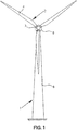
- a wind turbine 1, shown in Figure 1 comprises a nacelle 5, mounted atop a tower 6.
- a rotor 2, driving a DFIG wind turbine generator 10 (not shown) comprises rotor-blades 4 mounted on a hub 3.
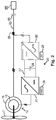
- a wind turbine generator 10, coupled to an electricity grid 50 is schematically illustrated in Fig. 2 .
- a generator-rotor 15 of the wind turbine generator is driven by a rotor 2.
- the rotor 15 is coupled to a converter 20.
- the generator and the converter together built the power-generating system of the wind turbine 1, shown in Fig. 1 .
- the machine-side inverter 25 of the converter 20 sets rotor-voltages and rotor-currents and thereby induces a magnetic flux in the generator-rotor 15, which may rotate faster than the rotor 2 or slower than rotor 2, depending on the current wind speed and the current desired power production of the wind turbine.
- the generator-side inverter 25 is, in turn, controlled by the generator-side inverter controller 26.
- the machine-side inverter 25 is connected to a grid-side inverter 30 by a DC link 27, comprising a capacitor 28 as an energy storage element.
- the grid-side inverter 30 is controlled by a grid-side converter controller 29.
- the generator-stator 16 in turn, is connected directly to the grid 50, via a series-compensated power transmission line 40.
- the power-output of the wind turbine is measured by a power/current-output measurement device 35.
- the series-compensation is given by a capacitor 45 connected in series to the power transmission line 40.
- the generator-rotor 15 induces fixed-frequency, e.g. 50 Hz, AC currents in the generator stator 16, to produce power (the currents in the rotor are set by the converter-system 20 such that the fixed-frequency current in the stator is reached).
- a wind park 100 including several wind turbines 1 and a point of common coupling 42 to an electricity grid 50 is shown in Fig. 3 .
- the wind turbines 1 of the wind park 100 are each connected to the point of common coupling 42, at which the wind park 100 is connected to the electricity-grid 50.
- the wind park feeds power to the electricity grid 50 via a series-compensated power transmission line 40.
- the series-compensation is achieved by connecting a capacitor 45 in series to the power transmission line 40.
- the inductivity 55 of the power-transmission line is schematically illustrated by inductance 55.
- An SSR-event occurring due to the series-compensation of power line 40, caused by the insertion of the capacitor 45, may spread through the point of common coupling 42 to the wind park 100, and thereby affect several wind turbines 1 of the wind park 100. This may cause massive damage to the wind turbines 1 of the wind park 100.
- the wind turbines 1 are protected by a protection method, capable of determining whether measured power-output values or current-output values are indicative of an SSR-event critical for further operation of the wind turbine and of shutting down the wind turbine if the result of the determination indeed points to such a critical SSR-event.
- the "integrated current-output-deviation” is referred to as “current-output deviation energy” or simply “deviation-energy”.
- the "accumulated integrated current-output-deviation value” is referred to as “accumulated current-output deviation-energy”.
- the "first integrated current-output-deviation threshold” is as the threshold for power-output deviation-energies also shortly referred to as “first energy threshold”. In this way also the “second integrated current-output deviation threshold” is shortly referred to as "second energy threshold”.
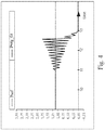
- FIG. 4 A diagram of undamped power-output oscillations around a reference power-output value over time is given by Fig. 4 . Approximately at 11s a power-output oscillation begins, induced by an SSR-event. From this moment on, the power-output oscillation is amplifying.
- the condition is reached at which the power-output values are determined to be indicative of an SSR-event critical for further operation of the wind turbine,.
- This condition is reached in this example, as an accumulated power-output deviation-energy (corresponding to an area under the curve) obtained over eight successive measurement cycles a 200ms has exceeded the given second energy threshold for that oscillation.
- the accumulated power-output deviation-energy value corresponds in this example to the area under the curve from 11s to approximately 12.6s.
- the wind turbine is shut down at approximately 13s to prevent damage to the wind turbine's components caused by the amplifying power oscillation induced by the SSR-event critical for further operation of the wind turbine.
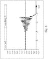
- FIG. 5 A diagram of damped power-output oscillations around a reference power-output value over time is given by Fig. 5 .
- the power-output oscillation occurs at approximately 10s and it is still present after 13s have passed.
- the oscillation is slightly dampened and no longer amplifying.
- An accumulated power-output deviation-energy value obtained over 8 successive measurement cycles a 200ms, for example measured from timestamps 10s to 11.6s, does not exceed the given second energy-threshold.
- the determination of that accumulated power-output deviation-energy value was triggered by a power-output exceeding the power-threshold at approximately timestamp 10s.
- a new accumulated power-output deviation-energy value is calculated using the power-outputs obtained in the measurement cycles from 10.2s to 11.8s (again the last eight measurement cycles) and is again compared to the second energy threshold.
- This accumulated power-output deviation-energy obtained in the cycles from 10.2s to 11.8s does not exceed the second-energy threshold either, and so on.
- the damped power-output oscillation shown in Fig. 5 , does not correspond to power-output values that are determined to be indicative of an SSR-event critical for further operation of the wind turbine by the method of protecting the DFIG wind turbine. Instead, the wind turbine is kept online during the SSR-event.
- FIG. 6 A diagram of undamped current-output oscillations around a reference current-output value for a DFIG-wind turbine injecting current into the grid at a voltage of 1kV, over time is given by Fig. 6 . Approximately at 11s a power-output oscillation begins, induced by an SSR-event. From this moment on, the current-output oscillation is amplifying.
- the condition is reached at which the current-output values are determined to be indicative of an SSR-event critical for further operation of the wind turbine.
- This condition is reached in this example, as an accumulated integrated current-output-deviation value (corresponding to an area under the curve) obtained over eight successive measurement cycles a 200ms has exceeded the given second integrated current-output-deviation threshold for that oscillation.
- the accumulated integrated current-output-deviation value corresponds in this example to the area under the curve from 11s to approximately 12.6s.
- the wind turbine is shut down at approximately 13s to prevent damage to the wind turbine's components caused by the amplifying current oscillation induced by the SSR-event critical for further operation of the wind turbine.
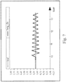
- FIG. 7 A diagram of damped current-output oscillations around a reference current-output value over time is given by Fig. 7 .
- the current-output oscillation occurs at approximately 10s and it is still present after 13s have passed.
- the oscillation is slightly dampened and no longer amplifying.
- An accumulated integrated current-output-deviation value obtained over 8 successive measurement cycles a 200ms, for example measured from timestamps 10s to 11.6s, does not exceed the given second integrated current-output-deviation threshold.
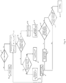
- FIG. 8 A schematic block-diagram, illustrating an exemplary method of protecting a wind turbine against an SSR-event acting on the wind turbine, wherein power-output deviation-energy values are used as the oscillation parameter is given by Fig. 8 .
- activity A1 an evaluation is made of whether a momentary power-output of the wind turbine exceeds a given power threshold. If the given power-threshold is not exceeded, normal wind turbine operation is continued in an activity A2 without any calculation of an oscillation parameter. However, if the current power exceeds the given power-threshold, the oscillation parameter is obtained for a current measurement cycle. In each measurement cycle a plurality of power-output values are obtained in a given time-span, such as 500ms or the like.
- the oscillation parameter indicative of the presence of an SSR-event critical for further operation of the wind turbine is an accumulated power-output deviation-energy value obtained based on power-output deviation-energy values.
- the power-output deviation-energy is calculated in activity A3 for a measurement cycle corresponding to a time window, by integrating the absolute value of the difference between (i) a reference output-power demanded by the electricity grid and (ii) power-output values, obtained within that time window, over time.
- an activity A4 it is tested whether the output-power deviation energy obtained in activity A3 exceeds a first energy-threshold. If the first energy-threshold is indeed exceeded, the exceeding power-output deviation-energy value of the measurement cycle is stored.
- the exceeding power-output deviation-energy values which were stored over the last ten measurement cycles, hence those power-output deviation-energy values obtained in the last ten measurement cycles that exceeded the first energy-threshold, are accumulated by adding up the deviation-energy values.
- the resulting accumulated power-output deviation-energy - serving asthe oscillation parameter in this example - is compared with a second energy-threshold in activity A7.
- a trend of the power-output deviation energy values e.g. "increasing”, "decreasing” or “substantially constant" is determined in activity A8. This determination in activity A8 is rather a background process and is not necessarily carried out after the accumulated power-output deviation-energy has been compared to the second energy-threshold.
- the accumulated power-output deviation-energy obtained in activity A6 does not exceed the second energy-threshold, the accumulated deviation-energy is reset in activity A13. It is set to zero so that in the next measurement cycle the accumulated power-output deviation energy values can be obtained for the ten measurement cycles preceding the next measurement cycle.
- the power-output deviation energy of the current cycle does not exceed the given first energy-threshold in activity A4, it is checked in activity A10 whether any deviation-energy of the last ten measurement cycles exceeded the first energy-threshold. If this is not the case, the stored power-output deviation-energy values are refreshed in activity A11, for example, by deleting stored deviation-energy values that were obtained before the last ten measurement cycles considered and replacing them with newly acquired power-output deviation-energy values that are stored as they exceed the first energy-threshold. After refreshing the stored power-output deviation-energy values, the method returns to activity A1, where the current power-output of the wind turbine is compared with the given first power-threshold.
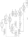
- FIG. 9 A schematic block-diagram, illustrating an exemplary method of protecting a wind turbine against an SSR-event acting on the wind turbine, wherein an accumulated integrated current-output-deviation energy value, is given by Fig. 9 .
- activity B1 an evaluation is made of whether a momentary current-output of the wind turbine exceeds a given current threshold. If the given current-threshold is not exceeded, normal wind turbine operation is continued in an activity B2 without any calculation of an oscillation parameter. However, if the momentary current exceeds the given current-threshold, the oscillation parameter is obtained for a current measurement cycle. In each measurement cycle a plurality of power-output values are obtained in a given time-span, such as 500ms or the like.
- the oscillation parameter indicative of the presence of an SSR-event critical for further operation of the wind turbine is an accumulated power-output deviation-energy value obtained based on current-output deviation-energy values.
- the current-output deviation-energy is calculated in activity B3 for a measurement cycle corresponding to a time window, by integrating the absolute value of the difference between (i) a reference current-output demanded by the electricity grid and (ii) current-output values, obtained within that time window, over time.
- FIG. 10 A schematic block diagram of another exemplary method of protecting a wind turbine converter system against a sub-synchronous resonance event acting on the wind turbine converter system is given by Fig. 10 .
- activity C1 a power-output value is measured in the course of a current measurement cycle.
- the power-output of the wind turbine is measured by a power-output measurement device, shown in Fig. 2 .
- the measured power-output value is compared with a power/current-output limit in activity C2. If the measured power-output value is greater than the power-output limit, a counter value is increased by one in activity C3. Thereby a count of power-output values that exceed the given power-output limit is performed.
- the counter value serves as the oscillation-parameter indicative of the presence of an SSR-event critical for further operation of the wind turbine. If the measured power-output is below the power-output limit, the measurement cycle continues in activity C9.
- the current value of the counter value is compared with a given admissible number of power-output values above the power-output limit in activity C4 that corresponds to the threshold to be exceeded by the value of the count to fulfill the at least one condition for determining the power-output values to be indicative of a critical SSR-event.
- the wind turbine When the counter value exceeds that admissible number the wind turbine is shut down. If the counter is, however, below that admissible number, and the measurement cycle has not finished, the measurement cycle simply continues in activity C8 and is continued by measuring a new power-output value. Otherwise, when the measurement cycle has finished, a new measurement cycle is started and the counter value is reset, e.g. set to zero again in activity C7.
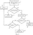
- FIG. 11 A schematic block diagram of another exemplary method of protecting a wind turbine converter system against a sub-synchronous resonance event acting on the wind turbine is given by Fig. 11 .
- This method corresponds to the method described in conjunction with Fig. 10 , however with the only difference that a current-output values are measured in the course of a measurement cycle in activity D1 and compared with a current-output limit D2 instead of power-output values being compared with a power-output limit.
- a counter value is increased by 1 in activity D3.
- This counter value serves as the oscillation-parameter in the method described in conjunction with Fig. 11 .
- the following activities D4 to D9 are analogous to the activities already described in conjunction with Fig. 10 .
Landscapes
- Engineering & Computer Science (AREA)
- Power Engineering (AREA)
- Life Sciences & Earth Sciences (AREA)
- Sustainable Development (AREA)
- Sustainable Energy (AREA)
- Chemical & Material Sciences (AREA)
- Combustion & Propulsion (AREA)
- Mechanical Engineering (AREA)
- General Engineering & Computer Science (AREA)
- Physics & Mathematics (AREA)
- General Physics & Mathematics (AREA)
- Artificial Intelligence (AREA)
- Computer Vision & Pattern Recognition (AREA)
- Evolutionary Computation (AREA)
- Medical Informatics (AREA)
- Software Systems (AREA)
- Health & Medical Sciences (AREA)
- Automation & Control Theory (AREA)
- Control Of Eletrric Generators (AREA)
- Wind Motors (AREA)
Claims (12)
- Verfahren zum Schützen einer Windkraftanlage (1) vor einem Ereignis einer untersynchronen Resonanz, SSR, das auf die Windkraftanlage (1) wirkt, wobei das Verfahren umfasst:Messen einer Vielzahl von Ausgangsleistungswerten oder Ausgangsstromwerten über einen gegebenen Zeitraum, der einem Messzyklus entspricht,Bestimmen, ob in dem mindestens einen Messzyklus gemessene Ausgangsleistungswerte oder Ausgangsstromwerte ein für den weiteren Betrieb der Windkraftanlage kritisches SSR-Ereignis angeben,wobei das Bestimmen ein Überwachen umfasst, ob mindestens ein Schwingungsparameter mindestens einen Schwingungsparameterschwellwert für mindestens einen Messzyklus überschreitet (A7, B7, C4, D4), wobei der Schwingungsparameter unter Verwendung der Ausgangsleistungswerte oder der Ausgangsstromwerte erhalten wird und für eine Ausgangsleistungsschwingung oder Ausgangsstromschwingung repräsentativ ist (A3-A6, B3-B6, C1-C3, D1-D3), wobei die Windkraftanlage als Reaktion darauf abgeschaltet wird, dass bestimmt wird, dass die gemessenen Ausgangsleistungswerte oder die gemessenen Ausgangsstromwerte ein SSR-Ereignis angeben, das für den weiteren Betrieb der Windkraftanlage kritisch ist (A9, B9, C5, D5),dadurch gekennzeichnet, dassdie Windkraftanlage eine Windkraftanlage mit einem doppelt gespeisten Induktionsgenerator, DFIG, (10) ist und der überwachte Schwingungsparameter basierend auf Differenzen zwischen (i) gemessenen Ausgangsleistungswerten oder Ausgangsstromwerten eines Messzyklus und (ii) einem Referenzausgangsleistungswert oder einem Referenzausgangsstromwert berechnet wird, wobei diese Differenzen im Laufe der Zeit integriert werden, um einen Ausgangsleistungsabweichungsenergiewert oder einen Wert einer integrierten Ausgangsstromabweichung eines Messzyklus zu erhalten (A3, B3),wobei der Ausgangsleistungsabweichungsenergiewert oder der Wert einer integrierten Ausgangsstromabweichung mit einem gegebenen Energieschwellwert oder einem gegebenen Schwellwert einer integrierten Stromabweichung verglichen wird und der Ausgangsleistungsabweichungsenergiewert oder der Wert einer integrierten Ausgangsstromabweichung des Messzyklus gespeichert wird, wenn der Ausgangsleistungsabweichungsenergiewert oder der Wert einer integrierten Ausgangsstromabweichung den gegebenen Energieschwellwert oder den Schwellwert einer integrierten Stromabweichung überschreitet (A5, B5),wobei ein akkumulierter Ausgangsleistungsabweichungsenergiewert oder ein akkumulierter integrierter Ausgangsstromabweichungswert unter Verwendung gespeicherter Ausgangsleistungsabweichungsenergiewerte oder gespeicherter integrierter Ausgangsstromabweichungswerte berechnet wird, die über eine gegebene Anzahl von aufeinanderfolgenden Messzyklen erhalten werden, wobei der akkumulierte Ausgangsleistungsabweichungsenergiewert oder der akkumulierte Wert einer integrierten Ausgangsstromabweichung dem Schwingungsparameter entspricht,wobei der Schwingungsparameter mit einem Schwingungsparameterschwellwert verglichen wird, wobei eine Bedingung für das Bestimmen des Vorliegens eines SSR-Ereignisses, das für den weiteren Betrieb der Windkraftanlage kritisch ist, darin besteht, dass mindestens ein Schwingungsparameter den Schwingungsparameterschwellwert überschreitet.
- Verfahren nach Anspruch 1, das Überwachen des mindestens einen Schwingungsparameters durch einen Ausgangsleistungswert oder einen Ausgangsstromwert ausgelöst wird, der einen jeweiligen gegebenen Leistungsschwellwert oder Stromschwellwert überschreitet (A1, B1, C1, D1).
- Verfahren nach Anspruch 1 oder 2, wobei der akkumulierte Ausgangsleistungsabweichungsenergiewert oder der akkumulierte Wert einer integrierten Ausgangsstromabweichung durch Addieren gespeicherter Ausgangsleistungsabweichungsenergiewerte oder gespeicherter Werte einer integrierten Ausgangsstromabweichung, die über eine gegebene Anzahl der Messzyklen erhalten werden, berechnet wird.
- Verfahren nach einem der Ansprüche 1 bis 3, wobei ein Trend der Ausgangsleistungsabweichungsenergiewerte oder der Werte einer integrierten Ausgangsstromabweichung über eine gegebene Anzahl von vorhergehenden Messzyklen bestimmt wird (A8, B8).
- Verfahren nach Anspruch 4, wobei die Ausgangsleistungsschwingung oder die Ausgangsstromschwingung, die als mit einem SSR-Ereignis, das für den weiteren Betrieb der Windkraftanlage kritisch ist, in Verbindung stehend bestimmt werden soll, als eine weitere Bedingung der Trend der Ausgangsleistungsabweichungsenergiewerte oder der Werte einer integrierten Ausgangsstromabweichung über die gegebene Anzahl von vorhergehenden Messzyklen zunehmen muss (A8, B8).
- Verfahren nach einem der Ansprüche 1 bis 5, wobei die gespeicherten Werte des Ausgangsleistungsabweichungsenergiewerts oder der integrierten Ausgangsstromabweichung aktualisiert werden, wenn die gegebene Anzahl der Messzyklen durchlaufen wurde, ohne dass Ausgangsleistungsabweichungsenergiewerte oder Werte einer integrierten Ausgangsstromabweichung den gegebenen Energieschwellwert oder den gegebenen Schwellwert einer integrierten Stromabweichung überschreiten (A10, A11, B10, B11).
- Windkraftanlage mit einem Windkraftanlageregler, wobei der Windkraftanlageregler zum Schützen der Windkraftanlage vor einem Ereignis einer untersynchronen Resonanz, SSR, die auf die Windkraftanlage wirkt, angeordnet ist, wobei der Windkraftanlageregler angeordnet ist zum:Empfangen einer Vielzahl von gemessenen Ausgangsleistungswerten oder Ausgangsstromwerten über einen gegebenen Zeitraum, der einem Messzyklus entspricht,Bestimmen, ob in dem mindestens einen Messzyklus gemessene Ausgangsleistungswerte oder Ausgangsstromwerte ein für den weiteren Betrieb der Windkraftanlage kritisches SSR-Ereignis angeben, wobei das Bestimmen ein Überwachen umfasst, ob mindestens ein Schwingungsparameter, der unter Verwendung der Ausgangsleistungswerte oder der Ausgangsstromwerte erhalten wird und für eine Ausgangsleistungsschwingung oder eine Ausgangsstromschwingung repräsentativ ist, mindestens einen Schwellwert für mindestens einen Messzyklus überschreitet, wobei eine Bedingung für das Bestimmen des Vorliegens eines SSR-Ereignisses, das für den weiteren Betrieb der Windkraftanlage kritisch ist, darin besteht, dass mindestens ein Schwingungsparameter den mindestens einen Schwellwert überschreitet,Abschalten der Windkraftanlage als Reaktion darauf, dass bestimmt wird, dass die gemessenen Ausgangsleistungswerte oder Ausgangsstromwerte ein SSR-Ereignis, das für den weiteren Betrieb der Windkraftanlage kritisch ist, angeben,dadurch gekennzeichnet, dass
die Windkraftanlage eine Windkraftanlage mit einem doppelt gespeisten Induktionsgenerator, DFIG, (10) ist und dass der Windkraftanlageregler weiter angeordnet ist zum:Berechnen des überwachten Schwingungsparameters basierend auf Differenzen zwischen (i) gemessenen Ausgangsleistungswerten oder Ausgangsstromwerten eines Messzyklus und (ii) einem Referenzausgangsleistungswert oder einem Referenzausgangsstromwert, wobei diese Differenzen im Laufe der Zeit integriert werden, um einen Ausgangsleistungsabweichungsenergiewert oder einen Wert einer integrierten Ausgangsstromabweichung eines Messzyklus zu erhalten (A3, B3),Vergleichen des Ausgangsleistungsabweichungsenergiewerts oder des Wert einer integrierten Ausgangsstromabweichung mit einem gegebenen Energieschwellwert oder einem gegebenen Schwellwert einer integrierten Stromabweichung und Speichern des Ausgangsleistungsabweichungsenergiewerts oder des Werts einer integrierten Ausgangsstromabweichung des Messzyklus, wenn der Ausgangsleistungsabweichungsenergiewert oder der Wert einer integrierten Ausgangsstromabweichung den gegebenen Energieschwellwert oder den Schwellwert einer integrierten Stromabweichung überschreitet (A5, B5),Berechnen eines Ausgangsleistungsabweichungsenergiewerts oder eines akkumulierten integrierten Ausgangsstromabweichungswerts unter Verwendung gespeicherter Ausgangsleistungsabweichungsenergiewerte oder gespeicherter Werte einer integrierten Ausgangsstromabweichung, die über eine gegebene Anzahl von aufeinanderfolgenden Messzyklen erhalten werden, wobei der akkumulierte Ausgangsleistungsabweichungsenergiewert oder der akkumulierte Wert einer integrierten Ausgangsstromabweichung dem Schwingungsparameter entspricht,Vergleichen des Schwingungsparameters mit einem Schwingungsparameterschwellwert, wobei eine Bedingung für das Bestimmen des Vorliegens eines SSR-Ereignisses, das für den weiteren Betrieb der Windkraftanlage kritisch ist, darin besteht, dass mindestens ein Schwingungsparameter den Schwingungsparameterschwellwert überschreitet. - Windkraftanlage nach Anspruch 7, wobei der Windkraftanlageregler weiter angeordnet ist zum:
Auslösen des Überwachens des mindestens einen Schwingungsparameters durch einen Ausgangsleistungswert oder einen Ausgangsstromwert, der einen jeweiligen gegebenen Leistungsschwellwert oder Stromschwellwert überschreitet (A1, B1, C1, D1). - Windkraftanlage nach Anspruch 7 oder 8, wobei der Windkraftanlageregler weiter angeordnet ist zum:
Berechnen des akkumulierten Ausgangsleistungsabweichungsenergiewerts oder des akkumulierten Werts einer integrierten Ausgangsstromabweichung durch Addieren gespeicherter Ausgangsleistungsabweichungsenergiewerte oder gespeicherter Werte einer integrierten Ausgangsstromabweichung, die über eine gegebene Anzahl der Messzyklen erhalten werden. - Windkraftanlage nach einem der Ansprüche 7 bis 9, wobei der Windkraftanlageregler weiter angeordnet ist zum:
Bestimmen eines Trends der Ausgangsleistungsabweichungsenergiewerte oder der Werte einer integrierten Ausgangsstromabweichung bestimmt ist über eine gegebene Anzahl von vorhergehenden Messzyklen (A8, B8). - Windkraftanlage nach Anspruch 10, wobei die Ausgangsleistungsschwingung oder die Ausgangsstromschwingung, die als mit einem SSR-Ereignis, das für den weiteren Betrieb der Windkraftanlage kritisch ist, in Verbindung stehend bestimmt werden soll, als eine weitere Bedingung der Trend der Ausgangsleistungsabweichungsenergiewerte oder der Werte einer integrierten Ausgangsstromabweichung über die gegebene Anzahl von vorhergehenden Messzyklen zunehmen muss (A8, B8).
- Windkraftanlage nach einem der Ansprüche 7 bis 11, wobei der Windkraftanlageregler weiter angeordnet ist zum:
Aktualisieren der gespeicherten Werte des Ausgangsleistungsabweichungsenergiewerts oder der integrierten Ausgangsstromabweichung aktualisiert sind, wenn die gegebene Anzahl der Messzyklen durchlaufen wurde, ohne dass Ausgangsleistungsabweichungsenergiewerte oder Werte einer integrierten Ausgangsstromabweichung den gegebenen Energieschwellwert oder den gegebenen Schwellwert einer integrierten Stromabweichung überschreiten (A10, A11, B10, B11).
Applications Claiming Priority (2)
| Application Number | Priority Date | Filing Date | Title |
|---|---|---|---|
| DKPA201570403 | 2015-06-29 | ||
| PCT/DK2016/050188 WO2017000946A1 (en) | 2015-06-29 | 2016-06-16 | Method of operating a dfig wind turbine under ssr |
Publications (2)
| Publication Number | Publication Date |
|---|---|
| EP3314710A1 EP3314710A1 (de) | 2018-05-02 |
| EP3314710B1 true EP3314710B1 (de) | 2021-08-04 |
Family
ID=56194194
Family Applications (1)
| Application Number | Title | Priority Date | Filing Date |
|---|---|---|---|
| EP16731502.7A Active EP3314710B1 (de) | 2015-06-29 | 2016-06-16 | Verfahren zum betreiben einer dfig-windturbine unter ssr |
Country Status (5)
| Country | Link |
|---|---|
| US (1) | US10544778B2 (de) |
| EP (1) | EP3314710B1 (de) |
| CN (1) | CN107710538B (de) |
| ES (1) | ES2882666T3 (de) |
| WO (1) | WO2017000946A1 (de) |
Families Citing this family (4)
| Publication number | Priority date | Publication date | Assignee | Title |
|---|---|---|---|---|
| WO2018121821A1 (en) * | 2016-12-27 | 2018-07-05 | Vestas Wind Systems A/S | Control system for modular multilevel converter |
| EP3633847B1 (de) | 2018-10-05 | 2021-12-01 | Vestas Wind Systems A/S | Verfahren zur handhabung subsynchroner resonanzen |
| CN112260242B (zh) * | 2020-09-18 | 2022-09-13 | 西安理工大学 | 一种含dfig配电网线路纵联保护方法 |
| CN112886800A (zh) * | 2020-12-31 | 2021-06-01 | 江苏东方四通科技股份有限公司 | 一种具有自动限流保护功能的功率控制器 |
Family Cites Families (22)
| Publication number | Priority date | Publication date | Assignee | Title |
|---|---|---|---|---|
| DE2205793C3 (de) | 1972-02-08 | 1974-09-12 | Bodenseewerk Perkin-Elmer & Co Gmbh, 7770 Ueberlingen | Schaltungsanordnung zum Abgleich der Nullinie |
| US4451777A (en) | 1981-09-10 | 1984-05-29 | Westinghouse Electric Corp. | Static VAR generation for transmission line compensation |
| US4757432A (en) * | 1981-11-17 | 1988-07-12 | Hughes Aircraft Company | Series resonant inverter with integrating feedback control loop |
| US4607217A (en) | 1983-09-28 | 1986-08-19 | Southern California Edison Company, Inc. | Subsynchronous resonance detection |
| DE3631167A1 (de) | 1986-09-11 | 1988-03-24 | Siemens Ag | Verfahren zum erzeugen eines ausloesesignals in abhaengigkeit von der groesse und der dauer eines ueberstromes |
| JPH1051943A (ja) | 1996-08-01 | 1998-02-20 | Fuji Photo Film Co Ltd | 電力供給装置 |
| US6774614B2 (en) | 2002-02-27 | 2004-08-10 | General Electric Company | Method and apparatus for detecting current |
| DE10238831A1 (de) * | 2002-08-23 | 2004-03-11 | Siemens Ag | Verfahren und Vorrichtung zur Prozessoptimierung |
| CA2748459C (en) * | 2009-01-30 | 2014-06-03 | Dewind Co. | Adaptive voltage control for wind turbines |
| US9478987B2 (en) * | 2009-11-10 | 2016-10-25 | Siemens Aktiengesellschaft | Power oscillation damping employing a full or partial conversion wind turbine |
| EP2357483B1 (de) | 2010-02-17 | 2013-06-26 | ABB Research Ltd. | Verfahren zur Detektion von subsynchroner Resonanz |
| CA2792499A1 (en) * | 2010-03-11 | 2011-09-15 | Siemens Aktiengesellschaft | Method and system for damping subsynchronous resonant oscillations in a power system using a wind turbine |
| CA2753666A1 (en) * | 2010-09-29 | 2012-03-29 | Erlphase Power Technologies Limited | Method and apparatus for sub-harmonic protection |
| US10110010B2 (en) * | 2011-04-15 | 2018-10-23 | Deka Products Limited Partnership | Modular power conversion system |
| US8558405B2 (en) * | 2011-05-26 | 2013-10-15 | Siemens Aktiengesellschaft | Method and system for operating and controlling a wind turbine to prevent excitation of subsynchronous oscillations within the wind turbine |
| TWI438602B (zh) * | 2011-12-02 | 2014-05-21 | Ind Tech Res Inst | 最大功率點追蹤控制器、最大功率點追蹤系統和最大功率點追蹤方法 |
| WO2014038966A1 (en) * | 2012-09-06 | 2014-03-13 | Auckland Uniservices Limited | Local demand side power management for electric utility networks |
| CN104350661A (zh) | 2013-02-01 | 2015-02-11 | Abb技术有限公司 | 缓解电力传输系统中次同步谐振的方法和装置 |
| US20140365021A1 (en) * | 2013-06-05 | 2014-12-11 | Kyle Workman | System and Method of Monitoring an Irrigation System |
| US9768686B2 (en) * | 2014-12-31 | 2017-09-19 | Dialog Semiconductor Inc. | Feedback scheme for non-isolated power supply |
| WO2016124797A1 (es) * | 2015-02-02 | 2016-08-11 | Ingeteam Power Technology, S.A. | Método de control para un sistema que comprende un convertidor de frecuencia conectado a una red eléctrica |
| US9941828B2 (en) * | 2015-02-27 | 2018-04-10 | General Electric Company | System and method for stabilizing sub-synchronous interaction of a wind turbine generator |
-
2016
- 2016-06-16 EP EP16731502.7A patent/EP3314710B1/de active Active
- 2016-06-16 US US15/573,931 patent/US10544778B2/en active Active
- 2016-06-16 WO PCT/DK2016/050188 patent/WO2017000946A1/en not_active Ceased
- 2016-06-16 ES ES16731502T patent/ES2882666T3/es active Active
- 2016-06-16 CN CN201680039099.3A patent/CN107710538B/zh active Active
Also Published As
| Publication number | Publication date |
|---|---|
| ES2882666T3 (es) | 2021-12-02 |
| EP3314710A1 (de) | 2018-05-02 |
| CN107710538B (zh) | 2019-10-25 |
| US20180291876A1 (en) | 2018-10-11 |
| US10544778B2 (en) | 2020-01-28 |
| WO2017000946A1 (en) | 2017-01-05 |
| CN107710538A (zh) | 2018-02-16 |
Similar Documents
| Publication | Publication Date | Title |
|---|---|---|
| Xie et al. | Characteristic analysis of subsynchronous resonance in practical wind farms connected to series-compensated transmissions | |
| US7987067B2 (en) | Method and apparatus for optimizing wind turbine operation | |
| US8509958B2 (en) | Power limiter system | |
| Wu et al. | Towards an assessment of power system frequency support from wind plant—Modeling aggregate inertial response | |
| EP2311164B1 (de) | Verfahren und system zum steuern einer windenergieanlage, die eine anzahl von windturbinengeneratoren umfasst | |
| EP2688172B1 (de) | Verfahren und Vorrichtung zur adaptiven Steuerung von Windparkturbinen | |
| US20160245259A1 (en) | A method for controlling a wind power plant and a wind power plant | |
| US20130138257A1 (en) | System for operating an electric power system and method of operating the same | |
| CN108204336B (zh) | 风力发电机组的停机方法和装置、存储介质及计算装置 | |
| Gao et al. | Identifying and ranking sources of SSR based on the concept of subsynchronous power | |
| JP2014148983A (ja) | 風力発電システム | |
| US10544778B2 (en) | Method of operating a DFIG wind turbine under SSR | |
| EP2375059A2 (de) | Torsionsschutzsystem und -verfahren für eine Windturbine | |
| US11411519B2 (en) | Method for handling sub-synchronous resonances | |
| EP2573894A2 (de) | Verfahren und Systeme für den Betrieb eines Stromerzeugungs- und -versorgungssystems | |
| Li et al. | Mitigating SSO in an actual DFIG-MTDC system: Field implementation and tests | |
| CN102820665A (zh) | 一种快速识别风电并网系统发生次同步震荡的方法 | |
| CN115189368A (zh) | 电网宽频振荡抑制方法、系统、计算机设备及存储介质 | |
| Peterson et al. | Application of a subharmonic protection relay | |
| Amin et al. | improvement integration of Zafrana Egypt wind farm connected to the unified power grid | |
| CN119965953B (zh) | 电网惯量在线评估方法、系统、计算机设备及存储介质 | |
| Meshram et al. | Subsynchronous Oscillations Identification in Series-Compensated DFIG-Based Wind Farm Using Machine Learning Algorithms: A Comprehensive Review | |
| Xu et al. | Control-Level Sub-Synchronous Oscillation Source Identification for IBRs-Dominated Power Systems Based on Initial Instantaneous Power Characteristics | |
| Zhao | The research of zero voltage ride through strategy of DFIG | |
| Meisingset et al. | Field tests and modelling of a wind farm with doubly fed induction generators |
Legal Events
| Date | Code | Title | Description |
|---|---|---|---|
| STAA | Information on the status of an ep patent application or granted ep patent |
Free format text: STATUS: THE INTERNATIONAL PUBLICATION HAS BEEN MADE |
|
| PUAI | Public reference made under article 153(3) epc to a published international application that has entered the european phase |
Free format text: ORIGINAL CODE: 0009012 |
|
| STAA | Information on the status of an ep patent application or granted ep patent |
Free format text: STATUS: REQUEST FOR EXAMINATION WAS MADE |
|
| 17P | Request for examination filed |
Effective date: 20171122 |
|
| AK | Designated contracting states |
Kind code of ref document: A1 Designated state(s): AL AT BE BG CH CY CZ DE DK EE ES FI FR GB GR HR HU IE IS IT LI LT LU LV MC MK MT NL NO PL PT RO RS SE SI SK SM TR |
|
| AX | Request for extension of the european patent |
Extension state: BA ME |
|
| RIN1 | Information on inventor provided before grant (corrected) |
Inventor name: GUPTA, MANOJ Inventor name: ZHOU, YI Inventor name: ANDERSEN, GERT KARMISHOLT Inventor name: GANEPOLA, VAJIRA SUMINDA Inventor name: BIRIS, CIPRIAN Inventor name: COVA ACOSTA, MIGUEL ANGEL |
|
| DAV | Request for validation of the european patent (deleted) | ||
| DAX | Request for extension of the european patent (deleted) | ||
| GRAJ | Information related to disapproval of communication of intention to grant by the applicant or resumption of examination proceedings by the epo deleted |
Free format text: ORIGINAL CODE: EPIDOSDIGR1 |
|
| GRAP | Despatch of communication of intention to grant a patent |
Free format text: ORIGINAL CODE: EPIDOSNIGR1 |
|
| GRAP | Despatch of communication of intention to grant a patent |
Free format text: ORIGINAL CODE: EPIDOSNIGR1 |
|
| STAA | Information on the status of an ep patent application or granted ep patent |
Free format text: STATUS: GRANT OF PATENT IS INTENDED |
|
| INTG | Intention to grant announced |
Effective date: 20210205 |
|
| INTG | Intention to grant announced |
Effective date: 20210212 |
|
| GRAS | Grant fee paid |
Free format text: ORIGINAL CODE: EPIDOSNIGR3 |
|
| GRAA | (expected) grant |
Free format text: ORIGINAL CODE: 0009210 |
|
| STAA | Information on the status of an ep patent application or granted ep patent |
Free format text: STATUS: THE PATENT HAS BEEN GRANTED |
|
| AK | Designated contracting states |
Kind code of ref document: B1 Designated state(s): AL AT BE BG CH CY CZ DE DK EE ES FI FR GB GR HR HU IE IS IT LI LT LU LV MC MK MT NL NO PL PT RO RS SE SI SK SM TR |
|
| REG | Reference to a national code |
Ref country code: GB Ref legal event code: FG4D |
|
| REG | Reference to a national code |
Ref country code: AT Ref legal event code: REF Ref document number: 1417983 Country of ref document: AT Kind code of ref document: T Effective date: 20210815 |
|
| REG | Reference to a national code |
Ref country code: CH Ref legal event code: EP |
|
| REG | Reference to a national code |
Ref country code: DE Ref legal event code: R096 Ref document number: 602016061571 Country of ref document: DE |
|
| REG | Reference to a national code |
Ref country code: IE Ref legal event code: FG4D |
|
| REG | Reference to a national code |
Ref country code: LT Ref legal event code: MG9D |
|
| REG | Reference to a national code |
Ref country code: ES Ref legal event code: FG2A Ref document number: 2882666 Country of ref document: ES Kind code of ref document: T3 Effective date: 20211202 |
|
| REG | Reference to a national code |
Ref country code: NL Ref legal event code: MP Effective date: 20210804 |
|
| REG | Reference to a national code |
Ref country code: AT Ref legal event code: MK05 Ref document number: 1417983 Country of ref document: AT Kind code of ref document: T Effective date: 20210804 |
|
| PG25 | Lapsed in a contracting state [announced via postgrant information from national office to epo] |
Ref country code: RS Free format text: LAPSE BECAUSE OF FAILURE TO SUBMIT A TRANSLATION OF THE DESCRIPTION OR TO PAY THE FEE WITHIN THE PRESCRIBED TIME-LIMIT Effective date: 20210804 Ref country code: SE Free format text: LAPSE BECAUSE OF FAILURE TO SUBMIT A TRANSLATION OF THE DESCRIPTION OR TO PAY THE FEE WITHIN THE PRESCRIBED TIME-LIMIT Effective date: 20210804 Ref country code: AT Free format text: LAPSE BECAUSE OF FAILURE TO SUBMIT A TRANSLATION OF THE DESCRIPTION OR TO PAY THE FEE WITHIN THE PRESCRIBED TIME-LIMIT Effective date: 20210804 Ref country code: BG Free format text: LAPSE BECAUSE OF FAILURE TO SUBMIT A TRANSLATION OF THE DESCRIPTION OR TO PAY THE FEE WITHIN THE PRESCRIBED TIME-LIMIT Effective date: 20211104 Ref country code: LT Free format text: LAPSE BECAUSE OF FAILURE TO SUBMIT A TRANSLATION OF THE DESCRIPTION OR TO PAY THE FEE WITHIN THE PRESCRIBED TIME-LIMIT Effective date: 20210804 Ref country code: NO Free format text: LAPSE BECAUSE OF FAILURE TO SUBMIT A TRANSLATION OF THE DESCRIPTION OR TO PAY THE FEE WITHIN THE PRESCRIBED TIME-LIMIT Effective date: 20211104 Ref country code: PT Free format text: LAPSE BECAUSE OF FAILURE TO SUBMIT A TRANSLATION OF THE DESCRIPTION OR TO PAY THE FEE WITHIN THE PRESCRIBED TIME-LIMIT Effective date: 20211206 Ref country code: FI Free format text: LAPSE BECAUSE OF FAILURE TO SUBMIT A TRANSLATION OF THE DESCRIPTION OR TO PAY THE FEE WITHIN THE PRESCRIBED TIME-LIMIT Effective date: 20210804 Ref country code: HR Free format text: LAPSE BECAUSE OF FAILURE TO SUBMIT A TRANSLATION OF THE DESCRIPTION OR TO PAY THE FEE WITHIN THE PRESCRIBED TIME-LIMIT Effective date: 20210804 |
|
| PG25 | Lapsed in a contracting state [announced via postgrant information from national office to epo] |
Ref country code: PL Free format text: LAPSE BECAUSE OF FAILURE TO SUBMIT A TRANSLATION OF THE DESCRIPTION OR TO PAY THE FEE WITHIN THE PRESCRIBED TIME-LIMIT Effective date: 20210804 Ref country code: LV Free format text: LAPSE BECAUSE OF FAILURE TO SUBMIT A TRANSLATION OF THE DESCRIPTION OR TO PAY THE FEE WITHIN THE PRESCRIBED TIME-LIMIT Effective date: 20210804 Ref country code: GR Free format text: LAPSE BECAUSE OF FAILURE TO SUBMIT A TRANSLATION OF THE DESCRIPTION OR TO PAY THE FEE WITHIN THE PRESCRIBED TIME-LIMIT Effective date: 20211105 |
|
| PG25 | Lapsed in a contracting state [announced via postgrant information from national office to epo] |
Ref country code: NL Free format text: LAPSE BECAUSE OF FAILURE TO SUBMIT A TRANSLATION OF THE DESCRIPTION OR TO PAY THE FEE WITHIN THE PRESCRIBED TIME-LIMIT Effective date: 20210804 |
|
| PG25 | Lapsed in a contracting state [announced via postgrant information from national office to epo] |
Ref country code: DK Free format text: LAPSE BECAUSE OF FAILURE TO SUBMIT A TRANSLATION OF THE DESCRIPTION OR TO PAY THE FEE WITHIN THE PRESCRIBED TIME-LIMIT Effective date: 20210804 |
|
| REG | Reference to a national code |
Ref country code: DE Ref legal event code: R097 Ref document number: 602016061571 Country of ref document: DE |
|
| PG25 | Lapsed in a contracting state [announced via postgrant information from national office to epo] |
Ref country code: SM Free format text: LAPSE BECAUSE OF FAILURE TO SUBMIT A TRANSLATION OF THE DESCRIPTION OR TO PAY THE FEE WITHIN THE PRESCRIBED TIME-LIMIT Effective date: 20210804 Ref country code: SK Free format text: LAPSE BECAUSE OF FAILURE TO SUBMIT A TRANSLATION OF THE DESCRIPTION OR TO PAY THE FEE WITHIN THE PRESCRIBED TIME-LIMIT Effective date: 20210804 Ref country code: RO Free format text: LAPSE BECAUSE OF FAILURE TO SUBMIT A TRANSLATION OF THE DESCRIPTION OR TO PAY THE FEE WITHIN THE PRESCRIBED TIME-LIMIT Effective date: 20210804 Ref country code: EE Free format text: LAPSE BECAUSE OF FAILURE TO SUBMIT A TRANSLATION OF THE DESCRIPTION OR TO PAY THE FEE WITHIN THE PRESCRIBED TIME-LIMIT Effective date: 20210804 Ref country code: CZ Free format text: LAPSE BECAUSE OF FAILURE TO SUBMIT A TRANSLATION OF THE DESCRIPTION OR TO PAY THE FEE WITHIN THE PRESCRIBED TIME-LIMIT Effective date: 20210804 Ref country code: AL Free format text: LAPSE BECAUSE OF FAILURE TO SUBMIT A TRANSLATION OF THE DESCRIPTION OR TO PAY THE FEE WITHIN THE PRESCRIBED TIME-LIMIT Effective date: 20210804 |
|
| PLBE | No opposition filed within time limit |
Free format text: ORIGINAL CODE: 0009261 |
|
| STAA | Information on the status of an ep patent application or granted ep patent |
Free format text: STATUS: NO OPPOSITION FILED WITHIN TIME LIMIT |
|
| 26N | No opposition filed |
Effective date: 20220506 |
|
| PG25 | Lapsed in a contracting state [announced via postgrant information from national office to epo] |
Ref country code: IT Free format text: LAPSE BECAUSE OF FAILURE TO SUBMIT A TRANSLATION OF THE DESCRIPTION OR TO PAY THE FEE WITHIN THE PRESCRIBED TIME-LIMIT Effective date: 20210804 |
|
| PG25 | Lapsed in a contracting state [announced via postgrant information from national office to epo] |
Ref country code: SI Free format text: LAPSE BECAUSE OF FAILURE TO SUBMIT A TRANSLATION OF THE DESCRIPTION OR TO PAY THE FEE WITHIN THE PRESCRIBED TIME-LIMIT Effective date: 20210804 |
|
| PG25 | Lapsed in a contracting state [announced via postgrant information from national office to epo] |
Ref country code: MC Free format text: LAPSE BECAUSE OF FAILURE TO SUBMIT A TRANSLATION OF THE DESCRIPTION OR TO PAY THE FEE WITHIN THE PRESCRIBED TIME-LIMIT Effective date: 20210804 |
|
| REG | Reference to a national code |
Ref country code: CH Ref legal event code: PL |
|
| REG | Reference to a national code |
Ref country code: BE Ref legal event code: MM Effective date: 20220630 |
|
| PG25 | Lapsed in a contracting state [announced via postgrant information from national office to epo] |
Ref country code: LU Free format text: LAPSE BECAUSE OF NON-PAYMENT OF DUE FEES Effective date: 20220616 Ref country code: LI Free format text: LAPSE BECAUSE OF NON-PAYMENT OF DUE FEES Effective date: 20220630 Ref country code: IE Free format text: LAPSE BECAUSE OF NON-PAYMENT OF DUE FEES Effective date: 20220616 Ref country code: CH Free format text: LAPSE BECAUSE OF NON-PAYMENT OF DUE FEES Effective date: 20220630 |
|
| PG25 | Lapsed in a contracting state [announced via postgrant information from national office to epo] |
Ref country code: BE Free format text: LAPSE BECAUSE OF NON-PAYMENT OF DUE FEES Effective date: 20220630 |
|
| P01 | Opt-out of the competence of the unified patent court (upc) registered |
Effective date: 20230521 |
|
| PG25 | Lapsed in a contracting state [announced via postgrant information from national office to epo] |
Ref country code: HU Free format text: LAPSE BECAUSE OF FAILURE TO SUBMIT A TRANSLATION OF THE DESCRIPTION OR TO PAY THE FEE WITHIN THE PRESCRIBED TIME-LIMIT; INVALID AB INITIO Effective date: 20160616 |
|
| PG25 | Lapsed in a contracting state [announced via postgrant information from national office to epo] |
Ref country code: MK Free format text: LAPSE BECAUSE OF FAILURE TO SUBMIT A TRANSLATION OF THE DESCRIPTION OR TO PAY THE FEE WITHIN THE PRESCRIBED TIME-LIMIT Effective date: 20210804 Ref country code: CY Free format text: LAPSE BECAUSE OF FAILURE TO SUBMIT A TRANSLATION OF THE DESCRIPTION OR TO PAY THE FEE WITHIN THE PRESCRIBED TIME-LIMIT Effective date: 20210804 |
|
| PG25 | Lapsed in a contracting state [announced via postgrant information from national office to epo] |
Ref country code: MT Free format text: LAPSE BECAUSE OF FAILURE TO SUBMIT A TRANSLATION OF THE DESCRIPTION OR TO PAY THE FEE WITHIN THE PRESCRIBED TIME-LIMIT Effective date: 20210804 |
|
| PGFP | Annual fee paid to national office [announced via postgrant information from national office to epo] |
Ref country code: ES Payment date: 20250710 Year of fee payment: 10 |
|
| PG25 | Lapsed in a contracting state [announced via postgrant information from national office to epo] |
Ref country code: TR Free format text: LAPSE BECAUSE OF FAILURE TO SUBMIT A TRANSLATION OF THE DESCRIPTION OR TO PAY THE FEE WITHIN THE PRESCRIBED TIME-LIMIT Effective date: 20210804 |
|
| PGFP | Annual fee paid to national office [announced via postgrant information from national office to epo] |
Ref country code: GB Payment date: 20260622 Year of fee payment: 11 |
|
| PGFP | Annual fee paid to national office [announced via postgrant information from national office to epo] |
Ref country code: DE Payment date: 20260623 Year of fee payment: 11 |
|
| PGFP | Annual fee paid to national office [announced via postgrant information from national office to epo] |
Ref country code: FR Payment date: 20260622 Year of fee payment: 11 |