EP3314340B1 - Steuerungskontextualisierung und schlussfolgerung über die steuerung - Google Patents
Steuerungskontextualisierung und schlussfolgerung über die steuerung Download PDFInfo
- Publication number
- EP3314340B1 EP3314340B1 EP15738532.9A EP15738532A EP3314340B1 EP 3314340 B1 EP3314340 B1 EP 3314340B1 EP 15738532 A EP15738532 A EP 15738532A EP 3314340 B1 EP3314340 B1 EP 3314340B1
- Authority
- EP
- European Patent Office
- Prior art keywords
- control
- control program
- program
- monitoring
- data
- Prior art date
- Legal status (The legal status is an assumption and is not a legal conclusion. Google has not performed a legal analysis and makes no representation as to the accuracy of the status listed.)
- Active
Links
- 238000000034 method Methods 0.000 claims description 61
- 230000006870 function Effects 0.000 claims description 32
- 238000012544 monitoring process Methods 0.000 claims description 29
- 230000008569 process Effects 0.000 claims description 24
- 238000011161 development Methods 0.000 claims description 16
- 238000003860 storage Methods 0.000 claims description 9
- 238000004519 manufacturing process Methods 0.000 description 12
- 125000004122 cyclic group Chemical group 0.000 description 6
- 238000010586 diagram Methods 0.000 description 6
- 230000004044 response Effects 0.000 description 6
- 238000004458 analytical method Methods 0.000 description 5
- 238000004891 communication Methods 0.000 description 4
- 230000003993 interaction Effects 0.000 description 4
- 238000005457 optimization Methods 0.000 description 4
- 230000008520 organization Effects 0.000 description 4
- 238000012545 processing Methods 0.000 description 4
- 230000001133 acceleration Effects 0.000 description 3
- 230000008901 benefit Effects 0.000 description 3
- 230000005540 biological transmission Effects 0.000 description 3
- 230000000694 effects Effects 0.000 description 3
- 230000007246 mechanism Effects 0.000 description 3
- 230000010355 oscillation Effects 0.000 description 3
- 230000005856 abnormality Effects 0.000 description 2
- 238000012517 data analytics Methods 0.000 description 2
- 238000013144 data compression Methods 0.000 description 2
- 238000013461 design Methods 0.000 description 2
- 238000005516 engineering process Methods 0.000 description 2
- 238000001914 filtration Methods 0.000 description 2
- 238000005259 measurement Methods 0.000 description 2
- 238000011002 quantification Methods 0.000 description 2
- RYGMFSIKBFXOCR-UHFFFAOYSA-N Copper Chemical compound [Cu] RYGMFSIKBFXOCR-UHFFFAOYSA-N 0.000 description 1
- 238000013473 artificial intelligence Methods 0.000 description 1
- 230000006399 behavior Effects 0.000 description 1
- 230000001364 causal effect Effects 0.000 description 1
- 238000007906 compression Methods 0.000 description 1
- 230000006835 compression Effects 0.000 description 1
- 230000001143 conditioned effect Effects 0.000 description 1
- 230000003750 conditioning effect Effects 0.000 description 1
- 238000007405 data analysis Methods 0.000 description 1
- 238000013500 data storage Methods 0.000 description 1
- 230000007547 defect Effects 0.000 description 1
- 230000001419 dependent effect Effects 0.000 description 1
- 238000001514 detection method Methods 0.000 description 1
- 230000002708 enhancing effect Effects 0.000 description 1
- 230000007613 environmental effect Effects 0.000 description 1
- 239000000835 fiber Substances 0.000 description 1
- 230000003116 impacting effect Effects 0.000 description 1
- 230000010365 information processing Effects 0.000 description 1
- 230000000977 initiatory effect Effects 0.000 description 1
- 238000007689 inspection Methods 0.000 description 1
- 230000010354 integration Effects 0.000 description 1
- 230000002452 interceptive effect Effects 0.000 description 1
- 238000007726 management method Methods 0.000 description 1
- 238000013507 mapping Methods 0.000 description 1
- 238000012986 modification Methods 0.000 description 1
- 230000004048 modification Effects 0.000 description 1
- 230000003287 optical effect Effects 0.000 description 1
- 238000005192 partition Methods 0.000 description 1
- 238000012805 post-processing Methods 0.000 description 1
- 238000004540 process dynamic Methods 0.000 description 1
- 230000008439 repair process Effects 0.000 description 1
- 238000005070 sampling Methods 0.000 description 1
- 230000001953 sensory effect Effects 0.000 description 1
- 239000007787 solid Substances 0.000 description 1
- 238000012360 testing method Methods 0.000 description 1
- 238000012800 visualization Methods 0.000 description 1
Images


Classifications
-
- G—PHYSICS
- G05—CONTROLLING; REGULATING
- G05B—CONTROL OR REGULATING SYSTEMS IN GENERAL; FUNCTIONAL ELEMENTS OF SUCH SYSTEMS; MONITORING OR TESTING ARRANGEMENTS FOR SUCH SYSTEMS OR ELEMENTS
- G05B19/00—Programme-control systems
- G05B19/02—Programme-control systems electric
- G05B19/04—Programme control other than numerical control, i.e. in sequence controllers or logic controllers
- G05B19/05—Programmable logic controllers, e.g. simulating logic interconnections of signals according to ladder diagrams or function charts
- G05B19/058—Safety, monitoring
-
- G—PHYSICS
- G05—CONTROLLING; REGULATING
- G05B—CONTROL OR REGULATING SYSTEMS IN GENERAL; FUNCTIONAL ELEMENTS OF SUCH SYSTEMS; MONITORING OR TESTING ARRANGEMENTS FOR SUCH SYSTEMS OR ELEMENTS
- G05B19/00—Programme-control systems
- G05B19/02—Programme-control systems electric
- G05B19/04—Programme control other than numerical control, i.e. in sequence controllers or logic controllers
- G05B19/05—Programmable logic controllers, e.g. simulating logic interconnections of signals according to ladder diagrams or function charts
-
- G—PHYSICS
- G05—CONTROLLING; REGULATING
- G05B—CONTROL OR REGULATING SYSTEMS IN GENERAL; FUNCTIONAL ELEMENTS OF SUCH SYSTEMS; MONITORING OR TESTING ARRANGEMENTS FOR SUCH SYSTEMS OR ELEMENTS
- G05B2219/00—Program-control systems
- G05B2219/10—Plc systems
- G05B2219/14—Plc safety
- G05B2219/14006—Safety, monitoring in general
-
- G—PHYSICS
- G05—CONTROLLING; REGULATING
- G05B—CONTROL OR REGULATING SYSTEMS IN GENERAL; FUNCTIONAL ELEMENTS OF SUCH SYSTEMS; MONITORING OR TESTING ARRANGEMENTS FOR SUCH SYSTEMS OR ELEMENTS
- G05B2219/00—Program-control systems
- G05B2219/10—Plc systems
- G05B2219/14—Plc safety
- G05B2219/14083—Derive diagnostic program from model needed for sequence program
Definitions
- the present invention relates generally to the use of a programmable logic controller which includes functionality for control contextualization and reasoning about control operations.
- the disclosed technology may be applied to, for example, various automated production environments where programmable controllers are used.
- a programmable logic controller is a specialized computer control system configured to execute software which continuously gathers data on the state of input devices to control the state of output devices.
- a PLC typically includes three major components: a processor (which may include volatile memory), volatile memory comprising an application program, and one or more input/output (I/O) ports for connecting to other devices in the automation system. PLCs are utilized in various industrial settings to control automation systems.
- US 2015/0268655 discloses a method for verifying an interlock function of a PLC control program using control intermediate model, which is simplified to analyze only variables causing erroneous situations using a symbolic model verifier (SMV).
- SMV symbolic model verifier
- EP 1452969 discloses a method for checking presence or absence of abnormality in control model or control program by checking correspondence between written control model and required control program via testing apparatus and a testing program, where the error(s) in the control model is corrected by manually rewriting the control model.
- a method of operating an intelligent logic controller is provided as defined in claim 1.
- the method further comprises identifying one or more faults in the control program using the control model.
- the method includes debugging the control program using the control model.
- the method includes adjusting one or more algorithms included in the control program based on the control model.
- control model is automatically extracted from program code in an engineering development environment.
- the control model may include for example, structural information related to program functions used by the control program and control flow information related to the program functions. Additionally (or alternatively), the control model may include dependency information relating process variables and variables used by the control program. Also, in some embodiments, the control model further includes knowledge performance indicator (KPI) definitions related to the control program.
- KPI knowledge performance indicator
- a programmable logic controller is provided as defined in claim 10.
- Systems, methods, and apparatuses are described herein which relate generally to an Intelligent PLC (described below) which includes functionality for control contextualization and reasoning about control. More specifically, the various embodiments described herein describe the development, implementation, and use of a control model that represents information about the control programs that run on the controlling PLCs and about the interfaces to embedded controllers that operate devices.
- the control model supports the operational understanding of the system and data analysis, using semantic annotation of embedded control programs.
- This control model may include, for example, knowledge about the structure of control program functions, the control flow of the program blocks, dependencies of process variables and control variables and Key Performance Indicator (KPI) definitions about control quality and monitoring rules.
- KPI Key Performance Indicator
- control model is available and accessible on the controller device.
- the control model is explicitly represented by a formal knowledge representation. This makes reasoning about control context within device possible.
- the control model and reasoning can be used within device to, for example, monitor PLC variables and underlying assets/processes, detect and diagnose faults, debug / diagnose control programs, tune/optimize control algorithm, and optimize operations.
- Control knowledge can be used to automatically configure monitoring and optimization algorithms on PLC.
- control model can be automatically extracted from program code available in engineering development environment.
- the Intelligent PLC offers several technical features which may be present in various combinations and used in different embodiments of the present invention.
- the Intelligent PLC provides efficient data storage on control layer devices. More specifically, functionality of the control layer may be extended by an efficient storage mechanism for time series data (i.e., a "historian" function) which allows short-/mid-term archiving of high resolution time-stamped data. With high fidelity data, no events are lost.
- Efficient compression algorithms may be used to reduce storage and communication demands.
- the Intelligent PLC may also offer an intelligent on-device data generation method in some embodiments. Methods for data filtering may be applied directly where data is generated to ensure that additional data is only stored if it provides additional information content. These methods may also actively analyze incoming data and configure data acquisition according to the current needs, for example, by adjusting the sample rate or by storing data only if certain events have been detected.
- the Intelligent PLC may also enable rich and semantic contextualization, and perform control layer semantic analytics. Additionally, in some embodiments, the Intelligent PLC also provides distributed analytics across automation systems.
- FIG. 1 provides a system view of an Intelligent PLC integrated into an automation system 100, according to some embodiments of the present invention.
- This example conceptually partitions the industrial environment into a Production Layer 105, a Control Layer 110, and an IT Layer 115.
- most data handling functions are performed at the IT Layer 115.
- the Intelligent PLCs 110E and 110F the system 100 illustrated in FIG. 1 pushes many of these data handling functions down to the Control Layer 110.
- historian capabilities such as efficient data compression for time-series data and intelligent filtering of data may be implemented directly on the Intelligent PLCs 110E and 110F. This allows the Control Layer 110 to utilize high-fidelity data with less storage/communication effort such that few, if any, events go undetected.
- the Intelligent PLCs 110E and 110F also provide rich contextualization functionality. By adding control level knowledge to data, it may not be necessary to re-discover knowledge on Business Analytics 115C at the IT Layer 115. Additionally, in some embodiments, the Intelligent PLCs 110E and 110F provide data analytics functionality directly on their respective device, thus increasing machine and process efficiency.
- one or more production units operate at the Production Layer 105.
- Each production unit sends and receives data through one or more field devices (e.g., Field Device 110A) at the Control Layer 110.
- each field device may be connected to an Intelligent PLC (e.g., Intelligent PLC 110E).
- Data received from the production units is transferred (either directly by the field devices or via an Intelligent PLC) to the IT Layer 115.
- the IT Layer 115 includes systems which perform various post-processing and storage tasks.
- the example of FIG. 1 includes a Supervisory Control and Data Acquisition (SCADA) Server (or Gateway) Component 115A.
- SCADA Supervisory Control and Data Acquisition
- This Component 115A allows an operator to remotely monitor and control the devices at the Control Layer 110 and Production Layer 105. Additionally, the SCADA Server Component 115A collects data from the lower layers 105, 110 and processes the information to make it available to the Unified Plant Knowledge Warehouse 115B. The Unified Plant Knowledge Warehouse 115B provides further processing and storage of the data received from the lower layers 105, 110. Various functionality may be provided by the Unified Plant Knowledge Warehouse 115B. For example, in some embodiments, the Unified Plant Knowledge Warehouse 115B includes functionality for generating analytics based on the data generated by the lower layers 105, 110.
- Each Intelligent PLC 110E and 110F includes three basic portions: a processor, a non-transitory, non-volatile memory system, and a data connector providing input/output functionality.
- the non-volatile memory system may take many forms including, for example, a removable memory card or flash drive.
- Applications that may execute within the Intelligent PLCs 110E and 110F are described in greater detail below with reference to FIG. 2 .
- the data connector of Intelligent PLC 110E is connected (wired or wirelessly) to Field Devices 110A and 110B.
- the data connector of Intelligent PLC 110F is connected to Field Devices 110C and 110D. Any field device known in the art may be used with the Intelligent PLC described herein.
- Examples of field devices that may be used with the Intelligent PLC include, without limitation, pressure switches, sensors, push buttons, flow switches, and level switches.
- the Intelligent PLCs 110E and 110F may be integrated into the production environment piecemeal.
- Production Units 105B and 105C are connected through their respective field devices to Intelligent PLCs 110E and 110F, while Production Units 105A and 105D communicate directly through their respective Field Devices 110G, 110H, 1101, 110J to the Unified Plant Knowledge Warehouse 115B.
- the Intelligent PLCs 110E and 110F may enrich data using additional context dimensions compared to state of the art systems (e.g., control knowledge, environmental conditions, and service incidences). This allows insights to be made from data analytics with higher confidence and quality.
- the system 100 uses semantic data representation languages and standards for contextualization of data in automation systems. This allows business analytics as well as SCADA-level historians (e.g., OSI PI asset framework) to be configured with minimal effort for integration with data from other systems/devices/sources. Also the system 100 may provide model-based semantic analytics at the Control Layer 110. Thus, analytical algorithms can be updated during device runtime and root cause analysis can be improved by providing explicit access to models (instead of compiled logic in a function block).
- the system 100 introduces a distributed data sharing system in the Control Layer 110 and integrates with external Big Data infrastructures. Thus, applications can access all required data independent from storage location.
- the Intelligent PLCs 110E and 110F may store, utilize, and historize local control-layer parameters and variables, which in conventional automation systems are hidden inside the Control Layer 110.
- FIG. 2 illustrates information sources 200 in an Intelligent PLC 210, according to some embodiments.
- Field Devices/Sensors 205 represents inputs to the Intelligent PLC 210.
- the Field Devices/Sensors 205, as well as the Process Image 250, represents data that can be processed.
- the Engineering Environment 222 e.g., TIA Portal from Siemens
- the Engineering Environment 222 is used to define, debug, and tune the control program that will run on the Intelligent PLC 210.
- the Engineering Environment 222 may include, for example, Control Program in TIA, Product Asset Framework, and Alert Mechanisms. Knowledge and information elicited in the process can be captured, organized, transferred to the Intelligent PLC 210 from the Engineering Environment 222, and exploited at run time.
- a control program (not shown in FIG. 2 ) executes on the Intelligent PLC 210.
- Context Specific Knowledge (CSK) 215 makes all the data and procedures related to that control program symbolically addressable.
- the CSK 215 utilizes Context Specific Data 255 and metadata to be preserved locally by the Intelligent PLC 210.
- This data and metadata in the CSK 215 may comprise, for example, I/O variables, global, direct, external and temporary variables and their context, time, and derived data descriptions.
- the functional context given by functions, function blocks, and organization blocks both statically and dynamically may also be captured by the CSK 215.
- This may also comprise analytic procedures available to process the Intelligent PLC 210 data and create new smart data, procedures to create and manage events, and the Intelligent PLC 210 specific ontologies such as the asset and control models. It should be noted that this includes a new source of information regarding the control program deployed on the Intelligent PLC 210, the control model.
- the Context Specific Data 255 used by the CSK 215 is obtained from four sources in the example of FIG. 2 : a Historian Component 240, a Control Monitoring Component 245, Event Database 260, and the Process Image 250.
- the Process Image 250 of each cycle is read and permanently stored on a non-volatile physical storage medium by the H historiann Component 240.
- this Historian Component 240 is configured to deploy data compression algorithms to reduce data volume. It thereby can provide applications with access to past process images. Data may be stored either for a fixed time window or online algorithms and are used to realize dynamic caching heuristics.
- intelligent data generation algorithms may continuously analyze the process image and context to adjust data generation parameters (e.g., sampling rate) of connected I/Os.
- the Control Monitoring Component 245 uses the Control Model 225 (described below) to perform monitoring operations on the control program executed by the Intelligent PLC 210 (e.g., monitoring variables or functions). Based on this monitoring, the Control Monitoring Component 245 may perform operations such as generating alarms and other events related to the operation of the Intelligent PLC 210. Events may be stored in an Event Database 260 until processed by the CSK 215 and other higher-layer components of the Intelligent PLC 210 (or external components).
- Context models at control level represent information about the control programs that run on the controlling Intelligent PLCs and about the interfaces to embedded controllers that operate devices. It relates inputs, outputs, parameters, and other variables as well as operations that are carried out in specific control program modules, for example, control loops of a proportional-integral-derivative controller. Also, this information includes knowledge about the performance goals of a controller or the physical dependencies that affect different controllers. The information is targeted at, for example, enabling online monitoring and optimization of the controller behavior retaining control and plant model information as necessary and leveraging connections between descriptions of basic automation system components and PLC-specific context models (e.g. control programs).
- PLC-specific context models e.g. control programs
- the CSK 215 includes Asset and Product Ontologies 220 which are specific to the particular controller and used to describe the topology of the automation system and production equipment as well as the structure/genealogy of the product.
- ontologies are explicit formal specifications of the terms in a domain (concepts) and the relationships among them.
- Various standards may be used for expressing the Asset and Product Ontologies 220 including, without limitation, the Web Ontology Language (OWL), the Resource Description Framework (RDF), and/or OPC-UA information models.
- OTL Web Ontology Language
- RDF Resource Description Framework
- Declarative descriptions of Rules 230 and Analytical Procedures 235 formalize the algorithms used for analyzing the data.
- the Control Model 225 includes knowledge about the control program executed by the Intelligent PLC 210 and its internal dependencies. In some embodiments, the Control Model 225 is automatically generated at engineering time (see, e.g., the description of FIGS. 5A- 5C ). In other embodiments, it may be manually specified by an engineer.
- the Control Model 225 is a formal knowledge representation and reasoning framework that is able to capture knowledge specified, for example, in IEC 61131 and in typical programming environments such as Step 7 or CoDeSys.
- the Control Model 225 may also integrate procedural knowledge and reasoning about time dimension of control and data. Also, it may provide mechanisms to support both the interactive and automatic addition of new symbols representing hidden control information.
- the Control Model 225 declaratively describes the relation between inputs and outputs by considering information such as, without limitation, controller and process inputs and outputs (e.g. sensory signals and the control signals sent to actuators); estimated variables describing the process dynamics which are not directly measurable; Knowledge Performance Indicators (KPIs) defining the desired performance of the input/output and possibly system states; alarms automatically detected during run-time analysis of the input/output data and/or in system states; and causality relationship between variables or alarms.
- KPIs Knowledge Performance Indicators
- the Control Model 225 includes a KPI model that maps knowledge from program development tools that assist engineers in control design to control performance analysis and dependency detection between multiple control components (e.g., interference between several control loops). It contains information about control performance indicators and how they influence the underlying control model components. Such KPIs may be measured with respect to several characteristics including, without limitation, variability (e.g. standard deviation of error); operator activity (e.g., percentage of time in manual operation mode); and quality (e.g., integral of absolute error, oscillation index, settling time, etc.).
- variability e.g. standard deviation of error
- operator activity e.g., percentage of time in manual operation mode
- quality e.g., integral of absolute error, oscillation index, settling time, etc.
- the Intelligent PLC 210 may include additional components allowing users to determine diagnostic information from the Intelligent PLC 210 during execution of the control program.
- an interface is provided which allows the user to perform code tracing or debugging analysis using the knowledge embedded in the Control Model 225. This may be used to quickly understand fault conditions and aid in the determination of root cause.
- graphical representations of the control program functions and/or variables may be displayed on a human machine interface (HMI) in the operation environment.
- HMI human machine interface
- the information may be provided to engineers automatically or in response to an operator request. This allows engineers to quickly detect and correct any issues in the control program.
- FIG. 3 provides an example scenario 300 of how control context knowledge provided by a Control Model may be used by an Intelligent PLC to adjust operations in an automation environment, using some of the techniques described herein.
- a control program fails to meet the set point of a robot position in a dedicated control loop because of noisy sensor inputs.
- the fault is traced back to the noisy sensor, thus enabling quick repair operations to be performed without inspection of robot defects or control misconfigurations.
- a positioning problem event occurs at a gripping robot and - via PLC-specific control context - there is a connection to an implausible measurement event at the noisy photo sensor.
- Intelligent PLCs can include control context knowledge at event generation, where high-level events are enriched with connected context in order to provide meaning, i.e. they can be directly interpreted at control level. This control context would normally be lost and not available for various analytics scenarios. However, analytics in the Intelligent PLC directly benefit from this linked event context. Additionally, advanced context knowledge enables real-time deployment of control monitoring rules that are automatically pushed down to the right control parameters without manual configuration. Analytic functions can use these rules in combination with historian data to perform real-time control optimization.
- control performance indicators are closely related to enterprise KPIs
- automation design can be flexible with respect to changing market conditions. For example, consider an automation system, where one Intelligent PLC is used to run several PID control loops and the control engineers decide, because of an increasing number of quality issues, to measure the control loop performance with respect to variability. Therefore, they select a corresponding KPI (e.g., via a graphical user interface), which then automatically deploys a variability monitoring rule at every applicable control variable. Monitoring these measurements means that they are stored in the Intelligent PLC's local Historian Component 240, enabling trend visualization and the usage of more advanced analytics.
- the figures described below provide concrete examples of a positioning control program for an automotive body shop door assembly process programmed in the Siemens Totally Integrated Automation (TIA) engineering system. These examples illustrate how the corresponding control models can be extracted out of this control program. It should be understood that the general concepts described below can be extended to the control modeling of any automation process. Thus, the various variables, functions, and features which are specific to the door assembly process are not necessarily utilized in other embodiments of the invention where such items would not be applicable. Additionally, it should be noted that the use of the Siemens TIA engineering system tools is but one example of the engineering tools that can be used in implementing the various techniques described below
- FIG. 4A shows a graphical development environment 400 for the Siemens TIA engineering system.
- Callout 405 shows an enlarged portion of the graphical development environment 400 which includes a list of basic program blocks for this control program.
- Cyclic Interrupt Program Block 405A contains the main positioning program executed at every OB35 cycle, 100 ms. In the program, the inputs (e.g., positions from the sensor reading) are evaluated and the adjusted speed and acceleration are calculated and the outputs (e.g. new speed command) are sent out.
- Main Program Block 405B specifies that the main positioning program is executed in an OB35 (i.e., the control cycle at 500 ms). A cyclic control program can also run in the Main Program Block 405B.
- Startup Program Block 405C runs in an OB100 when the PLC is switched from STOP to RUN mode. Initialization tasks such as reset global variables may be performed by the Startup Program Block 405C. In case of an error event, one or more Error Program Blocks 405D is executed. A user code to respond to the errors (e.g. acknowledge or stop the control) should be executed in the error OBs.
- FIG. 4B shows another view of the graphical development environment 400.
- Callout 410 shows parameters for an example program block. These parameters include input, output, inout, temporary variables, constants, and return values. Additional parameters (e.g., global variables) may also be specified in some embodiments.
- FIG. 4C shows a Callout 415 highlighting the lower portion of the graphical development environment 400 where the coding area for the example program block shown in FIG. 4B is presented.
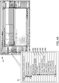
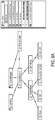
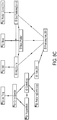
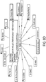
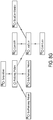
- FIGS. 5A, 5B , and 5C show the high-level control sequences (OB1, OB100, and OB35) are written in Ladder Logic, as it may be specified in some embodiments.
- FIG. 5A shows the ladder diagram for OB100 - complete restart program.
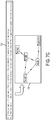
- FIG. 5B provides an illustration of the ladder diagram for OB1 - main program cycle.
- FIG. 5C is a ladder diagram for OB35 - a cyclic positioning program executed every 100 ms.
- the position control program block "Position_Control_Sim" receives input(s) from "Move” program block and sends output(s) to "Add” block.
- the position control is coded in SCL as shown in FIG. 6 below.
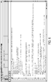
- FIG. 6 shows SCL Code for repositioning during oscillations, as it may be implemented in some embodiments.
- a "positioning" program coded in SCL similar to any other modern programming languages.
- conditions e.g., IF, ELSE, ELSEIF, THEN, END_IF
- loops e.g., IF, ELSE, ELSEIF, THEN, END_IF
- loops e.g., IF, ELSE, ELSEIF, THEN, END_IF
- comparisons e.g., assignment; and comments.
- the knowledge of a control program may include information regarding the structure and organization of the program blocks; the relationship between the program blocks (e.g. inputs/outputs, etc.); the control flow of the program blocks (e.g. timer-based cyclic execution); the parameters of the program blocks (e.g. temporary and global variables, etc.); the language constructs within a program block (e.g. loop, comments, etc.); and the dependencies between the variables within the entire control program.
- This knowledge holds important information of a control program. Such knowledge does not exist anywhere else and may be very hard to reconstruct outside the control program engineering environment.
- a temporary variable may indicate an abnormality of the control which could be the result of an erroneous sensor reading input.
- knowledge can be used in the later root-cause diagnostics. This knowledge is not preserved during compilation of the control program in a conventional engineering environment. The control code is compiled into the machine code and downloaded and executed on the controller device. The knowledge is lost. However, using the techniques described herein, such knowledge can be preserved in the engineering environment in the form of control models
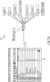
- FIGS. 7A - 7C show how control context models can be instantiated via the graphical development environment shown in FIGS. 4A - 4C by using the control variables of the control program.
- FIG. 7A a portion 700 of the graphical development environment (see e.g., FIG. 4B ) is shown on the left providing a set of control variables that are the basis for the control context ontology 705 on the right.
- the control program also contains control functions.
- the positioning control may consist of the following control functions: Startup [OB100], Reset_All [FC1], Doors_Generator [FC4], Position_Control_Sim [FC3], Main [OB1], etc.
- FIG. 7B a portion 710 of the graphical development environment (see e.g., FIG. 4A ) is shown on the left providing a set of control functions that are extracted to populate the control context ontology 715 on the right.
- FIG. 7C shows dependency graph representing relations between control variables 725 extracted from the implementation of control function Position_Control_Sim shown in the code snippet 720.
- the assignment command allows extracting a dependency relation between the control variables speed, acceleration and delatTime as well as between position, direction, speed and delatTime.
- the time causality is very simple since it is explicitly given by the sequence of logic control statements.
- a closed loop control e.g., PID
- the causal relationship is slightly more complicated because the value of a certain variable is not only dependent on the simultaneous values of other variables but also on the past values of itself and on other variables.
- the Control Model describes control variables that directly influence the performance of the control system and therefore also the control KPIs.
- the types of KPIs that are relevant for a certain application are defined by the type of control system and in many cases can be automatically derived from the context and added to the control context (e.g. in a state-discrete control system programmed with ladder logic, all timing information can be considered as an important KPI). Connecting such alarms (e.g., represented by an event context model) with control KPIs and additional control context information is extremely valuable for alarm management and diagnostics. By traversing the context graph, root causes for alarms can be discovered.
- FIGS. 8A - 8G provide additional examples of information which may be organized in the Control Model for the door assembly operation, according to some embodiments.
- FIG. 8A shows available types of Control Operators required for modeling a Positioning Control.
- the Control Program also Control Operators.
- the Positioning Control (subclass of ControlProgram) may comprise of the following classes/types of Positioning Control Operators: Move, Add, Position_Control_Sim and Main_OB1.
- a concrete Positioning Control is defined as a Control Program which consists of at least one instance of the Main_OB1 and the Position_Control_Sim operator. This formalization is shown in FIGS. 8B - 8G .
- FIG. 8B shows a formal definition of a Positioning Control program using existential quantification.
- FIG. 8C shows a Concrete instantiation of Main_OB1 for Positioning Control with Control Loop.
- the program code of the Position_Control_Sim Program Block can be further modeled as shown in FIG. 8D , which illustrates (Global) Control Variables are used by the Program Block.
- FIG. 8F provides the Control Variable LoopCount used as Control KPI.
- Certain Control Variables can be used to assess the quality of the control algorithm. These ControlVariables are referred to herein as ControlKPIs. They are particularly important for monitoring and optimization purposes and can be modeled as follows (using multiple inheritance).
- the control context model as shortly described above it tightly integrated with other context dimensions (e.g. asset, process and event context).
- FIG. 8G shows how a Control Variable can be linked to an event in the event model.
- control layer devices may include one or more central processing units (CPUs), graphical processing units (GPUs), or any other processor known in the art. More generally, a processor as used herein is a device for executing machine-readable instructions stored on a computer readable medium, for performing tasks and may comprise any one or combination of, hardware and firmware. A processor may also comprise memory storing machine-readable instructions executable for performing tasks. A processor acts upon information by manipulating, analyzing, modifying, converting or transmitting information for use by an executable procedure or an information device, and/or by routing the information to an output device.
- CPUs central processing units
- GPUs graphical processing units
- a processor may use or comprise the capabilities of a computer, controller or microprocessor, for example, and be conditioned using executable instructions to perform special purpose functions not performed by a general purpose computer.
- a processor may be coupled (electrically and/or as comprising executable components) with any other processor enabling interaction and/or communication there-between.
- a user interface processor or generator is a known element comprising electronic circuitry or software or a combination of both for generating display images or portions thereof.
- a user interface comprises one or more display images enabling user interaction with a processor or other device.
- Various devices described herein including, without limitation to the control layer devices and related computing infrastructure, may include at least one computer readable medium or memory for holding instructions programmed according to embodiments of the invention and for containing data structures, tables, records, or other data described herein.
- the term "computer readable medium” as used herein refers to any medium that participates in providing instructions to one or more processors for execution.
- a computer readable medium may take many forms including, but not limited to, non-transitory, non-volatile media, volatile media, and transmission media.
- Non-limiting examples of non-volatile media include optical disks, solid state drives, magnetic disks, and magneto-optical disks.
- Non-limiting examples of volatile media include dynamic memory.
- Non-limiting examples of transmission media include coaxial cables, copper wire, and fiber optics, including the wires that make up a system bus. Transmission media may also take the form of acoustic or light waves, such as those generated during radio wave and infrared data communications.
- An executable application comprises code or machine readable instructions for conditioning the processor to implement predetermined functions, such as those of an operating system, a context data acquisition system or other information processing system, for example, in response to user command or input.
- An executable procedure is a segment of code or machine readable instruction, sub-routine, or other distinct section of code or portion of an executable application for performing one or more particular processes. These processes may include receiving input data and/or parameters, performing operations on received input data and/or performing functions in response to received input parameters, and providing resulting output data and/or parameters.
- a graphical user interface comprises one or more display images, generated by a display processor and enabling user interaction with a processor or other device and associated data acquisition and processing functions.
- the GUI also includes an executable procedure or executable application.
- the executable procedure or executable application conditions the display processor to generate signals representing the GUI display images. These signals are supplied to a display device which displays the image for viewing by the user.
- the processor under control of an executable procedure or executable application, manipulates the GUI display images in response to signals received from the input devices. In this way, the user may interact with the display image using the input devices, enabling user interaction with the processor or other device.
- An activity performed automatically is performed in response to one or more executable instructions or device operation without user direct initiation of the activity.
Landscapes
- Physics & Mathematics (AREA)
- General Physics & Mathematics (AREA)
- Engineering & Computer Science (AREA)
- Automation & Control Theory (AREA)
- Programmable Controllers (AREA)
Claims (12)
- Verfahren zum Betreiben einer intelligenten programmierbaren Logiksteuereinheit (210), wobei das Verfahren Folgendes umfasst:Ausführen durch einen Prozessor, der in der intelligenten programmierbaren Logiksteuereinheit enthalten ist, eines Steuerprogramms zum Steuern eines Betriebs von Vorrichtungen in einem Automatisierungssystem;Extrahieren eines Steuermodells (225) aus dem Steuerprogramm anhand von kontextspezifischem Wissen (215) bezüglich des Steuerprogramms;Speichern durch ein nichtflüchtiges Speichermedium, das in der intelligenten programmierbaren Logiksteuereinheit enthalten ist, des Steuermodells;Verwenden durch eine Steuerüberwachungskomponente (245) des Steuermodells, um einen Überwachungsbetrieb bezüglich der Ausführung des Steuerprogramms auf der intelligenten programmierbaren Logiksteuereinheit (210) auszuführen; undErzeugen von Ereignissen durch die Steuerüberwachungskomponente (245) bezüglich des Betriebs der intelligenten programmierbaren Logiksteuereinheit als Reaktion auf den Überwachungsvorgang; undEinsetzen einer Überwachungsregel für eine Steuereinheitenvariable unter Verwendung eines Schlüsselleistungsindikators;wobei der Überwachungsvorgang umfasst, die Steuereinheitenvariable während der Ausführung des Steuerprogramms zu überwachen.
- Verfahren nach Anspruch 1, wobei der Überwachungsvorgang ferner Folgendes umfasst:
Überwachen mindestens einer Steuereinheitenfunktion während der Ausführung des Steuerprogramms. - Verfahren nach Anspruch 1, das ferner Folgendes umfasst:
Identifizieren eines oder mehrerer Fehler in dem Steuerprogramm unter Verwendung des Steuermodells. - Verfahren nach Anspruch 1, das ferner Folgendes umfasst:
Korrigieren des Steuerprogramms unter Verwendung des Steuermodells. - Verfahren nach Anspruch 1, das ferner Folgendes umfasst:
Anpassen mindestens eines Algorithmus, der in dem Steuerprogramm enthalten ist, anhand des Steuermodells. - Verfahren nach Anspruch 1, wobei das Steuermodell automatisch aus dem Programmcode in einer technischen Entwicklungsumgebung extrahiert wird.
- Verfahren nach Anspruch 1, wobei das Steuermodell Folgendes umfasst:erste Daten, die Strukturinformationen bezüglich Programmfunktionen, die durch das Steuerprogramm verwendet werden, umfassen; undzweite Daten, die Steuerflussinformationen bezüglich der Programmfunktionen umfassen.
- Verfahren nach Anspruch 1, wobei das Steuermodell Folgendes umfasst:
erste Daten, die Abhängigkeitsinformationen bezüglich Prozessvariablen und Variablen, die durch das Steuerprogramm verwendet werden, umfassen. - Verfahren nach Anspruch 8, wobei das Steuermodell ferner Folgendes umfasst:
zweite Daten, die Wissensleistungsindikatordefinitionen (KPI-Definitionen) bezüglich des Steuerprogramms umfassen. - Programmierbare Logiksteuereinheit (210), die Folgendes umfasst:
mindestens einen Prozessor, der konfiguriert ist zum:Ausführen eines Steuerprogramms gemäß einem Abtastzyklus zum Steuern eines Betriebs von Vorrichtungen in einem Automatisierungssystem;Extrahieren eines Steuermodells aus dem Steuerprogramm anhand von kontextspezifischem Wissen bezüglich des Steuerprogramms;Verwenden des Steuermodells, um einen Überwachungsvorgang bezüglich der Ausführung des Steuerprogramms auszuführen;Erzeugen von Ereignissen bezüglich des Betriebs der intelligenten programmierbaren Logiksteuereinheit als Reaktion auf den Überwachungsvorgang; undEinsetzen einer Überwachungsregel für eine Steuereinheitenvariable unter Verwendung eines Schlüsselleistungsindikators;wobei der Überwachungsvorgang umfasst, die Steuereinheitenvariable während der Ausführung des Steuerprogramms zu überwachen; undein nichtflüchtiges computerlesbares Speichermedium, das das Steuerprogramm und das Steuermodell speichert. - Programmierbare Logiksteuereinheit nach Anspruch 10, wobei der Überwachungsvorgang ferner Folgendes umfasst:
Überwachen mindestens einer Steuereinheitenfunktion während der Ausführung des Steuerprogramms. - Programmierbare Logiksteuereinheit nach Anspruch 10, wobei mindestens ein Prozessor ferner konfiguriert ist zum:
Anpassen mindestens eines Algorithmus, der in dem Steuerprogramm enthalten ist, anhand des Steuermodells.
Applications Claiming Priority (1)
| Application Number | Priority Date | Filing Date | Title |
|---|---|---|---|
| PCT/US2015/037373 WO2016209221A1 (en) | 2015-06-24 | 2015-06-24 | Control contextualization and reasoning about control |
Publications (2)
| Publication Number | Publication Date |
|---|---|
| EP3314340A1 EP3314340A1 (de) | 2018-05-02 |
| EP3314340B1 true EP3314340B1 (de) | 2021-11-17 |
Family
ID=53611001
Family Applications (1)
| Application Number | Title | Priority Date | Filing Date |
|---|---|---|---|
| EP15738532.9A Active EP3314340B1 (de) | 2015-06-24 | 2015-06-24 | Steuerungskontextualisierung und schlussfolgerung über die steuerung |
Country Status (4)
| Country | Link |
|---|---|
| US (1) | US10809692B2 (de) |
| EP (1) | EP3314340B1 (de) |
| CN (1) | CN107835964B (de) |
| WO (1) | WO2016209221A1 (de) |
Families Citing this family (19)
| Publication number | Priority date | Publication date | Assignee | Title |
|---|---|---|---|---|
| JP6532610B2 (ja) * | 2016-08-30 | 2019-06-19 | 三菱電機株式会社 | プログラム編集装置、プログラム編集方法及びプログラム編集プログラム |
| US10983511B2 (en) | 2017-02-14 | 2021-04-20 | Quest Automated Services, LLC | Automation control system |
| JP6930448B2 (ja) * | 2018-02-01 | 2021-09-01 | オムロン株式会社 | データサンプリング装置、及びデータサンプリング方法 |
| US10705511B2 (en) * | 2018-07-11 | 2020-07-07 | Siemens Aktiengesellschaft | Abstraction layers for automation applications |
| EP3671571A1 (de) | 2018-12-20 | 2020-06-24 | Siemens Aktiengesellschaft | Verfahren und system zur erzeugung eines modells für künstliche intelligenz |
| US11403541B2 (en) | 2019-02-14 | 2022-08-02 | Rockwell Automation Technologies, Inc. | AI extensions and intelligent model validation for an industrial digital twin |
| JP7183877B2 (ja) * | 2019-03-13 | 2022-12-06 | オムロン株式会社 | グラフ表示装置、グラフ表示方法、及びグラフ表示プログラム |
| JP7031627B2 (ja) * | 2019-03-13 | 2022-03-08 | オムロン株式会社 | 解析装置、解析方法、及び解析プログラム |
| JP7188198B2 (ja) * | 2019-03-13 | 2022-12-13 | オムロン株式会社 | グラフ表示装置、グラフ表示方法、及びグラフ表示プログラム |
| JP2020149300A (ja) * | 2019-03-13 | 2020-09-17 | オムロン株式会社 | グラフ表示装置、グラフ表示方法、及びグラフ表示プログラム |
| US11086298B2 (en) | 2019-04-15 | 2021-08-10 | Rockwell Automation Technologies, Inc. | Smart gateway platform for industrial internet of things |
| JP6664562B1 (ja) * | 2019-04-18 | 2020-03-13 | 三菱電機株式会社 | デバッグ支援装置、デバッグ支援方法、デバッグ支援プログラム |
| JP6692510B1 (ja) * | 2019-06-18 | 2020-05-13 | 三菱電機株式会社 | 解析装置、方法、及びプログラム |
| US11841699B2 (en) | 2019-09-30 | 2023-12-12 | Rockwell Automation Technologies, Inc. | Artificial intelligence channel for industrial automation |
| US11435726B2 (en) | 2019-09-30 | 2022-09-06 | Rockwell Automation Technologies, Inc. | Contextualization of industrial data at the device level |
| US11307554B2 (en) * | 2019-11-20 | 2022-04-19 | Younes Faraj | System and method for keyword-based PLC programming |
| US11249462B2 (en) | 2020-01-06 | 2022-02-15 | Rockwell Automation Technologies, Inc. | Industrial data services platform |
| US11726459B2 (en) | 2020-06-18 | 2023-08-15 | Rockwell Automation Technologies, Inc. | Industrial automation control program generation from computer-aided design |
| US20220043431A1 (en) * | 2020-08-05 | 2022-02-10 | Rockwell Automation Technologies, Inc. | Industrial automation control program utilization in analytics model engine |
Family Cites Families (10)
| Publication number | Priority date | Publication date | Assignee | Title |
|---|---|---|---|---|
| US20090204237A1 (en) * | 2001-08-10 | 2009-08-13 | Rockwell Automation Technologies, Inc. | System and method for dynamic multi-objective optimization of machine selection, integration and utilization |
| US9729639B2 (en) * | 2001-08-10 | 2017-08-08 | Rockwell Automation Technologies, Inc. | System and method for dynamic multi-objective optimization of machine selection, integration and utilization |
| JP4403794B2 (ja) | 2003-02-28 | 2010-01-27 | 株式会社デンソー | 制御プログラムの検査方法及び検査装置及び検査プログラム |
| US7451003B2 (en) * | 2004-03-04 | 2008-11-11 | Falconeer Technologies Llc | Method and system of monitoring, sensor validation and predictive fault analysis |
| CN102340270B (zh) | 2011-08-16 | 2013-12-25 | 沈阳工业大学 | 基于plc和变频器的双馈电动机节能控制方法 |
| US8762301B1 (en) * | 2011-10-12 | 2014-06-24 | Metso Automation Usa Inc. | Automated determination of root cause |
| KR101254598B1 (ko) * | 2012-08-23 | 2013-04-15 | 주식회사 유디엠텍 | Smⅴ를 이용한 plc 제어 프로그램의 인터록 기능 검증방법 |
| CN102981445B (zh) | 2012-12-03 | 2014-08-13 | 西安红宇矿用特种移动设备有限公司 | 一种基于plc的煤炭采制样机智能控制系统和方法 |
| US20150262095A1 (en) * | 2014-03-12 | 2015-09-17 | Bahwan CyberTek Private Limited | Intelligent Decision Synchronization in Real Time for both Discrete and Continuous Process Industries |
| AU2017200941B2 (en) * | 2016-02-10 | 2018-03-15 | Accenture Global Solutions Limited | Telemetry Analysis System for Physical Process Anomaly Detection |
-
2015
- 2015-06-24 US US15/738,143 patent/US10809692B2/en active Active
- 2015-06-24 EP EP15738532.9A patent/EP3314340B1/de active Active
- 2015-06-24 WO PCT/US2015/037373 patent/WO2016209221A1/en active Application Filing
- 2015-06-24 CN CN201580081213.4A patent/CN107835964B/zh active Active
Non-Patent Citations (1)
| Title |
|---|
| None * |
Also Published As
| Publication number | Publication date |
|---|---|
| CN107835964B (zh) | 2020-09-11 |
| US20180314225A1 (en) | 2018-11-01 |
| US10809692B2 (en) | 2020-10-20 |
| CN107835964A (zh) | 2018-03-23 |
| WO2016209221A1 (en) | 2016-12-29 |
| EP3314340A1 (de) | 2018-05-02 |
Similar Documents
| Publication | Publication Date | Title |
|---|---|---|
| EP3314340B1 (de) | Steuerungskontextualisierung und schlussfolgerung über die steuerung | |
| EP3335083B1 (de) | Reichhaltige kontextualisierung von automatisierungsdaten | |
| US10739746B2 (en) | Using soft-sensors in a programmable logic controller | |
| CN106354082B (zh) | 一种基于知识的可编程逻辑控制器 | |
| US12039292B2 (en) | Maintenance and commissioning | |
| US10018997B2 (en) | Non-intrusive data analytics in a process control system | |
| JP6551565B2 (ja) | 工程解析装置、工程解析方法、及び工程解析プログラム | |
| RU2683415C1 (ru) | Генерация событий с использованием контекстной информации на интеллектуальном программируемом логическом контроллере | |
| WO2021110388A1 (en) | System, device and method for model based analytics | |
| Xin et al. | Adaptive Model Verification for Modularized Industry 4.0 Applications | |
| Vogel-Heuser et al. | Integrated modeling of complex production automation systems to increase dependability | |
| Vasudevan et al. | Certifiability Analysis of Machine Learning Systems for Low-Risk Automotive Applications | |
| EP3063596B1 (de) | Regressionsverfahren zur änderungserkennung |
Legal Events
| Date | Code | Title | Description |
|---|---|---|---|
| STAA | Information on the status of an ep patent application or granted ep patent |
Free format text: STATUS: THE INTERNATIONAL PUBLICATION HAS BEEN MADE |
|
| PUAI | Public reference made under article 153(3) epc to a published international application that has entered the european phase |
Free format text: ORIGINAL CODE: 0009012 |
|
| STAA | Information on the status of an ep patent application or granted ep patent |
Free format text: STATUS: REQUEST FOR EXAMINATION WAS MADE |
|
| 17P | Request for examination filed |
Effective date: 20171220 |
|
| AK | Designated contracting states |
Kind code of ref document: A1 Designated state(s): AL AT BE BG CH CY CZ DE DK EE ES FI FR GB GR HR HU IE IS IT LI LT LU LV MC MK MT NL NO PL PT RO RS SE SI SK SM TR |
|
| AX | Request for extension of the european patent |
Extension state: BA ME |
|
| DAV | Request for validation of the european patent (deleted) | ||
| DAX | Request for extension of the european patent (deleted) | ||
| STAA | Information on the status of an ep patent application or granted ep patent |
Free format text: STATUS: EXAMINATION IS IN PROGRESS |
|
| STAA | Information on the status of an ep patent application or granted ep patent |
Free format text: STATUS: EXAMINATION IS IN PROGRESS |
|
| 17Q | First examination report despatched |
Effective date: 20201118 |
|
| GRAP | Despatch of communication of intention to grant a patent |
Free format text: ORIGINAL CODE: EPIDOSNIGR1 |
|
| STAA | Information on the status of an ep patent application or granted ep patent |
Free format text: STATUS: GRANT OF PATENT IS INTENDED |
|
| INTG | Intention to grant announced |
Effective date: 20210701 |
|
| GRAS | Grant fee paid |
Free format text: ORIGINAL CODE: EPIDOSNIGR3 |
|
| GRAA | (expected) grant |
Free format text: ORIGINAL CODE: 0009210 |
|
| STAA | Information on the status of an ep patent application or granted ep patent |
Free format text: STATUS: THE PATENT HAS BEEN GRANTED |
|
| AK | Designated contracting states |
Kind code of ref document: B1 Designated state(s): AL AT BE BG CH CY CZ DE DK EE ES FI FR GB GR HR HU IE IS IT LI LT LU LV MC MK MT NL NO PL PT RO RS SE SI SK SM TR |
|
| REG | Reference to a national code |
Ref country code: GB Ref legal event code: FG4D |
|
| REG | Reference to a national code |
Ref country code: DE Ref legal event code: R096 Ref document number: 602015075074 Country of ref document: DE |
|
| REG | Reference to a national code |
Ref country code: IE Ref legal event code: FG4D |
|
| REG | Reference to a national code |
Ref country code: AT Ref legal event code: REF Ref document number: 1448569 Country of ref document: AT Kind code of ref document: T Effective date: 20211215 |
|
| REG | Reference to a national code |
Ref country code: LT Ref legal event code: MG9D |
|
| REG | Reference to a national code |
Ref country code: NL Ref legal event code: MP Effective date: 20211117 |
|
| REG | Reference to a national code |
Ref country code: AT Ref legal event code: MK05 Ref document number: 1448569 Country of ref document: AT Kind code of ref document: T Effective date: 20211117 |
|
| PG25 | Lapsed in a contracting state [announced via postgrant information from national office to epo] |
Ref country code: RS Free format text: LAPSE BECAUSE OF FAILURE TO SUBMIT A TRANSLATION OF THE DESCRIPTION OR TO PAY THE FEE WITHIN THE PRESCRIBED TIME-LIMIT Effective date: 20211117 Ref country code: LT Free format text: LAPSE BECAUSE OF FAILURE TO SUBMIT A TRANSLATION OF THE DESCRIPTION OR TO PAY THE FEE WITHIN THE PRESCRIBED TIME-LIMIT Effective date: 20211117 Ref country code: FI Free format text: LAPSE BECAUSE OF FAILURE TO SUBMIT A TRANSLATION OF THE DESCRIPTION OR TO PAY THE FEE WITHIN THE PRESCRIBED TIME-LIMIT Effective date: 20211117 Ref country code: BG Free format text: LAPSE BECAUSE OF FAILURE TO SUBMIT A TRANSLATION OF THE DESCRIPTION OR TO PAY THE FEE WITHIN THE PRESCRIBED TIME-LIMIT Effective date: 20220217 Ref country code: AT Free format text: LAPSE BECAUSE OF FAILURE TO SUBMIT A TRANSLATION OF THE DESCRIPTION OR TO PAY THE FEE WITHIN THE PRESCRIBED TIME-LIMIT Effective date: 20211117 |
|
| PG25 | Lapsed in a contracting state [announced via postgrant information from national office to epo] |
Ref country code: IS Free format text: LAPSE BECAUSE OF FAILURE TO SUBMIT A TRANSLATION OF THE DESCRIPTION OR TO PAY THE FEE WITHIN THE PRESCRIBED TIME-LIMIT Effective date: 20220317 Ref country code: SE Free format text: LAPSE BECAUSE OF FAILURE TO SUBMIT A TRANSLATION OF THE DESCRIPTION OR TO PAY THE FEE WITHIN THE PRESCRIBED TIME-LIMIT Effective date: 20211117 Ref country code: PT Free format text: LAPSE BECAUSE OF FAILURE TO SUBMIT A TRANSLATION OF THE DESCRIPTION OR TO PAY THE FEE WITHIN THE PRESCRIBED TIME-LIMIT Effective date: 20220317 Ref country code: PL Free format text: LAPSE BECAUSE OF FAILURE TO SUBMIT A TRANSLATION OF THE DESCRIPTION OR TO PAY THE FEE WITHIN THE PRESCRIBED TIME-LIMIT Effective date: 20211117 Ref country code: NO Free format text: LAPSE BECAUSE OF FAILURE TO SUBMIT A TRANSLATION OF THE DESCRIPTION OR TO PAY THE FEE WITHIN THE PRESCRIBED TIME-LIMIT Effective date: 20220217 Ref country code: NL Free format text: LAPSE BECAUSE OF FAILURE TO SUBMIT A TRANSLATION OF THE DESCRIPTION OR TO PAY THE FEE WITHIN THE PRESCRIBED TIME-LIMIT Effective date: 20211117 Ref country code: LV Free format text: LAPSE BECAUSE OF FAILURE TO SUBMIT A TRANSLATION OF THE DESCRIPTION OR TO PAY THE FEE WITHIN THE PRESCRIBED TIME-LIMIT Effective date: 20211117 Ref country code: HR Free format text: LAPSE BECAUSE OF FAILURE TO SUBMIT A TRANSLATION OF THE DESCRIPTION OR TO PAY THE FEE WITHIN THE PRESCRIBED TIME-LIMIT Effective date: 20211117 Ref country code: GR Free format text: LAPSE BECAUSE OF FAILURE TO SUBMIT A TRANSLATION OF THE DESCRIPTION OR TO PAY THE FEE WITHIN THE PRESCRIBED TIME-LIMIT Effective date: 20220218 Ref country code: ES Free format text: LAPSE BECAUSE OF FAILURE TO SUBMIT A TRANSLATION OF THE DESCRIPTION OR TO PAY THE FEE WITHIN THE PRESCRIBED TIME-LIMIT Effective date: 20211117 |
|
| PG25 | Lapsed in a contracting state [announced via postgrant information from national office to epo] |
Ref country code: SM Free format text: LAPSE BECAUSE OF FAILURE TO SUBMIT A TRANSLATION OF THE DESCRIPTION OR TO PAY THE FEE WITHIN THE PRESCRIBED TIME-LIMIT Effective date: 20211117 Ref country code: SK Free format text: LAPSE BECAUSE OF FAILURE TO SUBMIT A TRANSLATION OF THE DESCRIPTION OR TO PAY THE FEE WITHIN THE PRESCRIBED TIME-LIMIT Effective date: 20211117 Ref country code: RO Free format text: LAPSE BECAUSE OF FAILURE TO SUBMIT A TRANSLATION OF THE DESCRIPTION OR TO PAY THE FEE WITHIN THE PRESCRIBED TIME-LIMIT Effective date: 20211117 Ref country code: EE Free format text: LAPSE BECAUSE OF FAILURE TO SUBMIT A TRANSLATION OF THE DESCRIPTION OR TO PAY THE FEE WITHIN THE PRESCRIBED TIME-LIMIT Effective date: 20211117 Ref country code: DK Free format text: LAPSE BECAUSE OF FAILURE TO SUBMIT A TRANSLATION OF THE DESCRIPTION OR TO PAY THE FEE WITHIN THE PRESCRIBED TIME-LIMIT Effective date: 20211117 Ref country code: CZ Free format text: LAPSE BECAUSE OF FAILURE TO SUBMIT A TRANSLATION OF THE DESCRIPTION OR TO PAY THE FEE WITHIN THE PRESCRIBED TIME-LIMIT Effective date: 20211117 |
|
| REG | Reference to a national code |
Ref country code: DE Ref legal event code: R097 Ref document number: 602015075074 Country of ref document: DE |
|
| PLBE | No opposition filed within time limit |
Free format text: ORIGINAL CODE: 0009261 |
|
| STAA | Information on the status of an ep patent application or granted ep patent |
Free format text: STATUS: NO OPPOSITION FILED WITHIN TIME LIMIT |
|
| 26N | No opposition filed |
Effective date: 20220818 |
|
| PG25 | Lapsed in a contracting state [announced via postgrant information from national office to epo] |
Ref country code: AL Free format text: LAPSE BECAUSE OF FAILURE TO SUBMIT A TRANSLATION OF THE DESCRIPTION OR TO PAY THE FEE WITHIN THE PRESCRIBED TIME-LIMIT Effective date: 20211117 |
|
| PG25 | Lapsed in a contracting state [announced via postgrant information from national office to epo] |
Ref country code: SI Free format text: LAPSE BECAUSE OF FAILURE TO SUBMIT A TRANSLATION OF THE DESCRIPTION OR TO PAY THE FEE WITHIN THE PRESCRIBED TIME-LIMIT Effective date: 20211117 |
|
| PG25 | Lapsed in a contracting state [announced via postgrant information from national office to epo] |
Ref country code: MC Free format text: LAPSE BECAUSE OF FAILURE TO SUBMIT A TRANSLATION OF THE DESCRIPTION OR TO PAY THE FEE WITHIN THE PRESCRIBED TIME-LIMIT Effective date: 20211117 |
|
| REG | Reference to a national code |
Ref country code: BE Ref legal event code: MM Effective date: 20220630 |
|
| PG25 | Lapsed in a contracting state [announced via postgrant information from national office to epo] |
Ref country code: LU Free format text: LAPSE BECAUSE OF NON-PAYMENT OF DUE FEES Effective date: 20220624 Ref country code: IE Free format text: LAPSE BECAUSE OF NON-PAYMENT OF DUE FEES Effective date: 20220624 |
|
| PG25 | Lapsed in a contracting state [announced via postgrant information from national office to epo] |
Ref country code: BE Free format text: LAPSE BECAUSE OF NON-PAYMENT OF DUE FEES Effective date: 20220630 |
|
| P01 | Opt-out of the competence of the unified patent court (upc) registered |
Effective date: 20230510 |
|
| PGFP | Annual fee paid to national office [announced via postgrant information from national office to epo] |
Ref country code: DE Payment date: 20220630 Year of fee payment: 9 |
|
| PGFP | Annual fee paid to national office [announced via postgrant information from national office to epo] |
Ref country code: IT Payment date: 20230627 Year of fee payment: 9 Ref country code: GB Payment date: 20230710 Year of fee payment: 9 Ref country code: CH Payment date: 20230907 Year of fee payment: 9 |
|
| PG25 | Lapsed in a contracting state [announced via postgrant information from national office to epo] |
Ref country code: HU Free format text: LAPSE BECAUSE OF FAILURE TO SUBMIT A TRANSLATION OF THE DESCRIPTION OR TO PAY THE FEE WITHIN THE PRESCRIBED TIME-LIMIT; INVALID AB INITIO Effective date: 20150624 |
|
| PG25 | Lapsed in a contracting state [announced via postgrant information from national office to epo] |
Ref country code: MK Free format text: LAPSE BECAUSE OF FAILURE TO SUBMIT A TRANSLATION OF THE DESCRIPTION OR TO PAY THE FEE WITHIN THE PRESCRIBED TIME-LIMIT Effective date: 20211117 Ref country code: CY Free format text: LAPSE BECAUSE OF FAILURE TO SUBMIT A TRANSLATION OF THE DESCRIPTION OR TO PAY THE FEE WITHIN THE PRESCRIBED TIME-LIMIT Effective date: 20211117 |
|
| PGFP | Annual fee paid to national office [announced via postgrant information from national office to epo] |
Ref country code: FR Payment date: 20240617 Year of fee payment: 10 |