EP3314253B1 - Récepteur optique accordable - Google Patents
Récepteur optique accordable Download PDFInfo
- Publication number
- EP3314253B1 EP3314253B1 EP16815454.0A EP16815454A EP3314253B1 EP 3314253 B1 EP3314253 B1 EP 3314253B1 EP 16815454 A EP16815454 A EP 16815454A EP 3314253 B1 EP3314253 B1 EP 3314253B1
- Authority
- EP
- European Patent Office
- Prior art keywords
- frequency
- light
- frequencies
- matching
- signals
- Prior art date
- Legal status (The legal status is an assumption and is not a legal conclusion. Google has not performed a legal analysis and makes no representation as to the accuracy of the status listed.)
- Active
Links
- 230000003287 optical effect Effects 0.000 title description 22
- 210000004369 blood Anatomy 0.000 claims description 73
- 239000008280 blood Substances 0.000 claims description 73
- 238000000034 method Methods 0.000 claims description 40
- 239000000470 constituent Substances 0.000 claims description 30
- 239000003990 capacitor Substances 0.000 claims description 21
- 238000000502 dialysis Methods 0.000 claims description 16
- 230000008859 change Effects 0.000 claims description 14
- 238000012544 monitoring process Methods 0.000 claims description 13
- 230000000903 blocking effect Effects 0.000 claims description 7
- 229910052757 nitrogen Inorganic materials 0.000 claims description 5
- 239000000203 mixture Substances 0.000 claims description 4
- 230000001052 transient effect Effects 0.000 claims description 2
- 238000005259 measurement Methods 0.000 description 23
- 238000001514 detection method Methods 0.000 description 19
- 230000001360 synchronised effect Effects 0.000 description 16
- QVGXLLKOCUKJST-UHFFFAOYSA-N atomic oxygen Chemical compound [O] QVGXLLKOCUKJST-UHFFFAOYSA-N 0.000 description 10
- 239000001301 oxygen Substances 0.000 description 10
- 229910052760 oxygen Inorganic materials 0.000 description 10
- 230000008569 process Effects 0.000 description 9
- 230000005540 biological transmission Effects 0.000 description 8
- 238000011282 treatment Methods 0.000 description 8
- 238000013459 approach Methods 0.000 description 7
- 238000001914 filtration Methods 0.000 description 7
- 238000010521 absorption reaction Methods 0.000 description 6
- 230000008901 benefit Effects 0.000 description 5
- 230000008878 coupling Effects 0.000 description 5
- 238000010168 coupling process Methods 0.000 description 5
- 238000005859 coupling reaction Methods 0.000 description 5
- 238000005516 engineering process Methods 0.000 description 5
- 239000000463 material Substances 0.000 description 5
- 238000001228 spectrum Methods 0.000 description 5
- 102000001554 Hemoglobins Human genes 0.000 description 4
- 108010054147 Hemoglobins Proteins 0.000 description 4
- 210000001367 artery Anatomy 0.000 description 4
- 210000001772 blood platelet Anatomy 0.000 description 4
- 238000004891 communication Methods 0.000 description 4
- 230000006870 function Effects 0.000 description 4
- 239000007924 injection Substances 0.000 description 4
- 238000002347 injection Methods 0.000 description 4
- 238000012545 processing Methods 0.000 description 4
- 239000002131 composite material Substances 0.000 description 3
- 238000013461 design Methods 0.000 description 3
- 230000002452 interceptive effect Effects 0.000 description 3
- 230000005855 radiation Effects 0.000 description 3
- 239000004065 semiconductor Substances 0.000 description 3
- IJGRMHOSHXDMSA-UHFFFAOYSA-N Atomic nitrogen Chemical compound N#N IJGRMHOSHXDMSA-UHFFFAOYSA-N 0.000 description 2
- 239000004215 Carbon black (E152) Substances 0.000 description 2
- DGAQECJNVWCQMB-PUAWFVPOSA-M Ilexoside XXIX Chemical compound C[C@@H]1CC[C@@]2(CC[C@@]3(C(=CC[C@H]4[C@]3(CC[C@@H]5[C@@]4(CC[C@@H](C5(C)C)OS(=O)(=O)[O-])C)C)[C@@H]2[C@]1(C)O)C)C(=O)O[C@H]6[C@@H]([C@H]([C@@H]([C@H](O6)CO)O)O)O.[Na+] DGAQECJNVWCQMB-PUAWFVPOSA-M 0.000 description 2
- 238000004458 analytical method Methods 0.000 description 2
- 230000017531 blood circulation Effects 0.000 description 2
- 238000002485 combustion reaction Methods 0.000 description 2
- 230000001419 dependent effect Effects 0.000 description 2
- 238000009826 distribution Methods 0.000 description 2
- 238000000605 extraction Methods 0.000 description 2
- 239000012530 fluid Substances 0.000 description 2
- 229930195733 hydrocarbon Natural products 0.000 description 2
- 150000002430 hydrocarbons Chemical class 0.000 description 2
- 230000010363 phase shift Effects 0.000 description 2
- 229910052708 sodium Inorganic materials 0.000 description 2
- 239000011734 sodium Substances 0.000 description 2
- 230000007480 spreading Effects 0.000 description 2
- 238000003892 spreading Methods 0.000 description 2
- 238000003325 tomography Methods 0.000 description 2
- XLYOFNOQVPJJNP-UHFFFAOYSA-N water Substances O XLYOFNOQVPJJNP-UHFFFAOYSA-N 0.000 description 2
- 230000018199 S phase Effects 0.000 description 1
- 230000009471 action Effects 0.000 description 1
- 239000000654 additive Substances 0.000 description 1
- 230000000996 additive effect Effects 0.000 description 1
- 230000003321 amplification Effects 0.000 description 1
- 230000003466 anti-cipated effect Effects 0.000 description 1
- 235000013405 beer Nutrition 0.000 description 1
- 230000007423 decrease Effects 0.000 description 1
- 238000010586 diagram Methods 0.000 description 1
- 239000000385 dialysis solution Substances 0.000 description 1
- 230000000694 effects Effects 0.000 description 1
- 238000005111 flow chemistry technique Methods 0.000 description 1
- 238000005534 hematocrit Methods 0.000 description 1
- 238000003384 imaging method Methods 0.000 description 1
- 230000006872 improvement Effects 0.000 description 1
- 238000004519 manufacturing process Methods 0.000 description 1
- 238000003199 nucleic acid amplification method Methods 0.000 description 1
- 230000000644 propagated effect Effects 0.000 description 1
- 238000009877 rendering Methods 0.000 description 1
- 230000004044 response Effects 0.000 description 1
- 238000005070 sampling Methods 0.000 description 1
- 230000035945 sensitivity Effects 0.000 description 1
- 229910052710 silicon Inorganic materials 0.000 description 1
- 239000010703 silicon Substances 0.000 description 1
- 230000003595 spectral effect Effects 0.000 description 1
- 238000004611 spectroscopical analysis Methods 0.000 description 1
- 238000003860 storage Methods 0.000 description 1
- 239000000126 substance Substances 0.000 description 1
- 238000012360 testing method Methods 0.000 description 1
- 239000002699 waste material Substances 0.000 description 1
Images


Classifications
-
- G—PHYSICS
- G01—MEASURING; TESTING
- G01N—INVESTIGATING OR ANALYSING MATERIALS BY DETERMINING THEIR CHEMICAL OR PHYSICAL PROPERTIES
- G01N33/00—Investigating or analysing materials by specific methods not covered by groups G01N1/00 - G01N31/00
- G01N33/48—Biological material, e.g. blood, urine; Haemocytometers
- G01N33/483—Physical analysis of biological material
- G01N33/487—Physical analysis of biological material of liquid biological material
- G01N33/49—Blood
-
- A—HUMAN NECESSITIES
- A61—MEDICAL OR VETERINARY SCIENCE; HYGIENE
- A61M—DEVICES FOR INTRODUCING MEDIA INTO, OR ONTO, THE BODY; DEVICES FOR TRANSDUCING BODY MEDIA OR FOR TAKING MEDIA FROM THE BODY; DEVICES FOR PRODUCING OR ENDING SLEEP OR STUPOR
- A61M1/00—Suction or pumping devices for medical purposes; Devices for carrying-off, for treatment of, or for carrying-over, body-liquids; Drainage systems
- A61M1/14—Dialysis systems; Artificial kidneys; Blood oxygenators ; Reciprocating systems for treatment of body fluids, e.g. single needle systems for hemofiltration or pheresis
-
- G—PHYSICS
- G01—MEASURING; TESTING
- G01J—MEASUREMENT OF INTENSITY, VELOCITY, SPECTRAL CONTENT, POLARISATION, PHASE OR PULSE CHARACTERISTICS OF INFRARED, VISIBLE OR ULTRAVIOLET LIGHT; COLORIMETRY; RADIATION PYROMETRY
- G01J1/00—Photometry, e.g. photographic exposure meter
- G01J1/42—Photometry, e.g. photographic exposure meter using electric radiation detectors
- G01J1/44—Electric circuits
- G01J1/46—Electric circuits using a capacitor
-
- G—PHYSICS
- G01—MEASURING; TESTING
- G01J—MEASUREMENT OF INTENSITY, VELOCITY, SPECTRAL CONTENT, POLARISATION, PHASE OR PULSE CHARACTERISTICS OF INFRARED, VISIBLE OR ULTRAVIOLET LIGHT; COLORIMETRY; RADIATION PYROMETRY
- G01J3/00—Spectrometry; Spectrophotometry; Monochromators; Measuring colours
- G01J3/02—Details
- G01J3/10—Arrangements of light sources specially adapted for spectrometry or colorimetry
- G01J3/108—Arrangements of light sources specially adapted for spectrometry or colorimetry for measurement in the infrared range
-
- G—PHYSICS
- G01—MEASURING; TESTING
- G01J—MEASUREMENT OF INTENSITY, VELOCITY, SPECTRAL CONTENT, POLARISATION, PHASE OR PULSE CHARACTERISTICS OF INFRARED, VISIBLE OR ULTRAVIOLET LIGHT; COLORIMETRY; RADIATION PYROMETRY
- G01J3/00—Spectrometry; Spectrophotometry; Monochromators; Measuring colours
- G01J3/28—Investigating the spectrum
- G01J3/42—Absorption spectrometry; Double beam spectrometry; Flicker spectrometry; Reflection spectrometry
- G01J3/433—Modulation spectrometry; Derivative spectrometry
- G01J3/4338—Frequency modulated spectrometry
-
- G—PHYSICS
- G01—MEASURING; TESTING
- G01N—INVESTIGATING OR ANALYSING MATERIALS BY DETERMINING THEIR CHEMICAL OR PHYSICAL PROPERTIES
- G01N21/00—Investigating or analysing materials by the use of optical means, i.e. using sub-millimetre waves, infrared, visible or ultraviolet light
- G01N21/17—Systems in which incident light is modified in accordance with the properties of the material investigated
- G01N21/25—Colour; Spectral properties, i.e. comparison of effect of material on the light at two or more different wavelengths or wavelength bands
- G01N21/31—Investigating relative effect of material at wavelengths characteristic of specific elements or molecules, e.g. atomic absorption spectrometry
-
- A—HUMAN NECESSITIES
- A61—MEDICAL OR VETERINARY SCIENCE; HYGIENE
- A61B—DIAGNOSIS; SURGERY; IDENTIFICATION
- A61B5/00—Measuring for diagnostic purposes; Identification of persons
- A61B5/0059—Measuring for diagnostic purposes; Identification of persons using light, e.g. diagnosis by transillumination, diascopy, fluorescence
- A61B5/0082—Measuring for diagnostic purposes; Identification of persons using light, e.g. diagnosis by transillumination, diascopy, fluorescence adapted for particular medical purposes
- A61B5/0084—Measuring for diagnostic purposes; Identification of persons using light, e.g. diagnosis by transillumination, diascopy, fluorescence adapted for particular medical purposes for introduction into the body, e.g. by catheters
-
- A—HUMAN NECESSITIES
- A61—MEDICAL OR VETERINARY SCIENCE; HYGIENE
- A61B—DIAGNOSIS; SURGERY; IDENTIFICATION
- A61B5/00—Measuring for diagnostic purposes; Identification of persons
- A61B5/02—Detecting, measuring or recording pulse, heart rate, blood pressure or blood flow; Combined pulse/heart-rate/blood pressure determination; Evaluating a cardiovascular condition not otherwise provided for, e.g. using combinations of techniques provided for in this group with electrocardiography or electroauscultation; Heart catheters for measuring blood pressure
- A61B5/026—Measuring blood flow
- A61B5/0261—Measuring blood flow using optical means, e.g. infrared light
-
- A—HUMAN NECESSITIES
- A61—MEDICAL OR VETERINARY SCIENCE; HYGIENE
- A61B—DIAGNOSIS; SURGERY; IDENTIFICATION
- A61B5/00—Measuring for diagnostic purposes; Identification of persons
- A61B5/145—Measuring characteristics of blood in vivo, e.g. gas concentration, pH value; Measuring characteristics of body fluids or tissues, e.g. interstitial fluid, cerebral tissue
- A61B5/14542—Measuring characteristics of blood in vivo, e.g. gas concentration, pH value; Measuring characteristics of body fluids or tissues, e.g. interstitial fluid, cerebral tissue for measuring blood gases
-
- A—HUMAN NECESSITIES
- A61—MEDICAL OR VETERINARY SCIENCE; HYGIENE
- A61B—DIAGNOSIS; SURGERY; IDENTIFICATION
- A61B5/00—Measuring for diagnostic purposes; Identification of persons
- A61B5/145—Measuring characteristics of blood in vivo, e.g. gas concentration, pH value; Measuring characteristics of body fluids or tissues, e.g. interstitial fluid, cerebral tissue
- A61B5/1455—Measuring characteristics of blood in vivo, e.g. gas concentration, pH value; Measuring characteristics of body fluids or tissues, e.g. interstitial fluid, cerebral tissue using optical sensors, e.g. spectral photometrical oximeters
- A61B5/14551—Measuring characteristics of blood in vivo, e.g. gas concentration, pH value; Measuring characteristics of body fluids or tissues, e.g. interstitial fluid, cerebral tissue using optical sensors, e.g. spectral photometrical oximeters for measuring blood gases
-
- A—HUMAN NECESSITIES
- A61—MEDICAL OR VETERINARY SCIENCE; HYGIENE
- A61M—DEVICES FOR INTRODUCING MEDIA INTO, OR ONTO, THE BODY; DEVICES FOR TRANSDUCING BODY MEDIA OR FOR TAKING MEDIA FROM THE BODY; DEVICES FOR PRODUCING OR ENDING SLEEP OR STUPOR
- A61M1/00—Suction or pumping devices for medical purposes; Devices for carrying-off, for treatment of, or for carrying-over, body-liquids; Drainage systems
- A61M1/36—Other treatment of blood in a by-pass of the natural circulatory system, e.g. temperature adaptation, irradiation ; Extra-corporeal blood circuits
- A61M1/3621—Extra-corporeal blood circuits
- A61M1/3627—Degassing devices; Buffer reservoirs; Drip chambers; Blood filters
-
- A—HUMAN NECESSITIES
- A61—MEDICAL OR VETERINARY SCIENCE; HYGIENE
- A61M—DEVICES FOR INTRODUCING MEDIA INTO, OR ONTO, THE BODY; DEVICES FOR TRANSDUCING BODY MEDIA OR FOR TAKING MEDIA FROM THE BODY; DEVICES FOR PRODUCING OR ENDING SLEEP OR STUPOR
- A61M2205/00—General characteristics of the apparatus
- A61M2205/33—Controlling, regulating or measuring
- A61M2205/3306—Optical measuring means
- A61M2205/3313—Optical measuring means used specific wavelengths
-
- A—HUMAN NECESSITIES
- A61—MEDICAL OR VETERINARY SCIENCE; HYGIENE
- A61M—DEVICES FOR INTRODUCING MEDIA INTO, OR ONTO, THE BODY; DEVICES FOR TRANSDUCING BODY MEDIA OR FOR TAKING MEDIA FROM THE BODY; DEVICES FOR PRODUCING OR ENDING SLEEP OR STUPOR
- A61M2230/00—Measuring parameters of the user
- A61M2230/20—Blood composition characteristics
- A61M2230/202—Blood composition characteristics partial carbon oxide pressure, e.g. partial dioxide pressure (P-CO2)
-
- A—HUMAN NECESSITIES
- A61—MEDICAL OR VETERINARY SCIENCE; HYGIENE
- A61M—DEVICES FOR INTRODUCING MEDIA INTO, OR ONTO, THE BODY; DEVICES FOR TRANSDUCING BODY MEDIA OR FOR TAKING MEDIA FROM THE BODY; DEVICES FOR PRODUCING OR ENDING SLEEP OR STUPOR
- A61M2230/00—Measuring parameters of the user
- A61M2230/20—Blood composition characteristics
- A61M2230/205—Blood composition characteristics partial oxygen pressure (P-O2)
-
- A—HUMAN NECESSITIES
- A61—MEDICAL OR VETERINARY SCIENCE; HYGIENE
- A61M—DEVICES FOR INTRODUCING MEDIA INTO, OR ONTO, THE BODY; DEVICES FOR TRANSDUCING BODY MEDIA OR FOR TAKING MEDIA FROM THE BODY; DEVICES FOR PRODUCING OR ENDING SLEEP OR STUPOR
- A61M2230/00—Measuring parameters of the user
- A61M2230/20—Blood composition characteristics
- A61M2230/207—Blood composition characteristics hematocrit
-
- G—PHYSICS
- G01—MEASURING; TESTING
- G01J—MEASUREMENT OF INTENSITY, VELOCITY, SPECTRAL CONTENT, POLARISATION, PHASE OR PULSE CHARACTERISTICS OF INFRARED, VISIBLE OR ULTRAVIOLET LIGHT; COLORIMETRY; RADIATION PYROMETRY
- G01J1/00—Photometry, e.g. photographic exposure meter
- G01J1/42—Photometry, e.g. photographic exposure meter using electric radiation detectors
- G01J1/44—Electric circuits
- G01J2001/4406—Plural ranges in circuit, e.g. switchable ranges; Adjusting sensitivity selecting gain values
-
- G—PHYSICS
- G01—MEASURING; TESTING
- G01J—MEASUREMENT OF INTENSITY, VELOCITY, SPECTRAL CONTENT, POLARISATION, PHASE OR PULSE CHARACTERISTICS OF INFRARED, VISIBLE OR ULTRAVIOLET LIGHT; COLORIMETRY; RADIATION PYROMETRY
- G01J3/00—Spectrometry; Spectrophotometry; Monochromators; Measuring colours
- G01J3/02—Details
- G01J3/10—Arrangements of light sources specially adapted for spectrometry or colorimetry
- G01J2003/102—Plural sources
- G01J2003/104—Monochromatic plural sources
-
- G—PHYSICS
- G01—MEASURING; TESTING
- G01J—MEASUREMENT OF INTENSITY, VELOCITY, SPECTRAL CONTENT, POLARISATION, PHASE OR PULSE CHARACTERISTICS OF INFRARED, VISIBLE OR ULTRAVIOLET LIGHT; COLORIMETRY; RADIATION PYROMETRY
- G01J3/00—Spectrometry; Spectrophotometry; Monochromators; Measuring colours
- G01J3/02—Details
- G01J3/10—Arrangements of light sources specially adapted for spectrometry or colorimetry
- G01J2003/102—Plural sources
- G01J2003/106—Plural sources the two sources being alternating or selectable, e.g. in two ranges or line:continuum
-
- G—PHYSICS
- G01—MEASURING; TESTING
- G01J—MEASUREMENT OF INTENSITY, VELOCITY, SPECTRAL CONTENT, POLARISATION, PHASE OR PULSE CHARACTERISTICS OF INFRARED, VISIBLE OR ULTRAVIOLET LIGHT; COLORIMETRY; RADIATION PYROMETRY
- G01J3/00—Spectrometry; Spectrophotometry; Monochromators; Measuring colours
- G01J3/28—Investigating the spectrum
- G01J3/42—Absorption spectrometry; Double beam spectrometry; Flicker spectrometry; Reflection spectrometry
- G01J3/433—Modulation spectrometry; Derivative spectrometry
- G01J2003/4334—Modulation spectrometry; Derivative spectrometry by modulation of source, e.g. current modulation
-
- G—PHYSICS
- G01—MEASURING; TESTING
- G01N—INVESTIGATING OR ANALYSING MATERIALS BY DETERMINING THEIR CHEMICAL OR PHYSICAL PROPERTIES
- G01N21/00—Investigating or analysing materials by the use of optical means, i.e. using sub-millimetre waves, infrared, visible or ultraviolet light
- G01N21/17—Systems in which incident light is modified in accordance with the properties of the material investigated
- G01N21/25—Colour; Spectral properties, i.e. comparison of effect of material on the light at two or more different wavelengths or wavelength bands
- G01N21/31—Investigating relative effect of material at wavelengths characteristic of specific elements or molecules, e.g. atomic absorption spectrometry
- G01N21/314—Investigating relative effect of material at wavelengths characteristic of specific elements or molecules, e.g. atomic absorption spectrometry with comparison of measurements at specific and non-specific wavelengths
- G01N2021/3181—Investigating relative effect of material at wavelengths characteristic of specific elements or molecules, e.g. atomic absorption spectrometry with comparison of measurements at specific and non-specific wavelengths using LEDs
-
- G—PHYSICS
- G01—MEASURING; TESTING
- G01N—INVESTIGATING OR ANALYSING MATERIALS BY DETERMINING THEIR CHEMICAL OR PHYSICAL PROPERTIES
- G01N2201/00—Features of devices classified in G01N21/00
- G01N2201/06—Illumination; Optics
- G01N2201/062—LED's
- G01N2201/0627—Use of several LED's for spectral resolution
-
- G—PHYSICS
- G01—MEASURING; TESTING
- G01N—INVESTIGATING OR ANALYSING MATERIALS BY DETERMINING THEIR CHEMICAL OR PHYSICAL PROPERTIES
- G01N2201/00—Features of devices classified in G01N21/00
- G01N2201/06—Illumination; Optics
- G01N2201/069—Supply of sources
- G01N2201/0691—Modulated (not pulsed supply)
-
- G—PHYSICS
- G01—MEASURING; TESTING
- G01N—INVESTIGATING OR ANALYSING MATERIALS BY DETERMINING THEIR CHEMICAL OR PHYSICAL PROPERTIES
- G01N2201/00—Features of devices classified in G01N21/00
- G01N2201/12—Circuits of general importance; Signal processing
Definitions
- Transmission of light through a medium consists of having a light emitter give off light, and the light then passes through the medium and is then incident on a photodetector.
- the emitter may be at least one light emitting diode (LEDs), laser, laser diode, or other device, and the photodetector could be a photodiode or other detection device.
- An array of LEDs may serve as emitters and a matching photodiode may be used for detection.
- the term matching means that the photodetector has electrical characteristics such that the discrete wavelengths emitted by the array of LEDs produce a current in the photodetector. The range of wavelengths over which the photodetector can produce a current is termed the photodetector bandwidth.
- the photodetector currents can be amplified and converted to voltages through the use of a gain stage termed a Trans-impedance Amplifier (Trans-Z Amplifier).
- US 2012/0154789 A1 discloses a system for determining information on the one or more constituents in the medium, wherein the medium is blood, namely an optical monitoring system.
- the known system comprises a containment vessel being a blood chamber wherein the blood is moving through the blood chamber, wherein the blood chamber is part of a device for monitoring the blood undergoing dialysis.
- the known system also comprises light emitters in the form of LED photo emitters which are configured to operate at different wavelengths.
- the known system comprises a photodetector on a side of the containment vessel opposite the light emitters.
- the known system comprises a multiplier for generating a mixed output signal.
- the known system also comprises a measuring circuit configured to provide information about the concentration of one or more constituents in the blood.
- US 4 800 885 A refers to a blood constituent monitoring apparatus and to methods with frequency division multiplexing.
- US 5 061 632 A refers to a capillary tube hemoglobinometer.
- US 2012/120384 A1 refers to a sensor clip assembly for an optical blood monitoring system.
- One aspect of the invention provides a system for determining information on one or more constituents in a medium, as defined with appended independent claim 1.
- the system includes, inter alia and as further defined with appended claim 1: (a) N light emitters L 1 ...L N , wherein each light emitter L x is configured to provide an amplitude modulated (AM) light at modulation frequency f x into a flow path of the medium from one side of a containment vessel for the medium, wherein each light emitter L x uses a different modulation frequency f x , and wherein N is an integer greater than 1, and x is an integer greater than or equal to 1 and less than or equal to N; (b) a photodetector, configured to receive the AM light from each light emitter after it passes through the flow path of the medium, and convert the AM light to an electrical signal characterized by a summation of frequency components from each modulation frequency f x ; and (c) one or more measuring circuits, configured to provide information about a concentration of
- the medium is blood moving through a blood chamber.
- the blood chamber is part of a device for monitoring blood undergoing dialysis.
- the system further includes: a blocking capacitor configured to remove an offset from the electrical signal; a multiplier, configured to generate two mixed output signals by multiplying the electrical signal without DC offset and two matching signals, as defined in appended independent claim 1.
- the measuring circuit is further configured to provide a phase difference between a phase of an f x frequency component of the electrical signal and a phase of a current driving the L x emitter.
- the measuring circuit is further configured to determine a change in the phase difference, wherein the change in the phase difference provides information about a change in the composition of the medium.
- Another aspect of the invention provides a method for determining information on one or more constituents in a medium, according to appended independent claim 5: the method includes, inter alia and as further defined with claim 5: (a) varying, by a driving circuit, current provided to N light emitters L I ...L N in a sinusoidal manner so that each light emitter L x provides an amplitude modulated (AM) light at modulation frequency f x into a flow path of the medium from one side of a containment vessel for the medium, wherein each light emitter L x uses a different modulation frequency f x , and wherein N is an integer greater than 1, and x is an integer greater than or equal to 1 and less than or equal to N ; (b) receiving, by a photodetector, the AM light from each light emitter after it passes through the flow path of the medium and converting the AM light to an electrical signal characterized by a summation of frequency components from each modulation frequency f x ; (c) extracting, by a measuring
- the medium is blood moving through a blood chamber.
- the blood chamber is part of a device for monitoring blood undergoing dialysis.
- the method further includes: (a) removing a DC offset from the electrical signal; (b) generating, by a multiplier, two mixed output signals by multiplying the electrical signal without DC offset and two matching signals, wherein the two matching signals have frequencies f y and f z , and (c) extracting, by a bandpass filter, two corresponding filtered signals from the two mixed output signals, in one embodiment the two filtered signals having frequencies equal to 2 ⁇ f y and 2 ⁇ f z , and (d) determining, by the measuring circuit, values V y from the filtered signal when the matching frequency is f y and V z from the filtered signal when the matching frequency is f z , and V y and V z are related to the amplitudes of the f y and f z frequency components in the electrical signal, where the log ratios of V y and V z includes the information about the concentration of the constituents.
- the method further includes: (a) removing a DC offset from the electrical signal; (b) generating, by a multiplier, two mixed output signals by multiplying the electrical signal without DC offset and two matching signals, wherein in one embodiment the two matching signals have frequencies f y plus an offset frequency and f z plus the offset frequency, and (c) extracting, by a bandpass filter, two corresponding filtered signals from the two mixed output signals, the two filtered signals having frequencies equal to the offset frequency, and (d) determining, by the measuring circuit, values V y from the filtered signal when the matching frequency is f y plus the offset frequency and V z from the filtered signal when the matching frequency is f z plus the offset frequency, and V y and V z are related to the amplitudes of the f y and f z frequency components in the electrical signal, where the log ratios of V y and V z includes the information about the concentration of the constituents.
- the method further includes determining, by the measuring circuit, a phase difference between a phase of an f x frequency component of the electrical signal and a phase of a current driving the L x emitter.
- the method further includes determining, by the measuring circuit, a change in the phase difference, wherein the change in the phase difference provides information about a change in the composition of the medium.
- Yet another aspect of the disclosure provides a non-transient computer readable medium containing program instructions to cause the system of claim 1 to execute the steps of the method of claim 5.
- the emitter-photodiode system described in the Background section has some inherent drawbacks, mostly linked to the limitations of photodiodes in the real world. For example, photodiode bandwidth may reduce overall response of the system rendering some emitter-photodiode systems useless.
- embodiments of the disclosure treat the emitter-photodiode system in a similar manner as a communications technology system.
- Communications technology uses various techniques, in particular, the concepts applicable to different methods of amplitude modulation (AM) and demodulation. These concepts are applied in various instances, for example, AM radio and AM broadcasting. There is an inherent improvement in the use of synchronous detection compared to the use of modulation envelope detection. Utilizing techniques in communications technology, the emitter-photodiode system may be improved upon.
- AM amplitude modulation
- demodulation demodulation
- FIG. 1 A model of a commonly realizable photodetector 106 is shown in FIG. 1 . As provided, only the output terminals of the model can be accessed in the real world as shown in this "black box" model.
- FIG. 1 also provides the dynamics of the photodiode photodetector 106. Diodes are made by fusing dissimilar semi-conductor materials (such as Silicon) which are "doped" with chemicals to create the sensitivity to a bandwidth of light wavelengths. In a diode, electrical current only flows in one direction on each cycle of the frequency of the impressed light. Internal to the black box is a theoretical or ideal photodiode 108 which has no limitations to current production or speed within its bandwidth.
- any wavelength in its bandwidth will generate a half wave rectified current when the diode is forward biased by the impressed light signal from a light emitter.
- the frequency of the current matches that of the light.
- Frequency is determined in this case by dividing the speed of light (approximately 3 ⁇ 10 8 meters/second) by the wavelength in meters. The resulting frequencies in the near infrared and visible light spectrum measure in the terahertz range.
- the photodiode photodetector 106 receives various light input from ambient sources identified as ambient light 102 and a desired light signal 104 from a light emitter.
- the light signal is impressed on the junction of the photodiode and the internal junction capacitance along with leakage of the semi-conductor material result in a lowpass filter.
- the light signal is alternating current in the terahertz frequency range (with cycles so close together in time that the light signal is shown as a continuous block).
- the equivalent circuit is unable to respond to the terahertz frequency thus resulting in the output of the photodiode photodetector 106 being a rectified and filtered Direct Current (DC) signal with amplitude proportional to the amplitude of the impressed light signal (i.e., the combination of the ambient light 102 and the desired light signal 104).
- DC Direct Current
- the "ideal" characteristics are spoiled by the capacitance of the internal junction "space charge layer” and small leakage currents in the semiconductor material.
- these are represented by a discrete capacitor 110 (collective of all internal capacitances) and a discrete resistor 112 (collective of all leakages), respectively.
- This resistor-capacitor (RC) network forms a "lowpass filter” which filters the extremely high frequency components of the light impressed and detected by the ideal diode 108. Due to this lowpass filtering of the detected current, rather than a half wave rectified representation of the light waveform appearing at the black box terminals, a current proportional to the intensity of the impressed light without frequency appears - in other words a DC current.
- Alternating Current (AC) frequency component of the impressed light could be preserved in the photodiode photodetector and components capable of operating at these frequencies were available, then there would be a way to distinguish the wavelength of the received light illuminating the photodetector. But with only DC current being produced for all light impressed on the photodetector within its bandwidth, there is no ability to distinguish what individual wavelengths are being received. The photodetector simply integrates all of the light energy received in its bandwidth and produces a composite DC current as a result. This would not be a problem if ambient light sources could be eliminated in all situations.
- AC Alternating Current
- the desired wavelength of light being detected from interfering ambient light In attempts to distinguish the desired wavelength of light being detected from interfering ambient light, a common method used and commercialized are so called “Lock-in" amplifiers. In such systems the desired light beam is either physically chopped by a rotating disk with holes in it or by electronic means which, in effect, keys the light on and off at a specified rate.
- the photodetector amplification circuitry is synchronized to the light chopping so it only processes signals when the desired light is known to be emitting. During the period of no light emission, the background level of ambient light is measured and subtracted from the time when active light is known to be emitting. This difference is considered to be the desired signal amplitude.
- a more effective method is the application of communications amplitude modulation techniques.
- This approach is based on the realization that while the lowpass filter characteristic of the photodetector will not preserve the frequency of the light, the light can be AM modulated with a frequency that is low enough that the photodetector acts as a conventional envelope detector as found in traditional AM receivers.
- the carrier instead of the carrier being in the radio frequency (RF) spectral region, the carrier is the light determined by the emitter's wavelength.
- RF radio frequency
- the tone modulation amplitude at a fixed modulation index is proportional to the strength of the carrier - therefore, the strength of the light signal. Therefore, processing the modulation sideband allows for distinguishing the wavelength of interest over ambient interference.
- the concept of the system described herein is to view the bandwidth of the photodetector as a segment of RF spectrum. This is possible because it is generally agreed that light is an electro-magnetic energy which behaves very much like RF.
- an AM receiver is built to tune any of the frequencies (or wavelengths where wavelength is the speed of light - 3 ⁇ 10 8 meters/second - divided by the frequency).
- the conventional diode detector in an AM receiver generates asynchronous envelope detection - the same as the previously described light photodetector - but in the envisioned system the frequency of the RF carrier is low enough that circuit provisions are made to add a physical lowpass filter.
- the lowpass filter is made up of an appropriate capacitor and resistor that are tuned to eliminate all frequencies above the music audio frequency range.
- the antenna receives all transmitted frequencies, the tunable filter selects a frequency of interest, and in this case, Station D, and the AM diode detector functions as an envelope detector and a lowpass filter based on the appropriate capacitor and resistor combination.
- the signal from the AM diode detector is provided in an Amplifier which then goes to the speaker for audio out.
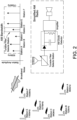
- each receiver contains a set of selective tuning circuits, between the antenna and the AM diode detector as provided in FIG. 2 , used to "pre-select" the signal to be received.
- the bandwidth of the tuning circuits is narrow enough (sufficiently high enough Quality factor - or "Q") to eliminate all but the specific radio station one desires to listen to.
- FIG. 2 illustrates the AM radio concept and spectrum.
- a tunable optical receiver in connection with a light measurement system that enables control over the transmission systems of the light signals.
- the described system enables selection of wavelengths in the photodetector bandwidth that are conveniently absorbed and scattered by specific constituents in the medium being measured.
- Unique modulation frequencies are assigned to each of the transmitted wavelengths.
- Each of the modulation frequencies and its corresponding transmitted wavelengths are selected to be non-harmonically related, and thus will act as "tags" for the respective light signals.
- the tunable optical receiver may be configured to use asynchronous and/or synchronous detection of the modulation tags.
- the application of this tunable technology can form the basis of a bedside diagnostic suite for future clinical treatments. Two example embodiments will be provided herein to describe a system and method of dealing with ambient light. One embodiment applies to an asynchronous receiver and the second embodiment to a synchronous receiver.
- the approach is similar to AM transmission principles discussed but with modified electronic signal processing techniques. Unlike in the case of the AM receiver, there are no currently available components that will function in visible light frequency range to "pre-select" a particular light signal to receive and measure. Therefore, the electronic components to build a tunable filter with a high Q in the optical frequency range are unavailable. As such, in the circuit architecture of the AM receiver of FIG. 2 when applied to optical frequencies, the photodetector will receive all generated and ambient light simultaneously and demodulate them. Thus, the output electrical form is the sum of all signal contributions including any undesired light signals.
- the light is either continuous wave (on all the time - CW) or keyed on and off (On-Off Keying - OOK) as in the Lock-in Amplifier schemes.
- the absorption and scattering of the light through the medium to be measured reduces the signal where the photodetector quantifies it for processing using Beer's Law.
- AM radio analogy this is like a radio station either turning on the transmitter in CW mode or toggling the transmitter on and off in OOK mode, but never playing any programming material (music, talk, etc.) - what is termed in the broadcast industry as "dead air.”
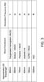
- FIG. 3 suggests some possible wavelengths for those parameters. The designer then selects frequencies of M(t) to "tag" each wavelength strategically for independent detection in the receiver. In FIG. 3 , wavelengths can be "tagged” with a modulation frequency M(t) to distinguish light intensities affected by different blood constituents. This approach removes ambient light interference, quantifies, and offers significant signal to noise margins for otherwise difficult to measure components of Human blood. This approach can be used equally well in other applications outside of blood such as monitoring purity of hydraulic fluid in aircraft.
- each wavelength of light is individually chosen to measure Oxygenated Hemoglobin ( ⁇ 660nm), Sodium ( ⁇ 590nm), Platelets ( ⁇ 750nm), Isosbestic Hemoglobin ( ⁇ 800nm), Carboxi-Hemoglobin ( ⁇ 790nm) and Water ( ⁇ 1300nm).
- the AM modulation "frequency tags" are shown as well in FIG. 3 (f1 to f6, which are not harmonically related and separated sufficiently to be individually filtered by conventional filtering techniques (analog, active filter, digital, etc.)).
- a current source may be used to drive the LED.
- the photon yield is directly proportional to the current flowing through the device.
- Photon yield is directly related to the light intensity. Given an LED that emits light at a specific wavelength (for example, one of the wavelengths provided in FIG. 3 ) the higher the photon yield, the higher the light intensity.
- the current source driving the LED may be programmed to change current delivered to the LED in a specified fashion, for example, in a sinusoidal fashion with a frequency matching one of the modulation frequencies M(t) provided in FIG. 3 .
- the LED's light intensity (photon yield) will vary to a maximum with current in the positive cycle and then to nearly zero (or zero) in the negative cycle.
- a "tagged" light is realized thus the light emitted by the LED is AM modulated with modulation frequency M(t).
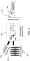
- An example waveform showing a desired "tagged” light 404 is provided in FIG. 4 .
- M(t) is preferred to be sinusoidal.
- M(t) may be a frequency in the range of 100 Hz to 500 kHz.
- the 100 Hz lower end is limited by the size of coupling capacitors, since the size of coupling capacitors increases as frequency decreases.
- Common optical systems are based on DC and need to be compensated for temperature drifts, input biases to amplifiers, and DC offsets, etc. By operating an AC system, some of the problems with a DC system are alleviated. By choosing an acceptable 100 Hz frequency in the AC system, acceptable sizes of a coupling capacitors may be realized.
- the 500 kHz upper end on M(t) is limited by electromagnetic (EM) radiation. At RF frequencies or frequencies above 500 kHz, EM radiation should be taken into account. Some jurisdictions have radiation emission standards to limit RF emissions in medical devices, for example, the International Electrotechnical Commission IEC 60601 standard.
- the photodetector 406 output current sums the DC levels from the received signals with any and all ambient interference - plus the modulation tones.
- Ambient light 402 and desired light 404 produce a sinusoidal signal 414. Because ambient light 402 is not modulated, it shows up as a DC component and adds with the DC component of signal 404 at item 414 with M(t) of the desired light offset by the total DC signal at 414. All are then amplified and converted to voltages through a Trans-Z amplifier.
- the DC component is removed (including all interfering and ambient light) leaving only the modulation frequencies of the individual "tagged" signals of interest. This is key to the removal of all interfering ambient light signals in the environment the measurements are made in.
- each frequency can be independently filtered and asynchronously envelope-detected with an additional detector for each tag frequency.
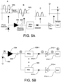
- FIG. 5A-B shows this type of arrangement of the receiver where individual filters 508-1 through 508-n may be bandpass filters that select the lower modulation frequency of the different desired signals. In some cases if only one modulation frequency is used, then only one path exists as in FIG. 5A .
- the 510-1 through 510- n diodes are detectors that rectify the signal from the 508-1 through 508- n filters. Using lowpass RC filters 512-1 through 512- n , the rectified signals are smoothed out. This smoothed DC level is proportional to the light amplitude at the respective tagged wavelength.
- sample and hold circuits 514-1 through 514- n are provided to select a single sampled voltage value on the smoothed signals for interface to digital processing systems.
- FIG. 5A shows a simple case when only one tagged signal is detected.
- the different graphs are shown as example representations of what the signal may look like in time as it propagates through the stages of the receiver.
- a preferred sinusoidal signal M(t) with a DC offset is received (as in FIG. 4 ).
- the DC signal is removed thereby giving the graph depicted at point B.
- the DC signal removal signifies removal of the ambient signal.
- the rectified signal is provided at point C.
- the detector in this case operates as a half-wave rectifier, but it is understood that a diode bridge circuit or other circuit may be used to full-wave rectify the signal from point B.
- FIG. 5B shows that the photodetector 502 may receive multiple tagged light with undesired light signals and the intensity of each of the desired signals may be quantified as a voltage in parallel using a similar process shown in FIG. 5A .
- FIG. 5B multiple outputs would be read in parallel from each of the sample and hold circuits 514-1 through 514- n .
- every component coming after blocking capacitor 506 may be generally referred to as being part of a measuring circuit since the collective effort is to measure the amplitude of the signal at point B.
- E A ( 1 + B M t Cos ⁇ L t
- E the overall wave amplitude at any given time
- A the maximum voltage of the AM waveform
- B the modulation index (a value from 0 - 1).
- B is always 1.
- M ( t ) is the modulation frequency function which may be defined as Cos ⁇ M t, with ⁇ M being the frequency of modulation measured in radians/second.
- ⁇ L is the frequency of the light signal measured in radians/second
- t is the time the snapshot of that this waveform is taken for analysis.
- the DC offset is the first A term.
- the second term is simply the modulation term of frequency ⁇ M .
- the negative of the modulation frequency per equation 2 is not realizable due to physical constraints of the real world.
- an asynchronous detector will require a separate bandpass filter to select the M(t) from the composite detected modulation at the output of the Trans-Z amplifier 504 and series capacitor 506.
- the selection of M(t) frequencies must be such that there is no harmonic relationships that will excite the incorrect filter, and that the M(t) frequencies are separated enough in frequency that the Q of the bandpass filters are reasonable and realizable. This is the complexity and design constraints on the realization of this embodiment of the tunable optical receiver.
- another method to receive the light signals is to synchronously detect using the original modulation frequency from the transmitter side as the base injection frequency.
- the synchronous detection is advantageous compared to the asynchronous due to lower component count and less rigor in design of selective filters 508 of FIG. 5B .
- synchronous detection also provides for potential differential phase measurement of the received modulation phase compared to that transmitted through the medium under test.
- phase differences may be important information included in these phase differences, for example, the ability to use the same signal to sense two components or properties - one component sensed through the signal's amplitude and the other component through the signal's phase.
- Phase differences between an input light signal and an output light signal occur when the wave velocity slows down as the wave travels from one medium to another.
- the phase of the initial signal is known, and the phase of the received signal can be measured. The difference in phase between the two signals may be calculated.
- the difference in phase between the input signal and the obtained signal may average about ⁇ 1 degrees.
- a microclot (much denser than blood) moves through the artery, this may affect the light velocity propagated through the artery. This may show up as a ⁇ degree change in phase to detect the microclot as it passes.
- the phase shift from ⁇ 1 degrees to ⁇ 1 + ⁇ degrees can be seen and the signal may be used to identify that a microclot just passed through the artery.
- Different bodies may produce different phase shifts, therefore, phase of a signal provides an additional dimension to recognize bodies in a medium while sensing for a constituent of the medium with the amplitude of the signal.
- FIG. 6 illustrates one embodiment of the tunable optical receiver which uses synchronous detection of the modulation tags.
- This system represents an example where a number of measurements through a blood chamber filled with human blood are made. Based on the governing mathematics below, it can be shown that as the processor tuning frequency is changed in each receiver element to correspond to a "tag" frequency, an independent measurement of the medium can be made.
- Equation 6 For example, suppose A M3 is of interest for a given interval of time. To receive this signal specifically, the processor tuning line to the four quadrant multiplier is set by the processor to ⁇ M3 .
- D signifies the detected signals
- a M is the amplitude of each of the individual light signals
- C is the amplitude of the processor injection signal (a constant)
- cos ⁇ Mn t is the light wave tags detected out of the Trans-Z Amplifier
- ⁇ Mn is the radian frequency of the modulation tags measured in radians/second
- t is the time the snapshot of this waveform is taken for analysis.
- the third term in equation 7 there are two ways to filter the ⁇ M3 component.
- the first is to follow the four quadrant multiplier with a bandpass filter tuned to 2 ⁇ M3 , as provided in FIG. 7B , followed by a root mean square (RMS) voltmeter, a diode/RC filter circuit with a sample and hold, as in FIG. 5 , or other measurement circuit.
- the bandpass filter will reject all the rest of the frequency terms from the four quadrant multiplier.
- the second way is use a lowpass filter to measure the DC offset of the output of the four quadrant multiplier - which is the amplitude of ( ⁇ M3 - ⁇ M3 ). All of the rest of the frequency terms from the Four Quadrant Multiplier are rejected by the lowpass filter. Since the second way is measuring a DC signal, it is important that a blocking capacitor is used after the Trans-Z Amplifier as in FIGS. 7A and 7B to eliminate any possible DC feedthrough from the Trans-Z Amplifier circuit.
- another option in detection is to shift the processor tuning frequency by a fixed offset - such as 200Hz - from the desired tag frequency ⁇ M3 .
- a lowpass filter will yield a 200Hz signal proportional to the amplitude of the light signal. In some instances, this signal may be easier to measure than a DC signal.
- the amplitude of the signal provided by the processor tuning frequency, C applies a gain factor to the overall detection process.
- FIG. 6 shows a system, based on some embodiments of the disclosure, using synchronous detection where the receiver element(s) are under processor tuning control.
- the figure uses the option of filtering twice the tag frequency, taking advantage of the spectrum spreading as a result - thus simplifying the filter designs.
- this system is advantageous in situations that exhibit steady state transmission of the light sources simultaneously (not pulsed).
- FIGS. 7A and 7B illustrate some embodiments of the synchronous receiver architecture.
- item 610 may be a lowpass filter or a bandpass filter for some offset frequency.
- This architecture may be used when sensing a DC offset as the amplitude corresponding to the selected frequency component.
- This architecture may also be used when sensing a low frequency signal at some offset frequency, for example, 200 Hz.
- the amplitude of the offset frequency signal in this case, corresponds to the output of the selected frequency component.
- FIG. 7B is provided separately to show the architecture where a bandpass filter may be used to select a signal that has a frequency twice the selected component's frequency. This approach takes advantage of frequency spreading, so the amplitude of the signal with frequency twice the selected component's frequency corresponds to the selected frequency component.
- a pulsed system (time domain multiplexed) system with tuning agility by processor control is possible.
- the filters should be designed and the measurements timed such that appropriate settling times are taken into account. There is a trade-off between filter Q and settling time - they are inversely related. The application of this tunable technology can form the basis of a bedside diagnostic suite for future clinical treatments.
- FIG. 8 illustrates a system that may take advantage of a synchronous optical receiver according to some embodiments of the disclosure.
- the system in FIG. 8 is used to measure blood constituents utilizing some embodiments of the disclosure.
- An LED current driver 802 produces multiple currents to drive an LED array 804.
- the LED array 804 contains LED1 to LEDN.
- Each LED in the LED array 804 operates at a different wavelength, and the LED current driver 802 is configured to modulate the current provided to each LED.
- Each modulated current behaves in a sinusoidal manner, with frequency much lower than the frequencies of the LEDs in the LED array 802.
- the modulated currents all have different frequencies from one another and do not exhibit a harmonic relationship with each other.
- FIG. 8 shows that processor 824 controls the LED current driver 802, so in some embodiments, the processor 824 may determine which modulation frequencies the LED current driver 802 should provide to each LED in the LED array 804.
- Light from the LED array 804 is incident on a blood chamber 808 and then through a blood flow path 806 and then to a photodetector or photosensor 810 which may be a photodiode.
- the photosensor 810 collects and integrates all light input (including ambient light) and generates a current.
- the current is then amplified and converted to a voltage signal by Trans-Z amplifier 812.
- a DC blocking capacitor is used to filter out the ambient light and introduce the amplified signal to the multiplier 814.
- the composite signal received at the multiplier 814 contains M(t) frequency components from the multiple LEDs in the LED array 804.
- the processor 824 provides to the multiplier 814, a frequency that is equal to the M(t) modulating frequency of LED2.
- the multiplier 814 then generates new frequency components including a frequency component that is two times the M(t) modulating frequency of LED2.
- Bandpass filter 816 is designed with a center frequency at two times the modulating frequency of LED2, so the bandpass filter 816 selects this frequency and attenuates all other frequencies of the LEDs.
- the detector 818, RC filter 820, and S/H 822 all operate as in FIG. 5 to extract a value corresponding to the amplitude of the signal with twice the modulating frequency of LED2. This value is provided to processor 824, and processor 824 may communicate this value to other systems and/or interpret the concentration of the constituent sensed by LED2 by using the amplitude of the signal driving LED2 and the value received by the S/H 822.
- LED2 was used as an example, but any of the modulation frequencies M(t) of the LEDs in the LED array 804 may have been tuned to.
- using the bandpass filter 816 to select twice the modulating frequency is also used as an example.
- the processor 824 may provide a frequency different from one of the modulating frequencies of an LED in the LED array 804, and bandpass filter 816 may be substituted for a lowpass filter depending on the method of sensing.
- the dashed line linking the bandpass filter 816 and the processor 824 is an optional path to determine the phase difference between the signal from the bandpass filter 816 and one of the M(t) modulation frequency current signals provided to the LED array 804 by LED current driver 802.
- the dotted line signal may drive a phase locked loop or algorithm or system included in the processor 824 or an external equivalent device inserted in the dotted line.
- a frequency divider is included in the processor 824 to correct for the frequency adjustments of the multiplier. For example, if the signal from the bandpass filter 816 has a frequency that is twice that of the modulated frequency current signal, then the processor 824 divides this frequency by 2 for the phase comparison.
- example frequency tags were provided to measure the concentration of different blood constituents.
- f1 was selected to measure oxygenated hemoglobin (HbO 2 ), f2 to measure sodium, f3 to measure platelets, f4 to measure isosbestic hemoglobin, f5 to measure carboxi-hemoglobin, and f6 to measure water.
- the signal amplitudes of each selected frequency is converted to a concentration of the constituent. For example, using the system of FIG. 8 , LED1 emits light modulated at f1, LED2 emits light modulated at f2..., and LED6 emits light modulated at f6.
- Processor 824 selects consecutively f1, f2...f6, and obtains values V1, V2... V6 from S/H 822 for each of the selected frequency signals.
- V1, V2... V6 represent values dependent on a concentration of the measured constituent.
- the value of V1 is dependent on a concentration of HbO 2 ([HbO 2 ]).
- the natural log (ln) of V1 divided by ln(V4) corresponds to [HbO 2 ]/[Hb] which may be used to determine oxygen saturation of blood.
- ln(V4) divided by ln(V6) corresponds to [Hb]/[H 2 O] which may be used to determine hematocrit.
- ln(V3) divided by ln(V6) corresponds to [Platelets]/[H 2 O] which may be used to determine blood platelet content.
- the log ratios are mapped to a calibrated functional relationship between the value obtained from a ratio and the concentration of the information desired.
- the measurement system in FIG. 8 should be calibrated for each item being measured.
- a blood sample is used to obtain V1 cal,x and V4 cal,x , where "cal” denotes calibration, and "x" denotes the measurement number. That is, in a first measurement, the blood sample will provide V1 cal,1 and V4 cal,1 , and in a second measurement, the blood sample will provide V1 cal,2 and V4 cal,2 .
- Calibration process involves first measuring V1 cal,1 and V4 cal,1 and then using a Co-oximeter to measure the oxygen saturation of blood.
- any measurements made from the ratio ln(V1) divided by ln(V4) may be mapped to an oxygen concentration derived in this relationship.
- the modulation frequency and constituents in FIG. 3 are combined here with the embodiment provided in FIG. 8 as an example. Other constituents may be sensed with other types and numbers of emitters and photodetectors.
- FIG. 9 illustrates an exemplary environment of a blood monitoring system incorporating an embodiment of the tunable optical receiver for a dialysis treatment.
- a patient 10 in FIG. 9 is attached to the dialysis treatment system 12 via a blood extraction needle 16 and blood injection needle 26.
- blood is extracted from the patient 10 via blood extraction needle 16, passed through the blood pump 20, the blood chamber 32 and dialyzer blood filter 22 using tubes 18, and then returned back to the patient 10 via tube 24 and blood injection needle 26.
- the dialyzer 22 filters the blood by fluid exchange with dialysis solution from fresh dialysis tube 28 and deposits filtered waste out to used dialysis tube 30.
- a blood monitoring system including a display 14, cable, and an optical transmitter and receiver assembly 34 is used with a dialysis treatment system 12 for monitoring certain blood characteristics relevant to the dialysis process.
- the optical transmitter and receiver assembly 34 mates to a blood chamber 32 in a blood flow path provided by the tubes 18.
- Optical transmitter and receiver assembly 34 includes light emitters and photodetectors that are positioned on opposite sides of the blood chamber 32 when the optical transmitter and receiver assembly is mated to the blood chamber. Light passing through the blood chamber from the light emitters in the optical transmitter and receiver assembly 34 is absorbed by the blood undergoing dialysis.
- Photodetectors in the optical transmitter and receiver assembly 34 detect the absorption and circuitry process absorption signals from the photodetectors to provide information at the display 14 meaningful to the clinician responsible for the dialysis process.
- the circuitry that processes the absorption signals may use embodiments of tunable optical receivers in the disclosure.
- Software implementations of aspects of the system described herein may include executable code that is stored in a computer readable medium and executed by one or more processors.
- the computer readable medium may include volatile memory and/or nonvolatile memory, and may include, for example, a computer hard drive, ROM, RAM, flash memory, portable computer storage media such as a CD-ROM, a DVD-ROM, a flash drive and/or other drive with, for example, a universal serial bus (USB) interface, and/or any other appropriate tangible or non-transitory computer readable medium or computer memory on which executable code may be stored and executed by a processor.
- the system described herein may be used in connection with any appropriate operating system.
Claims (9)
- Système (34) pour déterminer des informations sur un ou plusieurs constituants dans un milieu, dans lequel le milieu est du sang, le système (34) comprenant :une cuve de confinement (32, 808) qui est une chambre à sang, où le sang se déplace à travers la chambre à sang (32, 808), où la chambre à sang (32, 808) fait partie d'un dispositif pour surveiller le sang subissant une dialyse ;N émetteurs de lumière L1...LN, où chaque émetteur de lumière Lx est configuré pour fonctionner à une longueur d'onde différente et pour fournir une lumière modulée en amplitude (AM) à une fréquence de modulation fx dans un trajet d'écoulement (806) du milieu à partir d'un côté de la cuve de confinement (32, 808) pour le milieu, où chaque émetteur de lumière Lx utilise une fréquence de modulation différente fx, où N est un entier supérieur à 1, et x est un entier supérieur ou égal à 1 et inférieur ou égal à N, où les fréquences de modulation ne présentent pas de relation harmonique les unes avec les autres ;un photodétecteur (810) sur un côté de la cuve de confinement (808) opposé aux N émetteurs de lumière L1...LN, configuré pour recevoir la lumière AM en provenance de chaque émetteur de lumière après qu'elle a traversé le trajet d'écoulement (806) du milieu, et convertir la lumière AM en un signal électrique caractérisé par une addition de composantes de fréquence à partir de chaque fréquence de modulation fx ;un ou plusieurs circuits de mesure (816, 818, 820, 822, 824), configurés pour fournir des informations sur une concentration d'un ou plusieurs constituants dans le milieu déterminée à partir de rapports logarithmiques d'une paire d'amplitudes de composantes de fréquence fy et fz dans le signal électrique, où y et z sont des entiers supérieurs ou égaux à 1 et inférieurs ou égaux à N, et y n'est pas égal à z, où les fréquences fy et fz sont des fréquences des fréquences de modulation f1...fN ;un condensateur de blocage configuré pour supprimer un décalage de courant continu à partir du signal électrique ;un multiplicateur (814), configuré pour générer deux signaux de sortie mélangés en multipliant le signal électrique sans décalage de courant continu et deux signaux d'appariement, et où les un ou plusieurs circuits de mesure (816, 818, 820, 822, 824) sont un circuit de mesure, le circuit de mesure (816, 818, 820, 822, 824) comprenant un filtre passe-bande (816) et un processeur (824), le processeur (824) étant configuré pour sélectionner la fréquence des signaux d'appariement, et le filtre passe-bande (816) étant configuré pour extraire deux signaux filtrés correspondants à partir des deux signaux de sortie mélangés ;le système comprenant l'une des caractéristiques suivantes :(i) les deux signaux d'appariement présentent des fréquences d'appariement fy et fz, où les deux signaux filtrés correspondants présentent des fréquences égales à 2×fy et 2×fz, et où le circuit de mesure (816, 818, 820, 822, 824) est configuré pour déterminer des valeurs Vy à partir du signal filtré lorsque la fréquence d'appariement est fy et Vz à partir du signal filtré lorsque la fréquence d'appariement est fz, et Vy et Vz sont liées aux amplitudes des composantes de fréquence fy et fz dans le signal électrique, où les informations sur la concentration sont incluses dans un rapport d'un logarithme naturel Vy et d'un logarithme naturel Vz ;(ii) les deux signaux d'appariement ont des fréquences d'appariement fy plus une fréquence de décalage et fz plus la fréquence de décalage, où les deux signaux filtrés correspondants présentent des fréquences égales à la fréquence de décalage, et où le circuit de mesure (816, 818, 820, 822, 824) est configuré pour déterminer des valeurs Vy à partir du signal filtré lorsque la fréquence d'appariement est fy plus la fréquence de décalage, et Vz à partir du signal filtré lorsque la fréquence d'appariement est fz plus la fréquence de décalage, et Vy et Vz sont liées aux amplitudes des composantes de fréquence fy et fz dans le signal électrique, où les informations sur la concentration sont incluses dans un rapport d'un logarithme naturel Vy et d'un logarithme naturel Vz.
- Système selon la revendication 1, comprenant en outre :
un amplificateur à transimpédance pour recevoir le signal électrique produit par le photodétecteur. - Système (34) selon la revendication 1, dans lequel le circuit de mesure (816, 818, 820, 822, 824) est en outre configuré pour fournir une différence de phase entre une phase d'une composante de fréquence fx du signal électrique et une phase d'un courant entraînant l'émetteur Lx .
- Système (34) selon la revendication 3, dans lequel le circuit de mesure (816, 818, 820, 822, 824) est en outre configuré pour déterminer un changement dans la différence de phase, où le changement dans la différence de phase fournit des informations sur un changement dans la composition du milieu.
- Procédé pour déterminer des informations sur un ou plusieurs constituants dans un milieu, dans lequel le milieu est du sang, le procédé comprenant les étapes consistant à :faire varier, par un circuit d'entraînement (816, 818, 820, 822, 824), du courant fourni à N émetteurs de lumière L1...LN d'une manière sinusoïdale de sorte que chaque émetteur de lumière Lx fournit une lumière modulée en amplitude (AM) à une fréquence de modulation fx dans un trajet d'écoulement (806) du milieu à partir d'un côté d'une cuve de confinement (32, 808) pour le milieu, où chaque émetteur de lumière Lx fonctionne à une longueur d'onde différente et utilise une fréquence de modulation fx différente, et où N est un entier supérieur à 1, et x est un entier supérieur ou égal à 1 et inférieur ou égal à N, où les fréquences de modulation ne présentent pas de relation harmonique les unes avec les autres, où la cuve de confinement (32, 808) est une chambre à sang, où le sang se déplace à travers la chambre à sang (32, 808), où la chambre à sang (32, 808) fait partie d'un dispositif de surveillance du sang subissant une dialyse ;recevoir, par l'intermédiaire d'un photodétecteur (810) sur un côté de la cuve de confinement (808) opposé aux N émetteurs de lumière L1 à LN, la lumière AM en provenance de chaque émetteur de lumière après qu'elle a traversé le trajet d'écoulement (806) du milieu, et convertir la lumière AM en un signal électrique caractérisé par une addition de composantes de fréquence à partir de chaque fréquence de modulation fx ;supprimer, par l'intermédiaire d'un condensateur de blocage, un décalage de courant continu en provenance du signal électrique ;générer, par l'intermédiaire d'un multiplicateur (814), deux signaux de sortie mélangés en multipliant le signal électrique sans décalage de courant continu et deux signaux d'appariement ;extraire, par l'intermédiaire d'un circuit de mesure (816, 818, 820, 822, 824), des rapports logarithmiques des amplitudes des composantes de fréquence fy et fz dans le signal électrique pour déterminer des informations sur une concentration d'un ou plusieurs constituants dans le milieu, où y et z sont des entiers supérieurs ou égaux à 1 et inférieurs ou égaux à N, et y n'est pas égal à z, où les fréquences fy et fz sont des fréquences des fréquences de modulation f1...fN ;le procédé comprenant l'une des caractéristiques suivantes :(i) les deux signaux d'appariement présentent des fréquences d'appariement fy et fz, où le procédé comprend en outre une extraction, par l'intermédiaire d'un filtre passe-bande, de deux signaux filtrés correspondants à partir des deux signaux de sortie mélangés, les deux signaux filtrés présentant des fréquences égales à 2×fy et 2×fz ; et une détermination, par l'intermédiaire du circuit de mesure (816, 818, 820, 822, 824), de valeurs Vy à partir du signal filtré lorsque la fréquence d'appariement est fy et Vz à partir du signal filtré lorsque la fréquence d'appariement est fz, et Vy et Vz sont liées aux amplitudes des composantes de fréquence fy et fz dans le signal électrique, où les informations sur la concentration sont incluses dans un rapport d'un logarithme naturel Vy et d'un logarithme naturel Vz ;(ii) les deux signaux d'appariement présentent des fréquences d'appariement fy plus une fréquence de décalage et fz plus la fréquence de décalage, où le procédé comprend en outre une extraction, par l'intermédiaire d'un filtre passe-bande, de deux signaux filtrés correspondants à partir des deux signaux de sortie mélangés, les deux signaux filtrés présentant des fréquences égales à la fréquence de décalage ; et une détermination, par l'intermédiaire du circuit de mesure, de valeurs Vy à partir du signal filtré lorsque la fréquence d'appariement est fy plus la fréquence de décalage, et Vz à partir du signal filtré lorsque la fréquence d'appariement est fz plus la fréquence de décalage, et Vy et Vz sont liées aux amplitudes des composantes de fréquence fy et fz dans le signal électrique, où les informations sur la concentration sont incluses dans un rapport d'un logarithme naturel Vy et d'un logarithme naturel Vz.
- Procédé selon la revendication 5, comprenant en outre l'étape consistant à :
recevoir, par l'intermédiaire d'un amplificateur à transimpédance, le signal électrique produit par le photodétecteur. - Procédé selon la revendication 5, comprenant en outre l'étape consistant à :
déterminer, par l'intermédiaire du circuit de mesure (816, 818, 820, 822, 824), une différence de phase entre une phase d'une composante de fréquence fx du signal électrique et une phase d'un courant alimentant l'émetteur Lx. - Procédé selon la revendication 7, comprenant en outre l'étape consistant à :
déterminer, par l'intermédiaire du circuit de mesure (816, 818, 820, 822, 824), un changement de la différence de phase, où le changement de la différence de phase fournit des informations sur un changement de la composition du milieu. - Support lisible par ordinateur non transitoire contenant des instructions de programme pour amener le système de la revendication 1 à exécuter le procédé de la revendication 5.
Applications Claiming Priority (2)
| Application Number | Priority Date | Filing Date | Title |
|---|---|---|---|
| US201562183792P | 2015-06-24 | 2015-06-24 | |
| PCT/US2016/039419 WO2016210368A1 (fr) | 2015-06-24 | 2016-06-24 | Récepteur optique accordable |
Publications (3)
| Publication Number | Publication Date |
|---|---|
| EP3314253A1 EP3314253A1 (fr) | 2018-05-02 |
| EP3314253A4 EP3314253A4 (fr) | 2018-12-05 |
| EP3314253B1 true EP3314253B1 (fr) | 2024-03-27 |
Family
ID=57585907
Family Applications (1)
| Application Number | Title | Priority Date | Filing Date |
|---|---|---|---|
| EP16815454.0A Active EP3314253B1 (fr) | 2015-06-24 | 2016-06-24 | Récepteur optique accordable |
Country Status (7)
| Country | Link |
|---|---|
| US (1) | US10281454B2 (fr) |
| EP (1) | EP3314253B1 (fr) |
| CN (1) | CN107709989B (fr) |
| AU (1) | AU2016284706B2 (fr) |
| CA (1) | CA2988662C (fr) |
| HK (1) | HK1254653A1 (fr) |
| WO (1) | WO2016210368A1 (fr) |
Families Citing this family (13)
| Publication number | Priority date | Publication date | Assignee | Title |
|---|---|---|---|---|
| EP3539586B1 (fr) | 2014-10-10 | 2022-08-24 | NxStage Medical Inc. | Procédés d'équilibrage de flux |
| US10898635B2 (en) | 2016-07-18 | 2021-01-26 | Nxstage Medical, Inc. | Flow balancing devices, methods, and systems |
| WO2018045102A1 (fr) | 2016-08-30 | 2018-03-08 | Nxstage Medical, Inc. | Surveillance de paramètres dans des systèmes de traitement médical |
| JP6698558B2 (ja) * | 2017-01-11 | 2020-05-27 | 東レエンジニアリング株式会社 | 成分濃度検出システム |
| CN111077073A (zh) * | 2018-10-19 | 2020-04-28 | 深圳迈瑞生物医疗电子股份有限公司 | 一种样本分析仪 |
| US11287463B2 (en) | 2018-12-28 | 2022-03-29 | Palo Alto Research Center Incorporated | Partial discharge transducer |
| US11067610B2 (en) * | 2018-12-28 | 2021-07-20 | Palo Alto Research Center Incorporated | Partial discharge detector |
| US10775299B2 (en) * | 2019-01-08 | 2020-09-15 | Trimble Inc. | Optical tuning for plant detection |
| US11160503B2 (en) | 2019-04-23 | 2021-11-02 | Fresenius Medical Care Holdings, Inc. | Wearable continuous vascular access monitor |
| US11486919B2 (en) | 2019-10-24 | 2022-11-01 | Palo Alto Research Center Incorporated | Partial discharge sensor |
| CN115867790A (zh) * | 2020-06-23 | 2023-03-28 | 道达尔能源公司 | 用于通过添加脂族溶剂检测胶体介质,特别地包含沥青质的介质的絮凝阈值的设备和方法 |
| US20230251176A1 (en) * | 2020-06-23 | 2023-08-10 | Totalenergies Onetech | Device and method for detecting the flocculation threshold of a colloidal medium, in particular a medium comprising asphaltenes, by the addition of aliphatic solvent |
| CN114018408A (zh) * | 2021-11-25 | 2022-02-08 | 上海布鲁可积木科技有限公司 | 基于红外测距补偿颜色识别电路及调制方法 |
Citations (1)
| Publication number | Priority date | Publication date | Assignee | Title |
|---|---|---|---|---|
| US20120120384A1 (en) * | 2010-11-17 | 2012-05-17 | Hema Metrics, Llc | Sensor Clip Assembly for an Optical Monitoring System |
Family Cites Families (26)
| Publication number | Priority date | Publication date | Assignee | Title |
|---|---|---|---|---|
| US3638640A (en) | 1967-11-01 | 1972-02-01 | Robert F Shaw | Oximeter and method for in vivo determination of oxygen saturation in blood using three or more different wavelengths |
| US4286327A (en) * | 1979-09-10 | 1981-08-25 | Trebor Industries, Inc. | Apparatus for near infrared quantitative analysis |
| US4596043A (en) * | 1982-03-29 | 1986-06-17 | Motorola, Inc. | High efficiency radio frequency signal amplifier for amplifying modulated radio frequency signals in a manner generating minimal splatter |
| US4848901A (en) | 1987-10-08 | 1989-07-18 | Critikon, Inc. | Pulse oximeter sensor control system |
| US4800885A (en) | 1987-12-02 | 1989-01-31 | The Boc Group, Inc. | Blood constituent monitoring apparatus and methods with frequency division multiplexing |
| US5218207A (en) | 1989-01-19 | 1993-06-08 | Futrex, Inc. | Using led harmonic wavelengths for near-infrared quantitative |
| US5061632A (en) * | 1989-01-31 | 1991-10-29 | Board Of Regents, The University Of Texas System | Capillary tube hemoglobinometer and oximeter |
| US6725072B2 (en) | 1990-10-06 | 2004-04-20 | Hema Metrics, Inc. | Sensor for transcutaneous measurement of vascular access blood flow |
| US5404021A (en) * | 1991-11-13 | 1995-04-04 | Excellon Automation | Laser sensor for detecting the extended state of an object in continuous motion |
| DE4330460C2 (de) | 1993-09-08 | 1996-05-23 | Siemens Ag | Vorrichtung zur Untersuchung von Gewebe mit Licht unterschiedlicher Wellenlängen |
| US6153109A (en) | 1994-09-16 | 2000-11-28 | Transonic Systmes, Inc. | Method and apparatus to measure blood flow rate in hemodialysis shunts |
| JPH09264845A (ja) | 1996-03-28 | 1997-10-07 | Tokimec Inc | 吸光光度計 |
| US6018673A (en) * | 1996-10-10 | 2000-01-25 | Nellcor Puritan Bennett Incorporated | Motion compatible sensor for non-invasive optical blood analysis |
| US6117099A (en) | 1996-10-23 | 2000-09-12 | In-Line Diagnostics Corporation | System and method for noninvasive hemodynamic measurements in hemodialysis shunts |
| US6563585B1 (en) | 1999-11-24 | 2003-05-13 | University Of Maryland Biotechnology Institute | Ratiometric fluorometer |
| US6746407B2 (en) | 2000-12-29 | 2004-06-08 | Hema Metrics, Inc. | Method of measuring transcutaneous access blood flow |
| WO2007018921A2 (fr) * | 2005-07-28 | 2007-02-15 | The General Hospital Corporation | Systeme, appareil et procede electro-optiques de surveillance ambulatoire |
| US8049320B2 (en) * | 2008-02-19 | 2011-11-01 | Texas Instruments Incorporated | Integrated circuit stacked package precursors and stacked packaged devices and systems therefrom |
| US8433382B2 (en) | 2008-09-30 | 2013-04-30 | Covidien Lp | Transmission mode photon density wave system and method |
| JP2011120821A (ja) | 2009-12-14 | 2011-06-23 | Nikkiso Co Ltd | 血液浄化装置 |
| JP6027720B2 (ja) | 2009-12-14 | 2016-11-16 | 日機装株式会社 | 血液浄化装置 |
| CA2804216C (fr) | 2010-07-07 | 2019-01-15 | Deka Products Limited Partnership | Systeme de traitement medical et procedes utilisant une pluralite de conduites de fluides |
| ES2377372B1 (es) | 2010-07-19 | 2013-01-29 | Universidad Carlos Iii De Madrid | Dispositivo para la medida del estado de la calzada. |
| EP2418512A1 (fr) * | 2010-07-30 | 2012-02-15 | Mechaless Systems GmbH | Agencement de mesure optoélectronique doté d'une compensation de lumière parasite |
| US9675250B2 (en) * | 2010-11-01 | 2017-06-13 | Oxirate, Inc. | System and method for measurement of vital signs of a human |
| MX347286B (es) * | 2010-11-17 | 2017-04-21 | Fresenius Medical Care Holdings Inc | Ensamble de sujetador de sensor para un sistema de monitoreo óptico. |
-
2016
- 2016-06-24 WO PCT/US2016/039419 patent/WO2016210368A1/fr active Application Filing
- 2016-06-24 US US15/192,904 patent/US10281454B2/en active Active
- 2016-06-24 EP EP16815454.0A patent/EP3314253B1/fr active Active
- 2016-06-24 CA CA2988662A patent/CA2988662C/fr active Active
- 2016-06-24 AU AU2016284706A patent/AU2016284706B2/en active Active
- 2016-06-24 CN CN201680037337.7A patent/CN107709989B/zh active Active
-
2018
- 2018-10-24 HK HK18113620.1A patent/HK1254653A1/zh unknown
Patent Citations (1)
| Publication number | Priority date | Publication date | Assignee | Title |
|---|---|---|---|---|
| US20120120384A1 (en) * | 2010-11-17 | 2012-05-17 | Hema Metrics, Llc | Sensor Clip Assembly for an Optical Monitoring System |
Also Published As
| Publication number | Publication date |
|---|---|
| US10281454B2 (en) | 2019-05-07 |
| AU2016284706B2 (en) | 2021-06-24 |
| HK1254653A1 (zh) | 2019-07-26 |
| CA2988662A1 (fr) | 2016-12-29 |
| WO2016210368A1 (fr) | 2016-12-29 |
| CN107709989B (zh) | 2019-12-17 |
| AU2016284706A1 (en) | 2017-12-14 |
| EP3314253A4 (fr) | 2018-12-05 |
| CA2988662C (fr) | 2021-06-22 |
| EP3314253A1 (fr) | 2018-05-02 |
| US20160377530A1 (en) | 2016-12-29 |
| CN107709989A (zh) | 2018-02-16 |
Similar Documents
| Publication | Publication Date | Title |
|---|---|---|
| EP3314253B1 (fr) | Récepteur optique accordable | |
| CN101484065B (zh) | 光电体积描记术 | |
| CN106456021B (zh) | 用于以增加的准确性对组织变化进行光学感测的方法和装置 | |
| CN102920464B (zh) | 血红蛋白浓度和血氧饱和度测定仪及测定方法 | |
| US7062307B2 (en) | Oversampling pulse oximeter | |
| US9772280B2 (en) | Portable broadband diffuse optical spectroscopic imaging (DOSI) device for noninvasive tissue characterization | |
| CN107132027B (zh) | 光器件宽带频率响应值的测量方法及装置 | |
| US8508739B2 (en) | Gas concentration measurement device | |
| CN102258365A (zh) | 一种正弦波调制光电容积脉搏波测量装置和测量方法 | |
| US9261453B2 (en) | Method and gas analyzer for measuring the concentration of a gas component in a sample gas | |
| US9797832B2 (en) | Method and gas analyzer for measuring the concentration of a gas component in a sample gas | |
| Flexman et al. | A wireless handheld probe with spectrally constrained evolution strategies for diffuse optical imaging of tissue | |
| CN103874915B (zh) | 通过荧光法进行体外检测和/或定量的系统 | |
| US10627349B2 (en) | Signal processing device of analyzing bio-signal and bio-signal analyzing apparatus using the same | |
| JP2002248104A (ja) | 生体情報測定装置およびこれを使用する測定方法 | |
| WO2022182747A2 (fr) | Lumière codée pour imagerie ou analyse cible | |
| SE442919B (sv) | Anvendning av ett polarimetriskt forfarande for kvantitativ bestemning av blodglykos | |
| CN105628635A (zh) | 一种基于锁相放大技术的水质分析仪 | |
| Ramanujam et al. | Sources of phase noise in homodyne and heterodyne phase modulation devices used for tissue oximetry studies | |
| JPH09133654A (ja) | 光音響分析装置 | |
| JP2002340676A (ja) | 多チャンネル変調分光計測方法及び多チャンネル変調分光計測装置 | |
| CN209327212U (zh) | 一种冷泉气体成分与浓度检测装置 | |
| CN112987919A (zh) | 一种基于间接测量飞行时间技术的脑机接口系统以及实现方法 | |
| Hafiz et al. | Digitally balanced detection for optical tomography | |
| EP4023144A1 (fr) | Dispositif et procédé de nirs |
Legal Events
| Date | Code | Title | Description |
|---|---|---|---|
| STAA | Information on the status of an ep patent application or granted ep patent |
Free format text: STATUS: THE INTERNATIONAL PUBLICATION HAS BEEN MADE |
|
| PUAI | Public reference made under article 153(3) epc to a published international application that has entered the european phase |
Free format text: ORIGINAL CODE: 0009012 |
|
| STAA | Information on the status of an ep patent application or granted ep patent |
Free format text: STATUS: REQUEST FOR EXAMINATION WAS MADE |
|
| 17P | Request for examination filed |
Effective date: 20180124 |
|
| AK | Designated contracting states |
Kind code of ref document: A1 Designated state(s): AL AT BE BG CH CY CZ DE DK EE ES FI FR GB GR HR HU IE IS IT LI LT LU LV MC MK MT NL NO PL PT RO RS SE SI SK SM TR |
|
| AX | Request for extension of the european patent |
Extension state: BA ME |
|
| DAV | Request for validation of the european patent (deleted) | ||
| DAX | Request for extension of the european patent (deleted) | ||
| A4 | Supplementary search report drawn up and despatched |
Effective date: 20181031 |
|
| RIC1 | Information provided on ipc code assigned before grant |
Ipc: G01J 3/433 20060101ALI20181023BHEP Ipc: A61B 5/1455 20060101ALI20181023BHEP Ipc: A61M 1/14 20060101ALI20181023BHEP Ipc: G01N 21/64 20060101ALI20181023BHEP Ipc: G01N 33/49 20060101AFI20181023BHEP Ipc: G01N 21/31 20060101ALI20181023BHEP Ipc: A61B 5/00 20060101ALI20181023BHEP |
|
| REG | Reference to a national code |
Ref country code: HK Ref legal event code: DE Ref document number: 1254653 Country of ref document: HK |
|
| STAA | Information on the status of an ep patent application or granted ep patent |
Free format text: STATUS: EXAMINATION IS IN PROGRESS |
|
| 17Q | First examination report despatched |
Effective date: 20191010 |
|
| STAA | Information on the status of an ep patent application or granted ep patent |
Free format text: STATUS: EXAMINATION IS IN PROGRESS |
|
| REG | Reference to a national code |
Ref document number: 602016086566 Country of ref document: DE Ref country code: DE Ref legal event code: R079 Free format text: PREVIOUS MAIN CLASS: G01N0033490000 Ipc: G01N0021310000 |
|
| GRAP | Despatch of communication of intention to grant a patent |
Free format text: ORIGINAL CODE: EPIDOSNIGR1 |
|
| STAA | Information on the status of an ep patent application or granted ep patent |
Free format text: STATUS: GRANT OF PATENT IS INTENDED |
|
| RIC1 | Information provided on ipc code assigned before grant |
Ipc: A61M 1/36 20060101ALN20230921BHEP Ipc: A61B 5/145 20060101ALN20230921BHEP Ipc: A61B 5/1455 20060101ALN20230921BHEP Ipc: A61B 5/026 20060101ALN20230921BHEP Ipc: G01J 3/10 20060101ALI20230921BHEP Ipc: G01J 1/46 20060101ALI20230921BHEP Ipc: G01J 1/44 20060101ALI20230921BHEP Ipc: A61B 5/00 20060101ALI20230921BHEP Ipc: A61M 1/14 20060101ALI20230921BHEP Ipc: G01N 33/49 20060101ALI20230921BHEP Ipc: G01J 3/433 20060101ALI20230921BHEP Ipc: G01N 21/31 20060101AFI20230921BHEP |
|
| INTG | Intention to grant announced |
Effective date: 20231012 |
|
| GRAS | Grant fee paid |
Free format text: ORIGINAL CODE: EPIDOSNIGR3 |
|
| GRAA | (expected) grant |
Free format text: ORIGINAL CODE: 0009210 |
|
| STAA | Information on the status of an ep patent application or granted ep patent |
Free format text: STATUS: THE PATENT HAS BEEN GRANTED |
|
| AK | Designated contracting states |
Kind code of ref document: B1 Designated state(s): AL AT BE BG CH CY CZ DE DK EE ES FI FR GB GR HR HU IE IS IT LI LT LU LV MC MK MT NL NO PL PT RO RS SE SI SK SM TR |
|
| REG | Reference to a national code |
Ref country code: GB Ref legal event code: FG4D |
|
| REG | Reference to a national code |
Ref country code: CH Ref legal event code: EP |