EP3313734B1 - Satellite à corps principal cylindrique, empilement comprenant un tel satellite et ensemble de lancement pour un tel satellite - Google Patents
Satellite à corps principal cylindrique, empilement comprenant un tel satellite et ensemble de lancement pour un tel satellite Download PDFInfo
- Publication number
- EP3313734B1 EP3313734B1 EP16788161.4A EP16788161A EP3313734B1 EP 3313734 B1 EP3313734 B1 EP 3313734B1 EP 16788161 A EP16788161 A EP 16788161A EP 3313734 B1 EP3313734 B1 EP 3313734B1
- Authority
- EP
- European Patent Office
- Prior art keywords
- satellite
- main body
- end surface
- equipment
- launcher
- Prior art date
- Legal status (The legal status is an assumption and is not a legal conclusion. Google has not performed a legal analysis and makes no representation as to the accuracy of the status listed.)
- Active
Links
Images





Classifications
-
- B—PERFORMING OPERATIONS; TRANSPORTING
- B64—AIRCRAFT; AVIATION; COSMONAUTICS
- B64G—COSMONAUTICS; VEHICLES OR EQUIPMENT THEREFOR
- B64G1/00—Cosmonautic vehicles
- B64G1/10—Artificial satellites; Systems of such satellites; Interplanetary vehicles
-
- B—PERFORMING OPERATIONS; TRANSPORTING
- B64—AIRCRAFT; AVIATION; COSMONAUTICS
- B64G—COSMONAUTICS; VEHICLES OR EQUIPMENT THEREFOR
- B64G1/00—Cosmonautic vehicles
- B64G1/10—Artificial satellites; Systems of such satellites; Interplanetary vehicles
- B64G1/1021—Earth observation satellites
-
- B—PERFORMING OPERATIONS; TRANSPORTING
- B64—AIRCRAFT; AVIATION; COSMONAUTICS
- B64G—COSMONAUTICS; VEHICLES OR EQUIPMENT THEREFOR
- B64G1/00—Cosmonautic vehicles
- B64G1/10—Artificial satellites; Systems of such satellites; Interplanetary vehicles
- B64G1/1021—Earth observation satellites
- B64G1/1028—Earth observation satellites using optical means for mapping, surveying or detection, e.g. of intelligence
-
- B—PERFORMING OPERATIONS; TRANSPORTING
- B64—AIRCRAFT; AVIATION; COSMONAUTICS
- B64G—COSMONAUTICS; VEHICLES OR EQUIPMENT THEREFOR
- B64G1/00—Cosmonautic vehicles
- B64G1/22—Parts of, or equipment specially adapted for fitting in or to, cosmonautic vehicles
- B64G1/24—Guiding or controlling apparatus, e.g. for attitude control
- B64G1/28—Guiding or controlling apparatus, e.g. for attitude control using inertia or gyro effect
- B64G1/285—Guiding or controlling apparatus, e.g. for attitude control using inertia or gyro effect using momentum wheels
-
- B—PERFORMING OPERATIONS; TRANSPORTING
- B64—AIRCRAFT; AVIATION; COSMONAUTICS
- B64G—COSMONAUTICS; VEHICLES OR EQUIPMENT THEREFOR
- B64G1/00—Cosmonautic vehicles
- B64G1/22—Parts of, or equipment specially adapted for fitting in or to, cosmonautic vehicles
- B64G1/24—Guiding or controlling apparatus, e.g. for attitude control
- B64G1/28—Guiding or controlling apparatus, e.g. for attitude control using inertia or gyro effect
- B64G1/286—Guiding or controlling apparatus, e.g. for attitude control using inertia or gyro effect using control momentum gyroscopes (CMGs)
-
- B—PERFORMING OPERATIONS; TRANSPORTING
- B64—AIRCRAFT; AVIATION; COSMONAUTICS
- B64G—COSMONAUTICS; VEHICLES OR EQUIPMENT THEREFOR
- B64G1/00—Cosmonautic vehicles
- B64G1/22—Parts of, or equipment specially adapted for fitting in or to, cosmonautic vehicles
- B64G1/64—Systems for coupling or separating cosmonautic vehicles or parts thereof, e.g. docking arrangements
- B64G1/641—Interstage or payload connectors
- B64G1/642—Clamps, e.g. Marman clamps
-
- B—PERFORMING OPERATIONS; TRANSPORTING
- B64—AIRCRAFT; AVIATION; COSMONAUTICS
- B64G—COSMONAUTICS; VEHICLES OR EQUIPMENT THEREFOR
- B64G1/00—Cosmonautic vehicles
- B64G1/22—Parts of, or equipment specially adapted for fitting in or to, cosmonautic vehicles
- B64G1/64—Systems for coupling or separating cosmonautic vehicles or parts thereof, e.g. docking arrangements
- B64G1/641—Interstage or payload connectors
- B64G1/643—Interstage or payload connectors for arranging multiple satellites in a single launcher
-
- B—PERFORMING OPERATIONS; TRANSPORTING
- B64—AIRCRAFT; AVIATION; COSMONAUTICS
- B64G—COSMONAUTICS; VEHICLES OR EQUIPMENT THEREFOR
- B64G1/00—Cosmonautic vehicles
- B64G1/22—Parts of, or equipment specially adapted for fitting in or to, cosmonautic vehicles
- B64G1/24—Guiding or controlling apparatus, e.g. for attitude control
- B64G1/26—Guiding or controlling apparatus, e.g. for attitude control using jets
Definitions
- the invention relates to the field of space vehicles, and more particularly the field of satellites intended to be placed in orbit.
- a satellite conventionally comprises a support body for the satellite equipment.
- the equipment can be divided into two categories.
- the first category is called the payload and includes the main instrument of the mission as well as the electronic devices necessary for its proper functioning. This is for example an optical instrument in the case of a mission to collect images and optical measurements, or one or more antennas in the case of telecommunication satellites.
- the second category includes equipment designated in this application as secondary, intended for the general operation of the satellite such as thrusters, receiving antennas, tanks or solar panels as well as electronic devices ensuring the control and control of these servitudes. .
- the launching of a satellite for orbiting is done in a conventional manner by means of a launcher in which the satellite is placed.
- the launcher includes propulsion means enabling it to reach the intended destination and to drop the satellite.
- the problems to be solved include the holding of the satellites in the launcher and their storage in the cap.
- the satellites are subjected to shocks and vibrations transmitted from the launcher to the satellites.
- the disposition of the satellites in the launcher must therefore prevent shocks and vibrations from propagating too much in the satellites and deteriorate the equipment while ensuring good mechanical strength of all the satellites in the launcher.
- a known solution for multiple launching is to connect the satellites to a central structure of the launcher, called the dispenser, which forms housings in which the satellites are placed.
- the document US 8,939,409 describes an example of a dispenser.
- a dispenser typically comprises, on the one hand, elements fixed to the launcher and, on the other hand, elements attached to the satellites, that is to say on the one hand interface elements intended to remain in the launcher after the dropping of the satellites and on the other hand interface elements intended to accompany the dropped satellites.
- the satellites are thus supported by the dispenser in the manner of a shelf, and do not support each other.
- Such a structure is however cumbersome and is only suitable for satellites of small dimensions, or limits the number of satellites that can be installed in the launcher by the size of the cap. In addition, it is an increase in the weight of the launcher, while it is useless to the mission.
- Another solution is then to stack the satellites on each other by providing, on the structure of each satellite, a dedicated interface for the stack.
- the document US 8,511,617 (corresponding to the request US 2009/224105 ) provides an example of a satellite stack with a dedicated interface structure.
- the dedicated structure is in the form of an outer cylinder, the cylinders then serving as a path for the transmission of forces when the satellites are stacked.
- the diameter of the cylinder of a satellite is included in this document between 2 m and 5 m.
- a disadvantage of the structure is that it is large in diameter compared to the standard launching interface diameters in the spatial domain.
- the satellite interface ring of the launcher is of a standard diameter, selected from 937 mm (millimeters), 1194 mm and 1666 mm. Therefore, the dedicated structure described in US 8,511,617 can not be mounted directly on the satellite interface ring of the launcher, but an intermediate support must be placed between the satellite and the launcher ring to make the connection between the two diameters.
- the diameter of the dedicated structure is greater than the largest of the standard diameters, almost completely filling the undercap space of the launcher, so that all the equipment of the satellite is located inside the cylinder of the structure dedicated.
- the document EP 2202553 describes a space telescope, and the document US 2012/154585 relates to an integrated antenna system for microsatellite.
- a first object of the invention is to provide a satellite to be installed in a launcher with good mechanical strength.
- a second object of the invention is to provide a satellite that can be stacked with another satellite with satisfactory rigidity.
- a third object of the invention is to provide a satellite for arranging the equipment to optimize the space under the cover in a launcher.
- a fourth object of the invention is to provide a satellite in which the mounting of the equipment on the body of the satellite is simplified.
- a fifth object of the invention is to provide a satellite for which the installation in a launcher is simplified.
- a sixth object of the invention is to propose a satellite that can integrate an optical instrument.
- a seventh object of the invention is to provide a satellite for the stack of reduced mass.
- An eighth object of the invention is to provide a satellite for the easy manufacturing stack.
- the invention proposes a satellite comprising a main body, of cylindrical shape.
- the main body has an inner wall defining an interior space and an outer wall and extends along a major axis between a lower end surface and an upper end surface. At least one of the lower end surface and the upper end surface includes an interface mechanism for cooperating with a complementary interface mechanism of another satellite or launcher.
- the satellite further comprises at least one interior equipment, fixed on the inner wall of the main body and extending at least partially in the interior space and at least one external equipment fixed on the outer wall of the main body.
- the outer equipment extends in transverse projection on the outer wall relative to the main axis, the at least one external equipment may be an electronic, a propellant tank a gyroscopic actuator or a reaction wheel.
- the satellite thus designed allows in particular to optimize the space in the space under a launcher cover, using both the interior space and the surface of the outer wall of the body.
- the main body comprises a cylinder having an average diameter diameter corresponding to a standard diameter in the spatial range, selected from the following values: 937 mm, 1194 mm and 1666 mm.
- the main body can then directly rest on and directly attached to an interface ring of a launcher, without the intermediary of an adapter.
- the whole as well formed then creates a transmission path of the forces between the interface ring and the body which is substantially parallel to the main axis of the main body, increasing the rigidity of the assembly.
- the outer wall of the main body comprises at least a flat surface portion forming a facet on which the outer equipment is fixed.
- the facet facilitates the assembly of outdoor equipment.
- the main body is made of monolithic aluminum parts.
- the interior equipment includes for example an optical instrument for shooting.
- the interior equipment includes for example the electronics associated with the optical instrument.
- the interior equipment may comprise an optical instrument comprising a line of sight oriented parallel to the main axis of the main body.
- the interior equipment may further include a mounting plate attached to the inner wall of the main body and extending at least partially out of the interior space beyond the upper end surface of the main body.
- the optical instrument is then fixed rigidly to the mounting plate.
- the line of sight of the optical instrument is preferably oriented toward the lower end surface of the main body, and the mounting plate extends at least partially beyond the upper end surface of the main body.
- the interface mechanism is linear.
- the interface mechanism includes a webbing system.
- the invention proposes a stack of satellites comprising at least two satellites as presented above.
- the main axes of the main bodies of the two satellites are parallel to each other.
- An interface mechanism of the upper end surface of a first satellite is in contact along the main axes with an interface mechanism of the lower end surface of the body of the second satellite.
- the interface mechanisms then cooperate with each other to secure the two satellites.
- the inner equipment of the first satellite extends partially into the interior space of the second satellite.
- the invention proposes a launch assembly comprising a launcher and at least one satellite as presented above.
- the launcher then comprises a cap defining a housing for at least one satellite and an interface ring and the lower end surface of the main body of the satellite comprises an interface mechanism for being secured to the launcher interface ring.
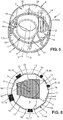
- the figure 1 schematically represents a satellite 1, intended to be placed in orbit around the Earth by means of a launcher.
- the satellite 1 comprises a main body 2 , of generally cylindrical shape extending along a main axis A.
- the adjective “longitudinal” and its variants designate what is parallel to the main axis A; the adjective “transversal” and its variants designate what is included in a plane perpendicular to the main axis A.
- the adjective cylindrical here must be understood in its broad sense as defining a surface drawn by a generating line describing a guiding curve.
- the guide curve may be circular, the main body 2 then having a tubular shape, or polygonal, the main body 2 then having the shape of a prism.
- the main body 2 has an inner wall 3 and an outer wall 4, which define a thickness of the main body 2.
- the adjective “interior” and its variants designate what is turned towards or close to the principal axis A, as opposed to the adjective “outside” and its variants, which designate what is turned to the opposite to or away from the main A axis.
- the main body 2 extends along the main axis A between a so-called lower end surface 5 and a so-called upper end surface 6 .
- the two end surfaces 5, 6 have identical transverse dimensions, making it possible to match the upper end surface 6. a satellite 1 with the lower end surface of another satellite.
- the diameter of the lower end surface is then compatible with the standard spatial diameters, which are those applied to the launchers satellite interface ring: 937 mm, 1194 mm and 1666 mm.
- the diameter of the lower end here refers, for the sake of simplification, to the diameter of the middle circle at the main body 2 between the inner surface 3 and the outer surface 4 at the lower end.
- the diameter of the lower end is then substantially equal to one of the standard values stated above.
- the cylindrical body 2 a cylinder C M average whose guide curve is a circle with a diameter substantially equal to one of the standard values stated above, the average cylinder C M extending over the entire longitudinal dimension of the cylindrical body 2, between the two surfaces 5, 6 end, and included, again over its entire longitudinal dimension, between the inner wall 3 and the outer wall 4.
- At least one of the lower end surface and the upper end surface 6 comprises an interface mechanism for cooperating with another complementary interface mechanism of a satellite interface of a launcher or from another satellite.
- the lower end surface 5 comprises a lower interface mechanism 7 and the upper end surface 6 comprises an upper 8 interface mechanism.
- the interface mechanisms 7, 8 thus allow the satellite 1 to be brought into contact with and to be secured to another satellite or to a satellite interface ring of a launcher.
- the lower interface mechanism 7 is complementary to the upper interface mechanism 8, making it possible for two satellites 1 as shown above to be stacked and to be secured by their interface mechanisms 7, 8. correspondence.
- the mechanisms, respectively 7, 8 of interface are for example linear, that is to say that they extend continuously over the entire circumference of the ends, respectively 5, 6 of the main body 2 .
- the The lower interface mechanism 7 of the satellite 1 comprises an interface ring and the upper interface mechanism 8 of the same satellite 1 also comprises a ring whose shape allows it to fit on the ring of the mechanism 7. lower interface of another satellite.
- the upper interface mechanism 7 and / or the lower interface mechanism 8 comprises a releasable webbing system which makes it possible to grip and maintain two complementary interface mechanisms of two satellites stacked at the same time. by means of a strap.
- the diameter of the rings of the interface mechanisms 7, 8 correspond to the diameter of the average cylinder C M.
- the inner wall 3 defines an interior space 9 , extending between the two surfaces 5, 6 of the main body 2 extreme.
- An interior equipment 10 is in contact with and fixed to the inner wall 3 so as to extend at least partially into the interior space 9.
- Equipment means here any instrument, set of instruments or any electronics of the satellite.
- the interior equipment comprises arms 11 extending transverse to the main axis A, one end of which is in contact with and fixed on the inner wall 3 and the other end is in contact with and fixed on the inside wall. 10 interior equipment.
- the interior equipment comprises the payload of the satellite, i.e. the main equipment necessary for the mission of the satellite 1.
- the payload 13 comprises an optical instrument.
- the interior equipment 10 can then include a mounting plate 12 on which the instrument 13 is rigidly fixed.
- the arms 11 are advantageously fixed on the plate 12 also.
- the plate 12 may comprise one or more optical detectors which preferably have an unobstructed view on at least one face for good radiation cooling. This is why the plate 12 can emerge beyond one of the ends 5, 6 of the main body 2 of the satellite 1, outside the inner space 9.
- the optical instrument 13 is defined in particular by a viewing axis V , virtually defining the direction in which the optical instrument "sees", and by a field of view, defining the entry cone of the light rays in the instrument 13 optical.
- the plate 12 emerges from the inner space 9 by the upper end surface 6.
- the V-axis of sight of the optical instrument 13 is directed towards the lower end surface 5 of the main body 2.
- the main body 2 may, in addition to its force transmission function in a satellite stack, provide other functions, including protection functions of the indoor equipment.
- the main body 2 can serve as a cabinet.
- the fragile elements of the optical instrument 13 are wholly within the interior space. Fragile elements are for example mirrors and their support. The main body 2 then forms a barrier preventing the sun's rays from reaching the fragile elements of the optical instrument.
- the main body 2 may be made of monolithic aluminum, as opposed to a composite material such as Aluminum and Nida Aluminum skin, so as to form a thermal distributor for the outdoor equipment.
- the equipment can be attached directly to the structure, without the use of inserts, unlike composites commonly used in space.
- the main body 2 and the lower and upper interface mechanisms form a monolithic single piece, which can be obtained by machining an aluminum cylinder.
- the transmission capacity of the forces and the rigidity of the assembly are increased, especially if it is associated with a linear interface mechanism 7, 8, as indicated above such as a strap.
- the interior equipment furthermore comprises the electronics associated with the instrument 13.
- the electronics is then for example directly in contact with and fixed on the inside wall 3, in the inner medium 9, so as to It can be mounted in one piece with the instrument 13.
- the instrument 13 and its electronics are generally delivered to the assembly site of the satellite 1 as being an assembly whose connections are tested and certified as functional. . Any disconnection causes the need to re-test the connections.
- the disconnections are avoided.
- the optical axis V of the optical instrument 13 may be confused with the main axis A, in which case the instrument electronics may be distributed around the instrument 13 in the inner space 9.
- the V-axis of sight is preferably parallel to the main axis A but offset, so as to clear a region in the inner space 9 to place the electronics of the instrument.
- the sighting axis V can be inclined with respect to the main axis A.
- the satellite 1 further comprises at least one external equipment 15 in contact with and fixed to the outer wall 4 of the body 2 of the satellite, and thus extending out of the inner space 9.
- the external equipment is selected from electronics such as satellite control electronics 16 , propellant tank 18 , a gyroscopic actuator 17 (also known as CMG for Control Momentum Gyroscope ) or a reaction wheel.
- Other external secondary equipment can also be attached to the outer wall 4, for example, sensors, thrusters to rectify the trajectory of the satellite 1 if necessary or solar panels.
- the outer equipment thus forms a projection transverse to the main axis A on the outer wall 4 on a controlled dimension, corresponding to the place in the launcher.
- the external equipment defines a circle C max , circumscribed to the external equipment, and whose diameter is greater than the diameter of the circle C cir circumscribed to the outer wall 4 of the main body 2 by at least 20%. ( figure 6 ). It is possible to mount larger equipment with possibly additional external secondary structures connected to the main body. Flat solar panels can also be mounted. The diameter of the circle C max may then be 30% or even 40% or 50% greater than that of the circumscribed C cir circle. The practical limit is the diameter of the launcher's cap used.
- the diameter of the average cylinder C M corresponds to a standard diameter
- space is released around the main body 2 when the satellite 1 is placed under the cap of a launcher, making it possible to fix the equipment on the outer wall 4. 15 large bulging exteriors. Congestion under the cap is optimized.
- the outer wall 4 of the body 2 of the satellite may comprise a flat portion, which may extend but not necessarily over the entire dimension along the main axis A so as to form a facet.
- the outer wall 4 is formed of a succession of facets 19 substantially flat, particularly suitable for fixing the external equipment, including electronic.
- the main body 2 offers possibilities for mounting interior equipment and outdoor equipment 15 particularly suited to optimize the space available under the casing in the launcher.
- the satellite 1 thus described can be stacked with other satellites and be placed under the cap of a launcher.
- a first example of stacking is illustrated on the figure 7 .
- four satellites 1 as described above and substantially identical are stacked one above the other by their main body 2.
- the satellites 1 are arranged along the same main axis A, and their interior equipment comprises an optical instrument 13 whose line of sight V is directed towards the lower end surface.
- the four satellites 1 have a main body 2 centered on an average cylinder C M of the same diameter.
- a first satellite 1 is fixed to the launcher by its lower interface mechanism 7. More specifically, the launcher comprises a satellite interface mechanism, typically a ring 20, complementary to the ring of the lower interface mechanism 7 of a first satellite 1. The first satellite 1 is then placed so that its mechanism 7 lower interface is nested on the ring of the launcher interface mechanism. Since the ring of the lower satellite interface mechanism 7 of the first satellite is equal to the diameter of the average cylinder C M , which corresponds to the diameter of the ring 20 of the satellite interface mechanism of the launcher, it is not necessary to place an adapter between the launcher ring 20 and the first satellite 1.
- the launcher also includes a releasable lashing system, the strap of which surrounds the launcher interface mechanism ring 20 and the interface mechanism ring 7. lower of the first satellite. The first satellite 1 is thus secured to the launcher.
- a second satellite 1 is stacked on the first satellite 1, the ring of the lower interface mechanism 7 of the second satellite being fitted on the ring of the upper interface mechanism 8 of the first satellite.
- the upper interface mechanism 8 of the first satellite then comprises a releasable webbing system, the webbing of which engages the ring of the upper interface mechanism 8 of the first satellite 1 and the ring of the lower interface mechanism 7 of the second satellite .
- a third satellite is likewise stacked on the second satellite 1, and a fourth satellite 1 is stacked on the third satellite.
- the fourth, and last, satellite 1 does not include a webbing system.
- the satellites 1 thus stacked have their main axes A confused. Likewise, the V-axis of sight of the optical instruments 13 are all substantially parallel.
- the optical instrument 13 of each satellite 1 being at a distance from the lower end surface of the body 2 of the corresponding satellite, the interior equipment can be astride within the interior space of two satellites 1 stacked.
- the plate 12 emerging through the upper end surface 6 of a lower satellite can be housed in the interior space 9 of the upper satellite, between the optical instrument 13 and the lower end surface 5. from the upper satellite 1.
- the external equipment of the satellites 1, extending transversely from the outer wall 4 of the body 2 of each satellite 1 do not interfere with each other.
- the stacked satellites 1 have their average cylinder C M substantially in continuity with each other and with the satellite interface ring of the launcher, embodying the path through which the forces are transmitted between the satellites.
- the transmission path of the stresses thus extends almost exclusively longitudinally from the satellite interface ring 20 of the launcher to the fourth satellite 1 and passes only through the main bodies 2 of the satellites 1, which allows the stack of have a good mechanical strength.
- the equipment 10 inside each satellite 1 is protected from vibrations and shocks, the forces not being transmitted to them.
- the linear connection provided by the strapping systems also ensures a good distribution of forces over the entire circumference of the main bodies 2 satellites 1.
- the V-axis of sight of each of the optical instruments 13 is oriented towards the satellite interface ring of the launcher.
- This orientation of the V-axis of view allows the satellite to gain compactness. Indeed, especially in the case where the optical instrument 3 is a shooting instrument, by orienting the V-axis of sight towards the satellite interface ring of the launcher, the diameter of the mirrors of the optical instrument 3 can be increased while maintaining the optically necessary dimensional ratios within the instrument 3. However, the larger the diameter of the mirrors, the better the resolution of the optical instrument 3. Moreover, the forces passing through the main body 2, the mounting plate 12 can have its thickness reduced compared to the state of the art, making it possible to increase the dimension along the main axis A of the optical instrument 3 while maintaining a total dimension along the axis A of the satellite adapted to the space in the launcher. Thus, keeping the size of the satellite along the main axis A adapted to the space requirement in the launcher, the performance of the optical instrument 3 is increased.
- each strapping system When the satellites 1 must be dropped into space, each strapping system is open, so as to release the interface mechanisms 7, 8, for example by means of a pyrotechnic device controlled remotely from the Earth, since the launcher or programmed to respect a specific drop sequence.
- the separation between the satellites 1 and the first satellite 1 and the satellite interface ring 20 can be facilitated by means of prestressed elements, of spring type, released when the straps are open.
- each webbing system includes a point of attachment to the body of the corresponding satellite.
- the webbing system of the launcher remains attached to the launcher.
- each satellite 1 may have a system for capturing the webbing system once opened.
- each satellite 1 must ensure the transmission of the control of the opening of the webbing system to the next satellite 1, from the first satellite 1 to the fourth satellite 1. In so doing, the same order repeated n times allows to release n satellite one by one.
- FIG 8 there is shown a second example of a satellite stack 1 according to one embodiment of the invention and a different satellite 21 .
- the different satellite 21 has, in particular, transverse dimensions that do not correspond to those of the surfaces 5, 6 of the ends of the satellite 1 according to the invention.
- the satellite 1 according to the invention is mounted as previously on a satellite interface ring 20 of a launcher, and the different satellite 21 is stacked on the upper end surface 6 of the satellite according to the invention, using an adapter 22 to fill the difference in transverse dimensions.
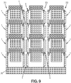
- FIG. 9 there is illustrated a third example of satellite stack 1, substantially identical and according to the invention.
- several columns 23 of satellites 1 can be mounted next to each other on the same satellite interface ring 20 of a launcher.
- the columns 23 may be transversely aligned or arranged in staggered rows on the ring 20.
- An adapter is then mounted between the first satellite of each column 23 and the satellite interface ring 20.
- the number of satellites 1 can be, but not necessarily, the same in each column 23.
- the column arrangement makes it possible, for example, to perform space drop sequences by column 23, the satellites 1 of a column 23 being brought to a determined location from which they can then be separated from each other. Thus, only one trajectory control device per column 23 can be put in place.
- the column arrangement also makes it possible to carry out drop sequences in the space per slice.
- the satellites of the same slice slice are dropped at the same time.
- the next slice can be dropped into a different orbit if the launcher has the ability to re-ignite its propulsion.
Landscapes
- Engineering & Computer Science (AREA)
- Remote Sensing (AREA)
- Aviation & Aerospace Engineering (AREA)
- Physics & Mathematics (AREA)
- Astronomy & Astrophysics (AREA)
- General Physics & Mathematics (AREA)
- Chemical & Material Sciences (AREA)
- Combustion & Propulsion (AREA)
- Radar, Positioning & Navigation (AREA)
- Mechanical Engineering (AREA)
- Evolutionary Computation (AREA)
- Aiming, Guidance, Guns With A Light Source, Armor, Camouflage, And Targets (AREA)
- Telescopes (AREA)
- Photovoltaic Devices (AREA)
- Details Of Aerials (AREA)
Priority Applications (1)
| Application Number | Priority Date | Filing Date | Title |
|---|---|---|---|
| PL16788161T PL3313734T3 (pl) | 2015-10-02 | 2016-09-30 | Satelita z cylindrycznym korpusem głównym, stos zawierający takiego satelitę i zespół do wystrzeliwania dla takiego satelity |
Applications Claiming Priority (2)
| Application Number | Priority Date | Filing Date | Title |
|---|---|---|---|
| FR1559386A FR3041940B1 (fr) | 2015-10-02 | 2015-10-02 | Satellite a corps principal cylindrique, empilement comprenant un tel satellite et ensemble de lancement pour un tel satellite |
| PCT/FR2016/052507 WO2017055770A1 (fr) | 2015-10-02 | 2016-09-30 | Satellite à corps principal cylindrique, empilement comprenant un tel satellite et ensemble de lancement pour un tel satellite |
Publications (2)
| Publication Number | Publication Date |
|---|---|
| EP3313734A1 EP3313734A1 (fr) | 2018-05-02 |
| EP3313734B1 true EP3313734B1 (fr) | 2018-09-26 |
Family
ID=55646666
Family Applications (1)
| Application Number | Title | Priority Date | Filing Date |
|---|---|---|---|
| EP16788161.4A Active EP3313734B1 (fr) | 2015-10-02 | 2016-09-30 | Satellite à corps principal cylindrique, empilement comprenant un tel satellite et ensemble de lancement pour un tel satellite |
Country Status (6)
| Country | Link |
|---|---|
| US (1) | US10689133B2 (pl) |
| EP (1) | EP3313734B1 (pl) |
| ES (1) | ES2690991T3 (pl) |
| FR (1) | FR3041940B1 (pl) |
| PL (1) | PL3313734T3 (pl) |
| WO (1) | WO2017055770A1 (pl) |
Families Citing this family (18)
| Publication number | Priority date | Publication date | Assignee | Title |
|---|---|---|---|---|
| US8915472B2 (en) * | 2012-05-11 | 2014-12-23 | The Boeing Company | Multiple space vehicle launch system |
| US9180984B2 (en) | 2012-05-11 | 2015-11-10 | The Boeing Company | Methods and apparatus for performing propulsion operations using electric propulsion systems |
| FR3041939B1 (fr) * | 2015-10-02 | 2017-10-20 | Airbus Defence & Space Sas | Satellite comprenant un instrument optique de prise de vue |
| US10351268B2 (en) * | 2016-12-08 | 2019-07-16 | The Boeing Company | Systems and methods for deploying spacecraft |
| US11072441B2 (en) * | 2017-03-03 | 2021-07-27 | Northrop Grumman Systems Corporation | Stackable spacecraft |
| US10981679B2 (en) | 2017-08-04 | 2021-04-20 | Rocket Lab Usa, Inc. | Satellite deployer door release mechanism |
| GB2564734B (en) * | 2017-10-18 | 2019-07-10 | Ellinghaus Frank | Panelsat, an agile satellite with fuel free attitude control |
| KR102002306B1 (ko) * | 2018-01-08 | 2019-07-22 | 주식회사 버츄얼랩 | 큐브위성 우주 분리장치 |
| JP2021510650A (ja) * | 2018-01-22 | 2021-04-30 | ルアク・シュヴァイツ・アクチェンゲゼルシャフトRuag Schweiz Ag | ペイロードキャリアアセンブリ |
| IL257491B (en) * | 2018-02-12 | 2021-02-28 | Israel Aerospace Ind Ltd | A space vehicle deploys |
| IL258729B (en) | 2018-04-16 | 2021-12-01 | Israel Aerospace Ind Ltd | Nano-satellite |
| WO2019223984A1 (en) * | 2018-05-24 | 2019-11-28 | The European Union, Represented By The European Commission | Efficient satellite structure concept for single or stacking multiple launches |
| US11560243B2 (en) | 2019-02-22 | 2023-01-24 | Blue Origin, Llc | Spacecraft multifunction connecting mechanisms including interchangeable port opening docking mechanisms, and associated systems and methods |
| US11565628B2 (en) * | 2019-03-29 | 2023-01-31 | Blue Origin, Llc | Spacecraft with increased cargo capacities, and associated systems and methods |
| CN110861785B (zh) * | 2019-11-30 | 2021-06-08 | 中国人民解放军战略支援部队航天工程大学 | 一种光学成像卫星 |
| US11987395B2 (en) | 2021-06-07 | 2024-05-21 | Blue Origin, Llc | Thrusting rails for launch vehicles, and associated systems and methods |
| US12378008B2 (en) | 2023-04-20 | 2025-08-05 | Maxar Space Llc | Solar array spring elements for stacking spacecraft |
| FR3151300B1 (fr) * | 2023-07-17 | 2025-07-18 | Airbus Defence & Space Sas | Procédé et système spatial pour l'éjection d'un empilement de satellites |
Family Cites Families (17)
| Publication number | Priority date | Publication date | Assignee | Title |
|---|---|---|---|---|
| US4009851A (en) * | 1974-12-23 | 1977-03-01 | Rca Corporation | Spacecraft structure |
| ES2046021T3 (es) * | 1990-02-26 | 1994-01-16 | Aerospatiale | Satelite de observacion de tipo geoestacionario con sistema de maniobra de apogeo de ergoles liquidos y con varias toberas. |
| US5169094A (en) * | 1990-02-26 | 1992-12-08 | Aerospatiale Societe Nationale Industrielle | Geostationary earth observation satellite incorporating liquid propellant apogee maneuver system and hollow antennas |
| US5337980A (en) * | 1992-09-21 | 1994-08-16 | General Electric Co. | Spacecraft-to-launch-vehicle transition |
| EP1190948A3 (de) * | 2000-09-22 | 2002-10-16 | Astrium GmbH | Vorrichtung zum Bergen von Raumflugkörpern |
| JP4705172B2 (ja) * | 2005-10-06 | 2011-06-22 | エアドス カサ エスパシオ ソシエダ リミタダ | 打ち上げロケットと衛星を連結および分離する装置 |
| US7840180B2 (en) * | 2006-12-22 | 2010-11-23 | The Boeing Company | Molniya orbit satellite systems, apparatus, and methods |
| US8016240B2 (en) * | 2007-03-29 | 2011-09-13 | The Boeing Company | Satellites and satellite fleet implementation methods and apparatus |
| FR2932576B1 (fr) * | 2008-06-13 | 2013-02-15 | Thales Sa | Ensemble multi-instruments embarque ultra-stable. |
| FR2939912B1 (fr) * | 2008-12-12 | 2011-04-15 | Thales Sa | Ensemble de support d'un miroir secondaire d'un engin spatial d'observation de haute stabilite et a faible inertie mecanique |
| FR2959490B1 (fr) * | 2010-04-28 | 2012-07-13 | Astrium Sas | Satellite a structure simplifiee, allegee et economique, et son procede de mise en oeuvre |
| EP4462601A3 (en) * | 2010-12-15 | 2025-02-19 | Planet Labs PBC | Integrated antenna system for imaging microsatellites |
| EP2489593A1 (en) * | 2011-02-21 | 2012-08-22 | European Space Agency | Earth observation satellite, satellite system, and launching system for launching satellites |
| US8789797B2 (en) * | 2012-02-23 | 2014-07-29 | Alliant Techsystems Inc. | Payload adapters including antenna assemblies, satellite assemblies and related systems and methods |
| US8939409B2 (en) | 2012-05-07 | 2015-01-27 | The Johns Hopkins University | Adaptor system for deploying small satellites |
| US9027889B2 (en) * | 2013-02-28 | 2015-05-12 | The Boeing Comapny | Modular core structure for dual-manifest spacecraft launch |
| FR3041939B1 (fr) * | 2015-10-02 | 2017-10-20 | Airbus Defence & Space Sas | Satellite comprenant un instrument optique de prise de vue |
-
2015
- 2015-10-02 FR FR1559386A patent/FR3041940B1/fr not_active Expired - Fee Related
-
2016
- 2016-09-30 WO PCT/FR2016/052507 patent/WO2017055770A1/fr not_active Ceased
- 2016-09-30 US US15/764,678 patent/US10689133B2/en active Active
- 2016-09-30 ES ES16788161.4T patent/ES2690991T3/es active Active
- 2016-09-30 EP EP16788161.4A patent/EP3313734B1/fr active Active
- 2016-09-30 PL PL16788161T patent/PL3313734T3/pl unknown
Non-Patent Citations (1)
| Title |
|---|
| None * |
Also Published As
| Publication number | Publication date |
|---|---|
| US20180265227A1 (en) | 2018-09-20 |
| ES2690991T3 (es) | 2018-11-23 |
| EP3313734A1 (fr) | 2018-05-02 |
| FR3041940A1 (fr) | 2017-04-07 |
| WO2017055770A1 (fr) | 2017-04-06 |
| PL3313734T3 (pl) | 2019-01-31 |
| FR3041940B1 (fr) | 2018-07-13 |
| US10689133B2 (en) | 2020-06-23 |
Similar Documents
| Publication | Publication Date | Title |
|---|---|---|
| EP3313734B1 (fr) | Satellite à corps principal cylindrique, empilement comprenant un tel satellite et ensemble de lancement pour un tel satellite | |
| EP3259190B1 (fr) | Véhicule spatial comprenant des poteaux pour former un empilement, empilement comprenant au moins deux tels véhicules placés dans un lanceur et procédé de largage des véhicules | |
| EP3174794B2 (fr) | Satellite comprenant un instrument optique de prise de vue | |
| EP2563670B1 (fr) | Satellite a structure simplifiee, allegee et economique, et son procede de mise en oeuvre | |
| EP2716549B1 (fr) | Satellite à modules de charge utile déployables | |
| EP1247741B1 (fr) | Radiateur déployable pour engin spatial | |
| FR3004166A1 (fr) | Systeme de satellites comportant deux satellites fixes l'un a l'autre et procede pour leur mise en orbite | |
| EP2514674B1 (fr) | Dispositif de protection d'un instrument optique d'un satellite | |
| EP0571256B1 (fr) | Satellite géodésique de faible masse à rétroréflecteur à correction d'aberration de vitesse | |
| FR2746365A1 (fr) | Perfectionnements aux satellites d'observation ou de telecommunication | |
| FR2907423A1 (fr) | Gyrodyne et son dispositif de montage | |
| EP0445011B1 (fr) | Satellite d'observation de type géostationnaire à système de manoeuvre d'apogée à ergols liquides et à plusieurs tuyères | |
| EP3027512B1 (fr) | Procede et dispositif de liaison et de separation de deux elements avec des moyens de liaison et de separation melanges | |
| EP2062328B1 (fr) | Instrument d'acquisition spatiale a reflecteur(s) deployable(s) et a compacite elevee | |
| WO2024156962A1 (fr) | Structure de fixation d'un équipement sur un engin, tel qu'un nanosatellite | |
| EP4590584A1 (fr) | Empilement d'engins spatiaux | |
| FR3023264A1 (fr) | Satellite a maitre couple variable | |
| FR3063281A1 (fr) | Procede et dispositif de liaison et de separation lineaire de deux elements colles | |
| FR2664562A1 (fr) | Satellite de type geostationnaire a systeme de manóoeuvre d'apogee a ergols liquides et a plusieurs tuyeres. | |
| FR2829662A1 (fr) | Suspension pour module electronique devant fonctionner durant et apres impacts severes | |
| FR2746364A1 (fr) | Satellite d'observation radar ou de telecommunication | |
| FR2965609A1 (fr) | Systeme d'arme lance-munition et analogue, a prolongateur tubulaire |
Legal Events
| Date | Code | Title | Description |
|---|---|---|---|
| STAA | Information on the status of an ep patent application or granted ep patent |
Free format text: STATUS: UNKNOWN |
|
| STAA | Information on the status of an ep patent application or granted ep patent |
Free format text: STATUS: THE INTERNATIONAL PUBLICATION HAS BEEN MADE |
|
| PUAI | Public reference made under article 153(3) epc to a published international application that has entered the european phase |
Free format text: ORIGINAL CODE: 0009012 |
|
| STAA | Information on the status of an ep patent application or granted ep patent |
Free format text: STATUS: REQUEST FOR EXAMINATION WAS MADE |
|
| 17P | Request for examination filed |
Effective date: 20180126 |
|
| AK | Designated contracting states |
Kind code of ref document: A1 Designated state(s): AL AT BE BG CH CY CZ DE DK EE ES FI FR GB GR HR HU IE IS IT LI LT LU LV MC MK MT NL NO PL PT RO RS SE SI SK SM TR |
|
| AX | Request for extension of the european patent |
Extension state: BA ME |
|
| GRAP | Despatch of communication of intention to grant a patent |
Free format text: ORIGINAL CODE: EPIDOSNIGR1 |
|
| STAA | Information on the status of an ep patent application or granted ep patent |
Free format text: STATUS: GRANT OF PATENT IS INTENDED |
|
| INTG | Intention to grant announced |
Effective date: 20180515 |
|
| GRAS | Grant fee paid |
Free format text: ORIGINAL CODE: EPIDOSNIGR3 |
|
| GRAA | (expected) grant |
Free format text: ORIGINAL CODE: 0009210 |
|
| STAA | Information on the status of an ep patent application or granted ep patent |
Free format text: STATUS: THE PATENT HAS BEEN GRANTED |
|
| DAV | Request for validation of the european patent (deleted) | ||
| DAX | Request for extension of the european patent (deleted) | ||
| RAP1 | Party data changed (applicant data changed or rights of an application transferred) |
Owner name: AIRBUS DEFENCE AND SPACE SAS |
|
| REG | Reference to a national code |
Ref country code: FR Ref legal event code: PLFP Year of fee payment: 3 |
|
| AK | Designated contracting states |
Kind code of ref document: B1 Designated state(s): AL AT BE BG CH CY CZ DE DK EE ES FI FR GB GR HR HU IE IS IT LI LT LU LV MC MK MT NL NO PL PT RO RS SE SI SK SM TR |
|
| REG | Reference to a national code |
Ref country code: GB Ref legal event code: FG4D Free format text: NOT ENGLISH |
|
| REG | Reference to a national code |
Ref country code: CH Ref legal event code: EP |
|
| REG | Reference to a national code |
Ref country code: AT Ref legal event code: REF Ref document number: 1045712 Country of ref document: AT Kind code of ref document: T Effective date: 20181015 |
|
| REG | Reference to a national code |
Ref country code: IE Ref legal event code: FG4D Free format text: LANGUAGE OF EP DOCUMENT: FRENCH |
|
| REG | Reference to a national code |
Ref country code: DE Ref legal event code: R096 Ref document number: 602016006101 Country of ref document: DE |
|
| REG | Reference to a national code |
Ref country code: ES Ref legal event code: FG2A Ref document number: 2690991 Country of ref document: ES Kind code of ref document: T3 Effective date: 20181123 |
|
| REG | Reference to a national code |
Ref country code: NL Ref legal event code: MP Effective date: 20180926 |
|
| PG25 | Lapsed in a contracting state [announced via postgrant information from national office to epo] |
Ref country code: NO Free format text: LAPSE BECAUSE OF FAILURE TO SUBMIT A TRANSLATION OF THE DESCRIPTION OR TO PAY THE FEE WITHIN THE PRESCRIBED TIME-LIMIT Effective date: 20181226 Ref country code: GR Free format text: LAPSE BECAUSE OF FAILURE TO SUBMIT A TRANSLATION OF THE DESCRIPTION OR TO PAY THE FEE WITHIN THE PRESCRIBED TIME-LIMIT Effective date: 20181227 Ref country code: FI Free format text: LAPSE BECAUSE OF FAILURE TO SUBMIT A TRANSLATION OF THE DESCRIPTION OR TO PAY THE FEE WITHIN THE PRESCRIBED TIME-LIMIT Effective date: 20180926 Ref country code: BG Free format text: LAPSE BECAUSE OF FAILURE TO SUBMIT A TRANSLATION OF THE DESCRIPTION OR TO PAY THE FEE WITHIN THE PRESCRIBED TIME-LIMIT Effective date: 20181226 Ref country code: LT Free format text: LAPSE BECAUSE OF FAILURE TO SUBMIT A TRANSLATION OF THE DESCRIPTION OR TO PAY THE FEE WITHIN THE PRESCRIBED TIME-LIMIT Effective date: 20180926 Ref country code: RS Free format text: LAPSE BECAUSE OF FAILURE TO SUBMIT A TRANSLATION OF THE DESCRIPTION OR TO PAY THE FEE WITHIN THE PRESCRIBED TIME-LIMIT Effective date: 20180926 |
|
| REG | Reference to a national code |
Ref country code: LT Ref legal event code: MG4D |
|
| PG25 | Lapsed in a contracting state [announced via postgrant information from national office to epo] |
Ref country code: AL Free format text: LAPSE BECAUSE OF FAILURE TO SUBMIT A TRANSLATION OF THE DESCRIPTION OR TO PAY THE FEE WITHIN THE PRESCRIBED TIME-LIMIT Effective date: 20180926 Ref country code: HR Free format text: LAPSE BECAUSE OF FAILURE TO SUBMIT A TRANSLATION OF THE DESCRIPTION OR TO PAY THE FEE WITHIN THE PRESCRIBED TIME-LIMIT Effective date: 20180926 Ref country code: LV Free format text: LAPSE BECAUSE OF FAILURE TO SUBMIT A TRANSLATION OF THE DESCRIPTION OR TO PAY THE FEE WITHIN THE PRESCRIBED TIME-LIMIT Effective date: 20180926 |
|
| REG | Reference to a national code |
Ref country code: AT Ref legal event code: MK05 Ref document number: 1045712 Country of ref document: AT Kind code of ref document: T Effective date: 20180926 |
|
| PG25 | Lapsed in a contracting state [announced via postgrant information from national office to epo] |
Ref country code: NL Free format text: LAPSE BECAUSE OF FAILURE TO SUBMIT A TRANSLATION OF THE DESCRIPTION OR TO PAY THE FEE WITHIN THE PRESCRIBED TIME-LIMIT Effective date: 20180926 Ref country code: IS Free format text: LAPSE BECAUSE OF FAILURE TO SUBMIT A TRANSLATION OF THE DESCRIPTION OR TO PAY THE FEE WITHIN THE PRESCRIBED TIME-LIMIT Effective date: 20190126 Ref country code: AT Free format text: LAPSE BECAUSE OF FAILURE TO SUBMIT A TRANSLATION OF THE DESCRIPTION OR TO PAY THE FEE WITHIN THE PRESCRIBED TIME-LIMIT Effective date: 20180926 Ref country code: EE Free format text: LAPSE BECAUSE OF FAILURE TO SUBMIT A TRANSLATION OF THE DESCRIPTION OR TO PAY THE FEE WITHIN THE PRESCRIBED TIME-LIMIT Effective date: 20180926 Ref country code: CZ Free format text: LAPSE BECAUSE OF FAILURE TO SUBMIT A TRANSLATION OF THE DESCRIPTION OR TO PAY THE FEE WITHIN THE PRESCRIBED TIME-LIMIT Effective date: 20180926 Ref country code: RO Free format text: LAPSE BECAUSE OF FAILURE TO SUBMIT A TRANSLATION OF THE DESCRIPTION OR TO PAY THE FEE WITHIN THE PRESCRIBED TIME-LIMIT Effective date: 20180926 |
|
| PG25 | Lapsed in a contracting state [announced via postgrant information from national office to epo] |
Ref country code: SM Free format text: LAPSE BECAUSE OF FAILURE TO SUBMIT A TRANSLATION OF THE DESCRIPTION OR TO PAY THE FEE WITHIN THE PRESCRIBED TIME-LIMIT Effective date: 20180926 Ref country code: PT Free format text: LAPSE BECAUSE OF FAILURE TO SUBMIT A TRANSLATION OF THE DESCRIPTION OR TO PAY THE FEE WITHIN THE PRESCRIBED TIME-LIMIT Effective date: 20190126 Ref country code: SK Free format text: LAPSE BECAUSE OF FAILURE TO SUBMIT A TRANSLATION OF THE DESCRIPTION OR TO PAY THE FEE WITHIN THE PRESCRIBED TIME-LIMIT Effective date: 20180926 |
|
| REG | Reference to a national code |
Ref country code: IE Ref legal event code: MM4A |
|
| REG | Reference to a national code |
Ref country code: DE Ref legal event code: R097 Ref document number: 602016006101 Country of ref document: DE |
|
| PG25 | Lapsed in a contracting state [announced via postgrant information from national office to epo] |
Ref country code: IE Free format text: LAPSE BECAUSE OF NON-PAYMENT OF DUE FEES Effective date: 20180930 Ref country code: DK Free format text: LAPSE BECAUSE OF FAILURE TO SUBMIT A TRANSLATION OF THE DESCRIPTION OR TO PAY THE FEE WITHIN THE PRESCRIBED TIME-LIMIT Effective date: 20180926 Ref country code: MC Free format text: LAPSE BECAUSE OF FAILURE TO SUBMIT A TRANSLATION OF THE DESCRIPTION OR TO PAY THE FEE WITHIN THE PRESCRIBED TIME-LIMIT Effective date: 20180926 |
|
| PLBE | No opposition filed within time limit |
Free format text: ORIGINAL CODE: 0009261 |
|
| STAA | Information on the status of an ep patent application or granted ep patent |
Free format text: STATUS: NO OPPOSITION FILED WITHIN TIME LIMIT |
|
| 26N | No opposition filed |
Effective date: 20190627 |
|
| PG25 | Lapsed in a contracting state [announced via postgrant information from national office to epo] |
Ref country code: MT Free format text: LAPSE BECAUSE OF FAILURE TO SUBMIT A TRANSLATION OF THE DESCRIPTION OR TO PAY THE FEE WITHIN THE PRESCRIBED TIME-LIMIT Effective date: 20180926 |
|
| PG25 | Lapsed in a contracting state [announced via postgrant information from national office to epo] |
Ref country code: TR Free format text: LAPSE BECAUSE OF FAILURE TO SUBMIT A TRANSLATION OF THE DESCRIPTION OR TO PAY THE FEE WITHIN THE PRESCRIBED TIME-LIMIT Effective date: 20180926 |
|
| REG | Reference to a national code |
Ref country code: CH Ref legal event code: PL |
|
| PG25 | Lapsed in a contracting state [announced via postgrant information from national office to epo] |
Ref country code: CY Free format text: LAPSE BECAUSE OF FAILURE TO SUBMIT A TRANSLATION OF THE DESCRIPTION OR TO PAY THE FEE WITHIN THE PRESCRIBED TIME-LIMIT Effective date: 20180926 Ref country code: SE Free format text: LAPSE BECAUSE OF FAILURE TO SUBMIT A TRANSLATION OF THE DESCRIPTION OR TO PAY THE FEE WITHIN THE PRESCRIBED TIME-LIMIT Effective date: 20180926 Ref country code: MK Free format text: LAPSE BECAUSE OF NON-PAYMENT OF DUE FEES Effective date: 20180926 Ref country code: HU Free format text: LAPSE BECAUSE OF FAILURE TO SUBMIT A TRANSLATION OF THE DESCRIPTION OR TO PAY THE FEE WITHIN THE PRESCRIBED TIME-LIMIT; INVALID AB INITIO Effective date: 20160930 |
|
| PG25 | Lapsed in a contracting state [announced via postgrant information from national office to epo] |
Ref country code: CH Free format text: LAPSE BECAUSE OF NON-PAYMENT OF DUE FEES Effective date: 20190930 Ref country code: LI Free format text: LAPSE BECAUSE OF NON-PAYMENT OF DUE FEES Effective date: 20190930 |
|
| PG25 | Lapsed in a contracting state [announced via postgrant information from national office to epo] |
Ref country code: SI Free format text: LAPSE BECAUSE OF NON-PAYMENT OF DUE FEES Effective date: 20180930 |
|
| PGFP | Annual fee paid to national office [announced via postgrant information from national office to epo] |
Ref country code: FR Payment date: 20220921 Year of fee payment: 7 |
|
| PG25 | Lapsed in a contracting state [announced via postgrant information from national office to epo] |
Ref country code: FR Free format text: LAPSE BECAUSE OF NON-PAYMENT OF DUE FEES Effective date: 20230930 |
|
| PGFP | Annual fee paid to national office [announced via postgrant information from national office to epo] |
Ref country code: DE Payment date: 20250919 Year of fee payment: 10 |
|
| PGFP | Annual fee paid to national office [announced via postgrant information from national office to epo] |
Ref country code: PL Payment date: 20250826 Year of fee payment: 10 Ref country code: IT Payment date: 20250923 Year of fee payment: 10 Ref country code: LU Payment date: 20250919 Year of fee payment: 10 |
|
| PGFP | Annual fee paid to national office [announced via postgrant information from national office to epo] |
Ref country code: BE Payment date: 20250918 Year of fee payment: 10 Ref country code: GB Payment date: 20250919 Year of fee payment: 10 |
|
| PGFP | Annual fee paid to national office [announced via postgrant information from national office to epo] |
Ref country code: ES Payment date: 20251028 Year of fee payment: 10 |