EP3312974A1 - Strahlkühlungssystem mit radialem gegenstrom - Google Patents
Strahlkühlungssystem mit radialem gegenstrom Download PDFInfo
- Publication number
- EP3312974A1 EP3312974A1 EP17197337.3A EP17197337A EP3312974A1 EP 3312974 A1 EP3312974 A1 EP 3312974A1 EP 17197337 A EP17197337 A EP 17197337A EP 3312974 A1 EP3312974 A1 EP 3312974A1
- Authority
- EP
- European Patent Office
- Prior art keywords
- radial
- counter flow
- cooling system
- axial
- radial counter
- Prior art date
- Legal status (The legal status is an assumption and is not a legal conclusion. Google has not performed a legal analysis and makes no representation as to the accuracy of the status listed.)
- Granted
Links
- 238000001816 cooling Methods 0.000 title claims abstract description 58
- 238000004891 communication Methods 0.000 claims abstract description 16
- 239000007789 gas Substances 0.000 claims description 45
- 239000000112 cooling gas Substances 0.000 claims description 18
- 239000004020 conductor Substances 0.000 claims description 6
- 238000000034 method Methods 0.000 claims description 3
- 238000010586 diagram Methods 0.000 description 10
- 238000004804 winding Methods 0.000 description 3
- 238000004519 manufacturing process Methods 0.000 description 2
- 238000002788 crimping Methods 0.000 description 1
- 230000004907 flux Effects 0.000 description 1
- 238000009413 insulation Methods 0.000 description 1
Images


Classifications
-
- H—ELECTRICITY
- H02—GENERATION; CONVERSION OR DISTRIBUTION OF ELECTRIC POWER
- H02K—DYNAMO-ELECTRIC MACHINES
- H02K9/00—Arrangements for cooling or ventilating
- H02K9/14—Arrangements for cooling or ventilating wherein gaseous cooling medium circulates between the machine casing and a surrounding mantle
- H02K9/16—Arrangements for cooling or ventilating wherein gaseous cooling medium circulates between the machine casing and a surrounding mantle wherein the cooling medium circulates through ducts or tubes within the casing
-
- H—ELECTRICITY
- H02—GENERATION; CONVERSION OR DISTRIBUTION OF ELECTRIC POWER
- H02K—DYNAMO-ELECTRIC MACHINES
- H02K1/00—Details of the magnetic circuit
- H02K1/06—Details of the magnetic circuit characterised by the shape, form or construction
- H02K1/22—Rotating parts of the magnetic circuit
- H02K1/32—Rotating parts of the magnetic circuit with channels or ducts for flow of cooling medium
-
- H—ELECTRICITY
- H02—GENERATION; CONVERSION OR DISTRIBUTION OF ELECTRIC POWER
- H02K—DYNAMO-ELECTRIC MACHINES
- H02K3/00—Details of windings
- H02K3/04—Windings characterised by the conductor shape, form or construction, e.g. with bar conductors
- H02K3/24—Windings characterised by the conductor shape, form or construction, e.g. with bar conductors with channels or ducts for cooling medium between the conductors
-
- H—ELECTRICITY
- H02—GENERATION; CONVERSION OR DISTRIBUTION OF ELECTRIC POWER
- H02K—DYNAMO-ELECTRIC MACHINES
- H02K9/00—Arrangements for cooling or ventilating
- H02K9/02—Arrangements for cooling or ventilating by ambient air flowing through the machine
- H02K9/04—Arrangements for cooling or ventilating by ambient air flowing through the machine having means for generating a flow of cooling medium
-
- H—ELECTRICITY
- H02—GENERATION; CONVERSION OR DISTRIBUTION OF ELECTRIC POWER
- H02K—DYNAMO-ELECTRIC MACHINES
- H02K9/00—Arrangements for cooling or ventilating
- H02K9/10—Arrangements for cooling or ventilating by gaseous cooling medium flowing in closed circuit, a part of which is external to the machine casing
Definitions
- the present application relates generally to dynamoelectric machines such as generators used in the production of electrical power and more particularly relates to improved cooling of dynamoelectric machine rotors using a radial-axial jet cooling system.
- large turbine driven generators used in the production of electrical power and the like may include a rotor and a stator.
- the rotor serves as a source of magnetic lines of flux produced by a coil wound thereon.
- the rotor rotates within the stator.
- the stator may include a number of conductors in which an alternating current may be induced therein. Specifically, this rotation generates a magnetic field in a narrow gas gap between the rotor and the stator.
- the overall power output of a generator may be limited by the inability to provide additional current due to a buildup of heat in the stator components and/or the rotor components. This generated heat should be dissipated to a cooling gas or other medium so as to avoid insulation failure and the like. Moreover, the lack of adequate cooling may result in a rotor winding hot spot. For example, a typical rotor winding hot spot may be found about the center line of the rotor. Specifically, many rotor designs may have a non-actively cooled centering pin positioned along the centering line. Reducing hot spot temperatures about the centering pin and elsewhere thus may increase the utilization of the rotor windings and the overall power output of the generator.
- the present application thus provides a radial counter flow jet gas cooling system for a rotor of a dynamoelectric machine.
- the radial counter flow jet gas cooling system may include a centering pin, a number of axial inlet ducts, a number of radial outlet ducts in communication with the axial inlet ducts, an axial subslot positioned about the axial inlet ducts, and a radial counter flow duct in communication with the axial subslot and extending along the centering pin to provide cooling thereto.
- the present application and the resultant patent further provide a method of cooling a rotor of a dynamoelectric machine.
- the method may include the steps of flowing cooling gas through a number of axial inlet ducts and a number of radial outlet ducts to cool a number of conductor bars, flowing cooling gas through an axial subslot and a radial counter flow duct to cool a centering pin, and flowing the cooling gas from the radial counter flow duct into the axial inlet ducts and one or more of the radial outlet ducts.
- the present application and the resultant patent further provide a rotor of a dynamoelectric machine.
- the rotor may include a centering pin, a number of axial inlet ducts with one or more flow separators, a number of radial outlet ducts in communication with the axial inlet ducts, an axial subslot positioned about the axial inlet ducts, and a radial counter flow duct in communication with the axial subslot, extending along the centering pin, and in communication with the axial inlet ducts.
- Fig. 1 is a schematic diagram of an example of a portion of a dynamoelectric machine 100. Specifically, a portion of a rotor 20 is shown.
- the rotor 20 may include a number of conductor bars 30 axially positioned about a centering pin 40.
- the rotor 20 may include a gas cooling system 50.
- the gas cooling system 50 may include a number of axial inlet ducts 60. In this example, ten (10) axial inlet ducts 60 are shown with a first axial inlet duct 61, a second axial inlet duct 62, a third axial inlet duct 63, ...
- Each pair of the axial inlet ducts 60 may lead to a radial outlet duct 80.
- a first radial outlet duct 81 that extends from the first axial inlet duct 61 and the second axial inlet duct 62
- a second radial outlet duct 82 that extends from the third axial inlet duct 63 and the fourth axial inlet duct 64
- a fifth radial outlet duct 85 that extends from the ninth axial inlet duct 69 and the tenth axial inlet duct 70.
- Any number of the axial inlet ducts 60 and the radial inlet ducts 80 may be used.
- the axial inlet ducts 60 may include one or more flow separators 90, (i.e., a blocker or a crimping) about each radial outlet duct 80 or elsewhere so as to block the flow of gas 55.
- the flow of gas 55 may extend into the axial inlet ducts 60 and out via the radial outlet ducts 80 towards the air gap.
- only the first axial inlet duct 61 and the second axial inlet duct 62 may extend about the centering pin 40.
- the remaining length of the centering pin 40 may not be actively cooled and hence may lead to a hot spot and the like.
- the rotor 20 described herein is for the purpose of example only. Many other and different types of rotors and rotor components may be known.
- Fig. 2 is a schematic diagram of an example of a portion of a dynamoelectric machine 100 as may be described herein. Specifically, a portion of a rotor 110 is shown.
- the rotor 110 may include the conductor bars 30 positioned about the centering pin 40.
- the rotor 110 also may include a radial counter flow jet gas cooling system 120.
- the radial counter flow jet gas cooling system 120 may include the axial inlet ducts 60 and the radial outlet ducts 80. Any number of the axial inlet ducts 60 and the radial outlet ducts 80 may be used herein in any suitable size, shape, or configuration.
- the radial counter flow jet gas cooling system 120 may include a radial counter flow jet 130.
- the radial counter flow jet 130 may include an axial subslot 140.
- the axial subslot 140 may be positioned beneath the axial inlet ducts 60.
- the axial subslot 140 may lead to a radial counter flow duct 150.
- the radial counter flow duct 150 may be in communication with the axial inlet ducts 60 and the first radial outlet duct 81.
- the axial subslot 140 may be about half the size of the existing axial inlet ducts 60 although the axial subslot 140 and the radial counter flow duct 150 may have any suitable size, shape, or configuration. Other components and other configurations may be used herein.
- the radial counter flow jet gas cooling system 120 may provide the cooling gas 55 close to the centering pin 40 via the axial subslot 140 and the radial counter flow duct 150 of the radial counter flow jet 130.
- the cooling gas 55 may extend through the radial counter flow duct 150 along the length of the centering pin 40 to provide cooling thereto.
- the cooling gas 55 then may be exhausted in a counter flow direction along the axial inlet ducts 60 and out via the first radial outlet duct 81 or otherwise.
- Other components and configurations also may be used herein.
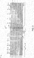
- Fig. 3 shows an alternative embodiment of a radial counter flow jet gas cooling system 160.
- the gas cooling system 160 may include a radial cross over cooling jet 170.
- the radial cross over cooling jet 170 may include the axial subslot 140.
- the axial subslot 140 may lead to a radial cross over duct 180.
- the radial cross over duct 180 may be in communication with a number of cross over slots 190 positioned within the centering pin 40.
- the cooling gas 55 thus may pass through the axial subslot 140, into the radial cross over duct 180, and cross over the centering pin 40 via the cross over slots 190.
- the cooling gas 55 then may exit via the axial inlet ducts 60 and the radial outlet ducts 80 on the other side of the centering pin 40.
- the radial cross over duct 180 and the cross over slots 190 may have any suitable size, shape, or configuration. Other components and other configurations also may be used herein.
- Fig. 4 shows a further alternative embodiment of a radial counter flow jet gas cooling system 200 as may be described herein.
- the radial counter flow jet gas cooling system 200 may include a combined radial counter flow and cross over cooling jet 210.
- the combination radial counter flow and cross over flow cooling jet 210 may include the axial subslot 140 leading to a radial combination duct 220.
- the centering pin 40 may have a number of the cross over slots 190 therein while a number of the axial inlet ducts 60 may have a flow separator 90 therein.
- the cooling gas 55 may enter the radial combination duct 220 with a portion of the cooling gas 55 crossing over the centering pin 40 in one direction and a portion of the cooling gas 55 extending in a cross flow direction back towards the first radial outlet duct 81 or otherwise.
- the radial combination duct 220 and the cross over slots 190 may have any suitable size, shape, or configuration. Other components and configurations also may be used herein.
- Figs. 5 and 6 show a further embodiment of a radial counter flow jet gas cooling system 230 as may be described herein.
- the radial counter flow jet gas cooling system 230 may include one or more inclined radial counter flow jets 240.
- the inclined radial counter flow jets 240 may include the axial subslot 140.
- the axial subslot 140 may lead to one or more inclined radial counter flow ducts 250.
- the inclined radial counter flow ducts 250 may be inclined towards the centering pin 40 in the direction of the gas gap. As a result, more of the cooling gas 55 may be directed towards that end of the centering pin 40.
- Fig. 5 shows the use of a single inclined radial counter flow duct 250.
- Fig. 6 shows the use of two or more inclined radial counter flow ducts 250. Any number of the inclined radial counter flow ducts 250 may be used herein in any suitable size, shape, or configuration. Other components and other configurations may be used herein.
- Fig. 7 shows a further embodiment of a radial counter flow jet gas cooling system 260 as may be described herein.
- the radial counter flow jet gas cooling system 260 may include a dedicated radial counter flow jet 270.
- the dedicated radial counter flow jet 270 may use the axial subslot 140 and the radial counter flow duct 150.
- the dedicated radial counter flow jet 270 also may include a dedicated radial outlet duct 280.
- the dedicated radial outlet duct 280 may provide an additional exit path for the cooling gas 55.
- the dedicated radial outlet duct 280 may have any suitable size, shape, or configuration. Other components and other configurations also may be used herein.
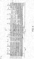
- Fig. 8 shows a further embodiment of a radial counter flow jet gas cooling system 290 as may be described herein.
- the axial subslot 140 ends about the radial counter flow duct 150 on either side of the centering pin 40.
- the radial counter flow jet gas cooling system 290 may use a continuous axial subslot 300.
- the continuous axial subslot 300 may extend through a centering pin subslot aperture 310.
- the subslot aperture 310 thus allows the cooling gas 55 to extend on either side of the centering pin 400.
- the continuous axial subslot 300 may have any suitable size, shape, or configuration. Other components and other configurations may be used herein.
- the radial counter flow jet gas cooling systems described herein thus may significantly reduce the temperature about the centering pin 40 so as to reduce or eliminate hot spots thereabout. Such active cooling may reduce the hot spots with an optimum cooling flow thereto.
- Each of the radial counter flow jet gas cooling systems described above may be used as shown and/or in combination with the other embodiments. It should be apparent that the foregoing relates only to certain embodiments of the present application.
Applications Claiming Priority (1)
| Application Number | Priority Date | Filing Date | Title |
|---|---|---|---|
| US15/298,453 US10326335B2 (en) | 2016-10-20 | 2016-10-20 | Radial counter flow jet cooling system |
Publications (2)
| Publication Number | Publication Date |
|---|---|
| EP3312974A1 true EP3312974A1 (de) | 2018-04-25 |
| EP3312974B1 EP3312974B1 (de) | 2021-09-01 |
Family
ID=60143620
Family Applications (1)
| Application Number | Title | Priority Date | Filing Date |
|---|---|---|---|
| EP17197337.3A Active EP3312974B1 (de) | 2016-10-20 | 2017-10-19 | Strahlkühlungssystem mit radialem gegenstrom |
Country Status (4)
| Country | Link |
|---|---|
| US (2) | US10326335B2 (de) |
| EP (1) | EP3312974B1 (de) |
| JP (1) | JP7106260B2 (de) |
| CN (1) | CN107968506B (de) |
Families Citing this family (2)
| Publication number | Priority date | Publication date | Assignee | Title |
|---|---|---|---|---|
| US10326335B2 (en) * | 2016-10-20 | 2019-06-18 | General Electric Technology Gmbh | Radial counter flow jet cooling system |
| EP4106152A1 (de) | 2021-06-17 | 2022-12-21 | General Electric Company | Magnetische masse für einen rotor, zugehöriger rotor und rotierende elektrische maschine |
Citations (5)
| Publication number | Priority date | Publication date | Assignee | Title |
|---|---|---|---|---|
| JPS50146005U (de) * | 1974-05-21 | 1975-12-03 | ||
| US4634910A (en) * | 1984-08-27 | 1987-01-06 | Bbc Brown, Boveri & Company Limited | Rotor of an electrical machine having a directly cooled rotor winding |
| GB2399231A (en) * | 2003-03-07 | 2004-09-08 | Alstom | Multi-path cooling of a turbo-generator rotor winding |
| US20100096937A1 (en) * | 2008-10-21 | 2010-04-22 | General Electric Company | Heat transfer enhancement of dynamoelectric machine rotors |
| US20150162804A1 (en) * | 2013-12-05 | 2015-06-11 | General Electric Company | Rotor with cooling manifolds |
Family Cites Families (14)
| Publication number | Priority date | Publication date | Assignee | Title |
|---|---|---|---|---|
| BE534929A (de) * | 1954-01-19 | |||
| JPS56118564U (de) * | 1980-02-12 | 1981-09-10 | ||
| JPS634140U (de) * | 1986-06-23 | 1988-01-12 | ||
| DE4337628A1 (de) * | 1993-11-04 | 1995-05-11 | Abb Management Ag | Rotor eines Turbogenerators mit direkter Gaskühlung der Erregerwicklung |
| GB2393584B (en) * | 2002-09-26 | 2006-06-21 | Alstom | Gas-cooled generator |
| US7462962B2 (en) | 2005-06-13 | 2008-12-09 | General Electric Company | Cooling system for an electrical machine with center rotor cooling dusts |
| ES2379191T3 (es) | 2006-02-17 | 2012-04-23 | Ansaldo Energia S.P.A. | Rotor ventilado de un turbogenerador de alta potencia para la producción de electricidad |
| EP2120314A1 (de) | 2008-05-16 | 2009-11-18 | Siemens Aktiengesellschaft | Rotorkühlung für eine dynamoelektrische Maschine |
| US7816825B2 (en) * | 2008-07-23 | 2010-10-19 | General Electric Company | Heat transfer enhancement of ventilation chimneys for dynamoelectric machine rotors |
| US8049379B2 (en) * | 2009-04-23 | 2011-11-01 | General Electric Company | Dynamoelectric machine rotors having enhanced heat transfer and method therefor |
| US7893576B2 (en) | 2009-05-05 | 2011-02-22 | General Electric Company | Generator coil cooling baffles |
| US20120101768A1 (en) | 2010-10-26 | 2012-04-26 | General Electric Company | Diagnosis of stator thermal anomalies in an electrical machine |
| EP2768120A1 (de) | 2013-02-15 | 2014-08-20 | Alstom Technology Ltd | Rotor einer elektrischen Maschine |
| US10326335B2 (en) * | 2016-10-20 | 2019-06-18 | General Electric Technology Gmbh | Radial counter flow jet cooling system |
-
2016
- 2016-10-20 US US15/298,453 patent/US10326335B2/en active Active
-
2017
- 2017-10-10 JP JP2017196507A patent/JP7106260B2/ja active Active
- 2017-10-19 EP EP17197337.3A patent/EP3312974B1/de active Active
- 2017-10-20 CN CN201710983892.5A patent/CN107968506B/zh active Active
-
2019
- 2019-04-30 US US16/398,424 patent/US11349373B2/en active Active
Patent Citations (5)
| Publication number | Priority date | Publication date | Assignee | Title |
|---|---|---|---|---|
| JPS50146005U (de) * | 1974-05-21 | 1975-12-03 | ||
| US4634910A (en) * | 1984-08-27 | 1987-01-06 | Bbc Brown, Boveri & Company Limited | Rotor of an electrical machine having a directly cooled rotor winding |
| GB2399231A (en) * | 2003-03-07 | 2004-09-08 | Alstom | Multi-path cooling of a turbo-generator rotor winding |
| US20100096937A1 (en) * | 2008-10-21 | 2010-04-22 | General Electric Company | Heat transfer enhancement of dynamoelectric machine rotors |
| US20150162804A1 (en) * | 2013-12-05 | 2015-06-11 | General Electric Company | Rotor with cooling manifolds |
Also Published As
| Publication number | Publication date |
|---|---|
| CN107968506A (zh) | 2018-04-27 |
| US10326335B2 (en) | 2019-06-18 |
| EP3312974B1 (de) | 2021-09-01 |
| US11349373B2 (en) | 2022-05-31 |
| CN107968506B (zh) | 2022-03-29 |
| US20180115218A1 (en) | 2018-04-26 |
| JP7106260B2 (ja) | 2022-07-26 |
| JP2018099018A (ja) | 2018-06-21 |
| US20190260268A1 (en) | 2019-08-22 |
Similar Documents
| Publication | Publication Date | Title |
|---|---|---|
| US3597645A (en) | Liquid cooling system for stacks of stator laminations of electrical machinery | |
| US20190006916A1 (en) | Harmonic shunting electric motor with faceted shaft for improved torque transmission | |
| CA2996333C (en) | Synchronous reluctance machine | |
| US11764629B2 (en) | In-slot cooling system for an electric machine with hairpin windings | |
| US20210273525A1 (en) | Electric loss shunting in a chiller-compressor-motor-drive system | |
| US20160020673A1 (en) | Rotor cooling | |
| US11349373B2 (en) | Radial counter flow jet cooling system | |
| JP2019161752A (ja) | 回転電機のステータ | |
| US11159069B2 (en) | Embedded liquid cooled rotor cooling | |
| US7439646B2 (en) | High power generator with enhanced stator heat removal | |
| JPS6277036A (ja) | 回転電気機械用の液体冷却型静止励磁システム | |
| JP2007282488A (ja) | 発電機回転子の冷却を改善するための流線形ボディウェッジブロックおよび方法 | |
| US6825584B2 (en) | High-voltage electric rotary machine and a method for cooling the conductors of said machine | |
| EP2950424B1 (de) | Kammer für Leiter von elektrischen Maschinen | |
| EP4084300A1 (de) | Kühlkanäle in einem hochdichten motor | |
| US20100237723A1 (en) | System and method for thermal management in electrical machines | |
| US20240055952A1 (en) | Stator, method for simulation, computer program product | |
| US10128717B2 (en) | Ring for an electric machine | |
| EP3070816B1 (de) | Verfahren und anordnung zur kühlung einer elektrischen maschine | |
| EP4020765A1 (de) | Stator für elektrische maschinen | |
| JP2006074866A (ja) | 回転電機 | |
| US11909262B2 (en) | Thermal management for generator/ motor stators | |
| US20230246501A1 (en) | Cooled rotor of an electric machine | |
| US20230246500A1 (en) | Method and apparatus for cooling a rotor assembly | |
| US20180062482A1 (en) | Rotor Retaining Ring |
Legal Events
| Date | Code | Title | Description |
|---|---|---|---|
| PUAI | Public reference made under article 153(3) epc to a published international application that has entered the european phase |
Free format text: ORIGINAL CODE: 0009012 |
|
| STAA | Information on the status of an ep patent application or granted ep patent |
Free format text: STATUS: THE APPLICATION HAS BEEN PUBLISHED |
|
| AK | Designated contracting states |
Kind code of ref document: A1 Designated state(s): AL AT BE BG CH CY CZ DE DK EE ES FI FR GB GR HR HU IE IS IT LI LT LU LV MC MK MT NL NO PL PT RO RS SE SI SK SM TR |
|
| AX | Request for extension of the european patent |
Extension state: BA ME |
|
| RIN1 | Information on inventor provided before grant (corrected) |
Inventor name: SRINIVASAN, SATISH Inventor name: MOONJANATTU, BINU MATHEW |
|
| STAA | Information on the status of an ep patent application or granted ep patent |
Free format text: STATUS: REQUEST FOR EXAMINATION WAS MADE |
|
| 17P | Request for examination filed |
Effective date: 20181025 |
|
| RBV | Designated contracting states (corrected) |
Designated state(s): AL AT BE BG CH CY CZ DE DK EE ES FI FR GB GR HR HU IE IS IT LI LT LU LV MC MK MT NL NO PL PT RO RS SE SI SK SM TR |
|
| STAA | Information on the status of an ep patent application or granted ep patent |
Free format text: STATUS: EXAMINATION IS IN PROGRESS |
|
| 17Q | First examination report despatched |
Effective date: 20200204 |
|
| RIC1 | Information provided on ipc code assigned before grant |
Ipc: H02K 1/32 20060101ALN20200903BHEP Ipc: H02K 9/10 20060101ALN20200903BHEP Ipc: H02K 3/24 20060101AFI20200903BHEP |
|
| GRAP | Despatch of communication of intention to grant a patent |
Free format text: ORIGINAL CODE: EPIDOSNIGR1 |
|
| STAA | Information on the status of an ep patent application or granted ep patent |
Free format text: STATUS: GRANT OF PATENT IS INTENDED |
|
| RIC1 | Information provided on ipc code assigned before grant |
Ipc: H02K 3/24 20060101AFI20200930BHEP Ipc: H02K 9/10 20060101ALN20200930BHEP Ipc: H02K 1/32 20060101ALN20200930BHEP |
|
| INTG | Intention to grant announced |
Effective date: 20201026 |
|
| GRAJ | Information related to disapproval of communication of intention to grant by the applicant or resumption of examination proceedings by the epo deleted |
Free format text: ORIGINAL CODE: EPIDOSDIGR1 |
|
| STAA | Information on the status of an ep patent application or granted ep patent |
Free format text: STATUS: EXAMINATION IS IN PROGRESS |
|
| GRAP | Despatch of communication of intention to grant a patent |
Free format text: ORIGINAL CODE: EPIDOSNIGR1 |
|
| STAA | Information on the status of an ep patent application or granted ep patent |
Free format text: STATUS: GRANT OF PATENT IS INTENDED |
|
| INTC | Intention to grant announced (deleted) | ||
| RIC1 | Information provided on ipc code assigned before grant |
Ipc: H02K 9/10 20060101ALN20210315BHEP Ipc: H02K 1/32 20060101ALN20210315BHEP Ipc: H02K 3/24 20060101AFI20210315BHEP |
|
| INTG | Intention to grant announced |
Effective date: 20210329 |
|
| RAP3 | Party data changed (applicant data changed or rights of an application transferred) |
Owner name: GENERAL ELECTRIC TECHNOLOGY GMBH |
|
| GRAS | Grant fee paid |
Free format text: ORIGINAL CODE: EPIDOSNIGR3 |
|
| GRAA | (expected) grant |
Free format text: ORIGINAL CODE: 0009210 |
|
| STAA | Information on the status of an ep patent application or granted ep patent |
Free format text: STATUS: THE PATENT HAS BEEN GRANTED |
|
| AK | Designated contracting states |
Kind code of ref document: B1 Designated state(s): AL AT BE BG CH CY CZ DE DK EE ES FI FR GB GR HR HU IE IS IT LI LT LU LV MC MK MT NL NO PL PT RO RS SE SI SK SM TR |
|
| REG | Reference to a national code |
Ref country code: GB Ref legal event code: FG4D |
|
| REG | Reference to a national code |
Ref country code: CH Ref legal event code: EP Ref country code: AT Ref legal event code: REF Ref document number: 1427254 Country of ref document: AT Kind code of ref document: T Effective date: 20210915 |
|
| REG | Reference to a national code |
Ref country code: DE Ref legal event code: R096 Ref document number: 602017045072 Country of ref document: DE |
|
| REG | Reference to a national code |
Ref country code: IE Ref legal event code: FG4D |
|
| REG | Reference to a national code |
Ref country code: LT Ref legal event code: MG9D |
|
| REG | Reference to a national code |
Ref country code: NL Ref legal event code: MP Effective date: 20210901 |
|
| PG25 | Lapsed in a contracting state [announced via postgrant information from national office to epo] |
Ref country code: SE Free format text: LAPSE BECAUSE OF FAILURE TO SUBMIT A TRANSLATION OF THE DESCRIPTION OR TO PAY THE FEE WITHIN THE PRESCRIBED TIME-LIMIT Effective date: 20210901 Ref country code: RS Free format text: LAPSE BECAUSE OF FAILURE TO SUBMIT A TRANSLATION OF THE DESCRIPTION OR TO PAY THE FEE WITHIN THE PRESCRIBED TIME-LIMIT Effective date: 20210901 Ref country code: HR Free format text: LAPSE BECAUSE OF FAILURE TO SUBMIT A TRANSLATION OF THE DESCRIPTION OR TO PAY THE FEE WITHIN THE PRESCRIBED TIME-LIMIT Effective date: 20210901 Ref country code: LT Free format text: LAPSE BECAUSE OF FAILURE TO SUBMIT A TRANSLATION OF THE DESCRIPTION OR TO PAY THE FEE WITHIN THE PRESCRIBED TIME-LIMIT Effective date: 20210901 Ref country code: BG Free format text: LAPSE BECAUSE OF FAILURE TO SUBMIT A TRANSLATION OF THE DESCRIPTION OR TO PAY THE FEE WITHIN THE PRESCRIBED TIME-LIMIT Effective date: 20211201 Ref country code: NO Free format text: LAPSE BECAUSE OF FAILURE TO SUBMIT A TRANSLATION OF THE DESCRIPTION OR TO PAY THE FEE WITHIN THE PRESCRIBED TIME-LIMIT Effective date: 20211201 Ref country code: ES Free format text: LAPSE BECAUSE OF FAILURE TO SUBMIT A TRANSLATION OF THE DESCRIPTION OR TO PAY THE FEE WITHIN THE PRESCRIBED TIME-LIMIT Effective date: 20210901 Ref country code: FI Free format text: LAPSE BECAUSE OF FAILURE TO SUBMIT A TRANSLATION OF THE DESCRIPTION OR TO PAY THE FEE WITHIN THE PRESCRIBED TIME-LIMIT Effective date: 20210901 |
|
| REG | Reference to a national code |
Ref country code: AT Ref legal event code: MK05 Ref document number: 1427254 Country of ref document: AT Kind code of ref document: T Effective date: 20210901 |
|
| PG25 | Lapsed in a contracting state [announced via postgrant information from national office to epo] |
Ref country code: PL Free format text: LAPSE BECAUSE OF FAILURE TO SUBMIT A TRANSLATION OF THE DESCRIPTION OR TO PAY THE FEE WITHIN THE PRESCRIBED TIME-LIMIT Effective date: 20210901 Ref country code: LV Free format text: LAPSE BECAUSE OF FAILURE TO SUBMIT A TRANSLATION OF THE DESCRIPTION OR TO PAY THE FEE WITHIN THE PRESCRIBED TIME-LIMIT Effective date: 20210901 Ref country code: GR Free format text: LAPSE BECAUSE OF FAILURE TO SUBMIT A TRANSLATION OF THE DESCRIPTION OR TO PAY THE FEE WITHIN THE PRESCRIBED TIME-LIMIT Effective date: 20211202 |
|
| PG25 | Lapsed in a contracting state [announced via postgrant information from national office to epo] |
Ref country code: AT Free format text: LAPSE BECAUSE OF FAILURE TO SUBMIT A TRANSLATION OF THE DESCRIPTION OR TO PAY THE FEE WITHIN THE PRESCRIBED TIME-LIMIT Effective date: 20210901 |
|
| REG | Reference to a national code |
Ref country code: CH Ref legal event code: PL |
|
| PG25 | Lapsed in a contracting state [announced via postgrant information from national office to epo] |
Ref country code: IS Free format text: LAPSE BECAUSE OF FAILURE TO SUBMIT A TRANSLATION OF THE DESCRIPTION OR TO PAY THE FEE WITHIN THE PRESCRIBED TIME-LIMIT Effective date: 20220101 Ref country code: SM Free format text: LAPSE BECAUSE OF FAILURE TO SUBMIT A TRANSLATION OF THE DESCRIPTION OR TO PAY THE FEE WITHIN THE PRESCRIBED TIME-LIMIT Effective date: 20210901 Ref country code: SK Free format text: LAPSE BECAUSE OF FAILURE TO SUBMIT A TRANSLATION OF THE DESCRIPTION OR TO PAY THE FEE WITHIN THE PRESCRIBED TIME-LIMIT Effective date: 20210901 Ref country code: RO Free format text: LAPSE BECAUSE OF FAILURE TO SUBMIT A TRANSLATION OF THE DESCRIPTION OR TO PAY THE FEE WITHIN THE PRESCRIBED TIME-LIMIT Effective date: 20210901 Ref country code: PT Free format text: LAPSE BECAUSE OF FAILURE TO SUBMIT A TRANSLATION OF THE DESCRIPTION OR TO PAY THE FEE WITHIN THE PRESCRIBED TIME-LIMIT Effective date: 20220103 Ref country code: NL Free format text: LAPSE BECAUSE OF FAILURE TO SUBMIT A TRANSLATION OF THE DESCRIPTION OR TO PAY THE FEE WITHIN THE PRESCRIBED TIME-LIMIT Effective date: 20210901 Ref country code: EE Free format text: LAPSE BECAUSE OF FAILURE TO SUBMIT A TRANSLATION OF THE DESCRIPTION OR TO PAY THE FEE WITHIN THE PRESCRIBED TIME-LIMIT Effective date: 20210901 Ref country code: CZ Free format text: LAPSE BECAUSE OF FAILURE TO SUBMIT A TRANSLATION OF THE DESCRIPTION OR TO PAY THE FEE WITHIN THE PRESCRIBED TIME-LIMIT Effective date: 20210901 Ref country code: AL Free format text: LAPSE BECAUSE OF FAILURE TO SUBMIT A TRANSLATION OF THE DESCRIPTION OR TO PAY THE FEE WITHIN THE PRESCRIBED TIME-LIMIT Effective date: 20210901 |
|
| REG | Reference to a national code |
Ref country code: DE Ref legal event code: R097 Ref document number: 602017045072 Country of ref document: DE |
|
| REG | Reference to a national code |
Ref country code: BE Ref legal event code: MM Effective date: 20211031 |
|
| PG25 | Lapsed in a contracting state [announced via postgrant information from national office to epo] |
Ref country code: MC Free format text: LAPSE BECAUSE OF FAILURE TO SUBMIT A TRANSLATION OF THE DESCRIPTION OR TO PAY THE FEE WITHIN THE PRESCRIBED TIME-LIMIT Effective date: 20210901 |
|
| PLBE | No opposition filed within time limit |
Free format text: ORIGINAL CODE: 0009261 |
|
| STAA | Information on the status of an ep patent application or granted ep patent |
Free format text: STATUS: NO OPPOSITION FILED WITHIN TIME LIMIT |
|
| PG25 | Lapsed in a contracting state [announced via postgrant information from national office to epo] |
Ref country code: LU Free format text: LAPSE BECAUSE OF NON-PAYMENT OF DUE FEES Effective date: 20211019 Ref country code: IT Free format text: LAPSE BECAUSE OF FAILURE TO SUBMIT A TRANSLATION OF THE DESCRIPTION OR TO PAY THE FEE WITHIN THE PRESCRIBED TIME-LIMIT Effective date: 20210901 Ref country code: DK Free format text: LAPSE BECAUSE OF FAILURE TO SUBMIT A TRANSLATION OF THE DESCRIPTION OR TO PAY THE FEE WITHIN THE PRESCRIBED TIME-LIMIT Effective date: 20210901 Ref country code: BE Free format text: LAPSE BECAUSE OF NON-PAYMENT OF DUE FEES Effective date: 20211031 |
|
| 26N | No opposition filed |
Effective date: 20220602 |
|
| GBPC | Gb: european patent ceased through non-payment of renewal fee |
Effective date: 20211201 |
|
| PG25 | Lapsed in a contracting state [announced via postgrant information from national office to epo] |
Ref country code: SI Free format text: LAPSE BECAUSE OF FAILURE TO SUBMIT A TRANSLATION OF THE DESCRIPTION OR TO PAY THE FEE WITHIN THE PRESCRIBED TIME-LIMIT Effective date: 20210901 Ref country code: LI Free format text: LAPSE BECAUSE OF NON-PAYMENT OF DUE FEES Effective date: 20211031 Ref country code: CH Free format text: LAPSE BECAUSE OF NON-PAYMENT OF DUE FEES Effective date: 20211031 |
|
| PG25 | Lapsed in a contracting state [announced via postgrant information from national office to epo] |
Ref country code: FR Free format text: LAPSE BECAUSE OF NON-PAYMENT OF DUE FEES Effective date: 20211101 |
|
| PG25 | Lapsed in a contracting state [announced via postgrant information from national office to epo] |
Ref country code: IE Free format text: LAPSE BECAUSE OF NON-PAYMENT OF DUE FEES Effective date: 20211019 Ref country code: GB Free format text: LAPSE BECAUSE OF NON-PAYMENT OF DUE FEES Effective date: 20211201 |
|
| PG25 | Lapsed in a contracting state [announced via postgrant information from national office to epo] |
Ref country code: HU Free format text: LAPSE BECAUSE OF FAILURE TO SUBMIT A TRANSLATION OF THE DESCRIPTION OR TO PAY THE FEE WITHIN THE PRESCRIBED TIME-LIMIT; INVALID AB INITIO Effective date: 20171019 |
|
| PG25 | Lapsed in a contracting state [announced via postgrant information from national office to epo] |
Ref country code: CY Free format text: LAPSE BECAUSE OF FAILURE TO SUBMIT A TRANSLATION OF THE DESCRIPTION OR TO PAY THE FEE WITHIN THE PRESCRIBED TIME-LIMIT Effective date: 20210901 |
|
| PGFP | Annual fee paid to national office [announced via postgrant information from national office to epo] |
Ref country code: DE Payment date: 20230920 Year of fee payment: 7 |
|
| PG25 | Lapsed in a contracting state [announced via postgrant information from national office to epo] |
Ref country code: MK Free format text: LAPSE BECAUSE OF FAILURE TO SUBMIT A TRANSLATION OF THE DESCRIPTION OR TO PAY THE FEE WITHIN THE PRESCRIBED TIME-LIMIT Effective date: 20210901 |