EP3312923A1 - Hollow fiber membrane module - Google Patents
Hollow fiber membrane module Download PDFInfo
- Publication number
- EP3312923A1 EP3312923A1 EP16814591.0A EP16814591A EP3312923A1 EP 3312923 A1 EP3312923 A1 EP 3312923A1 EP 16814591 A EP16814591 A EP 16814591A EP 3312923 A1 EP3312923 A1 EP 3312923A1
- Authority
- EP
- European Patent Office
- Prior art keywords
- hollow fiber
- fiber membrane
- housing
- cartridges
- fluid
- Prior art date
- Legal status (The legal status is an assumption and is not a legal conclusion. Google has not performed a legal analysis and makes no representation as to the accuracy of the status listed.)
- Granted
Links
Images





Classifications
-
- B—PERFORMING OPERATIONS; TRANSPORTING
- B01—PHYSICAL OR CHEMICAL PROCESSES OR APPARATUS IN GENERAL
- B01D—SEPARATION
- B01D63/00—Apparatus in general for separation processes using semi-permeable membranes
- B01D63/02—Hollow fibre modules
- B01D63/04—Hollow fibre modules comprising multiple hollow fibre assemblies
-
- B—PERFORMING OPERATIONS; TRANSPORTING
- B01—PHYSICAL OR CHEMICAL PROCESSES OR APPARATUS IN GENERAL
- B01D—SEPARATION
- B01D63/00—Apparatus in general for separation processes using semi-permeable membranes
- B01D63/02—Hollow fibre modules
- B01D63/031—Two or more types of hollow fibres within one bundle or within one potting or tube-sheet
-
- H—ELECTRICITY
- H01—ELECTRIC ELEMENTS
- H01M—PROCESSES OR MEANS, e.g. BATTERIES, FOR THE DIRECT CONVERSION OF CHEMICAL ENERGY INTO ELECTRICAL ENERGY
- H01M8/00—Fuel cells; Manufacture thereof
- H01M8/04—Auxiliary arrangements, e.g. for control of pressure or for circulation of fluids
-
- H—ELECTRICITY
- H01—ELECTRIC ELEMENTS
- H01M—PROCESSES OR MEANS, e.g. BATTERIES, FOR THE DIRECT CONVERSION OF CHEMICAL ENERGY INTO ELECTRICAL ENERGY
- H01M8/00—Fuel cells; Manufacture thereof
- H01M8/04—Auxiliary arrangements, e.g. for control of pressure or for circulation of fluids
- H01M8/04082—Arrangements for control of reactant parameters, e.g. pressure or concentration
- H01M8/04089—Arrangements for control of reactant parameters, e.g. pressure or concentration of gaseous reactants
- H01M8/04119—Arrangements for control of reactant parameters, e.g. pressure or concentration of gaseous reactants with simultaneous supply or evacuation of electrolyte; Humidifying or dehumidifying
- H01M8/04126—Humidifying
- H01M8/04141—Humidifying by water containing exhaust gases
-
- H—ELECTRICITY
- H01—ELECTRIC ELEMENTS
- H01M—PROCESSES OR MEANS, e.g. BATTERIES, FOR THE DIRECT CONVERSION OF CHEMICAL ENERGY INTO ELECTRICAL ENERGY
- H01M8/00—Fuel cells; Manufacture thereof
- H01M8/04—Auxiliary arrangements, e.g. for control of pressure or for circulation of fluids
- H01M8/04082—Arrangements for control of reactant parameters, e.g. pressure or concentration
- H01M8/04089—Arrangements for control of reactant parameters, e.g. pressure or concentration of gaseous reactants
- H01M8/04119—Arrangements for control of reactant parameters, e.g. pressure or concentration of gaseous reactants with simultaneous supply or evacuation of electrolyte; Humidifying or dehumidifying
- H01M8/04126—Humidifying
- H01M8/04149—Humidifying by diffusion, e.g. making use of membranes
-
- B—PERFORMING OPERATIONS; TRANSPORTING
- B01—PHYSICAL OR CHEMICAL PROCESSES OR APPARATUS IN GENERAL
- B01D—SEPARATION
- B01D2313/00—Details relating to membrane modules or apparatus
- B01D2313/08—Flow guidance means within the module or the apparatus
-
- B—PERFORMING OPERATIONS; TRANSPORTING
- B01—PHYSICAL OR CHEMICAL PROCESSES OR APPARATUS IN GENERAL
- B01D—SEPARATION
- B01D2313/00—Details relating to membrane modules or apparatus
- B01D2313/19—Specific flow restrictors
-
- B—PERFORMING OPERATIONS; TRANSPORTING
- B01—PHYSICAL OR CHEMICAL PROCESSES OR APPARATUS IN GENERAL
- B01D—SEPARATION
- B01D2313/00—Details relating to membrane modules or apparatus
- B01D2313/20—Specific housing
- B01D2313/201—Closed housing, vessels or containers
-
- B—PERFORMING OPERATIONS; TRANSPORTING
- B01—PHYSICAL OR CHEMICAL PROCESSES OR APPARATUS IN GENERAL
- B01D—SEPARATION
- B01D2313/00—Details relating to membrane modules or apparatus
- B01D2313/20—Specific housing
- B01D2313/205—Specific housing characterised by the shape
-
- B—PERFORMING OPERATIONS; TRANSPORTING
- B01—PHYSICAL OR CHEMICAL PROCESSES OR APPARATUS IN GENERAL
- B01D—SEPARATION
- B01D2313/00—Details relating to membrane modules or apparatus
- B01D2313/23—Specific membrane protectors, e.g. sleeves or screens
-
- B—PERFORMING OPERATIONS; TRANSPORTING
- B01—PHYSICAL OR CHEMICAL PROCESSES OR APPARATUS IN GENERAL
- B01D—SEPARATION
- B01D2313/00—Details relating to membrane modules or apparatus
- B01D2313/32—Intermediate chambers
-
- B—PERFORMING OPERATIONS; TRANSPORTING
- B01—PHYSICAL OR CHEMICAL PROCESSES OR APPARATUS IN GENERAL
- B01D—SEPARATION
- B01D2313/00—Details relating to membrane modules or apparatus
- B01D2313/44—Cartridge types
-
- B—PERFORMING OPERATIONS; TRANSPORTING
- B01—PHYSICAL OR CHEMICAL PROCESSES OR APPARATUS IN GENERAL
- B01D—SEPARATION
- B01D2319/00—Membrane assemblies within one housing
- B01D2319/04—Elements in parallel
-
- H—ELECTRICITY
- H01—ELECTRIC ELEMENTS
- H01M—PROCESSES OR MEANS, e.g. BATTERIES, FOR THE DIRECT CONVERSION OF CHEMICAL ENERGY INTO ELECTRICAL ENERGY
- H01M8/00—Fuel cells; Manufacture thereof
- H01M8/10—Fuel cells with solid electrolytes
- H01M2008/1095—Fuel cells with polymeric electrolytes
-
- Y—GENERAL TAGGING OF NEW TECHNOLOGICAL DEVELOPMENTS; GENERAL TAGGING OF CROSS-SECTIONAL TECHNOLOGIES SPANNING OVER SEVERAL SECTIONS OF THE IPC; TECHNICAL SUBJECTS COVERED BY FORMER USPC CROSS-REFERENCE ART COLLECTIONS [XRACs] AND DIGESTS
- Y02—TECHNOLOGIES OR APPLICATIONS FOR MITIGATION OR ADAPTATION AGAINST CLIMATE CHANGE
- Y02E—REDUCTION OF GREENHOUSE GAS [GHG] EMISSIONS, RELATED TO ENERGY GENERATION, TRANSMISSION OR DISTRIBUTION
- Y02E60/00—Enabling technologies; Technologies with a potential or indirect contribution to GHG emissions mitigation
- Y02E60/30—Hydrogen technology
- Y02E60/50—Fuel cells
-
- Y—GENERAL TAGGING OF NEW TECHNOLOGICAL DEVELOPMENTS; GENERAL TAGGING OF CROSS-SECTIONAL TECHNOLOGIES SPANNING OVER SEVERAL SECTIONS OF THE IPC; TECHNICAL SUBJECTS COVERED BY FORMER USPC CROSS-REFERENCE ART COLLECTIONS [XRACs] AND DIGESTS
- Y02—TECHNOLOGIES OR APPLICATIONS FOR MITIGATION OR ADAPTATION AGAINST CLIMATE CHANGE
- Y02P—CLIMATE CHANGE MITIGATION TECHNOLOGIES IN THE PRODUCTION OR PROCESSING OF GOODS
- Y02P70/00—Climate change mitigation technologies in the production process for final industrial or consumer products
- Y02P70/50—Manufacturing or production processes characterised by the final manufactured product
Definitions
- the present invention relates to a hollow fiber membrane module, and more particularly, to a hollow fiber membrane module in which a retention time of a hot and humid humidifying fluid is increased and thus heat or material transfer efficiency may be increased to maximize humidifying efficiency of a product.
- a fuel cell refers to a power generation-type cell which produces electricity by bonding hydrogen and oxygen.
- the fuel cell may continuously produce electricity as long as hydrogen and oxygen are supplied, differently from general chemical cells, such as batteries or storage batteries, and have no heat loss, thus having efficiency twice that of an internal combustion engine. Further, the fuel cell converts chemical energy, generated by bonding hydrogen and oxygen, directly into electrical energy and thus discharges few pollutants. Therefore, the fuel cell is advantageous in that it is eco-friendly and reduces worries about resource depletion owing to increase in energy consumption.
- Fuel cells may be generally classified into a polymer electrolyte membrane fuel cell (PEMFC), a phosphoric acid fuel cell (PAFC), a molten carbonate fuel cell (MCFC), a solid oxide fuel cell (SOFC), an alkaline fuel cell (AFC), etc. according to kinds of electrolytes used.
- the respective fuel cells are basically operated by the same principle, but kinds of fuels used, operating temperatures, catalysts, electrolytes, etc. of the respective fuel cells are different. Thereamong, it is known that PEMFCs are operated at a low temperature, as compared to other fuel cells, have high power density, are small in size, and may thus be promising as not only small mounting-type power generation equipment but also transportation systems.
- PEMFCs One of important factors to improve performance of the PEMFCs is to supply a designated amount or more of moisture to a polymer electrolyte membrane or a proton exchange membrane (PEM) of a membrane-electrolyte assembly (MEA) so as to maintain a desired water content.
- PEM polymer electrolyte membrane or a proton exchange membrane (PEM) of a membrane-electrolyte assembly
- a bubbler humidification method in which moisture is supplied by filling a pressure vessel with water and then causing target gas to pass through a diffuser
- a direct injection method in which an amount of supply moisture necessary for fuel cell reaction is calculated and then moisture is supplied directly to a gas flow pipe through a solenoid valve
- 3) a humidification membrane method in which moisture is supplied to a gas fluidized bed using a polymeric separation membrane.
- the humidification membrane method in which vapor is fed to gas supplied to a polymer electrolyte membrane using a membrane selectively transmitting only vapor included in exhaust gas so as to humidify the polymer electrolyte membrane, is advantageous in that a humidifier may be lightweight and small.
- hollow fiber membranes having a large transmission area per unit volume if a module is formed, may be used. That is, if a humidifier is manufactured using hollow fiber membranes, high integration of the hollow fiber membranes having a large contact surface area is achieved and a fuel cell may be sufficiently humidified even at a small capacity of the humidifier, a low-cost material may be used, and moisture and heat included in unreacted gas of a high temperature discharged from the fuel cell may be collected and then reused through the humidifier.
- a conventional hollow fiber membrane module has a short time for which a hot and humid humidifying fluid may directly contact hollow fiber membranes in the module and thereby have limits in raising heat/material transfer efficiency with a cool and dry fluid to be humidified and limits in enhancing humidifying efficiency of a product.
- the present invention has been made in view of the above problems, and it is an object of the present invention to provide a hollow fiber membrane module in which heat/material transfer efficiency may be raised due to increase in a contact time between a hot and humid humidifying fluid and a cool and dry fluid to be humidified and, thus, humidifying efficiency of a product may be maximized.
- the object of the present invention can be achieved by providing a hollow fiber membrane module including a housing provided with an inlet formed at one end thereof and an outlet formed at the other end thereof, a hot and humid humidifying fluid flowing into the housing through the inlet and the humidifying fluid after humidifying the interior of the housing flowing out of the housing through the outlet, at least one hollow fiber membrane bundle inserted into the housing in a length direction of the housing, a partitioning part configured to support the at least one hollow fiber membrane bundle and to partition the interior of the housing into an inflow space, in which the humidifying fluid flowing into the housing momentarily resides, and an outflow space, in which the humidifying fluid momentarily resides before being discharged to the outside of the housing through the outlet, and potting parts configured to pot both ends of the at least one hollow fiber membrane bundle to the housing.
- a size of the inflow space may be equal to or greater than a size of the outflow space.
- Hollow fiber membrane cartridges potted together with the at least one hollow fiber membrane bundle to the housing at once, may be placed on both ends of the at least one follow fiber membrane bundle.
- Vacant cartridges inserted into the partitioning part without hollow fiber membrane bundles and potted to the housing at once, may be additionally provided within the housing according to a humidifying capacity or a humidification degree.
- the vacant cartridges may have a circular, oval or polygonal cross-section and be closed so that no fluid flows into an insertion space of the partitioning part.
- Fluid passage parts may be formed on the hollow fiber membrane cartridges so as to allow the fluid to easily flow into the at least one hollow fiber membrane bundle.
- the at least one hollow fiber membrane bundle in the hollow fiber membrane cartridges may include 30 to 60% by volume of hollow fiber membranes with respect to a whole volume thereof.
- the housing may have a circular, oval or polygonal cross-section.
- the hollow fiber membrane cartridges may have a circular, oval or polygonal cross-section.
- a ratio of an equivalent diameter to a length of the at least one hollow fiber membrane bundle in the hollow fiber membrane cartridges may be 1:2 ⁇ 1:20.
- a hollow fiber membrane module in accordance with the present invention may increase a retention time of a hot and humid humidifying fluid in an inflow space into which the hot and humid humidifying fluid flows and thus enhance heat/material transfer efficiency to maximize humidifying efficiency of product, and prevent drop in temperature of the hot and humid humidifying fluid due to heat/material loss caused by the cool and dry fluid to be humidified, as the hot and humid humidifying fluid resides in the inflow space.
- the housing since hollow fiber membrane cartridges are inserted into a housing and integrated with the housing, the housing may be manufactured according to the shape and number of the hollow fiber membrane cartridges and thus the hollow fiber membrane module may extend to products having various capacities, and utilization efficiency of the hollow fiber membrane cartridges may be increased according to the shape, number and size ratio of the hollow fiber membrane cartridges. Further, the hollow fiber membrane cartridges and hollow fiber membranes may be potted at once and thus manufacturing time and costs of the hollow fiber membrane module may be reduced through simple potting.
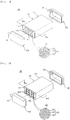
- FIGs. 1 and 2 are partially exploded perspective views of hollow fiber membrane modules in accordance with a first embodiment of the present invention.
- FIG. 1 illustrates a hollow fiber membrane module including one hollow fiber membrane 120 placed therein
- FIG. 2 illustrates a hollow fiber membrane module including a plurality of hollow fiber membranes 120 placed therein.
- a hollow fiber membrane module 100 in accordance with one embodiment of the present invention includes a housing 110, at least one hollow fiber membrane bundle 120, a partitioning part 130, potting parts 140 and 140', and covers 150 and 150'.
- the housing 110 and the covers 150 and 150' may form the external appearance of the hollow fiber membrane module 100 and be formed of hard plastic, such as polycarbonate, or metal.
- the cross-sections of the housing body 110 and the covers 150 and 150' in the width direction may have an angular shape, as exemplarily shown in FIGs. 1 and 2 , or have a circular shape, as exemplarily shown in FIG. 10 .
- the angular shape may be a polygonal shape, such as a rectangle, a square, a trapezoid, a parallelogram, a pentagon or a hexagon, and be a polygonal shape having rounded corners.
- the circular shape may be an oval.
- the covers 150 and 150' are assembled with both ends of the housing 110.
- the inlet 111 and the outlet 112 formed on the housing 110 may be arranged at one side of the housing 110 in parallel to each other, or be arranged on the housing 110 in a diagonal direction.
- FIG. 3 is a cross-sectional (longitudinal cross-sectional) view taken along line A-A of FIG. 1
- FIG. 4 is a cross-sectional (longitudinal cross-sectional) view taken along line A'-A' of FIG. 2 .
- One hollow fiber membrane bundle 120 or a plurality hollow fiber membrane bundles 120 is inserted into the housing 110 in the length direction according to capacities of the hollow fiber membrane module 100 and is supported by the partitioning part 130, thus being installed within the housing 110.
- Hollow fiber membranes 121 of the hollow fiber membrane bundle 120 selectively transmit moisture.
- the hollow fiber membranes 121 may be formed of known materials and a detailed description thereof will thus be omitted.
- the hollow fiber membrane bundle 120 may include 30 to 60% by volume of the hollow fiber membranes 121 with respect to the whole volume of the hollow fiber membrane bundle 120. Further, the hollow fiber membrane bundle may be surrounded by a mesh net.
- the partitioning part 130 may be provided within the housing 110 and support and partition at least one hollow fiber membrane bundle 120.
- the hollow fiber membrane bundles 120 are inserted into respective insertion spaces of the partitioning part 130, thus being supported by the partitioning part 130.
- the partitioning part 130 partitions the inside of the housing 110 into an inflow space S1, in which the humidifying fluid flowing into the housing 110 through the inlet 111 momentarily resides, and an outflow space S2, in which the humidifying fluid momentarily resides before being discharged to the outside through the outlet 112.
- the size of the inflow space S1 is equal to or greater than the size of the outflow space S2.
- the hot and humid humidifying fluid may reside in the inflow space S1 for a long time and then, the hot and humid humidifying fluid after purging may meet a cool and dry fluid to be humidified and exchange heat with the cool and dry fluid to be humidified, thereby enhancing heat transfer efficiency and maximizing humidifying efficiency of a product. Further, lowering of the temperature of the hot and humid humidifying fluid due to heat/material loss caused by the cool and dry fluid to be humidified may be prevented and, thus, the high temperature of the hot and humid humidifying fluid may be maintained.
- a ratio of a length L1 of the inflow space S1 in the length direction of the housing to a length L2 of the outflow space S2 in the length direction of the housing may be 6:4 ⁇ 9:1.
- a size of the inflow space S1 is greater than a size of the outflow space S2 such that the inflow space S1 and the outflow space S2 are asymmetrical, a time for which the hot and humid humidifying fluid humidifies the fluid to be humidified may be extended and thus humidifying efficiency may be enhanced.
- the partitioning part 130 may be formed integrally with the housing 110, or be formed separately from the housing 110 and then assembled with the housing 110.
- the partitioning part 130 may have different wall thicknesses according to materials thereof and, as the wall thickness of the partitioning part 130 is decreased, efficiency of the partitioning part 130 is increased.
- the wall thickness of the partitioning part 130 may generally be 0.1 mm ⁇ 70 mm and, particularly, the wall thickness of the partitioning part 130 formed of plastic may be 0.2 mm ⁇ 40 mm and the wall thickness of the partitioning part 130 formed of metal may be 0.2 mm ⁇ 50 mm.
- the partitioning part 130 is excessively thin and thus has difficulty in withstanding pressure and, if the wall thickness of the partitioning part 130 exceeds the upper limit of the above range, the inflow space in which the hot and humid humidifying fluid resides is not sufficiently secured and desired enhancement of humidifying effects is difficult.
- the potting parts 140 and 140' fill pores between the hollow fiber membranes 121 while binding the hollow fiber membranes 121 of the at least one hollow fiber membrane bundle 120 at ends (sides of fluid passage parts) of the at least one hollow fiber membrane bundle 120, and contact the inner surfaces of both ends of the housing 110 and thus hermetically seal the housing 110.
- the potting parts 140 and 140' may be formed of known materials and a detailed description thereof will thus be omitted.
- the potting parts 140 and 140' are formed within both ends of the housing 110 and, thus, both ends of the at least one hollow fiber membrane bundle 120 are fixed to the housing 110. Therefore, both ends of the housing 110 are closed by the potting parts 140 and 140' and thus flow paths along which the humidifying fluid passes are formed in the housing 110.
- a plurality of hollow fiber membrane bundles 120 is potted to the housing 110 at once.
- the housing covers 150 and 150' are combined with both ends of the housing 110.
- Fluid ports 151 and 151', through which the fluid to be humidified flows into and out of the housing 110, are formed at designated sides of the covers 150 and 150'.
- a pair of fluid ports 151 and 151' may be disposed in the same direction and, as exemplarily shown in FIGs. 1 and 2 , the fluid ports 151 and 151' may be disposed in the same direction as the inlet 111 and the outlet 112 formed on the housing 110. If the elements through which the fluids flow into and out of the housing 110 are disposed in the same direction, when the hollow fiber membrane module 100 is installed in a fuel cell system, the fuel cell system may be easily miniaturized due to spatial merits.
- the fluid to be humidified flowing into the fluid port 151 of one cover 150 is humidified while passing through inner ducts of the hollow fiber membranes 121 of the at least one hollow fiber membrane bundle 120 and is discharged to the outside through the fluid port 151' of the other cover 150'.
- FIGs. 5 and 6 are cross-sectional (longitudinal cross-sectional) views illustrating a hollow fiber membrane module in accordance with a second embodiment of the present invention and, in more detail, FIG. 5 illustrates a hollow fiber membrane module 200 in which hollow fiber membrane cartridges 160 and 160' are inserted into a housing 110, and FIG. 6 illustrates the housing 110 of the hollow fiber membrane module 200 before the hollow fiber membrane cartridges 160 and 160' are inserted into the housing 110.
- the hollow fiber membrane module 200 in accordance with the second embodiment includes the housing 110, hollow fiber membrane bundles 120, a partitioning part 130, potting parts 240 and 240', covers 150 and 150' and the hollow fiber membrane cartridges 160 and 160'.
- the hollow fiber membrane cartridges 160 and 160' which are potted together with the hollow fiber membrane bundles 120 to the housing 110 at once, are placed on both sides of the hollow fiber membrane bundles 120.
- the potting parts 240 and 240' fill pores between hollow fiber membranes 121 while binding the hollow fiber membranes 121 of the hollow fiber membrane bundles 120 at ends (sides of fluid passage parts) of the hollow fiber membrane bundles 120, and contact the inner surfaces of both ends of the housing 110 and thus hermetically seal the housing 110.
- the potting parts 240 and 240' may be formed of known materials and a detailed description thereof will thus be omitted.
- the potting parts 240 and 240' are formed within both ends of the housing 110 and, thus, both ends of the hollow fiber membrane bundles 120 within the hollow fiber membrane cartridges 160 and 160' are fixed to the housing 110. Therefore, both ends of the housing 110 are closed by the potting parts 240 and 240' and thus flow paths along which the humidifying fluid passes are formed in the housing 110.
- a plurality of hollow fiber membrane cartridges 160 and 160' and a plurality of hollow fiber membrane bundles 120 are potted to the housing 110 at once.
- the hollow fiber membrane cartridges 160 and 160' are placed on the outer surfaces of both sides of the hollow fiber membrane bundles 120 inserted into the housing 110 in the length direction of the housing, and one side of each of the hollow fiber membrane cartridges 160 and 160' is supported by the partitioning part 130.
- the hollow fiber membrane cartridge 160 or 160' is configured such that a plurality of fluid passage parts 162 or 162' is formed on the outer surface of one end of a body 161 or 161' having both sides which are open, and the fluid easily flows into spaces between the hollow fiber membranes 121 of the hollow fiber membrane bundle 120 through the fluid passage parts 162 or 162'. Further, a part of each of the hollow fiber membrane cartridges 160 and 160' is located at the side of the potting part 240 or 240' and thus potting of the hollow fiber membrane cartridges 160 and 160' is easily carried out.
- Windows 164 through which the fluid may flow into the cartridges, may be formed on the side walls of the bodies 161 and 161' of the hollow fiber membrane cartridges 160 and 160' formed in the length direction of the housing.
- the windows 164 allow the hot and humid humidifying fluid within the inflow space S1 or the outflow space S2 to be more effectively transferred to the hollow fiber membranes and may thus more effectively prevent lowering of the temperature of the hollow fiber membranes and drying of the hollow fiber membranes so as to enhance humidification performance.
- the size of the windows 164 may be equal to or smaller than the size of the fluid passage parts 162 and 162'. If the size of the windows 164 is greater than the size of the fluid passage parts 162 and 162', the fluid flowing from the inlet flows into the windows 164 earlier than the flow passage parts 162 and 162' and may thus interrupt an overall fluid flow.
- the hollow fiber membranes may be damaged and, thus, the windows 164 may be located at positions which do not directly face the inlet 111.
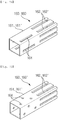
- FIG. 7A to 7D is a perspective view illustrating modifications of the hollow fiber membrane cartridge of the hollow fiber membrane module in accordance with the second embodiment of the present invention.
- windows 164 may extend in the length direction of the hollow fiber membrane cartridge 160, as exemplarily shown in FIG. 7A , a plurality of windows 164 having a circular shape may be alternately arranged, as exemplarily shown in FIG. 7B , or windows 164 may be formed as holes extending in a direction intersecting the length direction of the hollow fiber membrane cartridge 160 such that the sizes of the windows 164 may be gradually decreased (in FIG. 7C ) or gradually increased (in FIG. 7D ) as the windows 164 become far away from the end of the hollow fiber membrane cartridge 160.
- the cross-sections of the hollow fiber membrane cartridges 160 and 160' may have a rectangular shape, as exemplarily shown in FIGs. 7A and 7B , have a circular shape, as exemplarily shown in FIGs. 7C and 7D , or have an oval shape or various polygonal shapes and the polygonal shapes may have rounded corners.
- a ratio of an equivalent diameter to a length of the hollow fiber membrane bundle in the hollow fiber membrane cartridge may be 1:2 ⁇ 1:20.
- the equivalent diameter is a diameter to convert a surface area of a polygonal duct, which a fluid contacts, into a surface area of a circular duct having the same size, i.e., a diameter of a circular duct serving as a base when friction of flow, a velocity of flow, heat transfer, etc. are calculated.
- the equivalent diameter may be calculated through known methods according to polygonal or various shapes of ducts.
- the hollow fiber membrane cartridges 160 and 160' may be formed of any one of a liquid crystal polymer, a plastic including glass fibers and a metal. If the plastic includes glass fibers, the plastic may include 5 ⁇ 50% of glass fibers. When the plastic includes less than 5% of glass fibers, effects of the glass fibers are insignificant and, when the plastic includes more than 50% of glass fibers, strength of the hollow fiber membrane cartridges may be lowered.
- the metal may have thermal conductivity of 10 kcal/mh°C or more.
- the hollow fiber membrane cartridges 160 and 160' may have different wall thicknesses according to materials thereof, efficiency of the hollow fiber membrane cartridges 160 and 160' is increased as the wall thickness of the hollow fiber membrane cartridges 160 and 160' is decreased, and the wall thickness of the hollow fiber membrane cartridges 160 and 160' may be 10 mm or less. If the wall thickness of the hollow fiber membrane cartridges 160 and 160' exceeds 10 mm, heat transfer efficiency may be remarkably lowered.
- the wall thickness of the hollow fiber membrane cartridges 160 and 160' formed of a plastic may be 0.2 mm ⁇ 3 mm
- the wall thickness of the hollow fiber membrane cartridges 160 and 160' formed of a metal may be 0.1 mm ⁇ 5 mm.
- the remaining elements, i.e., the housing 110, the hollow fiber membrane bundles 120, the partitioning part 130 and the covers 150 and 150', of the hollow fiber membrane module 200 in accordance with the second embodiment are the same as those of the hollow fiber membrane module in accordance with the first embodiment and a detailed description thereof will thus be omitted.
- the humidifying fluid flows into the housing 110 along a path P1 through the inlet 111, resides in the inner space S1, flows into the hollow fiber membrane cartridges 160 at one end of the housing 110 through the fluid passage parts 162 or the windows 164, and moves to the hollow fiber membrane cartridges 160' at the other end of the housing 110 along a path P2.
- the humidifying fluid moves along the hollow fiber membrane cartridges 160 and 160', the humidifying fluid exchanges heat with the cool and dry fluid to be humidified flowing along the insides of the hollow fiber membranes 121 and then flows to the outflow space S2 through the fluid passage parts 162' or the windows 164' of the hollow fiber membrane cartridges 160' at the other end of the housing 110.
- the humidifying fluid which is dried through heat exchange, is discharged to the outside of the housing 110 along a path P3 through the outlet 112.
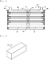
- FIG. 8 is a cross-sectional (longitudinal cross-sectional) view illustrating a hollow fiber membrane module in accordance with a third embodiment of the present invention
- FIG. 9 is a perspective view illustrating a vacant cartridge of FIG. 8
- a hollow fiber membrane module 300 in accordance with the third embodiment includes a housing 110, hollow fiber membrane bundles 120, a partitioning part 130, potting parts 340 and 340', covers 150 and 150', hollow fiber membrane cartridges 160 and 160', and vacant cartridges 170 and 170'.
- the vacant cartridges 170 and 170' which are inserted into the partitioning part 130 without hollow fiber membrane bundles and potted to the housing at once, are additionally provided within the housing 110 according to a humidifying capacity or a humidification degree.
- the cross-sections of the vacant cartridges 170 and 170' have a circular, oval or polygonal shape and the vacant cartridges 170 and 170' are closed so that no fluid flows into an insertion space of the partitioning part 130.
- the vacant cartridges 170 and 170' in accordance with the third embodiment may have a square column shape fitted into the insertion space of the partitioning part 130.
- the insertion space of the partitioning part 130, into which the vacant cartridge 170 is inserted, is vacant.
- the remaining elements of the hollow fiber membrane module in accordance with the third embodiment are the same as those of the hollow fiber membrane module in accordance with the second embodiment and a detailed description thereof will thus be omitted.
- FIG. 10 is a partially exploded perspective view of a hollow fiber membrane module in accordance with a fourth embodiment of the present invention.
- a hollow fiber membrane module 400 in accordance with the fourth embodiment includes a housing 410, hollow fiber membrane bundles 420, a partitioning part (not shown), potting parts 440, covers 450 and 450' and hollow fiber membrane cartridges (not shown).
- the hollow fiber membrane module 400 in accordance with the fourth embodiment has a cylindrical shape, and the remaining elements of the hollow fiber membrane module 400 are similar to those of the hollow fiber membrane modules in accordance with the first to third embodiments and a detailed description thereof will thus be omitted.
- the housing since the hollow fiber membrane cartridges are inserted into the housing and integrated with the housing, the housing may be manufactured according to the shape and number of the hollow fiber membrane cartridges and thus the hollow fiber membrane module may extend to products having various capacities, and utilization efficiency of the hollow fiber membrane cartridges may be increased according to the shape, number and size ratio of the hollow fiber membrane cartridges. Further, a plurality of hollow fiber membrane cartridges may be potted at once and thus manufacturing time and costs of the hollow fiber membrane module may be reduced through simple potting.
- test examples in which hollow fiber membrane modules in accordance with the second embodiment of the present invention are manufactured, comparative examples and a test.
- the test examples are only to exemplarily describe the invention and do not limit the spirit or scope of the invention.
- 4,200 polysulfone hollow fiber membranes (having an outer diameter of 900 ⁇ m and an inner diameter of 800 ⁇ m) were disposed in an angular housing (having a width of 250 mm, a height 150 mm and a length of 300 mm), both ends of the housing were covered with caps for formation of potting parts, and a potting composition was injected into spaces in a hollow fiber membrane bundle and a space between the hollow fiber membrane bundle and the housing and was then hardened so as to be sealed.
- the hollow fiber membrane module is a symmetrical hollow fiber membrane module in which a ratio of a length (150 mm) of an inflow space to a length (150 mm) of an outflow space is 5:5.
- the humidification module is a symmetrical humidification module in which a ratio of a length (150 mm) of an inflow space to a length (150 mm) of an outflow space is 5:5.
- 4,200 polysulfone hollow fiber membranes (having an outer diameter of 900 ⁇ m and an inner diameter of 800 ⁇ m) were divided into 12 bundles (each bundle having 350 hollow fiber membranes), and hollow fiber membrane cartridges were placed on both ends of the respective bundles and then inserted into insertion spaces of a partitioning part formed in an angular housing (having a width of 250 mm, a height 150 mm and a length of 300 mm).
- the hollow fiber membrane module is an asymmetrical hollow fiber membrane module in which a ratio of a length (180 mm) of an inflow space to a length (120 mm) of an outflow space is 6:4.
- 4,200 polysulfone hollow fiber membranes (having an outer diameter of 900 ⁇ m and an inner diameter of 800 ⁇ m) were divided into 12 bundles having a rectangular cross-section (each bundle having 350 hollow fiber membranes), and hollow fiber membrane cartridges were placed on both ends of the respective bundles and then inserted into insertion spaces of a partitioning part formed in an angular housing (having a width of 250 mm, a height 150 mm and a length of 300 mm).
- the hollow fiber membrane module is an asymmetrical hollow fiber membrane module in which a ratio of a length (240 mm) of an inflow space to a length (60 mm) of an outflow space is 8:2.
- 4,200 polysulfone hollow fiber membranes (having an outer diameter of 900 ⁇ m and an inner diameter of 800 ⁇ m) were integrated as one cartridge, the cartridge was disposed in an angular housing (having a width of 250 mm, a height 150 mm and a length of 300 mm), potting parts were formed at both ends of the housing by performing potting of the cartridge one time, and both ends of the housing were covered with covers, thus manufacturing a humidification module.
- Dry air was supplied to the insides and outsides of the hollow fiber membranes of the hollow fiber membrane modules manufactured by Test Examples and Comparative Example at a rate of 50 g/sec, the outsides of the hollow fiber membranes were fixed under conditions of a temperature of 70 °C and a humidity of 90%, the insides of the hollow fiber membranes were fixed under conditions of a temperature of 40 °C and a humidity of 10%, and thus gas-gas humidification was carried out.
- Humidification performance was acquired by measuring temperature and humidity at a point, from which air flowing inside the hollow fiber membranes is humidified and then discharged, and converting the same into a dew point, and Table 1 below shows acquired results together with number of times of potting.
- Test example 1 Division Test example 1
- Test example 2 Test example 3
- Test example 4 Comparative example 1 Position of partitioning part 5:5 5:5 6:4 8:2 - Humidification performance (°C) 57.5 58.3 59.3 60.3 56.5
Landscapes
- Chemical & Material Sciences (AREA)
- Chemical Kinetics & Catalysis (AREA)
- Life Sciences & Earth Sciences (AREA)
- Engineering & Computer Science (AREA)
- Manufacturing & Machinery (AREA)
- Sustainable Development (AREA)
- Sustainable Energy (AREA)
- Electrochemistry (AREA)
- General Chemical & Material Sciences (AREA)
- Separation Using Semi-Permeable Membranes (AREA)
- Fuel Cell (AREA)
Abstract
Description
- The present invention relates to a hollow fiber membrane module, and more particularly, to a hollow fiber membrane module in which a retention time of a hot and humid humidifying fluid is increased and thus heat or material transfer efficiency may be increased to maximize humidifying efficiency of a product.
- In general, a fuel cell refers to a power generation-type cell which produces electricity by bonding hydrogen and oxygen. The fuel cell may continuously produce electricity as long as hydrogen and oxygen are supplied, differently from general chemical cells, such as batteries or storage batteries, and have no heat loss, thus having efficiency twice that of an internal combustion engine. Further, the fuel cell converts chemical energy, generated by bonding hydrogen and oxygen, directly into electrical energy and thus discharges few pollutants. Therefore, the fuel cell is advantageous in that it is eco-friendly and reduces worries about resource depletion owing to increase in energy consumption. Fuel cells may be generally classified into a polymer electrolyte membrane fuel cell (PEMFC), a phosphoric acid fuel cell (PAFC), a molten carbonate fuel cell (MCFC), a solid oxide fuel cell (SOFC), an alkaline fuel cell (AFC), etc. according to kinds of electrolytes used. The respective fuel cells are basically operated by the same principle, but kinds of fuels used, operating temperatures, catalysts, electrolytes, etc. of the respective fuel cells are different. Thereamong, it is known that PEMFCs are operated at a low temperature, as compared to other fuel cells, have high power density, are small in size, and may thus be promising as not only small mounting-type power generation equipment but also transportation systems.
- One of important factors to improve performance of the PEMFCs is to supply a designated amount or more of moisture to a polymer electrolyte membrane or a proton exchange membrane (PEM) of a membrane-electrolyte assembly (MEA) so as to maintain a desired water content. The reason for this is that, when the PEM is dried, power generation efficiency is rapidly decreased. In order to humidify the PEM, 1) a bubbler humidification method in which moisture is supplied by filling a pressure vessel with water and then causing target gas to pass through a diffuser, 2) a direct injection method in which an amount of supply moisture necessary for fuel cell reaction is calculated and then moisture is supplied directly to a gas flow pipe through a solenoid valve, and 3) a humidification membrane method in which moisture is supplied to a gas fluidized bed using a polymeric separation membrane. Thereamong, the humidification membrane method, in which vapor is fed to gas supplied to a polymer electrolyte membrane using a membrane selectively transmitting only vapor included in exhaust gas so as to humidify the polymer electrolyte membrane, is advantageous in that a humidifier may be lightweight and small.
- As selectively transmitting membranes used in the humidification membrane method, hollow fiber membranes having a large transmission area per unit volume, if a module is formed, may be used. That is, if a humidifier is manufactured using hollow fiber membranes, high integration of the hollow fiber membranes having a large contact surface area is achieved and a fuel cell may be sufficiently humidified even at a small capacity of the humidifier, a low-cost material may be used, and moisture and heat included in unreacted gas of a high temperature discharged from the fuel cell may be collected and then reused through the humidifier.
- However, a conventional hollow fiber membrane module has a short time for which a hot and humid humidifying fluid may directly contact hollow fiber membranes in the module and thereby have limits in raising heat/material transfer efficiency with a cool and dry fluid to be humidified and limits in enhancing humidifying efficiency of a product.
- Further, in order to increase the capacity of hollow fiber membrane modules, technology in which a hollow fiber membrane bundle is partitioned or unit modules are integrated as cartridges is used. However, if such technology is used, a time taken to manufacture individual modules of the cartridges is long and thus manufacturing costs may be increased and, when the bundle is partitioned, workability in partitioning is lowered and thus quality variation may be increased.
-
- Korean Patent Laid-Open Publication No.
10-2011-0109814 (Publication Date: October 6, 2011 - Korean Patent Laid-Open Publication No.
10-2013-0034404 (Publication Date: April 5, 2013 - Therefore, the present invention has been made in view of the above problems, and it is an object of the present invention to provide a hollow fiber membrane module in which heat/material transfer efficiency may be raised due to increase in a contact time between a hot and humid humidifying fluid and a cool and dry fluid to be humidified and, thus, humidifying efficiency of a product may be maximized.
- It is another object of the present invention to provide a hollow fiber membrane module in which hollow fiber membrane cartridges may be inserted into a housing and thus integrated with the housing so as to extend to products having various capacities, to increase utilization efficiency of the hollow fiber membrane cartridges and to reduce manufacturing time and costs through simple potting.
- The object of the present invention can be achieved by providing a hollow fiber membrane module including a housing provided with an inlet formed at one end thereof and an outlet formed at the other end thereof, a hot and humid humidifying fluid flowing into the housing through the inlet and the humidifying fluid after humidifying the interior of the housing flowing out of the housing through the outlet, at least one hollow fiber membrane bundle inserted into the housing in a length direction of the housing, a partitioning part configured to support the at least one hollow fiber membrane bundle and to partition the interior of the housing into an inflow space, in which the humidifying fluid flowing into the housing momentarily resides, and an outflow space, in which the humidifying fluid momentarily resides before being discharged to the outside of the housing through the outlet, and potting parts configured to pot both ends of the at least one hollow fiber membrane bundle to the housing.
- A size of the inflow space may be equal to or greater than a size of the outflow space.
- Hollow fiber membrane cartridges, potted together with the at least one hollow fiber membrane bundle to the housing at once, may be placed on both ends of the at least one follow fiber membrane bundle.
- Vacant cartridges, inserted into the partitioning part without hollow fiber membrane bundles and potted to the housing at once, may be additionally provided within the housing according to a humidifying capacity or a humidification degree.
- The vacant cartridges may have a circular, oval or polygonal cross-section and be closed so that no fluid flows into an insertion space of the partitioning part.
- Fluid passage parts may be formed on the hollow fiber membrane cartridges so as to allow the fluid to easily flow into the at least one hollow fiber membrane bundle.
- The at least one hollow fiber membrane bundle in the hollow fiber membrane cartridges may include 30 to 60% by volume of hollow fiber membranes with respect to a whole volume thereof.
- The housing may have a circular, oval or polygonal cross-section.
- The hollow fiber membrane cartridges may have a circular, oval or polygonal cross-section. A ratio of an equivalent diameter to a length of the at least one hollow fiber membrane bundle in the hollow fiber membrane cartridges may be 1:2 ∼ 1:20.
- A hollow fiber membrane module in accordance with the present invention may increase a retention time of a hot and humid humidifying fluid in an inflow space into which the hot and humid humidifying fluid flows and thus enhance heat/material transfer efficiency to maximize humidifying efficiency of product, and prevent drop in temperature of the hot and humid humidifying fluid due to heat/material loss caused by the cool and dry fluid to be humidified, as the hot and humid humidifying fluid resides in the inflow space.
- Further, since hollow fiber membrane cartridges are inserted into a housing and integrated with the housing, the housing may be manufactured according to the shape and number of the hollow fiber membrane cartridges and thus the hollow fiber membrane module may extend to products having various capacities, and utilization efficiency of the hollow fiber membrane cartridges may be increased according to the shape, number and size ratio of the hollow fiber membrane cartridges. Further, the hollow fiber membrane cartridges and hollow fiber membranes may be potted at once and thus manufacturing time and costs of the hollow fiber membrane module may be reduced through simple potting.
-
-
FIGs. 1 and 2 are partially exploded perspective views of hollow fiber membrane modules in accordance with a first embodiment of the present invention. -
FIG. 3 is a cross-sectional (longitudinal cross-sectional) view taken along line A-A ofFIG. 1 . -
FIG. 4 is a cross-sectional (longitudinal cross-sectional) view taken along line A'-A' ofFIG. 2 . -
FIGs. 5 and 6 are cross-sectional (longitudinal cross-sectional) views illustrating a hollow fiber membrane module in accordance with a second embodiment of the present invention. -
FIG. 7A to 7D is a perspective view illustrating modifications of a hollow fiber membrane cartridge of the hollow fiber membrane module in accordance with the second embodiment of the present invention. -
FIG. 8 is a cross-sectional (longitudinal cross-sectional) view illustrating a hollow fiber membrane module in accordance with a third embodiment of the present invention. -
FIG. 9 is a perspective view illustrating a vacant cartridge ofFIG. 8 . -
FIG. 10 is a partially exploded perspective view of a hollow fiber membrane module in accordance with a fourth embodiment of the present invention. -
FIG. 11 is a longitudinal cross-sectional view of a conventional hollow fiber membrane module. -
FIG. 12 is a transversal cross-sectional view of the conventional hollow fiber membrane module. - Reference will now be made in detail to the preferred embodiments of the present invention, examples of which are illustrated in the accompanying drawings. However, those skilled in the art will appreciate that various modifications, additions and substitutions are possible, and the present invention is not limited to these embodiments.
-
FIGs. 1 and 2 are partially exploded perspective views of hollow fiber membrane modules in accordance with a first embodiment of the present invention.FIG. 1 illustrates a hollow fiber membrane module including onehollow fiber membrane 120 placed therein, andFIG. 2 illustrates a hollow fiber membrane module including a plurality ofhollow fiber membranes 120 placed therein. - As exemplarily shown in these figures, a hollow
fiber membrane module 100 in accordance with one embodiment of the present invention includes ahousing 110, at least one hollowfiber membrane bundle 120, a partitioningpart 130,potting parts 140 and 140', and covers 150 and 150'. - The
housing 110 and thecovers 150 and 150' may form the external appearance of the hollowfiber membrane module 100 and be formed of hard plastic, such as polycarbonate, or metal. Further, the cross-sections of thehousing body 110 and thecovers 150 and 150' in the width direction may have an angular shape, as exemplarily shown inFIGs. 1 and 2 , or have a circular shape, as exemplarily shown inFIG. 10 . The angular shape may be a polygonal shape, such as a rectangle, a square, a trapezoid, a parallelogram, a pentagon or a hexagon, and be a polygonal shape having rounded corners. Further, the circular shape may be an oval. - An
inlet 111, into which a hot and humid humidifying fluid flows, is formed at one end of thehousing 110, and anoutlet 112, from which the humidifying fluid after humidifying the inside of thehousing 110 is discharged, is formed at the other end of thehousing 110. Thecovers 150 and 150' are assembled with both ends of thehousing 110. - The
inlet 111 and theoutlet 112 formed on thehousing 110 may be arranged at one side of thehousing 110 in parallel to each other, or be arranged on thehousing 110 in a diagonal direction. -
FIG. 3 is a cross-sectional (longitudinal cross-sectional) view taken along line A-A ofFIG. 1 , andFIG. 4 is a cross-sectional (longitudinal cross-sectional) view taken along line A'-A' ofFIG. 2 . - One hollow
fiber membrane bundle 120 or a plurality hollow fiber membrane bundles 120 is inserted into thehousing 110 in the length direction according to capacities of the hollowfiber membrane module 100 and is supported by thepartitioning part 130, thus being installed within thehousing 110. -
Hollow fiber membranes 121 of the hollowfiber membrane bundle 120 selectively transmit moisture. Thehollow fiber membranes 121 may be formed of known materials and a detailed description thereof will thus be omitted. The hollowfiber membrane bundle 120 may include 30 to 60% by volume of thehollow fiber membranes 121 with respect to the whole volume of the hollowfiber membrane bundle 120. Further, the hollow fiber membrane bundle may be surrounded by a mesh net. - The
partitioning part 130 may be provided within thehousing 110 and support and partition at least one hollowfiber membrane bundle 120. The hollow fiber membrane bundles 120 are inserted into respective insertion spaces of thepartitioning part 130, thus being supported by thepartitioning part 130. Further, thepartitioning part 130 partitions the inside of thehousing 110 into an inflow space S1, in which the humidifying fluid flowing into thehousing 110 through theinlet 111 momentarily resides, and an outflow space S2, in which the humidifying fluid momentarily resides before being discharged to the outside through theoutlet 112. The size of the inflow space S1 is equal to or greater than the size of the outflow space S2. - Since the hollow
fiber membrane module 100 secures the wider inflow space due to formation of the partitioning part, as compared to a conventional hollow fiber membrane module, the hot and humid humidifying fluid may reside in the inflow space S1 for a long time and then, the hot and humid humidifying fluid after purging may meet a cool and dry fluid to be humidified and exchange heat with the cool and dry fluid to be humidified, thereby enhancing heat transfer efficiency and maximizing humidifying efficiency of a product. Further, lowering of the temperature of the hot and humid humidifying fluid due to heat/material loss caused by the cool and dry fluid to be humidified may be prevented and, thus, the high temperature of the hot and humid humidifying fluid may be maintained. - Particularly, a ratio of a length L1 of the inflow space S1 in the length direction of the housing to a length L2 of the outflow space S2 in the length direction of the housing may be 6:4 ∼ 9:1.
- If a size of the inflow space S1 is greater than a size of the outflow space S2 such that the inflow space S1 and the outflow space S2 are asymmetrical, a time for which the hot and humid humidifying fluid humidifies the fluid to be humidified may be extended and thus humidifying efficiency may be enhanced.
- The
partitioning part 130 may be formed integrally with thehousing 110, or be formed separately from thehousing 110 and then assembled with thehousing 110. Thepartitioning part 130 may have different wall thicknesses according to materials thereof and, as the wall thickness of thepartitioning part 130 is decreased, efficiency of thepartitioning part 130 is increased. The wall thickness of thepartitioning part 130 may generally be 0.1 mm ∼ 70 mm and, particularly, the wall thickness of thepartitioning part 130 formed of plastic may be 0.2 mm ∼ 40 mm and the wall thickness of thepartitioning part 130 formed of metal may be 0.2 mm ∼ 50 mm. - If the wall thickness of the
partitioning part 130 is less than the lower limit of the above range, thepartitioning part 130 is excessively thin and thus has difficulty in withstanding pressure and, if the wall thickness of thepartitioning part 130 exceeds the upper limit of the above range, the inflow space in which the hot and humid humidifying fluid resides is not sufficiently secured and desired enhancement of humidifying effects is difficult. - The
potting parts 140 and 140' fill pores between thehollow fiber membranes 121 while binding thehollow fiber membranes 121 of the at least one hollowfiber membrane bundle 120 at ends (sides of fluid passage parts) of the at least one hollowfiber membrane bundle 120, and contact the inner surfaces of both ends of thehousing 110 and thus hermetically seal thehousing 110. Thepotting parts 140 and 140' may be formed of known materials and a detailed description thereof will thus be omitted. - The
potting parts 140 and 140' are formed within both ends of thehousing 110 and, thus, both ends of the at least one hollowfiber membrane bundle 120 are fixed to thehousing 110. Therefore, both ends of thehousing 110 are closed by thepotting parts 140 and 140' and thus flow paths along which the humidifying fluid passes are formed in thehousing 110. In the present invention, a plurality of hollow fiber membrane bundles 120 is potted to thehousing 110 at once. - The housing covers 150 and 150' are combined with both ends of the
housing 110.Fluid ports 151 and 151', through which the fluid to be humidified flows into and out of thehousing 110, are formed at designated sides of thecovers 150 and 150'. A pair offluid ports 151 and 151' may be disposed in the same direction and, as exemplarily shown inFIGs. 1 and 2 , thefluid ports 151 and 151' may be disposed in the same direction as theinlet 111 and theoutlet 112 formed on thehousing 110. If the elements through which the fluids flow into and out of thehousing 110 are disposed in the same direction, when the hollowfiber membrane module 100 is installed in a fuel cell system, the fuel cell system may be easily miniaturized due to spatial merits. The fluid to be humidified flowing into thefluid port 151 of onecover 150 is humidified while passing through inner ducts of thehollow fiber membranes 121 of the at least one hollowfiber membrane bundle 120 and is discharged to the outside through the fluid port 151' of the other cover 150'. -
FIGs. 5 and 6 are cross-sectional (longitudinal cross-sectional) views illustrating a hollow fiber membrane module in accordance with a second embodiment of the present invention and, in more detail,FIG. 5 illustrates a hollowfiber membrane module 200 in which hollowfiber membrane cartridges 160 and 160' are inserted into ahousing 110, andFIG. 6 illustrates thehousing 110 of the hollowfiber membrane module 200 before the hollowfiber membrane cartridges 160 and 160' are inserted into thehousing 110. - As exemplarily shown in these figures, the hollow
fiber membrane module 200 in accordance with the second embodiment includes thehousing 110, hollow fiber membrane bundles 120, apartitioning part 130, pottingparts 240 and 240', covers 150 and 150' and the hollowfiber membrane cartridges 160 and 160'. In the second embodiment, the hollowfiber membrane cartridges 160 and 160', which are potted together with the hollow fiber membrane bundles 120 to thehousing 110 at once, are placed on both sides of the hollow fiber membrane bundles 120. - The
potting parts 240 and 240' fill pores betweenhollow fiber membranes 121 while binding thehollow fiber membranes 121 of the hollow fiber membrane bundles 120 at ends (sides of fluid passage parts) of the hollow fiber membrane bundles 120, and contact the inner surfaces of both ends of thehousing 110 and thus hermetically seal thehousing 110. Thepotting parts 240 and 240' may be formed of known materials and a detailed description thereof will thus be omitted. - The
potting parts 240 and 240' are formed within both ends of thehousing 110 and, thus, both ends of the hollow fiber membrane bundles 120 within the hollowfiber membrane cartridges 160 and 160' are fixed to thehousing 110. Therefore, both ends of thehousing 110 are closed by thepotting parts 240 and 240' and thus flow paths along which the humidifying fluid passes are formed in thehousing 110. In the present invention, a plurality of hollowfiber membrane cartridges 160 and 160' and a plurality of hollow fiber membrane bundles 120 are potted to thehousing 110 at once. - The hollow
fiber membrane cartridges 160 and 160' are placed on the outer surfaces of both sides of the hollow fiber membrane bundles 120 inserted into thehousing 110 in the length direction of the housing, and one side of each of the hollowfiber membrane cartridges 160 and 160' is supported by thepartitioning part 130. The hollowfiber membrane cartridge 160 or 160' is configured such that a plurality offluid passage parts 162 or 162' is formed on the outer surface of one end of a body 161 or 161' having both sides which are open, and the fluid easily flows into spaces between thehollow fiber membranes 121 of the hollowfiber membrane bundle 120 through thefluid passage parts 162 or 162'. Further, a part of each of the hollowfiber membrane cartridges 160 and 160' is located at the side of thepotting part 240 or 240' and thus potting of the hollowfiber membrane cartridges 160 and 160' is easily carried out. -
Windows 164, through which the fluid may flow into the cartridges, may be formed on the side walls of the bodies 161 and 161' of the hollowfiber membrane cartridges 160 and 160' formed in the length direction of the housing. - The
windows 164 allow the hot and humid humidifying fluid within the inflow space S1 or the outflow space S2 to be more effectively transferred to the hollow fiber membranes and may thus more effectively prevent lowering of the temperature of the hollow fiber membranes and drying of the hollow fiber membranes so as to enhance humidification performance. - Further, the size of the
windows 164 may be equal to or smaller than the size of thefluid passage parts 162 and 162'. If the size of thewindows 164 is greater than the size of thefluid passage parts 162 and 162', the fluid flowing from the inlet flows into thewindows 164 earlier than theflow passage parts 162 and 162' and may thus interrupt an overall fluid flow. - Further, when the hot and humid humidifying fluid flowing into the
inlet 111 directly contacts the hollow fiber membranes, the hollow fiber membranes may be damaged and, thus, thewindows 164 may be located at positions which do not directly face theinlet 111. -
FIG. 7A to 7D is a perspective view illustrating modifications of the hollow fiber membrane cartridge of the hollow fiber membrane module in accordance with the second embodiment of the present invention. - Further,
windows 164 may extend in the length direction of the hollowfiber membrane cartridge 160, as exemplarily shown inFIG. 7A , a plurality ofwindows 164 having a circular shape may be alternately arranged, as exemplarily shown inFIG. 7B , orwindows 164 may be formed as holes extending in a direction intersecting the length direction of the hollowfiber membrane cartridge 160 such that the sizes of thewindows 164 may be gradually decreased (inFIG. 7C ) or gradually increased (inFIG. 7D ) as thewindows 164 become far away from the end of the hollowfiber membrane cartridge 160. - The cross-sections of the hollow
fiber membrane cartridges 160 and 160' may have a rectangular shape, as exemplarily shown inFIGs. 7A and 7B , have a circular shape, as exemplarily shown inFIGs. 7C and 7D , or have an oval shape or various polygonal shapes and the polygonal shapes may have rounded corners. - A ratio of an equivalent diameter to a length of the hollow fiber membrane bundle in the hollow fiber membrane cartridge may be 1:2 ∼ 1:20. Here, the equivalent diameter is a diameter to convert a surface area of a polygonal duct, which a fluid contacts, into a surface area of a circular duct having the same size, i.e., a diameter of a circular duct serving as a base when friction of flow, a velocity of flow, heat transfer, etc. are calculated. The equivalent diameter may be calculated through known methods according to polygonal or various shapes of ducts.
- The hollow
fiber membrane cartridges 160 and 160' may be formed of any one of a liquid crystal polymer, a plastic including glass fibers and a metal. If the plastic includes glass fibers, the plastic may include 5 ∼ 50% of glass fibers. When the plastic includes less than 5% of glass fibers, effects of the glass fibers are insignificant and, when the plastic includes more than 50% of glass fibers, strength of the hollow fiber membrane cartridges may be lowered. The metal may have thermal conductivity of 10 kcal/mh°C or more. - The hollow
fiber membrane cartridges 160 and 160' may have different wall thicknesses according to materials thereof, efficiency of the hollowfiber membrane cartridges 160 and 160' is increased as the wall thickness of the hollowfiber membrane cartridges 160 and 160' is decreased, and the wall thickness of the hollowfiber membrane cartridges 160 and 160' may be 10 mm or less. If the wall thickness of the hollowfiber membrane cartridges 160 and 160' exceeds 10 mm, heat transfer efficiency may be remarkably lowered. In general, the wall thickness of the hollowfiber membrane cartridges 160 and 160' formed of a plastic may be 0.2 mm ∼ 3 mm, and the wall thickness of the hollowfiber membrane cartridges 160 and 160' formed of a metal may be 0.1 mm ∼ 5 mm. - The remaining elements, i.e., the
housing 110, the hollow fiber membrane bundles 120, thepartitioning part 130 and thecovers 150 and 150', of the hollowfiber membrane module 200 in accordance with the second embodiment are the same as those of the hollow fiber membrane module in accordance with the first embodiment and a detailed description thereof will thus be omitted. - The humidifying fluid flows into the
housing 110 along a path P1 through theinlet 111, resides in the inner space S1, flows into the hollowfiber membrane cartridges 160 at one end of thehousing 110 through thefluid passage parts 162 or thewindows 164, and moves to the hollow fiber membrane cartridges 160' at the other end of thehousing 110 along a path P2. As the humidifying fluid moves along the hollowfiber membrane cartridges 160 and 160', the humidifying fluid exchanges heat with the cool and dry fluid to be humidified flowing along the insides of thehollow fiber membranes 121 and then flows to the outflow space S2 through the fluid passage parts 162' or the windows 164' of the hollow fiber membrane cartridges 160' at the other end of thehousing 110. The humidifying fluid, which is dried through heat exchange, is discharged to the outside of thehousing 110 along a path P3 through theoutlet 112. -
FIG. 8 is a cross-sectional (longitudinal cross-sectional) view illustrating a hollow fiber membrane module in accordance with a third embodiment of the present invention, andFIG. 9 is a perspective view illustrating a vacant cartridge ofFIG. 8 . As exemplarily shown in these figures, a hollowfiber membrane module 300 in accordance with the third embodiment includes ahousing 110, hollow fiber membrane bundles 120, apartitioning part 130, pottingparts 340 and 340', covers 150 and 150', hollowfiber membrane cartridges 160 and 160', andvacant cartridges 170 and 170'. In the second embodiment, thevacant cartridges 170 and 170', which are inserted into thepartitioning part 130 without hollow fiber membrane bundles and potted to the housing at once, are additionally provided within thehousing 110 according to a humidifying capacity or a humidification degree. - The cross-sections of the
vacant cartridges 170 and 170' have a circular, oval or polygonal shape and thevacant cartridges 170 and 170' are closed so that no fluid flows into an insertion space of thepartitioning part 130. Thevacant cartridges 170 and 170' in accordance with the third embodiment may have a square column shape fitted into the insertion space of thepartitioning part 130. The insertion space of thepartitioning part 130, into which thevacant cartridge 170 is inserted, is vacant. The remaining elements of the hollow fiber membrane module in accordance with the third embodiment are the same as those of the hollow fiber membrane module in accordance with the second embodiment and a detailed description thereof will thus be omitted. -
FIG. 10 is a partially exploded perspective view of a hollow fiber membrane module in accordance with a fourth embodiment of the present invention. As exemplarily shown in this figure, a hollowfiber membrane module 400 in accordance with the fourth embodiment includes ahousing 410, hollow fiber membrane bundles 420, a partitioning part (not shown), pottingparts 440, covers 450 and 450' and hollow fiber membrane cartridges (not shown). The hollowfiber membrane module 400 in accordance with the fourth embodiment has a cylindrical shape, and the remaining elements of the hollowfiber membrane module 400 are similar to those of the hollow fiber membrane modules in accordance with the first to third embodiments and a detailed description thereof will thus be omitted. - In the above-described hollow fiber membrane module, since the hollow fiber membrane cartridges are inserted into the housing and integrated with the housing, the housing may be manufactured according to the shape and number of the hollow fiber membrane cartridges and thus the hollow fiber membrane module may extend to products having various capacities, and utilization efficiency of the hollow fiber membrane cartridges may be increased according to the shape, number and size ratio of the hollow fiber membrane cartridges. Further, a plurality of hollow fiber membrane cartridges may be potted at once and thus manufacturing time and costs of the hollow fiber membrane module may be reduced through simple potting.
- Hereinafter, the configuration and effects of the present invention will be described in more detail through test examples in which hollow fiber membrane modules in accordance with the second embodiment of the present invention are manufactured, comparative examples and a test. The test examples are only to exemplarily describe the invention and do not limit the spirit or scope of the invention.
- 4,200 polysulfone hollow fiber membranes (having an outer diameter of 900 µm and an inner diameter of 800 µm) were disposed in an angular housing (having a width of 250 mm, a
height 150 mm and a length of 300 mm), both ends of the housing were covered with caps for formation of potting parts, and a potting composition was injected into spaces in a hollow fiber membrane bundle and a space between the hollow fiber membrane bundle and the housing and was then hardened so as to be sealed. After the caps for formation of potting parts were removed, ends of the hardened potting composition were cut so as to form potting parts in which ends of the hollow fiber membrane bundle are exposed to the cut ends of the hardened potting composition, and both ends of the housing were covered with covers, thus manufacturing a hollow fiber membrane module. Here, the hollow fiber membrane module is a symmetrical hollow fiber membrane module in which a ratio of a length (150 mm) of an inflow space to a length (150 mm) of an outflow space is 5:5. - 4,200 polysulfone hollow fiber membranes (having an outer diameter of 900 µm and an inner diameter of 800 µm) were divided into 12 bundles (each bundle having 350 hollow fiber membranes) respectively integrated as cartridges, the 12 cartridges were disposed in an angular housing (having a width of 250 mm, a
height 150 mm and a length of 300 mm) and potted to the housing to form potting parts at both ends of the housing, and both ends of the housing were covered with covers, thus manufacturing a humidification module. Here, the humidification module is a symmetrical humidification module in which a ratio of a length (150 mm) of an inflow space to a length (150 mm) of an outflow space is 5:5. - 4,200 polysulfone hollow fiber membranes (having an outer diameter of 900 µm and an inner diameter of 800 µm) were divided into 12 bundles (each bundle having 350 hollow fiber membranes), and hollow fiber membrane cartridges were placed on both ends of the respective bundles and then inserted into insertion spaces of a partitioning part formed in an angular housing (having a width of 250 mm, a
height 150 mm and a length of 300 mm). - Both ends of the housing were covered with caps for formation of potting parts, and a potting composition was injected into spaces between the hollow fiber membrane bundles and a space between the cartridges and the housing and was then hardened so as to be sealed. After the caps for formation of potting parts were removed, ends of the hardened potting composition were cut so as to form potting parts in which ends of the hollow fiber membrane bundles are exposed to the cut ends of the hardened potting composition, and both ends of the housing were covered with covers, thus manufacturing a hollow fiber membrane module. Here, the hollow fiber membrane module is an asymmetrical hollow fiber membrane module in which a ratio of a length (180 mm) of an inflow space to a length (120 mm) of an outflow space is 6:4.
- 4,200 polysulfone hollow fiber membranes (having an outer diameter of 900 µm and an inner diameter of 800 µm) were divided into 12 bundles having a rectangular cross-section (each bundle having 350 hollow fiber membranes), and hollow fiber membrane cartridges were placed on both ends of the respective bundles and then inserted into insertion spaces of a partitioning part formed in an angular housing (having a width of 250 mm, a
height 150 mm and a length of 300 mm). - Both ends of the housing were covered with caps for formation of potting parts, and a potting composition was injected into spaces between the hollow fiber membrane bundles and a space between the cartridges and the housing and was then hardened so as to be sealed. After the caps for formation of potting parts were removed, ends of the hardened potting composition were cut so as to form potting parts in which ends of the hollow fiber membrane bundles are exposed to the cut ends of the hardened potting composition, and both ends of the housing were covered with covers, thus manufacturing a hollow fiber membrane module. Here, the hollow fiber membrane module is an asymmetrical hollow fiber membrane module in which a ratio of a length (240 mm) of an inflow space to a length (60 mm) of an outflow space is 8:2.
- As exemplarily shown in
FIGs. 11 and12 , 4,200 polysulfone hollow fiber membranes (having an outer diameter of 900 µm and an inner diameter of 800 µm) were integrated as one cartridge, the cartridge was disposed in an angular housing (having a width of 250 mm, aheight 150 mm and a length of 300 mm), potting parts were formed at both ends of the housing by performing potting of the cartridge one time, and both ends of the housing were covered with covers, thus manufacturing a humidification module. - Dry air was supplied to the insides and outsides of the hollow fiber membranes of the hollow fiber membrane modules manufactured by Test Examples and Comparative Example at a rate of 50 g/sec, the outsides of the hollow fiber membranes were fixed under conditions of a temperature of 70 °C and a humidity of 90%, the insides of the hollow fiber membranes were fixed under conditions of a temperature of 40 °C and a humidity of 10%, and thus gas-gas humidification was carried out.
- Humidification performance was acquired by measuring temperature and humidity at a point, from which air flowing inside the hollow fiber membranes is humidified and then discharged, and converting the same into a dew point, and Table 1 below shows acquired results together with number of times of potting.
-
[Table 1] Division Test example 1 Test example 2 Test example 3 Test example 4 Comparative example 1 Position of partitioning part 5:5 5:5 6:4 8:2 - Humidification performance (°C) 57.5 58.3 59.3 60.3 56.5 - With reference to Table 1, it may be understood that the hollow fiber membrane modules manufactured by Test Examples 1 to 4 have better humidification performance than the hollow fiber membrane module manufactured by Comparative Example 1.
- It will be apparent to those skilled in the art that various modifications and variations can be made in the present invention without departing from the spirit or scope of the invention. Thus, it is intended that the present invention cover the modifications and variations of this invention provided they fall within the scope of the appended claims and their equivalents.
-
- 100, 200: hollow fiber membrane module
- 110: housing 111: inlet
- 112: outlet 120: hollow fiber membrane bundle
- 121: hollow fiber membrane 130: partitioning part
- 140, 140': potting
part 150, 150': cover - 151, 151':
fluid port 160, 160': hollow fiber membrane cartridge - 161, 161':
body 162, 162': fluid passage part - 170: vacant cartridge
- S1: inflow space S2: outflow space
Claims (12)
- A hollow fiber membrane module comprising:a housing provided with an inlet formed at one end thereof and an outlet formed at the other end thereof, a hot and humid humidifying fluid flowing into the housing through the inlet and the humidifying fluid after humidifying a cool and dry fluid flowing out of the housing through the outlet;at least one hollow fiber membrane bundle inserted into the housing in a length direction of the housing;a partitioning part configured to support the at least one hollow fiber membrane bundle and to partition the interior of the housing into an inflow space, in which the humidifying fluid flowing into the housing momentarily resides, and an outflow space, in which the humidifying fluid momentarily resides before being discharged to the outside of the housing through the outlet; andpotting parts configured to pot both ends of the at least one hollow fiber membrane bundle to the housing.
- The hollow fiber membrane module according to claim 1, wherein a size of the inflow space is equal to or greater than a size of the outflow space.
- The hollow fiber membrane module according to claim 1, wherein hollow fiber membrane cartridges, potted together with the at least one hollow fiber membrane bundle to the housing at once, are placed on both ends of the at least one follow fiber membrane bundle.
- The hollow fiber membrane module according to claim 3, wherein vacant cartridges, inserted into the partitioning part without hollow fiber membrane bundles and potted to the housing at once, are additionally provided within the housing according to a humidifying capacity or a humidification degree.
- The hollow fiber membrane module according to claim 4, wherein the vacant cartridges have a circular, oval or polygonal cross-section and are closed so that no fluid flows into an insertion space of the partitioning part.
- The hollow fiber membrane module according to claim 3, wherein fluid passage parts are formed on the hollow fiber membrane cartridges so as to allow the fluid to easily flow into the at least one hollow fiber membrane bundle.
- The hollow fiber membrane module according to claim 3, wherein the at least one hollow fiber membrane bundle in the hollow fiber membrane cartridges comprises 30 to 60% by volume of hollow fiber membranes with respect to a whole volume thereof.
- The hollow fiber membrane module according to claim 3, wherein the hollow fiber membrane cartridges have a circular, oval or polygonal cross-section.
- The hollow fiber membrane module according to claim 3, wherein a ratio of an equivalent diameter to a length of the at least one hollow fiber membrane bundle in the hollow fiber membrane cartridges is 1:2 ∼ 1:20.
- The hollow fiber membrane module according to claim 3, wherein a wall thickness of the hollow fiber membrane cartridges is 10 mm or less.
- The hollow fiber membrane module according to claim 3, wherein windows are formed on side walls of bodies of the hollow fiber membrane cartridges formed in the length direction of the housing so as to allow the hot and humid humidifying fluid to flow into the hollow fiber membrane cartridges.
- The hollow fiber membrane module according to claim 11, wherein fluid passage parts are formed on the hollow fiber membrane cartridges so as to allow the fluid to easily flow into the at least one hollow fiber membrane bundle,
wherein a size of the windows is equal to or smaller than a size of the fluid passage parts.
Applications Claiming Priority (2)
| Application Number | Priority Date | Filing Date | Title |
|---|---|---|---|
| KR1020150088370A KR102098641B1 (en) | 2015-06-22 | 2015-06-22 | Hollow Fiber Membrane Humidifier Module |
| PCT/KR2016/005208 WO2016208878A1 (en) | 2015-06-22 | 2016-05-17 | Hollow fiber membrane module |
Publications (3)
| Publication Number | Publication Date |
|---|---|
| EP3312923A1 true EP3312923A1 (en) | 2018-04-25 |
| EP3312923A4 EP3312923A4 (en) | 2019-02-20 |
| EP3312923B1 EP3312923B1 (en) | 2023-03-01 |
Family
ID=57586395
Family Applications (1)
| Application Number | Title | Priority Date | Filing Date |
|---|---|---|---|
| EP16814591.0A Active EP3312923B1 (en) | 2015-06-22 | 2016-05-17 | Hollow fiber membrane module |
Country Status (5)
| Country | Link |
|---|---|
| US (1) | US10668432B2 (en) |
| EP (1) | EP3312923B1 (en) |
| KR (1) | KR102098641B1 (en) |
| CN (1) | CN107771365B (en) |
| WO (1) | WO2016208878A1 (en) |
Cited By (6)
| Publication number | Priority date | Publication date | Assignee | Title |
|---|---|---|---|---|
| CN112236890A (en) * | 2018-06-04 | 2021-01-15 | 可隆工业株式会社 | Fuel Cell Membrane Humidifier |
| JP2022528103A (en) * | 2019-04-17 | 2022-06-08 | コーロン インダストリーズ インク | Humidifier for fuel cell and packing member for it |
| EP4266435A4 (en) * | 2021-02-05 | 2024-10-16 | Kolon Industries, Inc. | HUMIDIFIER FOR FUEL CELL MEMBRANE |
| EP4273977A4 (en) * | 2021-03-11 | 2024-11-27 | Kolon Industries, Inc. | HUMIDIFIER FOR FUEL CELL MEMBRANE |
| EP4280318A4 (en) * | 2021-03-11 | 2024-12-18 | Kolon Industries, Inc. | FUEL CELL MEMBRANE HUMIDIFIER |
| EP4280319A4 (en) * | 2021-03-11 | 2024-12-18 | Kolon Industries, Inc. | Membrane humidifier for fuel cell |
Families Citing this family (31)
| Publication number | Priority date | Publication date | Assignee | Title |
|---|---|---|---|---|
| WO2018147554A1 (en) * | 2017-02-13 | 2018-08-16 | 한국에너지기술연구원 | Dehumidification system using membrane installed in building duct |
| KR101980284B1 (en) * | 2017-02-13 | 2019-05-20 | 한국에너지기술연구원 | Dehumidification system with membrane installed in duct |
| KR102252042B1 (en) * | 2017-09-26 | 2021-05-13 | 코오롱인더스트리 주식회사 | Assembly type cartridge block and hollow fiber membrane module comprising thereof |
| KR102563432B1 (en) * | 2018-04-18 | 2023-08-03 | 현대자동차 주식회사 | Humidification device for fuel cell |
| WO2020075482A1 (en) * | 2018-10-12 | 2020-04-16 | 住友電工ファインポリマー株式会社 | Hollow fiber membrane module |
| JP7326757B2 (en) * | 2019-02-01 | 2023-08-16 | 株式会社アイシン | humidifier |
| KR20200122211A (en) * | 2019-04-17 | 2020-10-27 | 코오롱인더스트리 주식회사 | Humidifier for Fuel Cell and Packing Member Therefor |
| KR102728782B1 (en) * | 2019-11-29 | 2024-11-08 | 코오롱인더스트리 주식회사 | Humidifier System for Fuel Cell |
| KR102915994B1 (en) * | 2020-07-02 | 2026-01-27 | 코오롱인더스트리 주식회사 | Humidifier for Fuel Cell |
| KR102948423B1 (en) | 2020-07-21 | 2026-04-06 | 현대자동차주식회사 | Humidifier for fuel cell |
| KR102897811B1 (en) * | 2020-10-29 | 2025-12-10 | 한온시스템 주식회사 | Membrane humidification assembly and membrane humidification device having the same |
| KR102768554B1 (en) * | 2020-11-04 | 2025-02-17 | 코오롱인더스트리 주식회사 | Cartridge of Humidifier for Fuel Cell and Humidifier for Fuel Cell |
| US12592403B2 (en) | 2020-12-23 | 2026-03-31 | Kolon Industries, Inc. | Humidifier system for fuel cell |
| KR102718842B1 (en) * | 2020-12-23 | 2024-10-18 | 코오롱인더스트리 주식회사 | Humidifier System for Fuel Cell |
| KR102915379B1 (en) | 2020-12-29 | 2026-01-20 | 한온시스템 주식회사 | Cylindrical membrane humidifier |
| WO2022145692A1 (en) * | 2020-12-29 | 2022-07-07 | 코오롱인더스트리 주식회사 | Humidifier for fuel cell |
| CN116745024A (en) * | 2021-01-08 | 2023-09-12 | 可隆工业株式会社 | fuel cell humidifier |
| KR20220102428A (en) | 2021-01-13 | 2022-07-20 | 한온시스템 주식회사 | Cylindrical membrane humidifier |
| KR20220111477A (en) | 2021-02-02 | 2022-08-09 | 한온시스템 주식회사 | Cylindrical membrane humidifier |
| JP7770414B2 (en) * | 2021-03-17 | 2025-11-14 | コーロン インダストリーズ インク | Humidifier cartridge for fuel cell and humidifier for fuel cell |
| US12611631B2 (en) | 2021-06-02 | 2026-04-28 | Nok Corporation | Hollow fiber membrane module |
| CN215220776U (en) * | 2021-07-15 | 2021-12-17 | 深圳伊腾迪新能源有限公司 | Sealing structure of humidifier |
| KR102566489B1 (en) * | 2021-08-17 | 2023-08-10 | 한양대학교 산학협력단 | Dehumidification system with gas separating membrane |
| KR102521818B1 (en) | 2021-11-19 | 2023-04-17 | 주식회사 케이퓨얼셀 | Hollow fiber cartridge, membrane humidifier for fuel cell and manufacturing process of the same |
| KR102406331B1 (en) | 2021-11-19 | 2022-06-10 | 주식회사 케이퓨얼셀 | Membrane humidifier for fuel cell having bulk-head |
| KR102729689B1 (en) | 2021-11-19 | 2024-11-14 | 주식회사 케이퓨얼셀 | Membrane humidifier for fuel cell and manufacturing process of the same |
| KR102768256B1 (en) | 2021-11-19 | 2025-02-18 | 주식회사 케이퓨얼셀 | Membrane humidifier having multipl hollow fiber cartridges |
| KR102447975B1 (en) * | 2021-12-13 | 2022-09-27 | 주식회사 디에스필터 | Membrane humidifier for fuel cell |
| KR102873631B1 (en) * | 2022-12-29 | 2025-10-17 | 코오롱인더스트리 주식회사 | Fuel cell membrane humidifier |
| KR20250122749A (en) * | 2024-02-07 | 2025-08-14 | 엘지전자 주식회사 | Dehumidifying device |
| JP7838703B1 (en) * | 2025-07-30 | 2026-04-01 | Dic株式会社 | Hollow fiber membrane module, degassing device, air supply device and adjustment device |
Family Cites Families (28)
| Publication number | Priority date | Publication date | Assignee | Title |
|---|---|---|---|---|
| US4239729A (en) * | 1978-06-06 | 1980-12-16 | Terumo Corporation | Oxygenator |
| US5002590A (en) * | 1989-09-19 | 1991-03-26 | Bend Research, Inc. | Countercurrent dehydration by hollow fibers |
| US5264171A (en) * | 1991-12-31 | 1993-11-23 | Hoechst Celanese Corporation | Method of making spiral-wound hollow fiber membrane fabric cartridges and modules having flow-directing baffles |
| JPH111086A (en) | 1997-06-12 | 1999-01-06 | Kousui:Kk | Album mount and album |
| US5938922A (en) * | 1997-08-19 | 1999-08-17 | Celgard Llc | Contactor for degassing liquids |
| JP4653334B2 (en) * | 2001-03-30 | 2011-03-16 | 本田技研工業株式会社 | Hollow fiber membrane humidifier |
| JP2003065566A (en) * | 2001-08-24 | 2003-03-05 | Honda Motor Co Ltd | Gas humidifier and gas humidification system |
| JP4027756B2 (en) | 2002-09-03 | 2007-12-26 | Agcエンジニアリング株式会社 | Method of humidifying polymer membrane in gas cell humidification system and fuel cell gas humidification system |
| JP4111086B2 (en) * | 2003-07-17 | 2008-07-02 | Nok株式会社 | Hollow fiber membrane module and fuel cell humidifier |
| US20060230935A1 (en) * | 2004-03-23 | 2006-10-19 | Keith Michael | Method and system for producing inert gas from combustion by-products |
| JP2007046801A (en) | 2005-08-05 | 2007-02-22 | Nissan Motor Co Ltd | Humidifier |
| JP2007294347A (en) | 2006-04-27 | 2007-11-08 | Matsushita Electric Ind Co Ltd | Fuel cell system |
| JP2007323982A (en) * | 2006-06-01 | 2007-12-13 | Matsushita Electric Ind Co Ltd | Fuel cell system |
| JP2008010306A (en) | 2006-06-29 | 2008-01-17 | Toyota Motor Corp | Fuel cell system |
| KR100821770B1 (en) | 2006-09-28 | 2008-04-14 | 현대자동차주식회사 | Hybrid humidifier for fuel cell |
| JP5354248B2 (en) | 2008-03-05 | 2013-11-27 | Nok株式会社 | Humidifying membrane module |
| JP2010107069A (en) | 2008-10-28 | 2010-05-13 | Honda Motor Co Ltd | Humidifier |
| JP2010117094A (en) | 2008-11-13 | 2010-05-27 | Honda Motor Co Ltd | Humidifier |
| KR101185326B1 (en) | 2010-03-31 | 2012-09-26 | 코오롱인더스트리 주식회사 | Humidifier for fuel cell |
| KR101251256B1 (en) * | 2011-03-09 | 2013-04-10 | 기아자동차주식회사 | Humidification device for fuel cell |
| KR101337904B1 (en) * | 2011-09-14 | 2013-12-09 | 기아자동차주식회사 | Humidification device for fuel cell |
| KR101675742B1 (en) | 2011-09-28 | 2016-11-15 | 코오롱인더스트리 주식회사 | Humidifier for fuel cell |
| KR101938340B1 (en) | 2012-09-21 | 2019-01-14 | 코오롱인더스트리 주식회사 | Humidifier for fuel cell |
| KR102068135B1 (en) | 2013-04-18 | 2020-01-20 | 코오롱인더스트리 주식회사 | Hollow fiber membrane module |
| KR101459907B1 (en) * | 2013-05-20 | 2014-11-07 | 현대자동차주식회사 | Membrane humidifier for fuel cell |
| US9339768B2 (en) * | 2013-08-23 | 2016-05-17 | 3M Innovative Properties Company | Multi-cartridge membrane contactors, modules, systems, and related methods |
| KR101535026B1 (en) * | 2014-06-12 | 2015-07-07 | 현대자동차주식회사 | Humidifier for Fuel Cell System |
| KR101996477B1 (en) * | 2014-12-23 | 2019-07-04 | 코오롱인더스트리 주식회사 | Hollow Fiber Membrane Humidifier Module of Cartridge Type and Method for Manufacturing thereof |
-
2015
- 2015-06-22 KR KR1020150088370A patent/KR102098641B1/en active Active
-
2016
- 2016-05-17 US US15/737,456 patent/US10668432B2/en active Active
- 2016-05-17 WO PCT/KR2016/005208 patent/WO2016208878A1/en not_active Ceased
- 2016-05-17 EP EP16814591.0A patent/EP3312923B1/en active Active
- 2016-05-17 CN CN201680036603.4A patent/CN107771365B/en active Active
Cited By (9)
| Publication number | Priority date | Publication date | Assignee | Title |
|---|---|---|---|---|
| CN112236890A (en) * | 2018-06-04 | 2021-01-15 | 可隆工业株式会社 | Fuel Cell Membrane Humidifier |
| EP3806211A4 (en) * | 2018-06-04 | 2022-03-16 | Kolon Industries, Inc. | FUEL CELL MEMBRANE HUMIDIFIER |
| CN112236890B (en) * | 2018-06-04 | 2024-11-26 | 可隆工业株式会社 | Fuel cell membrane humidifier |
| US12334604B2 (en) | 2018-06-04 | 2025-06-17 | Kolon Industries, Inc. | Membrane humidifier for fuel cell |
| JP2022528103A (en) * | 2019-04-17 | 2022-06-08 | コーロン インダストリーズ インク | Humidifier for fuel cell and packing member for it |
| EP4266435A4 (en) * | 2021-02-05 | 2024-10-16 | Kolon Industries, Inc. | HUMIDIFIER FOR FUEL CELL MEMBRANE |
| EP4273977A4 (en) * | 2021-03-11 | 2024-11-27 | Kolon Industries, Inc. | HUMIDIFIER FOR FUEL CELL MEMBRANE |
| EP4280318A4 (en) * | 2021-03-11 | 2024-12-18 | Kolon Industries, Inc. | FUEL CELL MEMBRANE HUMIDIFIER |
| EP4280319A4 (en) * | 2021-03-11 | 2024-12-18 | Kolon Industries, Inc. | Membrane humidifier for fuel cell |
Also Published As
| Publication number | Publication date |
|---|---|
| EP3312923A4 (en) | 2019-02-20 |
| CN107771365A (en) | 2018-03-06 |
| US10668432B2 (en) | 2020-06-02 |
| EP3312923B1 (en) | 2023-03-01 |
| US20190015787A1 (en) | 2019-01-17 |
| KR102098641B1 (en) | 2020-04-08 |
| WO2016208878A1 (en) | 2016-12-29 |
| KR20160150414A (en) | 2016-12-30 |
| CN107771365B (en) | 2021-01-26 |
Similar Documents
| Publication | Publication Date | Title |
|---|---|---|
| EP3312923B1 (en) | Hollow fiber membrane module | |
| JP7325163B2 (en) | fuel cell membrane humidifier | |
| EP2986360B1 (en) | Hollow fiber module | |
| EP3240075B1 (en) | Hollow fiber membrane cartridge-type humidification module and method for manufacturing same | |
| EP3124106B1 (en) | Hollow-fiber membrane module | |
| US11607648B2 (en) | Assembly-type cartridge block and hollow-fiber membrane module comprising same | |
| KR102006140B1 (en) | Fluid exchange membrane module | |
| KR102846031B1 (en) | Fuel cell humidifier | |
| KR102017256B1 (en) | Fluid exchange membrane module | |
| KR102068135B1 (en) | Hollow fiber membrane module | |
| EP4009405B1 (en) | Fuel cell membrane humidifier capable of controlling flow direction of fluid | |
| KR102824006B1 (en) | Humidifier for Fuel Cell and Mid-case of Humidifier for Fuel Cell | |
| KR20160038227A (en) | Hollow fiber membrane module | |
| KR20150078538A (en) | Fluid exchange membrane module | |
| KR20220089419A (en) | Cartridge and fuel cell humidifier comprising it |
Legal Events
| Date | Code | Title | Description |
|---|---|---|---|
| STAA | Information on the status of an ep patent application or granted ep patent |
Free format text: STATUS: THE INTERNATIONAL PUBLICATION HAS BEEN MADE |
|
| PUAI | Public reference made under article 153(3) epc to a published international application that has entered the european phase |
Free format text: ORIGINAL CODE: 0009012 |
|
| STAA | Information on the status of an ep patent application or granted ep patent |
Free format text: STATUS: REQUEST FOR EXAMINATION WAS MADE |
|
| 17P | Request for examination filed |
Effective date: 20171207 |
|
| AK | Designated contracting states |
Kind code of ref document: A1 Designated state(s): AL AT BE BG CH CY CZ DE DK EE ES FI FR GB GR HR HU IE IS IT LI LT LU LV MC MK MT NL NO PL PT RO RS SE SI SK SM TR |
|
| AX | Request for extension of the european patent |
Extension state: BA ME |
|
| DAV | Request for validation of the european patent (deleted) | ||
| DAX | Request for extension of the european patent (deleted) | ||
| A4 | Supplementary search report drawn up and despatched |
Effective date: 20190118 |
|
| RIC1 | Information provided on ipc code assigned before grant |
Ipc: H01M 8/04119 20160101ALI20190114BHEP Ipc: B01D 63/02 20060101ALI20190114BHEP Ipc: H01M 8/1018 20160101ALN20190114BHEP Ipc: B01D 63/04 20060101ALI20190114BHEP Ipc: H01M 8/04 20160101AFI20190114BHEP |
|
| RAP1 | Party data changed (applicant data changed or rights of an application transferred) |
Owner name: KOLON INDUSTRIES, INC. |
|
| STAA | Information on the status of an ep patent application or granted ep patent |
Free format text: STATUS: EXAMINATION IS IN PROGRESS |
|
| 17Q | First examination report despatched |
Effective date: 20190903 |
|
| GRAP | Despatch of communication of intention to grant a patent |
Free format text: ORIGINAL CODE: EPIDOSNIGR1 |
|
| STAA | Information on the status of an ep patent application or granted ep patent |
Free format text: STATUS: GRANT OF PATENT IS INTENDED |
|
| RIC1 | Information provided on ipc code assigned before grant |
Ipc: H01M 8/1018 20160101ALN20220912BHEP Ipc: H01M 8/04119 20160101ALI20220912BHEP Ipc: B01D 63/04 20060101ALI20220912BHEP Ipc: B01D 63/02 20060101ALI20220912BHEP Ipc: H01M 8/04 20160101AFI20220912BHEP |
|
| INTG | Intention to grant announced |
Effective date: 20221004 |
|
| GRAS | Grant fee paid |
Free format text: ORIGINAL CODE: EPIDOSNIGR3 |
|
| GRAA | (expected) grant |
Free format text: ORIGINAL CODE: 0009210 |
|
| STAA | Information on the status of an ep patent application or granted ep patent |
Free format text: STATUS: THE PATENT HAS BEEN GRANTED |
|
| AK | Designated contracting states |
Kind code of ref document: B1 Designated state(s): AL AT BE BG CH CY CZ DE DK EE ES FI FR GB GR HR HU IE IS IT LI LT LU LV MC MK MT NL NO PL PT RO RS SE SI SK SM TR |
|
| REG | Reference to a national code |
Ref country code: GB Ref legal event code: FG4D |
|
| REG | Reference to a national code |
Ref country code: CH Ref legal event code: EP Ref country code: AT Ref legal event code: REF Ref document number: 1551625 Country of ref document: AT Kind code of ref document: T Effective date: 20230315 |
|
| REG | Reference to a national code |
Ref country code: DE Ref legal event code: R096 Ref document number: 602016078087 Country of ref document: DE |
|
| REG | Reference to a national code |
Ref country code: IE Ref legal event code: FG4D |
|
| REG | Reference to a national code |
Ref country code: SE Ref legal event code: TRGR |
|
| REG | Reference to a national code |
Ref country code: LT Ref legal event code: MG9D |
|
| REG | Reference to a national code |
Ref country code: NL Ref legal event code: MP Effective date: 20230301 |
|
| PG25 | Lapsed in a contracting state [announced via postgrant information from national office to epo] |
Ref country code: RS Free format text: LAPSE BECAUSE OF FAILURE TO SUBMIT A TRANSLATION OF THE DESCRIPTION OR TO PAY THE FEE WITHIN THE PRESCRIBED TIME-LIMIT Effective date: 20230301 Ref country code: NO Free format text: LAPSE BECAUSE OF FAILURE TO SUBMIT A TRANSLATION OF THE DESCRIPTION OR TO PAY THE FEE WITHIN THE PRESCRIBED TIME-LIMIT Effective date: 20230601 Ref country code: LV Free format text: LAPSE BECAUSE OF FAILURE TO SUBMIT A TRANSLATION OF THE DESCRIPTION OR TO PAY THE FEE WITHIN THE PRESCRIBED TIME-LIMIT Effective date: 20230301 Ref country code: LT Free format text: LAPSE BECAUSE OF FAILURE TO SUBMIT A TRANSLATION OF THE DESCRIPTION OR TO PAY THE FEE WITHIN THE PRESCRIBED TIME-LIMIT Effective date: 20230301 Ref country code: HR Free format text: LAPSE BECAUSE OF FAILURE TO SUBMIT A TRANSLATION OF THE DESCRIPTION OR TO PAY THE FEE WITHIN THE PRESCRIBED TIME-LIMIT Effective date: 20230301 Ref country code: ES Free format text: LAPSE BECAUSE OF FAILURE TO SUBMIT A TRANSLATION OF THE DESCRIPTION OR TO PAY THE FEE WITHIN THE PRESCRIBED TIME-LIMIT Effective date: 20230301 |
|
| REG | Reference to a national code |
Ref country code: AT Ref legal event code: MK05 Ref document number: 1551625 Country of ref document: AT Kind code of ref document: T Effective date: 20230301 |
|
| PG25 | Lapsed in a contracting state [announced via postgrant information from national office to epo] |
Ref country code: PL Free format text: LAPSE BECAUSE OF FAILURE TO SUBMIT A TRANSLATION OF THE DESCRIPTION OR TO PAY THE FEE WITHIN THE PRESCRIBED TIME-LIMIT Effective date: 20230301 Ref country code: NL Free format text: LAPSE BECAUSE OF FAILURE TO SUBMIT A TRANSLATION OF THE DESCRIPTION OR TO PAY THE FEE WITHIN THE PRESCRIBED TIME-LIMIT Effective date: 20230301 Ref country code: GR Free format text: LAPSE BECAUSE OF FAILURE TO SUBMIT A TRANSLATION OF THE DESCRIPTION OR TO PAY THE FEE WITHIN THE PRESCRIBED TIME-LIMIT Effective date: 20230602 Ref country code: FI Free format text: LAPSE BECAUSE OF FAILURE TO SUBMIT A TRANSLATION OF THE DESCRIPTION OR TO PAY THE FEE WITHIN THE PRESCRIBED TIME-LIMIT Effective date: 20230301 |
|
| PG25 | Lapsed in a contracting state [announced via postgrant information from national office to epo] |
Ref country code: SM Free format text: LAPSE BECAUSE OF FAILURE TO SUBMIT A TRANSLATION OF THE DESCRIPTION OR TO PAY THE FEE WITHIN THE PRESCRIBED TIME-LIMIT Effective date: 20230301 Ref country code: RO Free format text: LAPSE BECAUSE OF FAILURE TO SUBMIT A TRANSLATION OF THE DESCRIPTION OR TO PAY THE FEE WITHIN THE PRESCRIBED TIME-LIMIT Effective date: 20230301 Ref country code: PT Free format text: LAPSE BECAUSE OF FAILURE TO SUBMIT A TRANSLATION OF THE DESCRIPTION OR TO PAY THE FEE WITHIN THE PRESCRIBED TIME-LIMIT Effective date: 20230703 Ref country code: EE Free format text: LAPSE BECAUSE OF FAILURE TO SUBMIT A TRANSLATION OF THE DESCRIPTION OR TO PAY THE FEE WITHIN THE PRESCRIBED TIME-LIMIT Effective date: 20230301 Ref country code: CZ Free format text: LAPSE BECAUSE OF FAILURE TO SUBMIT A TRANSLATION OF THE DESCRIPTION OR TO PAY THE FEE WITHIN THE PRESCRIBED TIME-LIMIT Effective date: 20230301 Ref country code: AT Free format text: LAPSE BECAUSE OF FAILURE TO SUBMIT A TRANSLATION OF THE DESCRIPTION OR TO PAY THE FEE WITHIN THE PRESCRIBED TIME-LIMIT Effective date: 20230301 |
|
| PG25 | Lapsed in a contracting state [announced via postgrant information from national office to epo] |
Ref country code: SK Free format text: LAPSE BECAUSE OF FAILURE TO SUBMIT A TRANSLATION OF THE DESCRIPTION OR TO PAY THE FEE WITHIN THE PRESCRIBED TIME-LIMIT Effective date: 20230301 Ref country code: IS Free format text: LAPSE BECAUSE OF FAILURE TO SUBMIT A TRANSLATION OF THE DESCRIPTION OR TO PAY THE FEE WITHIN THE PRESCRIBED TIME-LIMIT Effective date: 20230701 |
|
| REG | Reference to a national code |
Ref country code: DE Ref legal event code: R097 Ref document number: 602016078087 Country of ref document: DE |
|
| REG | Reference to a national code |
Ref country code: CH Ref legal event code: PL |
|
| PLBE | No opposition filed within time limit |
Free format text: ORIGINAL CODE: 0009261 |
|
| STAA | Information on the status of an ep patent application or granted ep patent |
Free format text: STATUS: NO OPPOSITION FILED WITHIN TIME LIMIT |
|
| PG25 | Lapsed in a contracting state [announced via postgrant information from national office to epo] |
Ref country code: MC Free format text: LAPSE BECAUSE OF FAILURE TO SUBMIT A TRANSLATION OF THE DESCRIPTION OR TO PAY THE FEE WITHIN THE PRESCRIBED TIME-LIMIT Effective date: 20230301 |
|
| REG | Reference to a national code |
Ref country code: BE Ref legal event code: MM Effective date: 20230531 Ref country code: DE Ref legal event code: R082 Ref document number: 602016078087 Country of ref document: DE Representative=s name: TER MEER STEINMEISTER & PARTNER PATENTANWAELTE, DE |
|
| PG25 | Lapsed in a contracting state [announced via postgrant information from national office to epo] |
Ref country code: SI Free format text: LAPSE BECAUSE OF FAILURE TO SUBMIT A TRANSLATION OF THE DESCRIPTION OR TO PAY THE FEE WITHIN THE PRESCRIBED TIME-LIMIT Effective date: 20230301 Ref country code: MC Free format text: LAPSE BECAUSE OF FAILURE TO SUBMIT A TRANSLATION OF THE DESCRIPTION OR TO PAY THE FEE WITHIN THE PRESCRIBED TIME-LIMIT Effective date: 20230301 Ref country code: LU Free format text: LAPSE BECAUSE OF NON-PAYMENT OF DUE FEES Effective date: 20230517 Ref country code: LI Free format text: LAPSE BECAUSE OF NON-PAYMENT OF DUE FEES Effective date: 20230531 Ref country code: DK Free format text: LAPSE BECAUSE OF FAILURE TO SUBMIT A TRANSLATION OF THE DESCRIPTION OR TO PAY THE FEE WITHIN THE PRESCRIBED TIME-LIMIT Effective date: 20230301 Ref country code: CH Free format text: LAPSE BECAUSE OF NON-PAYMENT OF DUE FEES Effective date: 20230531 |
|
| 26N | No opposition filed |
Effective date: 20231204 |
|
| REG | Reference to a national code |
Ref country code: IE Ref legal event code: MM4A |
|
| PG25 | Lapsed in a contracting state [announced via postgrant information from national office to epo] |
Ref country code: IE Free format text: LAPSE BECAUSE OF NON-PAYMENT OF DUE FEES Effective date: 20230517 |
|
| PG25 | Lapsed in a contracting state [announced via postgrant information from national office to epo] |
Ref country code: IE Free format text: LAPSE BECAUSE OF NON-PAYMENT OF DUE FEES Effective date: 20230517 |
|
| PG25 | Lapsed in a contracting state [announced via postgrant information from national office to epo] |
Ref country code: BE Free format text: LAPSE BECAUSE OF NON-PAYMENT OF DUE FEES Effective date: 20230531 |
|
| PG25 | Lapsed in a contracting state [announced via postgrant information from national office to epo] |
Ref country code: BG Free format text: LAPSE BECAUSE OF FAILURE TO SUBMIT A TRANSLATION OF THE DESCRIPTION OR TO PAY THE FEE WITHIN THE PRESCRIBED TIME-LIMIT Effective date: 20230301 |
|
| PG25 | Lapsed in a contracting state [announced via postgrant information from national office to epo] |
Ref country code: BG Free format text: LAPSE BECAUSE OF FAILURE TO SUBMIT A TRANSLATION OF THE DESCRIPTION OR TO PAY THE FEE WITHIN THE PRESCRIBED TIME-LIMIT Effective date: 20230301 |
|
| PG25 | Lapsed in a contracting state [announced via postgrant information from national office to epo] |
Ref country code: CY Free format text: LAPSE BECAUSE OF FAILURE TO SUBMIT A TRANSLATION OF THE DESCRIPTION OR TO PAY THE FEE WITHIN THE PRESCRIBED TIME-LIMIT; INVALID AB INITIO Effective date: 20160517 |
|
| PG25 | Lapsed in a contracting state [announced via postgrant information from national office to epo] |
Ref country code: HU Free format text: LAPSE BECAUSE OF FAILURE TO SUBMIT A TRANSLATION OF THE DESCRIPTION OR TO PAY THE FEE WITHIN THE PRESCRIBED TIME-LIMIT; INVALID AB INITIO Effective date: 20160517 |
|
| PG25 | Lapsed in a contracting state [announced via postgrant information from national office to epo] |
Ref country code: TR Free format text: LAPSE BECAUSE OF FAILURE TO SUBMIT A TRANSLATION OF THE DESCRIPTION OR TO PAY THE FEE WITHIN THE PRESCRIBED TIME-LIMIT Effective date: 20230301 |
|
| PGFP | Annual fee paid to national office [announced via postgrant information from national office to epo] |
Ref country code: GB Payment date: 20260309 Year of fee payment: 11 |
|
| PGFP | Annual fee paid to national office [announced via postgrant information from national office to epo] |
Ref country code: IT Payment date: 20260408 Year of fee payment: 11 |
|
| PGFP | Annual fee paid to national office [announced via postgrant information from national office to epo] |
Ref country code: DE Payment date: 20260407 Year of fee payment: 11 |
|
| PGFP | Annual fee paid to national office [announced via postgrant information from national office to epo] |
Ref country code: SE Payment date: 20260407 Year of fee payment: 11 |
|
| PGFP | Annual fee paid to national office [announced via postgrant information from national office to epo] |
Ref country code: FR Payment date: 20260407 Year of fee payment: 11 |