EP4009405B1 - Fuel cell membrane humidifier capable of controlling flow direction of fluid - Google Patents
Fuel cell membrane humidifier capable of controlling flow direction of fluid Download PDFInfo
- Publication number
- EP4009405B1 EP4009405B1 EP22154670.8A EP22154670A EP4009405B1 EP 4009405 B1 EP4009405 B1 EP 4009405B1 EP 22154670 A EP22154670 A EP 22154670A EP 4009405 B1 EP4009405 B1 EP 4009405B1
- Authority
- EP
- European Patent Office
- Prior art keywords
- fluid
- hollow fiber
- unit
- fuel cell
- membrane
- Prior art date
- Legal status (The legal status is an assumption and is not a legal conclusion. Google has not performed a legal analysis and makes no representation as to the accuracy of the status listed.)
- Active
Links
- 239000012530 fluid Substances 0.000 title claims description 86
- 239000000446 fuel Substances 0.000 title claims description 38
- 210000000170 cell membrane Anatomy 0.000 title description 11
- 239000012528 membrane Substances 0.000 claims description 104
- 239000012510 hollow fiber Substances 0.000 claims description 71
- 239000002355 dual-layer Substances 0.000 claims description 4
- 210000004027 cell Anatomy 0.000 description 28
- 239000005518 polymer electrolyte Substances 0.000 description 11
- 238000000034 method Methods 0.000 description 9
- 239000007789 gas Substances 0.000 description 6
- XLYOFNOQVPJJNP-UHFFFAOYSA-N water Substances O XLYOFNOQVPJJNP-UHFFFAOYSA-N 0.000 description 5
- 230000000694 effects Effects 0.000 description 4
- UFHFLCQGNIYNRP-UHFFFAOYSA-N Hydrogen Chemical compound [H][H] UFHFLCQGNIYNRP-UHFFFAOYSA-N 0.000 description 3
- QVGXLLKOCUKJST-UHFFFAOYSA-N atomic oxygen Chemical compound [O] QVGXLLKOCUKJST-UHFFFAOYSA-N 0.000 description 3
- 230000005540 biological transmission Effects 0.000 description 3
- 239000001257 hydrogen Substances 0.000 description 3
- 229910052739 hydrogen Inorganic materials 0.000 description 3
- 239000000463 material Substances 0.000 description 3
- 230000004048 modification Effects 0.000 description 3
- 238000012986 modification Methods 0.000 description 3
- 239000001301 oxygen Substances 0.000 description 3
- 229910052760 oxygen Inorganic materials 0.000 description 3
- 238000004382 potting Methods 0.000 description 3
- 238000010248 power generation Methods 0.000 description 3
- NBIIXXVUZAFLBC-UHFFFAOYSA-N Phosphoric acid Chemical compound OP(O)(O)=O NBIIXXVUZAFLBC-UHFFFAOYSA-N 0.000 description 2
- 230000005611 electricity Effects 0.000 description 2
- 239000003792 electrolyte Substances 0.000 description 2
- 230000010354 integration Effects 0.000 description 2
- 239000000126 substance Substances 0.000 description 2
- BVKZGUZCCUSVTD-UHFFFAOYSA-L Carbonate Chemical compound [O-]C([O-])=O BVKZGUZCCUSVTD-UHFFFAOYSA-L 0.000 description 1
- 229920000557 Nafion® Polymers 0.000 description 1
- 239000004697 Polyetherimide Substances 0.000 description 1
- 229920000491 Polyphenylsulfone Polymers 0.000 description 1
- 229910000147 aluminium phosphate Inorganic materials 0.000 description 1
- 239000003054 catalyst Substances 0.000 description 1
- 238000006243 chemical reaction Methods 0.000 description 1
- 238000002485 combustion reaction Methods 0.000 description 1
- 239000000356 contaminant Substances 0.000 description 1
- 238000005265 energy consumption Methods 0.000 description 1
- 230000002349 favourable effect Effects 0.000 description 1
- 238000002347 injection Methods 0.000 description 1
- 239000007924 injection Substances 0.000 description 1
- 239000010410 layer Substances 0.000 description 1
- 239000002184 metal Substances 0.000 description 1
- 239000004033 plastic Substances 0.000 description 1
- 229920003023 plastic Polymers 0.000 description 1
- 229920006162 poly(etherimide sulfone) Polymers 0.000 description 1
- 239000004417 polycarbonate Substances 0.000 description 1
- 229920000515 polycarbonate Polymers 0.000 description 1
- 229920000642 polymer Polymers 0.000 description 1
- 230000036647 reaction Effects 0.000 description 1
- 239000012495 reaction gas Substances 0.000 description 1
- 238000011084 recovery Methods 0.000 description 1
- 238000000926 separation method Methods 0.000 description 1
- 239000007787 solid Substances 0.000 description 1
- 239000000243 solution Substances 0.000 description 1
- 210000000352 storage cell Anatomy 0.000 description 1
- 238000006467 substitution reaction Methods 0.000 description 1
Images


Classifications
-
- H—ELECTRICITY
- H01—ELECTRIC ELEMENTS
- H01M—PROCESSES OR MEANS, e.g. BATTERIES, FOR THE DIRECT CONVERSION OF CHEMICAL ENERGY INTO ELECTRICAL ENERGY
- H01M8/00—Fuel cells; Manufacture thereof
- H01M8/04—Auxiliary arrangements, e.g. for control of pressure or for circulation of fluids
- H01M8/04082—Arrangements for control of reactant parameters, e.g. pressure or concentration
- H01M8/04089—Arrangements for control of reactant parameters, e.g. pressure or concentration of gaseous reactants
- H01M8/04119—Arrangements for control of reactant parameters, e.g. pressure or concentration of gaseous reactants with simultaneous supply or evacuation of electrolyte; Humidifying or dehumidifying
- H01M8/04126—Humidifying
- H01M8/04149—Humidifying by diffusion, e.g. making use of membranes
-
- B—PERFORMING OPERATIONS; TRANSPORTING
- B01—PHYSICAL OR CHEMICAL PROCESSES OR APPARATUS IN GENERAL
- B01D—SEPARATION
- B01D63/00—Apparatus in general for separation processes using semi-permeable membranes
- B01D63/02—Hollow fibre modules
-
- B—PERFORMING OPERATIONS; TRANSPORTING
- B01—PHYSICAL OR CHEMICAL PROCESSES OR APPARATUS IN GENERAL
- B01D—SEPARATION
- B01D63/00—Apparatus in general for separation processes using semi-permeable membranes
- B01D63/02—Hollow fibre modules
- B01D63/032—More than two tube sheets for one bundle
-
- B—PERFORMING OPERATIONS; TRANSPORTING
- B01—PHYSICAL OR CHEMICAL PROCESSES OR APPARATUS IN GENERAL
- B01D—SEPARATION
- B01D63/00—Apparatus in general for separation processes using semi-permeable membranes
- B01D63/02—Hollow fibre modules
- B01D63/04—Hollow fibre modules comprising multiple hollow fibre assemblies
-
- H—ELECTRICITY
- H01—ELECTRIC ELEMENTS
- H01M—PROCESSES OR MEANS, e.g. BATTERIES, FOR THE DIRECT CONVERSION OF CHEMICAL ENERGY INTO ELECTRICAL ENERGY
- H01M8/00—Fuel cells; Manufacture thereof
- H01M8/04—Auxiliary arrangements, e.g. for control of pressure or for circulation of fluids
- H01M8/04082—Arrangements for control of reactant parameters, e.g. pressure or concentration
- H01M8/04089—Arrangements for control of reactant parameters, e.g. pressure or concentration of gaseous reactants
- H01M8/04119—Arrangements for control of reactant parameters, e.g. pressure or concentration of gaseous reactants with simultaneous supply or evacuation of electrolyte; Humidifying or dehumidifying
-
- B—PERFORMING OPERATIONS; TRANSPORTING
- B01—PHYSICAL OR CHEMICAL PROCESSES OR APPARATUS IN GENERAL
- B01D—SEPARATION
- B01D2313/00—Details relating to membrane modules or apparatus
- B01D2313/23—Specific membrane protectors, e.g. sleeves or screens
-
- Y—GENERAL TAGGING OF NEW TECHNOLOGICAL DEVELOPMENTS; GENERAL TAGGING OF CROSS-SECTIONAL TECHNOLOGIES SPANNING OVER SEVERAL SECTIONS OF THE IPC; TECHNICAL SUBJECTS COVERED BY FORMER USPC CROSS-REFERENCE ART COLLECTIONS [XRACs] AND DIGESTS
- Y02—TECHNOLOGIES OR APPLICATIONS FOR MITIGATION OR ADAPTATION AGAINST CLIMATE CHANGE
- Y02E—REDUCTION OF GREENHOUSE GAS [GHG] EMISSIONS, RELATED TO ENERGY GENERATION, TRANSMISSION OR DISTRIBUTION
- Y02E60/00—Enabling technologies; Technologies with a potential or indirect contribution to GHG emissions mitigation
- Y02E60/30—Hydrogen technology
- Y02E60/50—Fuel cells
Definitions
- the present disclosure relates to a fuel cell membrane humidifier capable of controlling the flow direction of a fluid, thereby improving humidification efficiency.
- a fuel cell is a power generation cell that combines hydrogen and oxygen to generate electricity.
- Such a fuel cell has advantages in that it is possible to continuously generate electricity as long as hydrogen and oxygen are supplied, unlike a general chemical cell, such as a dry cell or a storage cell, and in that there is no heat loss, whereby efficiency of the fuel cell is about twice as high as efficiency of an internal combustion engine.
- the fuel cell directly converts chemical energy generated by combination of hydrogen and oxygen into electrical energy, whereby the amount of contaminants that are discharged is small. Consequently, the fuel cell has advantages in that the fuel cell is environmentally friendly and in that a concern about depletion of resources due to an increase in energy consumption can be reduced.
- such a fuel cell may be classified as a polymer electrolyte membrane fuel cell (PEMFC), a phosphoric acid fuel cell (PAFC), a molten carbonate fuel cell (MCFC), a solid oxide fuel cell (SOFC), or an alkaline fuel cell (AFC).
- PEMFC polymer electrolyte membrane fuel cell
- PAFC phosphoric acid fuel cell
- MCFC molten carbonate fuel cell
- SOFC solid oxide fuel cell
- AFC alkaline fuel cell
- the polymer electrolyte membrane fuel cell is known as being the most favorable to a transportation system as well as small-scale stationary power generation equipment, since the polymer electrolyte membrane fuel cell is operated at a lower temperature than the other fuel cells and the output density of the polymer electrolyte membrane fuel cell is high, whereby it is possible to miniaturize the polymer electrolyte membrane fuel cell.
- One of the most important factors that improve the performance of the polymer electrolyte membrane fuel cell is to supply a predetermined amount or more of moisture to a polymer electrolyte membrane or a proton exchange membrane (PEM) of a membrane electrode assembly (MEA) in order to retain water content.
- PEM polymer electrolyte membrane or a proton exchange membrane
- MEA membrane electrode assembly
- a bubbler humidification method of filling a pressure-resistant container with water and allowing a target gas to pass through a diffuser in order to supply moisture 2) a direct injection method of calculating the amount of moisture to be supplied that is necessary for fuel cell reaction and directly supplying moisture to a gas flowing pipe through a solenoid valve, and 3) a humidification membrane method of supplying moisture to a gas flowing layer using a polymer separation membrane are used as methods of humidifying the polymer electrolyte membrane or the proton exchange membrane.
- the humidification membrane method which provides water vapor to a gas that is supplied to the polymer electrolyte membrane or the proton exchange membrane using a membrane configured to selectively transmit only water vapor included in an exhaust gas in order to humidify the polymer electrolyte membrane or the proton exchange membrane, is advantageous in that it is possible to reduce the weight and size of a humidifier.
- a hollow fiber membrane having large transmission area per unit volume is preferably used as the selective transmission membrane used in the humidification membrane method. That is, in the case in which a humidifier is manufactured using a hollow fiber membrane, high integration of the hollow fiber membrane having large contact surface area is possible, whereby it is possible to sufficiently humidify a fuel cell even in the case of a small capacity, it is possible to use a low-priced material, and it is possible to collect moisture and heat included in a non-reaction gas discharged from the fuel cell at a high temperature and to reuse the collected moisture and heat through the humidifier.
- JP 2008 309371 A relates to a humidifier and a fuel cell system for humidifying a gas using a hollow fiber membrane.
- US 2010/068603 A1 relates to a technique of transporting a fluid component between fluids with hollow fiber membranes.
- EP 2 827 073 A1 relates to a water recovery device.
- the present disclosure has been made in view of the above problems, and it is an object of the present disclosure to provide a fuel cell membrane humidifier capable of uniformly controlling the flow of a fluid and guiding the fluid to unused humidification membranes even in the case in which hollow fiber membranes are highly integrated, thereby improving humidification efficiency.
- the flow of the fluid introduced into the hollow fiber membrane module is guided uniformly or in a desired direction by the protrusion unit of the fluid guide unit, whereby it is possible to improve humidification efficiency.
- the dual-layer net structure constituted by the base unit and the protrusion unit, each of which has a predetermined height, is formed between the hollow fiber membranes and the housing unit in order to prevent direct contact between the hollow fiber membranes and the inner wall of the housing unit, whereby it is possible to prevent damage to the hollow fiber membranes due to the inner wall of the housing unit.
- FIG. 1 is a view showing a fuel cell membrane humidifier according to an embodiment of the present disclosure
- FIG. 2 is a view showing a modification of the fuel cell membrane humidifier according to the embodiment of the present disclosure.
- the fuel cell membrane humidifier includes a housing unit 100 and a hollow fiber membrane module 200.
- the housing unit 100 defines the external appearance of the membrane humidifier.
- the housing unit 100 may include a housing body 110 and housing caps 120, which may be coupled to each other in order to constitute an integrated housing unit.
- Each of the housing body 110 and the housing caps 120 may be made of hard plastic, such as polycarbonate, or metal.
- each of the housing body 110 and the housing caps 120 may be a circle, as shown in FIG. 1 , or the lateral sectional shape thereof may be a polygon, as shown in FIG. 2 .
- the polygon may be a rectangle, a square, a trapezoid, a parallelogram, a pentagon, or a hexagon, and corners of the polygon may be round.
- the circle may be an oval.
- the housing body 110 is provided at opposite ends thereof with a second fluid inlet 131, through which a second fluid is supplied, and a second fluid outlet 132, through which the second fluid is discharged.
- a first fluid may be a low-humidity fluid
- the second fluid may be a high-humidity fluid.
- the second fluid may be a low-humidity fluid
- the first fluid may be a high-humidity fluid.
- the housing caps 120 are coupled to opposite ends of the housing body 110.
- the housing caps 120 are provided with a first fluid inlet 121 and a first fluid outlet 122, respectively.
- a first fluid introduced through the first fluid inlet 121 of one of the housing caps 120 is introduced into the hollow fiber membrane module 200, passes through an inner pipeline of each hollow fiber membrane, flows out of the hollow fiber membrane module 200, and is discharged outside through the first fluid outlet 122 of the other housing cap 120.
- a plurality of bundles of hollow fiber membranes 210 configured to selectively transmit moisture may be disposed in the hollow fiber membrane module 200.
- Each bundle of hollow fiber membranes may be disposed in the form of a cartridge.
- the hollow fiber membranes 210 may be hollow fiber membranes made of, for example, Nafion, polyetherimide, or polyphenylsulfone.
- a fluid guide unit 220 configured to uniformly guide the flow of a fluid is formed around the hollow fiber membranes 210.
- the fluid may be a high-humidity fluid.
- the fluid guide unit 220 will be described later with reference to FIGS. 3 to 6 .
- the hollow fiber membrane module 200 is provided at opposite ends thereof with potting units (not shown) configured to bind the hollow fiber membranes 210 and the fluid guide unit 220 and to fill gaps between the hollow fiber membranes. As a result, the opposite ends of the hollow fiber membrane module 200 are blocked by the potting units, whereby a flow channel configured to allow the second fluid to pass therethrough is defined in the hollow fiber membrane module.
- potting units are made of a known material, and a detailed description thereof will be omitted from this specification.
- FIG. 3 is a view showing the hollow fiber membrane module of the fuel cell membrane humidifier according to the embodiment of the present disclosure
- FIG. 4 is a sectional view taken along line A-A' of FIG. 3
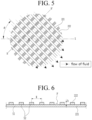
- FIG. 5 is a view showing a fluid guide unit 220 according to an embodiment of the present disclosure
- FIG. 6 is a sectional view taken along line B-B' of FIG. 5 .
- the fluid guide unit 220 uniformly guides the flow of a fluid through a dual-layer net structure.
- the fluid guide unit 220 includes a base unit 221 and a protrusion unit 222.
- the base unit 221 includes a plurality of first stripes S1 having a predetermined height (see FIG. 6 ), which wrap the circumference of the hollow fiber membranes 210 in the state of being spaced apart from each other by a predetermined distance.
- the base unit 221 performs a function of fixing and supporting the hollow fiber membranes 210 such that the hollow fiber membranes 210 do not shake.
- the protrusion unit 222 is formed on the base unit 221, and includes a plurality of second stripes S2 protruding from the base unit so as to have a predetermined size (see FIG. 6 ).
- the plurality of second stripes S2 are spaced apart from each other.
- the protrusion unit 222 uniformly guides the flow of a high-humidity fluid introduced into the hollow fiber membrane module 200.
- the flow of a high-humidity second fluid introduced through the second fluid inlet 131 is uniformly guided by the protrusion unit 222 before the second fluid flows outside the hollow fiber membranes 210, and then the second fluid exchanges moisture with a low-humidity first fluid flowing in the hollow fiber membranes 210 while flowing outside the hollow fiber membranes 210.
- the protrusion unit 222 is formed so as to have a predetermined height, interval, and angle in order to effectively control the flow direction of the high-humidity fluid.
- the protrusion unit 222 defines a flow channel F, and the height h of the protrusion unit 222 corresponds to the depth of the flow channel F.
- the height h of the protrusion unit 222 is formed so as to be equivalent to 50 to 300% of the diameter of a single hollow fiber membrane.
- the diameter of a single hollow fiber membrane may be, for example, about 1 mm, and therefore the height h of the protrusion unit 222 may be formed so as to have a size of 0.5 to 3 mm.
- the height h of the protrusion unit 222 is less than 50% of the diameter of a single hollow fiber membrane, a flow channel having a sufficient depth is not formed, whereby the fluid introduced into the hollow fiber membrane module 200 may not flow along the flow channel F and may then be discharged outside. Also, in the case in which the height h of the protrusion unit 222 is greater than 300% of the diameter of a single hollow fiber membrane, the effect is equal to the effect in the case in which the height of the protrusion unit is less than 300% of the diameter of a single hollow fiber membrane, and therefore this is not suitable for miniaturization.
- the interval W between the second stripes S2 constituting the protrusion unit 222 is formed so as to be equivalent to 50 to 300% of the diameter of a single hollow fiber membrane.
- the diameter of a single hollow fiber membrane may be, for example, about 1 mm, and therefore the interval W between the second stripes S2 may be formed so as to have a size of 0.5 to 3 mm.
- the interval W between the second stripes S2 is less than 50% of the diameter of a single hollow fiber membrane and in the case in which the interval W between the second stripes S2 is greater than 300% of the diameter of a single hollow fiber membrane, the interval is too small or too large, whereby the effect of adjusting the flow of a fluid is insignificant.
- each second stripe S2 constituting the protrusion unit 222 and the central axis X of the hollow fiber membrane module 200 ranges from 30 to 90°. In the case in which the angle ⁇ is less than 30°, there is a high possibility that the fluid introduced into the hollow fiber membrane module 200 will be directly discharged from the hollow fiber membrane module 200 while not sufficiently staying in the flow channel.
- the second to fourth quadrants in which the angle ⁇ ranges from 90 to 360° are identical to the first quadrant (in the case in which the angle ⁇ ranges from 0 to 90°) in the terms of a fluid, and therefore a description thereof will be omitted.
- the first fluid may be a low-humidity fluid
- the second fluid may be a high-humidity fluid
- the first fluid may be a high-humidity fluid
- the first fluid flows in the hollow fiber membranes 210 of the hollow fiber membrane module 200, and is then discharged from the membrane humidifier through the first fluid outlet 122 of the other housing cap 120. Meanwhile the first fluid may flow in the direction in which the first fluid is introduced through the first fluid outlet 122 and is then discharged through the first fluid inlet 121.
- the second fluid is supplied to the housing body 111 through the second fluid inlet 131 of the housing body 110, flows outside the hollow fiber membranes 210, and is then discharged outside through the second fluid outlet 132 of the housing body 110.
- the flow of the second fluid is uniformly guided by the second stripes constituting the protrusion unit 222 before the second fluid flows outside the hollow fiber membranes 210, and then the second fluid is introduced into spaces defined between the first stripes constituting the base unit 221, and flows outside the hollow fiber membranes 210, during which the second fluid exchanges moisture with the low-humidity first fluid flowing in the hollow fiber membranes 210.
- the flow of the fluid introduced into the hollow fiber membrane module 200 is uniformly guided by the protrusion unit of the fluid guide unit, whereby it is possible to improve humidification efficiency.
- housing unit 110 Housing body 120: Housing caps 200: Hollow fiber membrane module 210: Hollow fiber membranes 220: Fluid guide unit 221: Base unit 222: Protrusion unit
Description
- The present disclosure relates to a fuel cell membrane humidifier capable of controlling the flow direction of a fluid, thereby improving humidification efficiency.
- A fuel cell is a power generation cell that combines hydrogen and oxygen to generate electricity. Such a fuel cell has advantages in that it is possible to continuously generate electricity as long as hydrogen and oxygen are supplied, unlike a general chemical cell, such as a dry cell or a storage cell, and in that there is no heat loss, whereby efficiency of the fuel cell is about twice as high as efficiency of an internal combustion engine.
- In addition, the fuel cell directly converts chemical energy generated by combination of hydrogen and oxygen into electrical energy, whereby the amount of contaminants that are discharged is small. Consequently, the fuel cell has advantages in that the fuel cell is environmentally friendly and in that a concern about depletion of resources due to an increase in energy consumption can be reduced.
- Based on the kind of an electrolyte that is used, such a fuel cell may be classified as a polymer electrolyte membrane fuel cell (PEMFC), a phosphoric acid fuel cell (PAFC), a molten carbonate fuel cell (MCFC), a solid oxide fuel cell (SOFC), or an alkaline fuel cell (AFC).
- These fuel cells are operated fundamentally by the same principle, but are different from each other in terms of the kind of fuel that is used, operating temperature, catalyst, and electrolyte. Among these fuel cells, the polymer electrolyte membrane fuel cell is known as being the most favorable to a transportation system as well as small-scale stationary power generation equipment, since the polymer electrolyte membrane fuel cell is operated at a lower temperature than the other fuel cells and the output density of the polymer electrolyte membrane fuel cell is high, whereby it is possible to miniaturize the polymer electrolyte membrane fuel cell.
- One of the most important factors that improve the performance of the polymer electrolyte membrane fuel cell is to supply a predetermined amount or more of moisture to a polymer electrolyte membrane or a proton exchange membrane (PEM) of a membrane electrode assembly (MEA) in order to retain water content. The reason for this is that, in the case in which the polymer electrolyte membrane or the proton exchange membrane is dried, power generation efficiency is abruptly reduced.
- 1) A bubbler humidification method of filling a pressure-resistant container with water and allowing a target gas to pass through a diffuser in order to supply moisture, 2) a direct injection method of calculating the amount of moisture to be supplied that is necessary for fuel cell reaction and directly supplying moisture to a gas flowing pipe through a solenoid valve, and 3) a humidification membrane method of supplying moisture to a gas flowing layer using a polymer separation membrane are used as methods of humidifying the polymer electrolyte membrane or the proton exchange membrane.
- Among these methods, the humidification membrane method, which provides water vapor to a gas that is supplied to the polymer electrolyte membrane or the proton exchange membrane using a membrane configured to selectively transmit only water vapor included in an exhaust gas in order to humidify the polymer electrolyte membrane or the proton exchange membrane, is advantageous in that it is possible to reduce the weight and size of a humidifier.
- In the case in which a module is formed, a hollow fiber membrane having large transmission area per unit volume is preferably used as the selective transmission membrane used in the humidification membrane method. That is, in the case in which a humidifier is manufactured using a hollow fiber membrane, high integration of the hollow fiber membrane having large contact surface area is possible, whereby it is possible to sufficiently humidify a fuel cell even in the case of a small capacity, it is possible to use a low-priced material, and it is possible to collect moisture and heat included in a non-reaction gas discharged from the fuel cell at a high temperature and to reuse the collected moisture and heat through the humidifier.
- Meanwhile, in the case of a hollow fiber membrane having large transmission area per unit volume, high integration of the hollow fiber membrane is possible, whereby it is possible to sufficiently humidify a fuel cell even in the case of a small capacity. In the case in which the hollow fiber membrane is highly integrated, however, a fluid does not uniformly flow outside the hollow fiber membrane due to resistance of the hollow fiber membrane.
- In addition, since the flow of the fluid is not uniform, the area of the membrane that is used is reduced and thus only a portion of the membrane is used, whereby humidification efficiency is reduced.
-
JP 2008 309371 A US 2010/068603 A1 relates to a technique of transporting a fluid component between fluids with hollow fiber membranes.EP 2 827 073 A1 - The present disclosure has been made in view of the above problems, and it is an object of the present disclosure to provide a fuel cell membrane humidifier capable of uniformly controlling the flow of a fluid and guiding the fluid to unused humidification membranes even in the case in which hollow fiber membranes are highly integrated, thereby improving humidification efficiency.
- The above problems are solved by the appended claims.
- According to the embodiment of the present disclosure, the flow of the fluid introduced into the hollow fiber membrane module is guided uniformly or in a desired direction by the protrusion unit of the fluid guide unit, whereby it is possible to improve humidification efficiency.
- In addition, the dual-layer net structure constituted by the base unit and the protrusion unit, each of which has a predetermined height, is formed between the hollow fiber membranes and the housing unit in order to prevent direct contact between the hollow fiber membranes and the inner wall of the housing unit, whereby it is possible to prevent damage to the hollow fiber membranes due to the inner wall of the housing unit.
-
-
FIG. 1 is a view showing a fuel cell membrane humidifier according to an embodiment of the present disclosure. -
FIG. 2 is a view showing a modification of the fuel cell membrane humidifier according to the embodiment of the present disclosure. -
FIG. 3 is a view showing a hollow fiber membrane module of the fuel cell membrane humidifier according to the embodiment of the present disclosure. -
FIG. 4 is a sectional view taken along line A-A' ofFIG. 3 . -
FIG. 5 is a view showing a fluid guide unit according to an embodiment of the present disclosure. -
FIG. 6 is a sectional view taken along line B-B' ofFIG. 5 . - The present disclosure may be changed in various manners and may have various embodiments, wherein specific embodiments will be illustrated and described in detail in the following detailed description. However, the present disclosure is not limited to the specific embodiments, and it should be understood that the present disclosure includes all modifications, equivalents, or substitutions included in the idea and technical scope of the present disclosure.
- The terms used in the present disclosure are provided only to describe the specific embodiments, and do not limit the present disclosure. Singular forms are intended to include plural forms as well, unless the context clearly indicates otherwise. In the present disclosure, it should be understood that the terms "includes," "has," etc. specify the presence of features, numbers, steps, operations, elements, components, or combinations thereof described in the specification, but do not preclude the presence or addition of one or more other features, numbers, steps, operations, elements, components, or combinations thereof. Hereinafter, a hollow fiber membrane module including hollow fiber membranes made of different materials according to an embodiment of the present disclosure and a fuel cell membrane humidifier including the same will be described with reference to the accompanying drawings.
-
FIG. 1 is a view showing a fuel cell membrane humidifier according to an embodiment of the present disclosure, andFIG. 2 is a view showing a modification of the fuel cell membrane humidifier according to the embodiment of the present disclosure. - As shown in
FIGS. 1 and 2 , the fuel cell membrane humidifier according to the embodiment of the present disclosure includes ahousing unit 100 and a hollowfiber membrane module 200. - The
housing unit 100 defines the external appearance of the membrane humidifier. Thehousing unit 100 may include ahousing body 110 andhousing caps 120, which may be coupled to each other in order to constitute an integrated housing unit. Each of thehousing body 110 and thehousing caps 120 may be made of hard plastic, such as polycarbonate, or metal. - In addition, the lateral sectional shape of each of the
housing body 110 and thehousing caps 120 may be a circle, as shown inFIG. 1 , or the lateral sectional shape thereof may be a polygon, as shown inFIG. 2 . The polygon may be a rectangle, a square, a trapezoid, a parallelogram, a pentagon, or a hexagon, and corners of the polygon may be round. In addition, the circle may be an oval. - The
housing body 110 is provided at opposite ends thereof with asecond fluid inlet 131, through which a second fluid is supplied, and asecond fluid outlet 132, through which the second fluid is discharged. A first fluid may be a low-humidity fluid, and the second fluid may be a high-humidity fluid. Alternatively, the second fluid may be a low-humidity fluid, and the first fluid may be a high-humidity fluid. - The
housing caps 120 are coupled to opposite ends of thehousing body 110. Thehousing caps 120 are provided with afirst fluid inlet 121 and afirst fluid outlet 122, respectively. A first fluid introduced through thefirst fluid inlet 121 of one of thehousing caps 120 is introduced into the hollowfiber membrane module 200, passes through an inner pipeline of each hollow fiber membrane, flows out of the hollowfiber membrane module 200, and is discharged outside through thefirst fluid outlet 122 of theother housing cap 120. - A plurality of bundles of
hollow fiber membranes 210 configured to selectively transmit moisture may be disposed in the hollowfiber membrane module 200. Each bundle of hollow fiber membranes may be disposed in the form of a cartridge. - The
hollow fiber membranes 210 may be hollow fiber membranes made of, for example, Nafion, polyetherimide, or polyphenylsulfone. - A
fluid guide unit 220 configured to uniformly guide the flow of a fluid is formed around thehollow fiber membranes 210. Here, the fluid may be a high-humidity fluid. Thefluid guide unit 220 will be described later with reference toFIGS. 3 to 6 . - The hollow
fiber membrane module 200 is provided at opposite ends thereof with potting units (not shown) configured to bind thehollow fiber membranes 210 and thefluid guide unit 220 and to fill gaps between the hollow fiber membranes. As a result, the opposite ends of the hollowfiber membrane module 200 are blocked by the potting units, whereby a flow channel configured to allow the second fluid to pass therethrough is defined in the hollow fiber membrane module. Each of the potting units is made of a known material, and a detailed description thereof will be omitted from this specification. -
FIG. 3 is a view showing the hollow fiber membrane module of the fuel cell membrane humidifier according to the embodiment of the present disclosure,FIG. 4 is a sectional view taken along line A-A' ofFIG. 3 ,FIG. 5 is a view showing afluid guide unit 220 according to an embodiment of the present disclosure, andFIG. 6 is a sectional view taken along line B-B' ofFIG. 5 . - As shown in
FIGS. 3 and 4 , thefluid guide unit 220 uniformly guides the flow of a fluid through a dual-layer net structure. Thefluid guide unit 220 includes abase unit 221 and aprotrusion unit 222. - The
base unit 221 includes a plurality of first stripes S1 having a predetermined height (seeFIG. 6 ), which wrap the circumference of thehollow fiber membranes 210 in the state of being spaced apart from each other by a predetermined distance. Thebase unit 221 performs a function of fixing and supporting thehollow fiber membranes 210 such that thehollow fiber membranes 210 do not shake. - The
protrusion unit 222 is formed on thebase unit 221, and includes a plurality of second stripes S2 protruding from the base unit so as to have a predetermined size (seeFIG. 6 ). The plurality of second stripes S2 are spaced apart from each other. Theprotrusion unit 222 uniformly guides the flow of a high-humidity fluid introduced into the hollowfiber membrane module 200. For example, the flow of a high-humidity second fluid introduced through the secondfluid inlet 131 is uniformly guided by theprotrusion unit 222 before the second fluid flows outside thehollow fiber membranes 210, and then the second fluid exchanges moisture with a low-humidity first fluid flowing in thehollow fiber membranes 210 while flowing outside thehollow fiber membranes 210. - The
protrusion unit 222 is formed so as to have a predetermined height, interval, and angle in order to effectively control the flow direction of the high-humidity fluid. - Referring to
FIGS. 5 and 6 , theprotrusion unit 222 defines a flow channel F, and the height h of theprotrusion unit 222 corresponds to the depth of the flow channel F. - Preferably, the height h of the
protrusion unit 222 is formed so as to be equivalent to 50 to 300% of the diameter of a single hollow fiber membrane. Here, the diameter of a single hollow fiber membrane may be, for example, about 1 mm, and therefore the height h of theprotrusion unit 222 may be formed so as to have a size of 0.5 to 3 mm. - In the case in which the height h of the
protrusion unit 222 is less than 50% of the diameter of a single hollow fiber membrane, a flow channel having a sufficient depth is not formed, whereby the fluid introduced into the hollowfiber membrane module 200 may not flow along the flow channel F and may then be discharged outside. Also, in the case in which the height h of theprotrusion unit 222 is greater than 300% of the diameter of a single hollow fiber membrane, the effect is equal to the effect in the case in which the height of the protrusion unit is less than 300% of the diameter of a single hollow fiber membrane, and therefore this is not suitable for miniaturization. - Preferably, the interval W between the second stripes S2 constituting the
protrusion unit 222 is formed so as to be equivalent to 50 to 300% of the diameter of a single hollow fiber membrane. Here, the diameter of a single hollow fiber membrane may be, for example, about 1 mm, and therefore the interval W between the second stripes S2 may be formed so as to have a size of 0.5 to 3 mm. - In the case in which the interval W between the second stripes S2 is less than 50% of the diameter of a single hollow fiber membrane and in the case in which the interval W between the second stripes S2 is greater than 300% of the diameter of a single hollow fiber membrane, the interval is too small or too large, whereby the effect of adjusting the flow of a fluid is insignificant.
- The angle θ between each second stripe S2 constituting the
protrusion unit 222 and the central axis X of the hollow fiber membrane module 200 (seeFIGS. 3 and5 ) ranges from 30 to 90°. In the case in which the angle θ is less than 30°, there is a high possibility that the fluid introduced into the hollowfiber membrane module 200 will be directly discharged from the hollowfiber membrane module 200 while not sufficiently staying in the flow channel. Meanwhile, in axis symmetry based on the X axis or in point symmetry based on the point O, the second to fourth quadrants in which the angle θ ranges from 90 to 360° are identical to the first quadrant (in the case in which the angle θ ranges from 0 to 90°) in the terms of a fluid, and therefore a description thereof will be omitted. - Next, a process of moisture exchange between the first fluid and the second fluid in the membrane humidifier constructed as described above will be described. In the following description, the first fluid may be a low-humidity fluid, and the second fluid may be a high-humidity fluid. Alternatively, the second fluid may be a low-humidity fluid, and the first fluid may be a high-humidity fluid.
- The first fluid flows in the
hollow fiber membranes 210 of the hollowfiber membrane module 200, and is then discharged from the membrane humidifier through the firstfluid outlet 122 of theother housing cap 120. Meanwhile the first fluid may flow in the direction in which the first fluid is introduced through the firstfluid outlet 122 and is then discharged through the firstfluid inlet 121. - The second fluid is supplied to the housing body 111 through the second
fluid inlet 131 of thehousing body 110, flows outside thehollow fiber membranes 210, and is then discharged outside through the secondfluid outlet 132 of thehousing body 110. - At this time, the flow of the second fluid is uniformly guided by the second stripes constituting the
protrusion unit 222 before the second fluid flows outside thehollow fiber membranes 210, and then the second fluid is introduced into spaces defined between the first stripes constituting thebase unit 221, and flows outside thehollow fiber membranes 210, during which the second fluid exchanges moisture with the low-humidity first fluid flowing in thehollow fiber membranes 210. - According to the embodiment of the present disclosure described above, the flow of the fluid introduced into the hollow
fiber membrane module 200 is uniformly guided by the protrusion unit of the fluid guide unit, whereby it is possible to improve humidification efficiency. - In addition, the dual-layer net structure constituted by the base unit and the protrusion unit, each of which has a predetermined height, is formed between the hollow fiber membranes and the housing unit in order to prevent direct contact between the hollow fiber membranes and the inner wall of the housing unit, whereby it is possible to prevent damage to the hollow fiber membranes due to the inner wall of the housing unit.
[Description of Reference Numerals] 100: Housing unit 110: Housing body 120: Housing caps 200: Hollow fiber membrane module 210: Hollow fiber membranes 220: Fluid guide unit 221: Base unit 222: Protrusion unit
Claims (2)
- A membrane humidifier for a fuel cell, the membrane humidifier comprising:a hollow fiber membrane module (200) configured to receive hollow fiber membranes (210), in which a first fluid flows and outside which a second fluid flows such that the first fluid and the second fluid exchanges moisture with each other; anda housing unit (100) defining an external appearance of the membrane humidifier,characterized in that:a fluid guide unit (220) configured to uniformly guide a flow of the second fluid is formed between the hollow fiber membranes (210) and the housing unit (100);the fluid guide unit (220) has a dual-layer net structure and comprises a base unit (221) configured to wrap the hollow fiber membranes (210) and a protrusion unit (222) formed on the base unit (221), the protrusion unit (222) protruding so as to have a predetermined size;the base unit (221) comprises a plurality of first stripes (S1) spaced apart from each other;the protrusion unit (222) comprises a plurality of second stripes (S2) spaced apart from each other; andan angle defined between each of the plurality of second stripes (S2) and a central axis of the hollow fiber membrane module (200) ranges from 30 to 90°.
- The membrane humidifier according to claim 1, wherein the second fluid has higher humidity than the first fluid.
Applications Claiming Priority (3)
| Application Number | Priority Date | Filing Date | Title |
|---|---|---|---|
| KR1020170184479A KR102216355B1 (en) | 2017-12-29 | 2017-12-29 | Fuel cell membrane humidifier capable of controlling flow direction of fluid |
| PCT/KR2018/016895 WO2019132606A1 (en) | 2017-12-29 | 2018-12-28 | Fuel cell membrane humidifier capable of controlling flow direction of fluid |
| EP18894299.9A EP3734730B1 (en) | 2017-12-29 | 2018-12-28 | Fuel cell membrane humidifier capable of controlling flow direction of fluid |
Related Parent Applications (2)
| Application Number | Title | Priority Date | Filing Date |
|---|---|---|---|
| EP18894299.9A Division EP3734730B1 (en) | 2017-12-29 | 2018-12-28 | Fuel cell membrane humidifier capable of controlling flow direction of fluid |
| EP18894299.9A Division-Into EP3734730B1 (en) | 2017-12-29 | 2018-12-28 | Fuel cell membrane humidifier capable of controlling flow direction of fluid |
Publications (2)
| Publication Number | Publication Date |
|---|---|
| EP4009405A1 EP4009405A1 (en) | 2022-06-08 |
| EP4009405B1 true EP4009405B1 (en) | 2024-01-31 |
Family
ID=67063947
Family Applications (3)
| Application Number | Title | Priority Date | Filing Date |
|---|---|---|---|
| EP18894299.9A Active EP3734730B1 (en) | 2017-12-29 | 2018-12-28 | Fuel cell membrane humidifier capable of controlling flow direction of fluid |
| EP22154670.8A Active EP4009405B1 (en) | 2017-12-29 | 2018-12-28 | Fuel cell membrane humidifier capable of controlling flow direction of fluid |
| EP22154668.2A Active EP4033576B1 (en) | 2017-12-29 | 2018-12-28 | Fuel cell membrane humidifier capable of controlling flow direction of fluid |
Family Applications Before (1)
| Application Number | Title | Priority Date | Filing Date |
|---|---|---|---|
| EP18894299.9A Active EP3734730B1 (en) | 2017-12-29 | 2018-12-28 | Fuel cell membrane humidifier capable of controlling flow direction of fluid |
Family Applications After (1)
| Application Number | Title | Priority Date | Filing Date |
|---|---|---|---|
| EP22154668.2A Active EP4033576B1 (en) | 2017-12-29 | 2018-12-28 | Fuel cell membrane humidifier capable of controlling flow direction of fluid |
Country Status (6)
| Country | Link |
|---|---|
| US (1) | US11469428B2 (en) |
| EP (3) | EP3734730B1 (en) |
| KR (1) | KR102216355B1 (en) |
| CN (1) | CN111527634B (en) |
| TW (1) | TWI686006B (en) |
| WO (1) | WO2019132606A1 (en) |
Families Citing this family (3)
| Publication number | Priority date | Publication date | Assignee | Title |
|---|---|---|---|---|
| EP4027418A4 (en) * | 2020-09-14 | 2024-02-21 | Kolon Inc | Fuel cell membrane humidifier and fuel cell system including same |
| CN114050291A (en) * | 2021-11-15 | 2022-02-15 | 上海重塑能源科技有限公司 | Humidifier for fuel cell system and debugging and working method thereof |
| WO2024029758A1 (en) * | 2022-08-04 | 2024-02-08 | 코오롱인더스트리 주식회사 | Cartridge for fuel cell humidifier, and fuel cell humidifier |
Family Cites Families (25)
| Publication number | Priority date | Publication date | Assignee | Title |
|---|---|---|---|---|
| GB2324214A (en) | 1997-04-08 | 1998-10-14 | Power X Limited | Synchronising arrangements |
| RU2219679C2 (en) | 1997-04-14 | 2003-12-20 | Томсон Конзьюмер Электроникс, Инк. | System for user-requested data acquisition through program pointer choice |
| KR100316710B1 (en) | 1999-06-01 | 2001-12-12 | 윤종용 | Method and Apparatus for Instruction issuing in Out-of-Order for Parallel Processor |
| JP3777893B2 (en) | 1999-08-05 | 2006-05-24 | セイコーエプソン株式会社 | Liquid crystal display |
| KR20010026696A (en) | 1999-09-08 | 2001-04-06 | 이중구 | Method for automatically measuring line of balance and apparatus thereof |
| KR100394827B1 (en) | 1999-12-22 | 2003-08-21 | 엘지전자 주식회사 | Program and data down loading method for restating processor of mobile communication exchage system |
| JP2001202977A (en) * | 2000-01-19 | 2001-07-27 | Honda Motor Co Ltd | Humidifier |
| US6653012B2 (en) | 2000-01-19 | 2003-11-25 | Honda Giken Kogyo Kabushiki Kaisha | Humidifier |
| JP2002358988A (en) * | 2001-06-01 | 2002-12-13 | Honda Motor Co Ltd | Hollow fiber module |
| JP4211290B2 (en) | 2002-05-31 | 2009-01-21 | Nok株式会社 | Humidifier for fuel cell |
| JP5074743B2 (en) * | 2006-11-13 | 2012-11-14 | トヨタ自動車株式会社 | Hollow fiber membrane module, fuel cell system |
| JP2008309371A (en) * | 2007-06-13 | 2008-12-25 | Toyota Motor Corp | Humidifier and fuel cell system |
| KR101278398B1 (en) | 2007-08-01 | 2013-06-24 | 코오롱인더스트리 주식회사 | Hollow Fiber Membrane and Method for Manufacturing The Same |
| KR101398779B1 (en) | 2007-12-03 | 2014-05-28 | 코오롱인더스트리 주식회사 | Fuel Cell Humidifier with Improved Cold Resistance |
| KR101000650B1 (en) * | 2008-03-06 | 2010-12-10 | 기아자동차주식회사 | Humidification device for fuel cell |
| KR20090128005A (en) | 2008-06-10 | 2009-12-15 | 주식회사 코오롱 | Humidification system for fuel cell and fuel cell system using the same |
| JP5350966B2 (en) * | 2009-10-01 | 2013-11-27 | 本田技研工業株式会社 | Humidification module |
| KR101337904B1 (en) * | 2011-09-14 | 2013-12-09 | 기아자동차주식회사 | Humidification device for fuel cell |
| EP2827073A4 (en) * | 2012-03-13 | 2015-04-15 | Nissan Motor | Humidifier |
| KR102002386B1 (en) * | 2013-04-18 | 2019-07-23 | 코오롱인더스트리 주식회사 | Hollow fiber membrane module |
| KR101993237B1 (en) * | 2013-09-30 | 2019-06-26 | 코오롱인더스트리 주식회사 | Fluid exchange membrane module |
| KR101984034B1 (en) | 2014-03-24 | 2019-05-30 | 코오롱인더스트리 주식회사 | Hollow fiber membrane module |
| US20160310903A1 (en) * | 2015-04-22 | 2016-10-27 | Mann+Hummel Gmbh | Hollow Fiber Module, Fluid Treatment Device, and Method of Forming a Hollow Fiber Module |
| KR101766011B1 (en) | 2015-04-30 | 2017-08-07 | 현대자동차주식회사 | Humidification device for fuel cell |
| US10840521B2 (en) * | 2015-12-30 | 2020-11-17 | Mann+Hummel Gmbh | Humidifier, for example for a fuel cell |
-
2017
- 2017-12-29 KR KR1020170184479A patent/KR102216355B1/en active IP Right Grant
-
2018
- 2018-12-04 TW TW107143339A patent/TWI686006B/en active
- 2018-12-28 EP EP18894299.9A patent/EP3734730B1/en active Active
- 2018-12-28 WO PCT/KR2018/016895 patent/WO2019132606A1/en unknown
- 2018-12-28 US US16/958,340 patent/US11469428B2/en active Active
- 2018-12-28 CN CN201880084789.XA patent/CN111527634B/en active Active
- 2018-12-28 EP EP22154670.8A patent/EP4009405B1/en active Active
- 2018-12-28 EP EP22154668.2A patent/EP4033576B1/en active Active
Also Published As
| Publication number | Publication date |
|---|---|
| EP3734730A1 (en) | 2020-11-04 |
| KR102216355B1 (en) | 2021-02-16 |
| EP4033576B1 (en) | 2023-08-09 |
| TWI686006B (en) | 2020-02-21 |
| TW201931652A (en) | 2019-08-01 |
| WO2019132606A1 (en) | 2019-07-04 |
| CN111527634A (en) | 2020-08-11 |
| EP4033576A1 (en) | 2022-07-27 |
| EP3734730A4 (en) | 2021-07-28 |
| US20210066733A1 (en) | 2021-03-04 |
| EP4009405A1 (en) | 2022-06-08 |
| KR20190081735A (en) | 2019-07-09 |
| EP3734730B1 (en) | 2023-09-20 |
| CN111527634B (en) | 2023-05-16 |
| US11469428B2 (en) | 2022-10-11 |
Similar Documents
| Publication | Publication Date | Title |
|---|---|---|
| EP3312923B1 (en) | Hollow fiber membrane module | |
| US20210151780A1 (en) | Membrane humidifier for fuel cell | |
| KR102170523B1 (en) | Fuel cell membrane humidifier | |
| US11831047B2 (en) | Membrane humidifier for fuel cell, and fuel cell system comprising same | |
| KR20140125098A (en) | Hollow fiber membrane module | |
| EP4009405B1 (en) | Fuel cell membrane humidifier capable of controlling flow direction of fluid | |
| US10478779B2 (en) | Hollow fiber membrane module | |
| US11607648B2 (en) | Assembly-type cartridge block and hollow-fiber membrane module comprising same | |
| KR102248995B1 (en) | Hollow fiber cartridge capable of controlling flow direction of fluid and fuel cell membrane humidifier comprising it | |
| KR102017256B1 (en) | Fluid exchange membrane module | |
| KR102204066B1 (en) | Hollow fiber membrane module with hollow fiber membrane of different material and fuel cell membrane humidifier comprising thereof | |
| KR102068135B1 (en) | Hollow fiber membrane module | |
| KR20220043352A (en) | Cartridge of Humidifier for Fuel Cell and Humidifier for Fuel Cell | |
| US20240079613A1 (en) | Membrane humidifier for fuel cell | |
| JP2024514917A (en) | fuel cell membrane humidifier | |
| KR20220096814A (en) | Fuel cell humidifier | |
| CN117716549A (en) | Membrane humidifier cylinder and fuel cell membrane humidifier comprising same | |
| KR20220108568A (en) | Fuel cell membrane humidifier and fuel cell system comprising it | |
| KR20230033822A (en) | Fuel cell humidifier | |
| KR20230032780A (en) | Fuel cell humidifier | |
| KR20220089419A (en) | Cartridge and fuel cell humidifier comprising it | |
| KR20230032781A (en) | Fuel cell humidifier |
Legal Events
| Date | Code | Title | Description |
|---|---|---|---|
| PUAI | Public reference made under article 153(3) epc to a published international application that has entered the european phase |
Free format text: ORIGINAL CODE: 0009012 |
|
| STAA | Information on the status of an ep patent application or granted ep patent |
Free format text: STATUS: THE APPLICATION HAS BEEN PUBLISHED |
|
| AC | Divisional application: reference to earlier application |
Ref document number: 3734730 Country of ref document: EP Kind code of ref document: P |
|
| AK | Designated contracting states |
Kind code of ref document: A1 Designated state(s): AL AT BE BG CH CY CZ DE DK EE ES FI FR GB GR HR HU IE IS IT LI LT LU LV MC MK MT NL NO PL PT RO RS SE SI SK SM TR |
|
| STAA | Information on the status of an ep patent application or granted ep patent |
Free format text: STATUS: REQUEST FOR EXAMINATION WAS MADE |
|
| 17P | Request for examination filed |
Effective date: 20221118 |
|
| RBV | Designated contracting states (corrected) |
Designated state(s): AL AT BE BG CH CY CZ DE DK EE ES FI FR GB GR HR HU IE IS IT LI LT LU LV MC MK MT NL NO PL PT RO RS SE SI SK SM TR |
|
| GRAP | Despatch of communication of intention to grant a patent |
Free format text: ORIGINAL CODE: EPIDOSNIGR1 |
|
| STAA | Information on the status of an ep patent application or granted ep patent |
Free format text: STATUS: GRANT OF PATENT IS INTENDED |
|
| INTG | Intention to grant announced |
Effective date: 20230803 |
|
| GRAS | Grant fee paid |
Free format text: ORIGINAL CODE: EPIDOSNIGR3 |
|
| GRAA | (expected) grant |
Free format text: ORIGINAL CODE: 0009210 |
|
| STAA | Information on the status of an ep patent application or granted ep patent |
Free format text: STATUS: THE PATENT HAS BEEN GRANTED |
|
| AC | Divisional application: reference to earlier application |
Ref document number: 3734730 Country of ref document: EP Kind code of ref document: P |
|
| AK | Designated contracting states |
Kind code of ref document: B1 Designated state(s): AL AT BE BG CH CY CZ DE DK EE ES FI FR GB GR HR HU IE IS IT LI LT LU LV MC MK MT NL NO PL PT RO RS SE SI SK SM TR |
|
| REG | Reference to a national code |
Ref country code: GB Ref legal event code: FG4D Ref country code: CH Ref legal event code: EP |
|
| REG | Reference to a national code |
Ref country code: DE Ref legal event code: R096 Ref document number: 602018064870 Country of ref document: DE |
|
| REG | Reference to a national code |
Ref country code: IE Ref legal event code: FG4D |