EP3312852A1 - Electromagnetic actuator with ferromagnetic plunger - Google Patents
Electromagnetic actuator with ferromagnetic plunger Download PDFInfo
- Publication number
- EP3312852A1 EP3312852A1 EP17197640.0A EP17197640A EP3312852A1 EP 3312852 A1 EP3312852 A1 EP 3312852A1 EP 17197640 A EP17197640 A EP 17197640A EP 3312852 A1 EP3312852 A1 EP 3312852A1
- Authority
- EP
- European Patent Office
- Prior art keywords
- magnetic member
- ring coil
- ferromagnetic plunger
- longitudinal axis
- electromagnetic actuator
- Prior art date
- Legal status (The legal status is an assumption and is not a legal conclusion. Google has not performed a legal analysis and makes no representation as to the accuracy of the status listed.)
- Ceased
Links
- 230000005294 ferromagnetic effect Effects 0.000 title claims abstract description 81
- 230000005291 magnetic effect Effects 0.000 claims abstract description 124
- 238000000034 method Methods 0.000 claims description 37
- 230000008569 process Effects 0.000 description 6
- 230000004907 flux Effects 0.000 description 5
- 238000005265 energy consumption Methods 0.000 description 2
- 230000004323 axial length Effects 0.000 description 1
- 239000003990 capacitor Substances 0.000 description 1
- 230000008859 change Effects 0.000 description 1
- 238000013016 damping Methods 0.000 description 1
- 230000005347 demagnetization Effects 0.000 description 1
- 230000000694 effects Effects 0.000 description 1
- 230000005684 electric field Effects 0.000 description 1
- 239000012530 fluid Substances 0.000 description 1
- 239000000463 material Substances 0.000 description 1
- 238000005259 measurement Methods 0.000 description 1
- 238000012986 modification Methods 0.000 description 1
- 230000004048 modification Effects 0.000 description 1
Images

Classifications
-
- H—ELECTRICITY
- H01—ELECTRIC ELEMENTS
- H01F—MAGNETS; INDUCTANCES; TRANSFORMERS; SELECTION OF MATERIALS FOR THEIR MAGNETIC PROPERTIES
- H01F7/00—Magnets
- H01F7/06—Electromagnets; Actuators including electromagnets
- H01F7/08—Electromagnets; Actuators including electromagnets with armatures
- H01F7/16—Rectilinearly-movable armatures
- H01F7/1607—Armatures entering the winding
- H01F7/1615—Armatures or stationary parts of magnetic circuit having permanent magnet
-
- F—MECHANICAL ENGINEERING; LIGHTING; HEATING; WEAPONS; BLASTING
- F16—ENGINEERING ELEMENTS AND UNITS; GENERAL MEASURES FOR PRODUCING AND MAINTAINING EFFECTIVE FUNCTIONING OF MACHINES OR INSTALLATIONS; THERMAL INSULATION IN GENERAL
- F16K—VALVES; TAPS; COCKS; ACTUATING-FLOATS; DEVICES FOR VENTING OR AERATING
- F16K31/00—Actuating devices; Operating means; Releasing devices
- F16K31/02—Actuating devices; Operating means; Releasing devices electric; magnetic
- F16K31/06—Actuating devices; Operating means; Releasing devices electric; magnetic using a magnet, e.g. diaphragm valves, cutting off by means of a liquid
- F16K31/0675—Electromagnet aspects, e.g. electric supply therefor
- F16K31/0679—Electromagnet aspects, e.g. electric supply therefor with more than one energising coil
-
- H—ELECTRICITY
- H01—ELECTRIC ELEMENTS
- H01F—MAGNETS; INDUCTANCES; TRANSFORMERS; SELECTION OF MATERIALS FOR THEIR MAGNETIC PROPERTIES
- H01F7/00—Magnets
- H01F7/06—Electromagnets; Actuators including electromagnets
- H01F7/08—Electromagnets; Actuators including electromagnets with armatures
- H01F7/16—Rectilinearly-movable armatures
- H01F2007/1692—Electromagnets or actuators with two coils
Definitions
- the subject matter disclosed herein generally relates to an actuator system, and more specifically to an apparatus and a method for operating an electromagnetic actuator system.
- electromagnetic actuators utilize a permanent magnet plunger within an electric coil.
- the permanent magnet plunger within the electric coil form what may be commonly referred to as a solenoid. Electrical current flowing through the coil creates an electromagnetic force that causes the permanent magnet plunger to move axially within the coil.
- short-stroke electromagnetic actuators may be driven by the electromagnetic force from two solenoids.
- this type of actuator suffers the inherent problem of high-energy consumption for operation, which causes the actuator to increase in temperature.
- catching the plunger requires that a large amount of current be supplied to the solenoid in a reasonably short time.
- actuators with permanent magnet plungers may also suffer from demagnetization of permanent magnets due to vibration (high frequency vertical movement up and down).
- an electromagnetic actuator includes: a housing having a longitudinal axis; a first ring coil within the housing and coaxial to the longitudinal axis; a second ring coil within the housing and coaxial to the longitudinal axis; a first magnetic member within the housing and coaxial to the longitudinal axis; a second magnetic member within the housing and coaxial to the longitudinal axis; and a ferromagnetic plunger configured to fit within the first ring coil, the second ring coil, the first magnetic member, and the second magnetic member; wherein the first ring coil and the second ring coil are oriented in an alternating arrangement with the first magnetic member and the second magnetic member.
- further embodiments of the electromagnetic actuator may include that the second ring coil is interposed between the first magnetic member and the second magnetic member; and the first magnetic member is interposed between the first ring coil and the second ring coil.
- further embodiments of the electromagnetic actuator may include that the ferromagnetic plunger in operation moves in a first direction when first ring coil is energized and the ferromagnetic plunger in operation moves in a second direction when the second ring coil is energized.
- further embodiments of the electromagnetic actuator may include that the second direction is opposite the first direction; and the first direction and second direction are parallel to the longitudinal axis.
- further embodiments of the electromagnetic actuator may include that at least one of the first magnetic member and the second magnetic member holds the ferromagnetic plunger in place when the first ring coil and the second ring coil are not energized.
- further embodiments of the electromagnetic actuator may include a rod having a first end and an opposing second end, the first end being fixedly connected to the ferromagnetic plunger, wherein the rod in operation moves in unison with the ferromagnetic plunger.
- further embodiments of the electromagnetic actuator may include a valve control system operably connected to the rod proximate the second end, the valve control system in operation opens a valve when the ferromagnetic plunger moves in a second direction.
- a method of assembling an electromagnetic actuator includes: installing a first ring coil into a housing, the housing having a longitudinal axis and the first ring coil being coaxial to the longitudinal axis; installing a first magnetic member into the housing, the first magnetic member being coaxial to the longitudinal axis; installing a second ring coil into the housing, the second ring coil being coaxial to the longitudinal axis; installing a second magnetic member into the housing, the second magnetic member being coaxial to the longitudinal axis; and installing a ferromagnetic plunger within the first ring coil, the second ring coil, the first magnetic member, and the second magnetic member, the ferromagnetic plunger being coaxial to the longitudinal axis; wherein the first ring coil and the second ring coil are oriented in an alternating arrangement with the first magnetic member and the second magnetic member.
- further embodiments of the method of assembling the electromagnetic actuator may include that the second ring coil is interposed between the first magnetic member and the second magnetic member; and the first magnetic member is interposed between the first ring coil and the second ring coil.
- further embodiments of the method of assembling the electromagnetic actuator may include that the ferromagnetic plunger in operation moves in a first direction when first ring coil is energized and the ferromagnetic plunger in operation moves in a second direction when the second ring coil is energized.
- further embodiments of the method of assembling the electromagnetic actuator may include that the second direction is opposite the first direction; and the first direction and second direction are parallel to the longitudinal axis.
- further embodiments of the method of assembling the electromagnetic actuator may include that at least one of the first magnetic member and the second magnetic member holds the ferromagnetic plunger in place when the first ring coil and the second ring coil are not energized.
- further embodiments of the method of assembling the electromagnetic actuator may include fixedly connecting a rod to the ferromagnetic plunger, the rod having a first end and an opposing second end, wherein the first end is fixedly connected to the ferromagnetic plunger and the rod in operation moves in unison with the ferromagnetic plunger.
- further embodiments of the method of assembling the electromagnetic actuator may include operably connecting a valve control system to the rod proximate the second end, the valve control system in operation opens a valve when the ferromagnetic plunger moves in a second direction.
- a method of operating an electromagnetic actuator including: energizing a first ring coil that in operation generates a first electromagnetic force; moving a ferromagnetic plunger using the first electromagnetic force in a first direction from a first position to a second position; de-energizing the first ring coil when the ferromagnetic plunger is at the second position; and holding the ferromagnetic plunger at the second position for a first selected period of time using at least one of a first magnetic member and a second magnetic member.
- further embodiments of the method of operating the electromagnetic actuator may include: energizing a second ring coil that in operation generates a second electromagnetic force; moving a ferromagnetic plunger using the second electromagnetic force in a second direction from the second position to the first position; de-energizing the second ring coil when the ferromagnetic plunger is at the first position; and holding the ferromagnetic plunger at the second position for a second selected period of time using at least one of a first magnetic member and a second magnetic member.
- further embodiments of the method of operating the electromagnetic actuator may include that the second ring coil is interposed between the first magnetic member and the second magnetic member; and the first magnetic member is interposed between the first ring coil and the second ring coil.
- further embodiments of the method of operating the electromagnetic actuator may include that the ferromagnetic plunger is located within the first ring coil, the second ring, the first magnetic member, and the second magnetic member.
- further embodiments of the method of operating the electromagnetic actuator may include moving a rod having a first end and a second end when the ferromagnetic plunger moves, the first end being fixedly connected to the ferromagnetic plunger; wherein the rod in operation moves in unison with the ferromagnetic plunger.
- further embodiments of the method of operating the electromagnetic actuator may include closing a valve of a valve control system when ferromagnetic plunger moves to the second position, the valve control system being operably connected to the rod proximate the second end.
- inventions of the present disclosure include moving a ferromagnetic plunger between two positions utilizing alternating energization of at least two electrical coils and maintaining the position of the ferromagnetic plunger by deactivating the all electrical coils and utilizing permanent magnets.
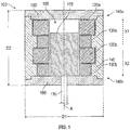
- the electromagnetic actuator 100 can be used to actuate a rod 170 in a first direction X1 and in a second direction X2 opposing the first direction X1.
- the electromagnetic actuator 100 is composed of a ferromagnetic plunger 110 enclosed within a first ring coil 120a, a second ring coil 120b, a first magnetic member 130a, and a second magnetic member 130b. As the ferromagnetic plunger 110 moves in the first direction X1 and second direction X2, the reluctance for magnetic flux changes.
- the ferromagnetic plunger 110 takes a position corresponding to minimal reluctance for the magnetic flux.
- the first ring coil 120a, the second ring coil 120b, the first magnetic member 130a, and the second magnetic member 130b are ring shaped and the ferromagnetic plunger 110 is cylindrical and configured to fit within the first ring coil 120a, the second ring coil 120b, the first magnetic member 130a, and the second magnetic member 130b.
- first ring coil 120a, the second ring coil 120b, the first magnetic member 130a, and the second magnetic member 130b are rectilinearly shaped (square, pentagon, hexagon, and so on and so forth) and the ferromagnetic plunger 110 is rectilinear and configured to fit within the first ring coil 120a, the second ring coil 120b, the first magnetic member 130a, and the second magnetic member 130b.
- the first ring coil 120a, the second ring coil 120b, the first magnetic member 130a, and the second magnetic member 130b are located within an inner chamber 190 of a housing 140.
- the housing 140 has a longitudinal axis A.
- the first ring coil 120a, the second ring coil 120b, the first magnetic member 130a, and the second magnetic member 130b are oriented coaxial to the longitudinal axis A within the inner chamber 190.
- the arrangement of the ring coils 120a, 120b along the longitudinal axis A alternates with the magnetic members 130a, 130b.
- This alternating arrangement means that the magnetic members 130a, 130b are separated by at least one ring coil and then the ring coils 120a, 120b are separated by at least one magnetic member.
- the second ring coil 120b is interposed between the first magnetic member 130a and the second magnetic member 130b and then subsequently the first magnetic member 130a may be interposed between the first ring coil 120a and the second ring coil 120b.
- the number of or specific arrangement of the ring coils and magnetic members may change as long as the alternating arrangement between ring coils and magnetic members is maintained.
- the first magnetic member 130a and the second magnetic member 130b are permanent magnets.
- the first magnetic member 130a and the second magnetic member 130b are electrical coils that generate an electrical field when energized (i.e. supplied with electrical current).
- the housing 140 defines the inner chamber 190.
- the housing 140 and the inner chamber 190 are cylindrical in shape.
- the housing 140 includes a first cover 150 located at a first end 140a of the housing 140 and a second cover 160 located at a second end 140b of the housing 140 to enclose the inner chamber 190 at both ends 140a, 140b of the housing 140, as seen in FIG. 1 .
- One of the covers may include a hole through which the rod 170 may fixedly connect to the ferromagnetic plunger 110.
- the rod includes a first end 170a and an opposing second end 170b.
- the first end 170a is fixedly connected to the ferromagnetic plunger 110.
- the rod 170 is oriented parallel with the longitudinal axis A. As the ferromagnetic plunger 110 moves in either direction X1 or direction X2, the rod 170 will move with the ferromagnetic plunger 110.
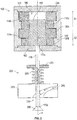
- the rod 170 may be operably connected to a valve control system 200 proximate the second end 170b.
- the valve control system 200 can be used to open and close a valve 230 as the rod 170 moves in the second direction X2 and the first direction X1.
- the valve control system 200 includes a valve cover 260 fixedly attached to the rod 170, a moving collar 250 operably connected to the rod 170, and a spring 220 located between the collar 250 and a valve housing 270.
- the valve 230 will open allowing a fluid 240 to move through the valve 230.
- the spring 220 may provide a damping force to the motion of the rod 170 and/or a force to help move the rod 170 in the first direction X1 and close the valve 230.
- the compact design of the electromagnetic actuator 100 in the present disclosure allows for a high force density.
- the electromagnetic actuator 100 may have an outer diameter D1 of about 48 millimeters (1.88976 inches), an axial length D2 of about 43 millimeters (1.69291 inches), and produces a force on the rod 170 of about 319 newtons (71.7141 pound-force), which means that the electromagnetic actuator 100 has a force density of about 4.0 x 10⁶ N/m3 (2.61 x 10⁴ lbf/ft3).
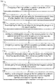
- FIG. 3 shows a flow process illustrating a method 300 of operating the electromagnetic actuator 100 of FIGs. 1-2 , according to an embodiment of the present disclosure.
- the ferromagnetic plunger 110 moves in the first direction X1 and second direction X2, the reluctance for magnetic flux changes.
- the ferromagnetic plunger 110 takes a position corresponding to minimal reluctance for the magnetic flux.
- the ferromagnetic plunger 110 starts in a first position 110a proximate the second cover 160, as seen in FIG. 2 .
- the first ring coil 120a is energized (i.e. supplied with electrical current).
- a first electromagnetic force is generated.
- the ferromagnetic plunger 110 will take a position corresponding to minimal reluctance for magnetic flux.
- the electromagnetic force is generated by the first ring coil 120a the ferromagnetic plunger 110 will move in the first direction X1 from the first position 110a to a second position 110b at block 306, as seen in FIG. 2 .
- the first ring coil 120a is de-energized (i.e. electrical current is removed).
- the ferromagnetic plunger 110 is held at the second position 110b for a first selected period of time using at least one of the first magnetic member 130a and the second magnetic member 130b.
- the first magnetic member 130a and the second magnetic member 130b are permanent magnets
- the magnetic field of at least one of the first magnetic member 130a and the second magnetic member 130b would hold the ferromagnetic plunger at the second position.
- the first magnetic member 130a and the second magnetic member 130b are electrical coils
- at least one of the first magnetic member 130a and the second magnetic member 130b would have to be energized to generate a magnetic field and hold the ferromagnetic plunger at the second position.
- the second ring coil 120b is energized (i.e. supplied with electrical current).
- a second electromagnetic force is generated.
- the ferromagnetic plunger 110 will move in the second direction X2 from the second position 110b to the first position 110a at block 314.
- the second ring coil 120b is de-energized (i.e. electrical current is removed).
- the ferromagnetic plunger 110 is held at the first position 110a for a second selected period of time using at least one of the first magnetic member 130a and the second magnetic member 130b.
- the magnetic field of at least one of the first magnetic member 130a and the second magnetic member 130b would hold the ferromagnetic plunger at the first position.
- the first magnetic member 130a and the second magnetic member 130b are electrical coils, at least one of the first magnetic member 130a and the second magnetic member 130b would have to be energized to generate a magnetic field and hold the ferromagnetic plunger at the first position.
- the ferromagnetic plunger 110 may be fixedly attached to a rod 170 and the rod 170 may be operably connected to a valve control system 200 as seen in FIG. 2 and described above.
- a valve control system 200 as seen in FIG. 2 and described above, as the ferromagnetic plunger 110 moves in the first direction X1 from the first position 110a to the second position the valve 230 may close and as the ferromagnetic plunger 110 moves in the second direction X2 from the second position 110b to the first position 110a the valve 230 may open.
- the valve 230 may open and as the ferromagnetic plunger 110 moves in the second direction X2 from the second position 110b to the first position 110a the valve 230 may close.
- the ferromagnetic plunger 110 may be utilized for any short stroke and/or high load actuator application, such as, for example aircraft control surfaces, reciprocating pumps, and reciprocating compressors.
- the electromagnetic actuator 100 could be energized with short-time current pulses resulting in low energy consumption and low joule losses. Also advantageously, by energizing the ring coils 120a, 120b with short term pulses, it allows increase controllability of the electromagnetic actuator 100.
- the short-time current pulses may be between about 4 - 10 milliseconds. In another embodiment, the short-time current pulses may be released from a capacitor.
- FIG. 4 shows a flow process illustrating a method 400 of assembling the electromagnetic actuator 100 of FIGs. 1-2 , according to an embodiment of the present disclosure.
- the first ring coil 120a is installed into the housing 140.
- the housing 140 has a longitudinal axis A as described above and the first ring coil 120a is coaxial to the longitudinal axis A.
- the first magnetic member 130a is installed into the housing 140.
- the first magnetic member 130a is coaxial to the longitudinal axis A.
- the second ring coil 120b is installed into the housing 140.
- the second ring coil 120b is coaxial to the longitudinal axis A.
- the second magnetic member 130b is installed into the housing 140.
- the second magnetic member 130b is coaxial to the longitudinal axis A.
- the ferromagnetic plunger 110 is installed within the first ring coil 120a, the second ring coil 120b, the first magnetic member 130a, and the second magnetic member 130b.
- the ferromagnetic plunger 110 is coaxial to the longitudinal axis A.
- the method 400 may include fixedly connecting a rod 170 to the ferromagnetic plunger 110.
- the rod 170 had a first end 170a and an opposing second end 170b.
- the first end 170a is fixedly connected to the ferromagnetic plunger 110 and the rod 170 in operation moves in unison with the ferromagnetic plunger 110.
- the method 400 may also include operably connecting a valve control system 200 to the rod 170 proximate the second end 170b.
- the valve control system 200 may in operation open a valve 230 when the ferromagnetic plunger 110 moves in the second direction X2.
Landscapes
- Physics & Mathematics (AREA)
- Electromagnetism (AREA)
- Engineering & Computer Science (AREA)
- General Engineering & Computer Science (AREA)
- Power Engineering (AREA)
- Mechanical Engineering (AREA)
- Magnetically Actuated Valves (AREA)
- Electromagnets (AREA)
Abstract
Description
- The subject matter disclosed herein generally relates to an actuator system, and more specifically to an apparatus and a method for operating an electromagnetic actuator system.
- Commonly electromagnetic actuators utilize a permanent magnet plunger within an electric coil. The permanent magnet plunger within the electric coil form what may be commonly referred to as a solenoid. Electrical current flowing through the coil creates an electromagnetic force that causes the permanent magnet plunger to move axially within the coil. In an example, short-stroke electromagnetic actuators may be driven by the electromagnetic force from two solenoids. However, this type of actuator suffers the inherent problem of high-energy consumption for operation, which causes the actuator to increase in temperature. In addition, catching the plunger requires that a large amount of current be supplied to the solenoid in a reasonably short time. Also, actuators with permanent magnet plungers may also suffer from demagnetization of permanent magnets due to vibration (high frequency vertical movement up and down).
- According to one embodiment, an electromagnetic actuator is provided. The electromagnetic actuator includes: a housing having a longitudinal axis; a first ring coil within the housing and coaxial to the longitudinal axis; a second ring coil within the housing and coaxial to the longitudinal axis; a first magnetic member within the housing and coaxial to the longitudinal axis; a second magnetic member within the housing and coaxial to the longitudinal axis; and a ferromagnetic plunger configured to fit within the first ring coil, the second ring coil, the first magnetic member, and the second magnetic member; wherein the first ring coil and the second ring coil are oriented in an alternating arrangement with the first magnetic member and the second magnetic member.
- In addition to one or more of the features described above, or as an alternative, further embodiments of the electromagnetic actuator may include that the second ring coil is interposed between the first magnetic member and the second magnetic member; and the first magnetic member is interposed between the first ring coil and the second ring coil.
- In addition to one or more of the features described above, or as an alternative, further embodiments of the electromagnetic actuator may include that the ferromagnetic plunger in operation moves in a first direction when first ring coil is energized and the ferromagnetic plunger in operation moves in a second direction when the second ring coil is energized.
- In addition to one or more of the features described above, or as an alternative, further embodiments of the electromagnetic actuator may include that the second direction is opposite the first direction; and the first direction and second direction are parallel to the longitudinal axis.
- In addition to one or more of the features described above, or as an alternative, further embodiments of the electromagnetic actuator may include that at least one of the first magnetic member and the second magnetic member holds the ferromagnetic plunger in place when the first ring coil and the second ring coil are not energized.
- In addition to one or more of the features described above, or as an alternative, further embodiments of the electromagnetic actuator may include a rod having a first end and an opposing second end, the first end being fixedly connected to the ferromagnetic plunger, wherein the rod in operation moves in unison with the ferromagnetic plunger.
- In addition to one or more of the features described above, or as an alternative, further embodiments of the electromagnetic actuator may include a valve control system operably connected to the rod proximate the second end, the valve control system in operation opens a valve when the ferromagnetic plunger moves in a second direction.
- According to another embodiment, a method of assembling an electromagnetic actuator is provided. The method of assembling the electromagnetic actuator includes: installing a first ring coil into a housing, the housing having a longitudinal axis and the first ring coil being coaxial to the longitudinal axis; installing a first magnetic member into the housing, the first magnetic member being coaxial to the longitudinal axis; installing a second ring coil into the housing, the second ring coil being coaxial to the longitudinal axis; installing a second magnetic member into the housing, the second magnetic member being coaxial to the longitudinal axis; and installing a ferromagnetic plunger within the first ring coil, the second ring coil, the first magnetic member, and the second magnetic member, the ferromagnetic plunger being coaxial to the longitudinal axis; wherein the first ring coil and the second ring coil are oriented in an alternating arrangement with the first magnetic member and the second magnetic member.
- In addition to one or more of the features described above, or as an alternative, further embodiments of the method of assembling the electromagnetic actuator may include that the second ring coil is interposed between the first magnetic member and the second magnetic member; and the first magnetic member is interposed between the first ring coil and the second ring coil.
- In addition to one or more of the features described above, or as an alternative, further embodiments of the method of assembling the electromagnetic actuator may include that the ferromagnetic plunger in operation moves in a first direction when first ring coil is energized and the ferromagnetic plunger in operation moves in a second direction when the second ring coil is energized.
- In addition to one or more of the features described above, or as an alternative, further embodiments of the method of assembling the electromagnetic actuator may include that the second direction is opposite the first direction; and the first direction and second direction are parallel to the longitudinal axis.
- In addition to one or more of the features described above, or as an alternative, further embodiments of the method of assembling the electromagnetic actuator may include that at least one of the first magnetic member and the second magnetic member holds the ferromagnetic plunger in place when the first ring coil and the second ring coil are not energized.
- In addition to one or more of the features described above, or as an alternative, further embodiments of the method of assembling the electromagnetic actuator may include fixedly connecting a rod to the ferromagnetic plunger, the rod having a first end and an opposing second end, wherein the first end is fixedly connected to the ferromagnetic plunger and the rod in operation moves in unison with the ferromagnetic plunger.
- In addition to one or more of the features described above, or as an alternative, further embodiments of the method of assembling the electromagnetic actuator may include operably connecting a valve control system to the rod proximate the second end, the valve control system in operation opens a valve when the ferromagnetic plunger moves in a second direction.
- According to another embodiment, a method of operating an electromagnetic actuator is provided. The method of operating an electromagnetic actuator including: energizing a first ring coil that in operation generates a first electromagnetic force; moving a ferromagnetic plunger using the first electromagnetic force in a first direction from a first position to a second position; de-energizing the first ring coil when the ferromagnetic plunger is at the second position; and holding the ferromagnetic plunger at the second position for a first selected period of time using at least one of a first magnetic member and a second magnetic member.
- In addition to one or more of the features described above, or as an alternative, further embodiments of the method of operating the electromagnetic actuator may include: energizing a second ring coil that in operation generates a second electromagnetic force; moving a ferromagnetic plunger using the second electromagnetic force in a second direction from the second position to the first position; de-energizing the second ring coil when the ferromagnetic plunger is at the first position; and holding the ferromagnetic plunger at the second position for a second selected period of time using at least one of a first magnetic member and a second magnetic member.
- In addition to one or more of the features described above, or as an alternative, further embodiments of the method of operating the electromagnetic actuator may include that the second ring coil is interposed between the first magnetic member and the second magnetic member; and the first magnetic member is interposed between the first ring coil and the second ring coil.
- In addition to one or more of the features described above, or as an alternative, further embodiments of the method of operating the electromagnetic actuator may include that the ferromagnetic plunger is located within the first ring coil, the second ring, the first magnetic member, and the second magnetic member.
- In addition to one or more of the features described above, or as an alternative, further embodiments of the method of operating the electromagnetic actuator may include moving a rod having a first end and a second end when the ferromagnetic plunger moves, the first end being fixedly connected to the ferromagnetic plunger; wherein the rod in operation moves in unison with the ferromagnetic plunger.
- In addition to one or more of the features described above, or as an alternative, further embodiments of the method of operating the electromagnetic actuator may include closing a valve of a valve control system when ferromagnetic plunger moves to the second position, the valve control system being operably connected to the rod proximate the second end.
- Technical effects of embodiments of the present disclosure include moving a ferromagnetic plunger between two positions utilizing alternating energization of at least two electrical coils and maintaining the position of the ferromagnetic plunger by deactivating the all electrical coils and utilizing permanent magnets.
- The foregoing features and elements may be combined in various combinations without exclusivity, unless expressly indicated otherwise. These features and elements as well as the operation thereof will become more apparent in light of the following description and the accompanying drawings. It should be understood, however, that the following description and drawings are intended to be illustrative and explanatory in nature and non-limiting.
- The subject matter is particularly pointed out and distinctly claimed at the conclusion of the specification. The foregoing and other features, and advantages of the present disclosure are apparent from the following detailed description taken in conjunction with the accompanying drawings in which:
-
FIG. 1 is a longitudinal section view of an electromagnetic actuator, according to an embodiment of the present disclosure; -
FIG. 2 is a longitudinal section view of a valve control system that may incorporate the electromagnetic actuator ofFIG. 1 , according to an embodiment of the present disclosure; -
FIG. 4 is a flow process illustrating a method of operating the electromagnetic actuator ofFIGs. 1-2 , according to an embodiment of the present disclosure; and - FIG. 5 is a flow process illustrating a method of assembling the electromagnetic actuator of
FIGs. 1-2 , according to an embodiment of the present disclosure. - The detailed description explains embodiments of the present disclosure, together with advantages and features, by way of example with reference to the drawings.
- A detailed description of one or more embodiments of the disclosed apparatus and method are presented herein by way of exemplification and not limitation with reference to the Figures.
- Referring now to
FIGs. 1-2 , anelectromagnetic actuator 100 is illustrated. Theelectromagnetic actuator 100 can be used to actuate arod 170 in a first direction X1 and in a second direction X2 opposing the first direction X1. As seen inFIG. 1 , theelectromagnetic actuator 100 is composed of aferromagnetic plunger 110 enclosed within afirst ring coil 120a, asecond ring coil 120b, a firstmagnetic member 130a, and a secondmagnetic member 130b. As theferromagnetic plunger 110 moves in the first direction X1 and second direction X2, the reluctance for magnetic flux changes. When one of thering coils ferromagnetic plunger 110 takes a position corresponding to minimal reluctance for the magnetic flux. In an embodiment, thefirst ring coil 120a, thesecond ring coil 120b, the firstmagnetic member 130a, and the secondmagnetic member 130b are ring shaped and theferromagnetic plunger 110 is cylindrical and configured to fit within thefirst ring coil 120a, thesecond ring coil 120b, the firstmagnetic member 130a, and the secondmagnetic member 130b. In an alternate embodiment, thefirst ring coil 120a, thesecond ring coil 120b, the firstmagnetic member 130a, and the secondmagnetic member 130b are rectilinearly shaped (square, pentagon, hexagon, and so on and so forth) and theferromagnetic plunger 110 is rectilinear and configured to fit within thefirst ring coil 120a, thesecond ring coil 120b, the firstmagnetic member 130a, and the secondmagnetic member 130b. - As seen in
FIG. 1 , thefirst ring coil 120a, thesecond ring coil 120b, the firstmagnetic member 130a, and the secondmagnetic member 130b are located within aninner chamber 190 of ahousing 140. Thehousing 140 has a longitudinal axis A. As also seen inFIG. 1 , thefirst ring coil 120a, thesecond ring coil 120b, the firstmagnetic member 130a, and the secondmagnetic member 130b are oriented coaxial to the longitudinal axis A within theinner chamber 190. As further seen inFIG. 1 , the arrangement of thering coils magnetic members magnetic members ring coils FIG. 1 , thesecond ring coil 120b is interposed between the firstmagnetic member 130a and the secondmagnetic member 130b and then subsequently the firstmagnetic member 130a may be interposed between thefirst ring coil 120a and thesecond ring coil 120b. As may be appreciated by one of skill in the art the number of or specific arrangement of the ring coils and magnetic members may change as long as the alternating arrangement between ring coils and magnetic members is maintained. In an embodiment, the firstmagnetic member 130a and the secondmagnetic member 130b are permanent magnets. In an alternate embodiment, the firstmagnetic member 130a and the secondmagnetic member 130b are electrical coils that generate an electrical field when energized (i.e. supplied with electrical current). - The
housing 140 defines theinner chamber 190. In the illustrated embodiment, thehousing 140 and theinner chamber 190 are cylindrical in shape. Thehousing 140 includes afirst cover 150 located at afirst end 140a of thehousing 140 and asecond cover 160 located at asecond end 140b of thehousing 140 to enclose theinner chamber 190 at bothends housing 140, as seen inFIG. 1 . One of the covers may include a hole through which therod 170 may fixedly connect to theferromagnetic plunger 110. The rod includes afirst end 170a and an opposingsecond end 170b. In the example ofFIG. 2 , thefirst end 170a is fixedly connected to theferromagnetic plunger 110. In an embodiment, therod 170 is oriented parallel with the longitudinal axis A. As theferromagnetic plunger 110 moves in either direction X1 or direction X2, therod 170 will move with theferromagnetic plunger 110. - As seen in
FIG. 2 , therod 170 may be operably connected to avalve control system 200 proximate thesecond end 170b. Thevalve control system 200 can be used to open and close avalve 230 as therod 170 moves in the second direction X2 and the first direction X1. As seen inFIG. 2 , thevalve control system 200 includes avalve cover 260 fixedly attached to therod 170, a movingcollar 250 operably connected to therod 170, and aspring 220 located between thecollar 250 and avalve housing 270. When theferromagnetic plunger 110, therod 170, and thevalve cover 260 moves in the second direction X2, thevalve 230 will open allowing a fluid 240 to move through thevalve 230. Thespring 220 may provide a damping force to the motion of therod 170 and/or a force to help move therod 170 in the first direction X1 and close thevalve 230. - Advantageously, the compact design of the
electromagnetic actuator 100 in the present disclosure allows for a high force density. In an embodiment, theelectromagnetic actuator 100 may have an outer diameter D1 of about 48 millimeters (1.88976 inches), an axial length D2 of about 43 millimeters (1.69291 inches), and produces a force on therod 170 of about 319 newtons (71.7141 pound-force), which means that theelectromagnetic actuator 100 has a force density of about 4.0 x 10⁶ N/m3 (2.61 x 10⁴ lbf/ft3). - Referring now to
FIG. 3 , while referencing components of theelectromagnetic actuator 100 ofFIGs. 1-2 ,FIG. 3 shows a flow process illustrating amethod 300 of operating theelectromagnetic actuator 100 ofFIGs. 1-2 , according to an embodiment of the present disclosure. As mentioned above, as theferromagnetic plunger 110 moves in the first direction X1 and second direction X2, the reluctance for magnetic flux changes. When one of the ring coils 120a, 120b is excited with current, theferromagnetic plunger 110 takes a position corresponding to minimal reluctance for the magnetic flux. Formethod 300 assumes, theferromagnetic plunger 110 starts in afirst position 110a proximate thesecond cover 160, as seen inFIG. 2 . - At
block 304, thefirst ring coil 120a is energized (i.e. supplied with electrical current). When thefirst ring coil 120a is energized, a first electromagnetic force is generated. As mentioned above, theferromagnetic plunger 110 will take a position corresponding to minimal reluctance for magnetic flux. When the electromagnetic force is generated by thefirst ring coil 120a theferromagnetic plunger 110 will move in the first direction X1 from thefirst position 110a to asecond position 110b atblock 306, as seen inFIG. 2 . Atblock 308, thefirst ring coil 120a is de-energized (i.e. electrical current is removed). Atblock 310 theferromagnetic plunger 110 is held at thesecond position 110b for a first selected period of time using at least one of the firstmagnetic member 130a and the secondmagnetic member 130b. In the embodiment where the firstmagnetic member 130a and the secondmagnetic member 130b are permanent magnets, the magnetic field of at least one of the firstmagnetic member 130a and the secondmagnetic member 130b would hold the ferromagnetic plunger at the second position. In the embodiment where the firstmagnetic member 130a and the secondmagnetic member 130b are electrical coils, at least one of the firstmagnetic member 130a and the secondmagnetic member 130b would have to be energized to generate a magnetic field and hold the ferromagnetic plunger at the second position. - Next at
block 312, thesecond ring coil 120b is energized (i.e. supplied with electrical current). When thesecond ring coil 120b is energized, a second electromagnetic force is generated. When the second electromagnetic force is generated by thesecond ring coil 120b theferromagnetic plunger 110 will move in the second direction X2 from thesecond position 110b to thefirst position 110a atblock 314. Atblock 316, thesecond ring coil 120b is de-energized (i.e. electrical current is removed). Atblock 318 theferromagnetic plunger 110 is held at thefirst position 110a for a second selected period of time using at least one of the firstmagnetic member 130a and the secondmagnetic member 130b. In the embodiment where the firstmagnetic member 130a and the secondmagnetic member 130b are permanent magnets, the magnetic field of at least one of the firstmagnetic member 130a and the secondmagnetic member 130b would hold the ferromagnetic plunger at the first position. In the embodiment where the firstmagnetic member 130a and the secondmagnetic member 130b are electrical coils, at least one of the firstmagnetic member 130a and the secondmagnetic member 130b would have to be energized to generate a magnetic field and hold the ferromagnetic plunger at the first position. - As mentioned above, the
ferromagnetic plunger 110 may be fixedly attached to arod 170 and therod 170 may be operably connected to avalve control system 200 as seen inFIG. 2 and described above. In the illustrated embodiment ofFIG. 2 , as theferromagnetic plunger 110 moves in the first direction X1 from thefirst position 110a to the second position thevalve 230 may close and as theferromagnetic plunger 110 moves in the second direction X2 from thesecond position 110b to thefirst position 110a thevalve 230 may open. Alternatively, as may be appreciated by one of skill as theferromagnetic plunger 110 moves in the first direction X1 from thefirst position 110a to thesecond position 110b thevalve 230 may open and as theferromagnetic plunger 110 moves in the second direction X2 from thesecond position 110b to thefirst position 110a thevalve 230 may close. As may be appreciated by one of skill in the art, theferromagnetic plunger 110 may be utilized for any short stroke and/or high load actuator application, such as, for example aircraft control surfaces, reciprocating pumps, and reciprocating compressors. - Advantageously, by only energizing the ring coils 120a, 120b when moving the plunger, the
electromagnetic actuator 100 could be energized with short-time current pulses resulting in low energy consumption and low joule losses. Also advantageously, by energizing the ring coils 120a, 120b with short term pulses, it allows increase controllability of theelectromagnetic actuator 100. In an embodiment, the short-time current pulses may be between about 4 - 10 milliseconds. In another embodiment, the short-time current pulses may be released from a capacitor. - While the above description has described the flow process of
FIG. 3 in a particular order, it should be appreciated that unless otherwise specifically required in the attached claims that the ordering of the steps may be varied. - Referring now to
FIG. 4 , while referencing components of theelectromagnetic actuator 100 ofFIGs. 1-2 ,FIG. 4 shows a flow process illustrating amethod 400 of assembling theelectromagnetic actuator 100 ofFIGs. 1-2 , according to an embodiment of the present disclosure. Atblock 404, thefirst ring coil 120a is installed into thehousing 140. Thehousing 140 has a longitudinal axis A as described above and thefirst ring coil 120a is coaxial to the longitudinal axis A. Atblock 406, the firstmagnetic member 130a is installed into thehousing 140. The firstmagnetic member 130a is coaxial to the longitudinal axis A. Atblock 408, thesecond ring coil 120b is installed into thehousing 140. Thesecond ring coil 120b is coaxial to the longitudinal axis A. Atblock 410, the secondmagnetic member 130b is installed into thehousing 140. The secondmagnetic member 130b is coaxial to the longitudinal axis A. Atblock 412, theferromagnetic plunger 110 is installed within thefirst ring coil 120a, thesecond ring coil 120b, the firstmagnetic member 130a, and the secondmagnetic member 130b. Theferromagnetic plunger 110 is coaxial to the longitudinal axis A. - The
method 400 may include fixedly connecting arod 170 to theferromagnetic plunger 110. As mentioned above therod 170 had afirst end 170a and an opposingsecond end 170b. In an embodiment, thefirst end 170a is fixedly connected to theferromagnetic plunger 110 and therod 170 in operation moves in unison with theferromagnetic plunger 110. Themethod 400 may also include operably connecting avalve control system 200 to therod 170 proximate thesecond end 170b. Thevalve control system 200 may in operation open avalve 230 when theferromagnetic plunger 110 moves in the second direction X2. - While the above description has described the flow process of
FIG. 4 in a particular order, it should be appreciated that unless otherwise specifically required in the attached claims that the ordering of the steps may be varied. - The term "about" is intended to include the degree of error associated with measurement of the particular quantity based upon the equipment available at the time of filing the application. For example, "about" can include a range of ± 8% or 5%, or 2% of a given value.
- The terminology used herein is for the purpose of describing particular embodiments only and is not intended to be limiting of the present disclosure. As used herein, the singular forms "a", "an" and "the" are intended to include the plural forms as well, unless the context clearly indicates otherwise. It will be further understood that the terms "comprises" and/or "comprising," when used in this specification, specify the presence of stated features, integers, steps, operations, elements, and/or components, but do not preclude the presence or addition of one or more other features, integers, steps, operations, element components, and/or groups thereof.
- While the present disclosure has been described with reference to an exemplary embodiment or embodiments, it will be understood by those skilled in the art that various changes may be made and equivalents may be substituted for elements thereof without departing from the scope of the present invention as defined by the claims. In addition, many modifications may be made to adapt a particular situation or material to the teachings of the present disclosure without departing from the essential scope thereof. Therefore, it is intended that the present disclosure not be limited to the particular embodiment disclosed as the best mode contemplated for carrying out this present disclosure, but that the present disclosure will include all embodiments falling within the scope of the claims.
Claims (14)
- An electromagnetic actuator comprising:a housing (140) having a longitudinal axis;a first ring coil (120a) within the housing and coaxial to the longitudinal axis;a second ring coil (120b) within the housing and coaxial to the longitudinal axis;a first magnetic member (130a) within the housing and coaxial to the longitudinal axis;a second magnetic member (130b) within the housing and coaxial to the longitudinal axis; anda ferromagnetic plunger (110) configured to fit within the first ring coil, the second ring coil, the first magnetic member, and the second magnetic member;wherein the first ring coil and the second ring coil are oriented in an alternating arrangement with the first magnetic member and the second magnetic member.
- The electromagnetic actuator of claim 1, wherein:the second ring coil (120b) is interposed between the first magnetic member (130a) and the second magnetic member (130b); andthe first magnetic member (130a) is interposed between the first ring coil (120a) and the second ring coil (120b).
- The electromagnetic actuator of claim 1 or 2, wherein:the ferromagnetic plunger (110) in operation moves in a first direction when first ring coil (120a) is energized and the ferromagnetic plunger in operation moves in a second direction when the second ring coil (120b) is energized.
- The electromagnetic actuator of claim 3, wherein:the second direction is opposite the first direction; andthe first direction and second direction are parallel to the longitudinal axis.
- The electromagnetic actuator of any preceding claim, wherein:at least one of the first magnetic member (130a) and the second magnetic member (130b) holds the ferromagnetic plunger (110) in place when the first ring coil (120a) and the second ring coil (120b) are not energized.
- The electromagnetic actuator of any preceding claim, further comprising:a rod (170) having a first end (170a) and an opposing second end (174b), the first end being fixedly connected to the ferromagnetic plunger, wherein the rod in operation moves in unison with the ferromagnetic plunger.
- The electromagnetic actuator of claim 6, further comprising:a valve control system (200) operably connected to the rod proximate the second end, the valve control system in operation opens a valve when the ferromagnetic plunger moves in a second direction.
- A method of assembling an electromagnetic actuator comprising:installing a first ring coil into a housing, the housing having a longitudinal axis and the first ring coil being coaxial to the longitudinal axis;installing a first magnetic member into the housing, the first magnetic member being coaxial to the longitudinal axis;installing a second ring coil into the housing, the second ring coil being coaxial to the longitudinal axis;installing a second magnetic member into the housing, the second magnetic member being coaxial to the longitudinal axis; andinstalling a ferromagnetic plunger within the first ring coil, the second ring coil, the first magnetic member, and the second magnetic member, the ferromagnetic plunger being coaxial to the longitudinal axis;wherein the first ring coil and the second ring coil are oriented in an alternating arrangement with the first magnetic member and the second magnetic member.
- The method of claim 8, wherein:the second ring coil is interposed between the first magnetic member and the second magnetic member; andthe first magnetic member is interposed between the first ring coil and the second ring coil.
- The method of claim 8, wherein:the ferromagnetic plunger in operation moves in a first direction when first ring coil is energized and the ferromagnetic plunger in operation moves in a second direction when the second ring coil is energized.
- The method of claim 10, wherein:the second direction is opposite the first direction; andthe first direction and second direction are parallel to the longitudinal axis.
- The method of claim 8, wherein:at least one of the first magnetic member and the second magnetic member holds the ferromagnetic plunger in place when the first ring coil and the second ring coil are not energized.
- The method of claim 8, further comprising:fixedly connecting a rod to the ferromagnetic plunger, the rod having a first end and an opposing second end, wherein the first end is fixedly connected to the ferromagnetic plunger and the rod in operation moves in unison with the ferromagnetic plunger.
- The method of claim 13, further comprising:operably connecting a valve control system to the rod proximate the second end, the valve control system in operation opens a valve when the ferromagnetic plunger moves in a second direction.
Applications Claiming Priority (1)
| Application Number | Priority Date | Filing Date | Title |
|---|---|---|---|
| US15/299,737 US20180114623A1 (en) | 2016-10-21 | 2016-10-21 | Electromagnetic actuator with ferromagnetic plunger |
Publications (1)
| Publication Number | Publication Date |
|---|---|
| EP3312852A1 true EP3312852A1 (en) | 2018-04-25 |
Family
ID=60153217
Family Applications (1)
| Application Number | Title | Priority Date | Filing Date |
|---|---|---|---|
| EP17197640.0A Ceased EP3312852A1 (en) | 2016-10-21 | 2017-10-20 | Electromagnetic actuator with ferromagnetic plunger |
Country Status (2)
| Country | Link |
|---|---|
| US (1) | US20180114623A1 (en) |
| EP (1) | EP3312852A1 (en) |
Cited By (1)
| Publication number | Priority date | Publication date | Assignee | Title |
|---|---|---|---|---|
| CN108953737A (en) * | 2018-06-29 | 2018-12-07 | 江苏圣泰阀门有限公司 | Low-resistance stop valve |
Citations (7)
| Publication number | Priority date | Publication date | Assignee | Title |
|---|---|---|---|---|
| US4812884A (en) * | 1987-06-26 | 1989-03-14 | Ledex Inc. | Three-dimensional double air gap high speed solenoid |
| US6039014A (en) * | 1998-06-01 | 2000-03-21 | Eaton Corporation | System and method for regenerative electromagnetic engine valve actuation |
| EP1106794A2 (en) * | 1999-12-09 | 2001-06-13 | Sumitomo Electric Industries, Ltd. | Electromagnetic actuator |
| EP1804259A2 (en) * | 2004-03-26 | 2007-07-04 | Bose Corporation | Electromagnetic actuator and control |
| US20080297288A1 (en) * | 2007-05-30 | 2008-12-04 | Saia-Burgess Inc. | Soft latch bidirectional quiet solenoid |
| US20130161546A1 (en) * | 2011-12-23 | 2013-06-27 | Techspace Aero S.A. | Solenoid Actuator With Magnetic Sleeving |
| JP2013169065A (en) * | 2012-02-15 | 2013-08-29 | Thk Co Ltd | Vibration actuator |
Family Cites Families (8)
| Publication number | Priority date | Publication date | Assignee | Title |
|---|---|---|---|---|
| US3743898A (en) * | 1970-03-31 | 1973-07-03 | Oded Eddie Sturman | Latching actuators |
| DE3207912A1 (en) * | 1982-03-05 | 1983-09-15 | Bosch Gmbh Robert | MAGNETIC LINEAR DRIVE |
| JP2579207B2 (en) * | 1988-12-28 | 1997-02-05 | 株式会社いすゞセラミックス研究所 | Valve stepping drive |
| JP2596459B2 (en) * | 1989-03-30 | 1997-04-02 | 株式会社いすゞセラミックス研究所 | Valve electromagnetic drive |
| JP4390231B2 (en) * | 1999-05-14 | 2009-12-24 | 油研工業株式会社 | Electromagnetic operation device |
| JP3591429B2 (en) * | 2000-06-22 | 2004-11-17 | オムロンヘルスケア株式会社 | Flow control valve and sphygmomanometer |
| KR20070026622A (en) * | 2004-06-21 | 2007-03-08 | 로버트쇼 컨트롤즈 캄파니 | Variable flow valve |
| DE102016203602A1 (en) * | 2016-03-04 | 2017-09-07 | Zf Friedrichshafen Ag | Electromagnetic actuator and valve |
-
2016
- 2016-10-21 US US15/299,737 patent/US20180114623A1/en not_active Abandoned
-
2017
- 2017-10-20 EP EP17197640.0A patent/EP3312852A1/en not_active Ceased
Patent Citations (7)
| Publication number | Priority date | Publication date | Assignee | Title |
|---|---|---|---|---|
| US4812884A (en) * | 1987-06-26 | 1989-03-14 | Ledex Inc. | Three-dimensional double air gap high speed solenoid |
| US6039014A (en) * | 1998-06-01 | 2000-03-21 | Eaton Corporation | System and method for regenerative electromagnetic engine valve actuation |
| EP1106794A2 (en) * | 1999-12-09 | 2001-06-13 | Sumitomo Electric Industries, Ltd. | Electromagnetic actuator |
| EP1804259A2 (en) * | 2004-03-26 | 2007-07-04 | Bose Corporation | Electromagnetic actuator and control |
| US20080297288A1 (en) * | 2007-05-30 | 2008-12-04 | Saia-Burgess Inc. | Soft latch bidirectional quiet solenoid |
| US20130161546A1 (en) * | 2011-12-23 | 2013-06-27 | Techspace Aero S.A. | Solenoid Actuator With Magnetic Sleeving |
| JP2013169065A (en) * | 2012-02-15 | 2013-08-29 | Thk Co Ltd | Vibration actuator |
Cited By (1)
| Publication number | Priority date | Publication date | Assignee | Title |
|---|---|---|---|---|
| CN108953737A (en) * | 2018-06-29 | 2018-12-07 | 江苏圣泰阀门有限公司 | Low-resistance stop valve |
Also Published As
| Publication number | Publication date |
|---|---|
| US20180114623A1 (en) | 2018-04-26 |
Similar Documents
| Publication | Publication Date | Title |
|---|---|---|
| KR100442676B1 (en) | Magnet movable electromagnetic actuator | |
| US2853659A (en) | Solenoid arrangements | |
| JP4392555B2 (en) | Single-coil solenoid with a permanent magnet and a permanent magnet, its manufacturing method, non-magnetic switch for single-coil solenoid, single-coil solenoid kit | |
| JP5433963B2 (en) | Linear actuator | |
| EP2947666A1 (en) | Electromechanical solenoid having a pole piece alignment member | |
| EP1835602B1 (en) | Moving magnet actuator with counter-cogging end-ring and asymmetrical armature stroke | |
| KR101900587B1 (en) | Solenoid robust against misalignment of pole piece and flux sleeve | |
| JP2009532893A (en) | Electromagnetic actuator | |
| US8866349B2 (en) | Solenoid | |
| US20130328650A1 (en) | Divergent flux path magnetic actuator and devices incorporating the same | |
| CA2922819C (en) | Control solenoid with improved magnetic circuit | |
| EP0024995A1 (en) | Improved electromagnetic solenoid actuator | |
| JP6469325B1 (en) | Electromagnetic actuator and hydraulic adjustment mechanism | |
| CN107567646B (en) | Electromagnetic actuator with reduced performance variation | |
| US20180114623A1 (en) | Electromagnetic actuator with ferromagnetic plunger | |
| EP3039691B1 (en) | Control solenoid with improved magnetic circuit | |
| US20140001385A1 (en) | Adjustable Solenoid-Operated Directional Valve | |
| US8049375B2 (en) | Electromagnetic transducer apparatus | |
| JP2006140246A (en) | Actuator | |
| EP3358582B1 (en) | Reciprocating electromagnetic actuator with flux-balanced armature and stationary cores | |
| RU106915U1 (en) | ELECTROMAGNETIC DRIVE WITH FERROMAGNETIC SHAFT | |
| JP2012150929A (en) | Operation mechanism of switch | |
| CA2960812C (en) | Fluid resistant solenoid and related method | |
| RU62735U1 (en) | FAST POLARIZED ELECTROMAGNET WITH PRESET SPEED AT THE END OF STROKE | |
| EP1253226B1 (en) | Structure of a linear electric motor, particularly for electromechanical actuators of weaving machines |
Legal Events
| Date | Code | Title | Description |
|---|---|---|---|
| PUAI | Public reference made under article 153(3) epc to a published international application that has entered the european phase |
Free format text: ORIGINAL CODE: 0009012 |
|
| STAA | Information on the status of an ep patent application or granted ep patent |
Free format text: STATUS: THE APPLICATION HAS BEEN PUBLISHED |
|
| AK | Designated contracting states |
Kind code of ref document: A1 Designated state(s): AL AT BE BG CH CY CZ DE DK EE ES FI FR GB GR HR HU IE IS IT LI LT LU LV MC MK MT NL NO PL PT RO RS SE SI SK SM TR |
|
| AX | Request for extension of the european patent |
Extension state: BA ME |
|
| STAA | Information on the status of an ep patent application or granted ep patent |
Free format text: STATUS: REQUEST FOR EXAMINATION WAS MADE |
|
| 17P | Request for examination filed |
Effective date: 20181025 |
|
| RBV | Designated contracting states (corrected) |
Designated state(s): AL AT BE BG CH CY CZ DE DK EE ES FI FR GB GR HR HU IE IS IT LI LT LU LV MC MK MT NL NO PL PT RO RS SE SI SK SM TR |
|
| STAA | Information on the status of an ep patent application or granted ep patent |
Free format text: STATUS: THE APPLICATION HAS BEEN REFUSED |
|
| 18R | Application refused |
Effective date: 20200918 |