EP3312486B1 - Verstellbares spannvorrichtungspad für eine raupenspannvorrichtung und zugehörige spannvorrichtung - Google Patents
Verstellbares spannvorrichtungspad für eine raupenspannvorrichtung und zugehörige spannvorrichtung Download PDFInfo
- Publication number
- EP3312486B1 EP3312486B1 EP16306384.5A EP16306384A EP3312486B1 EP 3312486 B1 EP3312486 B1 EP 3312486B1 EP 16306384 A EP16306384 A EP 16306384A EP 3312486 B1 EP3312486 B1 EP 3312486B1
- Authority
- EP
- European Patent Office
- Prior art keywords
- tensioner
- segment
- central
- tensioner pad
- lateral
- Prior art date
- Legal status (The legal status is an assumption and is not a legal conclusion. Google has not performed a legal analysis and makes no representation as to the accuracy of the status listed.)
- Active
Links
Images

Classifications
-
- F—MECHANICAL ENGINEERING; LIGHTING; HEATING; WEAPONS; BLASTING
- F16—ENGINEERING ELEMENTS AND UNITS; GENERAL MEASURES FOR PRODUCING AND MAINTAINING EFFECTIVE FUNCTIONING OF MACHINES OR INSTALLATIONS; THERMAL INSULATION IN GENERAL
- F16L—PIPES; JOINTS OR FITTINGS FOR PIPES; SUPPORTS FOR PIPES, CABLES OR PROTECTIVE TUBING; MEANS FOR THERMAL INSULATION IN GENERAL
- F16L1/00—Laying or reclaiming pipes; Repairing or joining pipes on or under water
- F16L1/12—Laying or reclaiming pipes on or under water
- F16L1/20—Accessories therefor, e.g. floats or weights
- F16L1/23—Pipe tensioning apparatus
-
- B—PERFORMING OPERATIONS; TRANSPORTING
- B63—SHIPS OR OTHER WATERBORNE VESSELS; RELATED EQUIPMENT
- B63B—SHIPS OR OTHER WATERBORNE VESSELS; EQUIPMENT FOR SHIPPING
- B63B35/00—Vessels or similar floating structures specially adapted for specific purposes and not otherwise provided for
- B63B35/03—Pipe-laying vessels
-
- B—PERFORMING OPERATIONS; TRANSPORTING
- B65—CONVEYING; PACKING; STORING; HANDLING THIN OR FILAMENTARY MATERIAL
- B65G—TRANSPORT OR STORAGE DEVICES, e.g. CONVEYORS FOR LOADING OR TIPPING, SHOP CONVEYOR SYSTEMS OR PNEUMATIC TUBE CONVEYORS
- B65G23/00—Driving gear for endless conveyors; Belt- or chain-tensioning arrangements
- B65G23/02—Belt- or chain-engaging elements
- B65G23/14—Endless driving elements extending parallel to belt or chain
-
- B—PERFORMING OPERATIONS; TRANSPORTING
- B65—CONVEYING; PACKING; STORING; HANDLING THIN OR FILAMENTARY MATERIAL
- B65H—HANDLING THIN OR FILAMENTARY MATERIAL, e.g. SHEETS, WEBS, CABLES
- B65H51/00—Forwarding filamentary material
- B65H51/14—Aprons, endless belts, lattices, or like driven elements
-
- E—FIXED CONSTRUCTIONS
- E21—EARTH OR ROCK DRILLING; MINING
- E21B—EARTH OR ROCK DRILLING; OBTAINING OIL, GAS, WATER, SOLUBLE OR MELTABLE MATERIALS OR A SLURRY OF MINERALS FROM WELLS
- E21B19/00—Handling rods, casings, tubes or the like outside the borehole, e.g. in the derrick; Apparatus for feeding the rods or cables
- E21B19/22—Handling reeled pipe or rod units, e.g. flexible drilling pipes
Definitions
- the present invention relates to a tensioner pad assembly for a track-type tensioner according to the preamble of claim 1.
- Such a tensioner pad assembly is known from US 3 638 288 A , which shows: a retractor having an endless train made up of a plurality of grippers.
- the grippers have contoured gripping faces which are contoured to grip pipes of different sizes and the degree of movement of the grippers toward and away from pipe engaging positions is selectively controlled relatively to the size of the pipe being gripped.
- the grippers are mounted on pivot pins at positions to either side of the center line of the piston supplying the gripping force to increase the resultant gripping force exerted by the grippers.
- Track-type tensioners are especially used on offshore pipelaying, to deploy elongate articles such as pipelines, cables or umbilicals. During the deployment process, the tracks exert a stretching force on the pipe or similar article, in order to control its bending. Such tensioners are described in documents US3739971 and WO2014/174287 .
- the tracks are equipped with tensioner pads providing a concave surface, adaptable to the convex surface of the pipe.
- a fixed tensioner pad is only adapted to a certain range of pipe diameters, compatible with its concave surface.
- steps of replacing all the tensioner pads of the tensioner may be necessary. Such a process is long, tedious and difficult to carry out offshore.
- the present invention aims to provide a tensioner pad assembly which is auto-adjustable to the pipe diameter.
- the invention relates to a tensioner pad assembly according to claim 1.
- the tensioner pad assembly may include one or more of the following features, considered alone or in any technically possible combination:
- the invention also relates to a track for a pipe tensioner, comprising a plurality of tensioner pad assemblies as described above.
- the invention also relates to a pipe tensioner comprising : a fixed structure extending along a longitudinal axis ; a plurality of tracks as described above, each track being radially mobile relative to the fixed structure ; and a radial translation apparatus associated to each track.
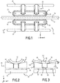
- Figure 1 shows a pipe tensioner 10 according to a first embodiment of the invention.
- the pipe tensioner 10 is particularly designed for the deployment of a pipe 12.
- the pipe tensioner 10 is installed on a pipelaying vessel (not shown).
- the pipe tensioner 10 comprises a fixed structure 14 and a plurality of track devices 16.
- the fixed structure 14, intended to be assembled to a deck of said pipelaying vessel, extends along a longitudinal axis 18.
- the longitudinal axis 18 may be horizontal, vertical or tilted.
- an orthonormal basis (X, Y, Z) is considered, the longitudinal axis 18 being parallel to direction X.
- the fixed structure 14 comprises a plurality of columns 20, parallel to and disposed around the longitudinal axis 18. Each of the track devices 16 is supported by a column 20.
- the fixed structure 14 comprises at least two, and preferably four or more track devices 16, regularly disposed around the longitudinal axis 18. On the pipe tensioner 10 of figure 1 , two track devices 16 are represented.
- Each of the track devices 16 comprises a track 22 and a radial translation apparatus 24.
- the track 22 substantially extends parallel to the longitudinal axis 18.
- the track 22 comprises a closed loop 26, such as a chain, rotatably movable around an elongated frame 28.
- An external face of the closed loop 26 bears a plurality of tensioner pad assemblies 30.
- the radial translation apparatus 24 of each track device 16 is connected to the frame 28 of the track 22, and to the supporting column 20.
- the radial translation apparatus 24 comprises pistons extending along a radial axis, said axis connecting the supporting column 20 and the longitudinal axis 18.
- the track devices 16 are able to exert a radial pressure on the pipe 12, maintaining said pipe coaxial to the longitudinal axis 18, or to release said pipe 12 by retreating near the supporting columns 20.
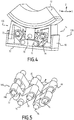
- Figures 2 and 3 represent a tensioner pad assembly 30 in two different configurations, in contact with pipes 12 and 112 of two different diameters.
- Figures 4 and 6 represent tensioner pad assemblies, respectively 130 and 230, according to a second and to a third embodiments of the invention.
- the tensioner pad assemblies 130 and 230 are able to replace the tensioner pad assemblies 30 of the pipe tensioner 10 of figure 1 .
- the tensioner pad assemblies 30, 130 and 230 are described simultaneously, the common features being designed by the same reference numbers.
- the tensioner pad assembly 30, 130, 230 comprises a mounting support 32, a tensioner pad 34 and an adjustment device 36, 136, 236.
- the mounting support 32 substantially has the shape of a plate parallel to the longitudinal axis 18. In the following description, said plate is considered to be disposed along (X, Y). One side of the mounting support 32 is able to be fixed to the closed loop 26.
- the tensioner pad 34 is disposed on the other side of the plate.
- the tensioner pad 34 comprises a central segment 40 and a first 42 and a second 44 lateral segments, each of said segments having a cylindrical shape extending parallel to X.
- Each of the cylinders has a quadrilateral base.
- the central segment 40 has a parallelepiped shape.
- the central segment 40 comprises a central surface 46, constituted by a face disposed along (X, Y) and opposed to the mounting support 32.
- the lateral segments 42, 44 are on each side of the central segment 40 according to direction Y.
- the first 42 and second 44 lateral segments respectively comprise a first 48 and a second 50 lateral surfaces.
- Each of the lateral surfaces 48, 50 is plane and inclined relative to the central surface 46 by an angle ⁇ .
- the angle ⁇ is comprised between 5° and 20°.
- the central surface 46 and lateral surfaces 48, 50 constitute a substantially concave contact surface 52 of the tensioner pad 34.
- the contact surface 52 is designed for being in contact with the pipe 12, 112 in the configuration of the pipe tensioner 10 shown on figure 1 .
- the adjustment device 36, 136, 236 allows each of the central segment 40 and lateral segments 42, 44 to be translatable relative to the mounting support 32 along a translation axis parallel to Z.
- the adjustment device 36 allows the central segment 40 and lateral segments 42, 44 to be translatable independently to one another. More precisely, the adjustment device 36 comprises three spring devices 60, 62, 64, connected to the mounting support 32 and respectively to the central segment 40, to the first lateral segment 42 and to the second lateral segment 44.
- the spring devices 60, 62, 64 may be hydraulic or pneumatic actuators.
- Each of the spring devices 60, 62, 64 has a resting position (not shown) and is able to translate parallel to Z towards the mounting support 32, under a pressure on the central surface 46 or lateral surface 48 or 50.
- the first and second configurations of the tensioner pad assembly 30, shown on figures 2 and 3 correspond to different positions of the central surface 46 and lateral surfaces 48, 50 relative to the mounting support 32.
- the adjustment device 136, 236 comprises three segment shafts 70, 72, 74, extending parallel to X and respectively fixed to the central segment 40 and to each of the lateral segments 42, 44.
- the adjustment device 136, 236 also comprises two support shafts 76 extending parallel to X and fixed to the mounting support 32.
- the adjustment device 136, 236 also comprises two elbow-shaped cranks 180, 280.
- Each crank comprises one or more sets of two arms 82, 84, fixed to each other.
- the two arms 82, 84 of a same crank 180, 280 form an angle ⁇ preferably comprised between 40° and 120°.
- cranks 180, 280 and shafts 70, 72, 74 and 76 are represented alone on figures 5 and 7 .
- a junction of the arms 82, 84 of each of the cranks 180, 280 forms a pivot with one of the support shafts 76.
- a free end of each of the arms 82, 24 of the cranks 180 comprises an oblong hole 186.
- Each of the oblong holes 186 is fitted around a segment shaft 70, 72, 74. More precisely, one of the oblong holes 186 of each crank 180 is fitted around the segment shaft 70 of the central segment and the other oblong hole of the same crank is fitted around the segment shaft 72, 74 of each lateral segment 42,44.
- an external surface 287 of a free end of each of the arms 82, 24 of the cranks 280 is in contact with a segment shaft 70, 72, 74. More precisely, one arm of each crank 280 is in contact with the segment shaft 70 of the central segment; the other arm of the same crank is in contact with the segment shaft 72, 74 of each lateral segment 42,44.
- the adjustment device 236 comprises three oblong rings 288 fixed to the mounting support 32.
- the oblong rings 288 have an oblong section perpendicular to X, said section being elongated along Z.
- Each of the oblong rings 288 is fitted around a segment shaft 70, 72, 74.
- the adjustment device 136, 236 also comprises guides 190, 290 able to guide a translation of the lateral segments 42, 44 relative to the mounting support 32, parallel to Z.
- the guides 190 comprise plates perpendicular to Y, fixed on lateral sides of the mounting support 32 and able to slide against external sides of the lateral segments 42, 44.
- the guides 290 comprise pins fixed to the mounting support 32 and able to slide in holes of the lateral segments 42, 44.
- the adjustment devices 136, 236, in particular the shafts and cranks, are confined in a closed compartment filled with a lubricant.
- An operating of the tensioner pad assembly 30 of figures 2 and 3 is as follows : as a first pipe 12, with an external surface 92 of a first diameter, is brought into contact with the contact surface 52, the spring devices 60, 62, 64 translate parallel to Z towards the mounting support 32, until each of the central surface 46 and lateral surfaces 48, 50 are in contact with a different generatrix of the external surface 92.
- the tensioner pad assembly 30 is in the first configuration shown on figure 2 .
- the spring devices 60, 62, 64 are calibrated so that a same pressure is exerted by each of the surfaces 46, 48, 50 on a different generatrix of the external surface 92.
- the spring devices 60, 62, 64 return to their resting position.
- the spring devices 60, 62, 64 translate parallel to Z until the external surface 192 of the pipe is in contact with each of the central surface 46 and lateral surfaces 48, 50.
- the tensioner pad assembly 30 is in the second configuration shown on figure 3 .
- the second diameter is bigger than the first diameter
- a space between the central surface 46 and the mounting support 32 is larger in the second configuration than in the first configuration.
- the lateral surfaces 48, 50 are closer to the mounting support 32 in the second configuration than in the first configuration. Therefore, the substantial concavity defined by the contact surface 52 has a bigger radius in the second configuration than in the first configuration.
- An operating of the tensioner pad assemblies 130, 230 of figures 4 and 6 is as follows : a pipe 12 is brought into contact with the contact surface 52 and exerts a pressure on said surface. Said pressure makes the cranks 180, 280 pivot around the support shafts 76.
- the oblong holes 186 or oblong rings 288, and the guides 190, 290, associate the rotating movements to a translating movement parallel to Z of the central surface 46 and lateral surfaces 48, 50.
- a stable equilibrium of the adjustment device 136, 236 is reached, with a same pressure is exerted by each of the surfaces 46, 48, 50 on a different generatrix of the external surface 92.
- the adjustment device 136, 236 reacts to the pressure of the pipe to reach a new equilibrium configuration.
- the contact surface 52 of the tensioner pad assemblies 30, 130, 230 is able to automatically adapt to the shape of the pipes 12, 112 within a large range of diameters.
Landscapes
- Engineering & Computer Science (AREA)
- Mechanical Engineering (AREA)
- Geology (AREA)
- General Engineering & Computer Science (AREA)
- Life Sciences & Earth Sciences (AREA)
- Mining & Mineral Resources (AREA)
- General Life Sciences & Earth Sciences (AREA)
- Fluid Mechanics (AREA)
- Environmental & Geological Engineering (AREA)
- Geochemistry & Mineralogy (AREA)
- Chemical & Material Sciences (AREA)
- Combustion & Propulsion (AREA)
- Ocean & Marine Engineering (AREA)
- Physics & Mathematics (AREA)
- Devices For Conveying Motion By Means Of Endless Flexible Members (AREA)
- Invalid Beds And Related Equipment (AREA)
Claims (12)
- Eine Spannpolsteranordnung (30, 130, 230) für eine Spanneinrichtung vom Gleiskettentyp,- einen Montageträger (32), und- ein Spannpolster (34), welches relativ zum Montageträger (32) bewegbar ist, wobei das Spannpolster eine Kontaktfläche (52) aufweist, welche sich parallel zu einer ersten Achse (X) erstreckt, wobei die Kontaktfläche dazu imstande ist, mit einer rohrförmigen Einrichtung (12, 112), welche sich parallel zur ersten Achse erstreckt, in Kontakt zu kommen,wobei das Spannpolster ein zentrales Segment (40) und ein erstes (42) und ein zweite (44) seitliches Segment aufweist, wobei das erste und das zweite seitliche Segment auf jeder Seite des zentralen Segments gemäß einer zweiten Achse (Y), welche senkrecht zur ersten Achse ist, vorliegen,
wobei das zentrale Segment und das erste und das zweite seitliche Segment jeweils zugeordnet eine zentrale Fläche (46) und eine erste (48) und eine zweite (50) seitliche Fläche aufweisen, wobei die zentrale Fläche und die erste und die zweite seitliche Fläche die Kontaktfläche des Spannpolsters bilden,
gekennzeichnet dadurch, dass
jede von der zentralen Fläche (46) und der ersten (48) und der zweiten (50) seitlichen Fläche planar ist, wobei die zentrale Fläche parallel zur ersten (X) und zur zweiten (Y) Achse ist, wobei die erste und die zweite seitliche Fläche bezüglich der zentralen Fläche geneigt ist,
wobei jedes von dem zentralen Segment und dem ersten und dem zweiten seitlichen Segment translatorisch (36, 136, 236) relativ zum Montageträger entlang einer Translationsachse (Z), welche senkrecht zur ersten und zur zweiten Achse ist, bewegbar sind, so dass die zentrale Fläche (46) relativ zur ersten (48) und zweiten (50) seitlichen Fläche entlang der Translationsachse (Z) translatorisch bewegbar ist. - Eine Spannpolsteranordnung gemäß Anspruch 1, wobei:- die zentrale Fläche (46) senkrecht zur Translationsachse (Z) ist, und- jede von der ersten (48) und der zweiten (50) seitlichen Fläche bezüglich der zentralen Fläche geneigt (α) ist, so dass ein zur ersten Achse senkrechter Querschnitt der Kontaktfläche (52) im Wesentlichen konkav ist.
- Eine Spannpolsteranordnung gemäß Anspruch 2, wobei ein Winkel (α) zwischen der zentralen Fläche und der ersten oder der zweiten seitlichen Fläche zwischen 5° und 20° liegt.
- Eine Spannpolsteranordnung gemäß einem der vorhergehenden Ansprüche, aufweisend eine Einstellvorrichtung (36, 136, 236), welche die Translationen des zentralen Segments (40) und des ersten und des zweiten seitlichen Segments (42, 44) bezüglich des Montageträgers (32) erlaubt, wobei die Translationen voneinander unabhängig sind.
- Eine Spannpolsteranordnung gemäß Anspruch 4, wobei die Einstellvorrichtung (36) eine Federeinrichtung (60, 62, 64), welche mit jedem von dem zentralen Segment (40) und dem ersten und dem zweiten seitlichen Segment (42, 44) im Zusammenhang steht, aufweist.
- Eine Spannpolsteranordnung gemäß einem der Ansprüche 1 bis 3, aufweisend eine Einstellvorrichtung (136, 236), welche die Translationen des zentralen Segments (40) und des ersten und des zweiten seitlichen Segments (42, 44) bezüglich des Montageträgers (32) erlaubt, wobei die Translationen voneinander abhängig sind.
- Eine Spannpolsteranordnung gemäß Anspruch 6, wobei die Einstellvorrichtung (136, 236) aufweist:- einen Segmentschaft (70, 72, 74), welcher an jedem von dem zentralen Segment (40) und dem ersten und dem zweiten seitlichen Segment (42, 44) befestigt ist,- zwei Stützschäfte (76), welcher an dem Montageträger (32) befestigt sind,
wobei jeder Segmentschaft und Stützschaft sich parallel zur ersten Achse erstreckt, und- zwei winkelförmige Kurbeln (180, 280), wobei jede Kurbel zwei aneinander befestigte Arme (82, 84) aufweist,
wobei eine Verbindungstelle der Arme (82, 84) jeder Kurbel ein Gelenk mit einem der Stützschäfte (76) bildet, wobei ein freies Ende eines jeden der Arme (82, 84) in Kontakt mit einem der Segmentschäfte (70, 72, 74) steht. - Eine Spannpolsteranordnung gemäß Anspruch 7, wobei ein freies Ende eines jeden der Arme (82, 84) ein Langloch (86) aufweist, wobei jedes der Langlöcher um einen der Segmentschäfte (70, 72, 74) herum angebracht ist.
- Eine Spannpolsteranordnung gemäß Anspruch 7, wobei:- eine äußere Fläche (287) eines freien Endes eines jeden der Arme (82, 84) in Kontakt mit einem Segmentschaft (70, 72, 74) steht, und
die Einstellvorrichtung (236) ebenfalls drei längliche Ringe (288) aufweist, welche an dem Montageträger (32) befestigt sind, wobei jeder der länglichen Ringe (288) um einen der Segmentschäfte (70, 72, 74) herum angebracht ist. - Eine Spannpolsteranordnung gemäß einem der Ansprüche 6 bis 9, wobei die Einstellvorrichtung (136, 236) ferner Führungen (190, 290) aufweist, welche dazu imstande sind, eine Translation des ersten und des zweiten seitlichen Segments (42, 44) relativ zum Montageträger (32) zu führen.
- Eine Gleiskette (22) für eine Rohrspanneinrichtung (10), wobei jede Gleiskette eine Mehrzahl von Spannpolsteranordnungen (30, 130, 230) gemäß einem der vorhergehenden Ansprüche aufweist.
- Eine Rohrspanneinrichtung, welche aufweist- eine feste Struktur (14), welche sich entlang einer Längsachse (18) erstreckt,- eine Mehrzahl von Gleisketten (22) gemäß Anspruch 11, wobei jede Gleiskette relativ zu der festen Struktur radial bewegbar ist, und- eine Radialtranslationsvorrichtung (24), welche mit jeder Gleiskette im Zusammenhang steht.
Priority Applications (3)
| Application Number | Priority Date | Filing Date | Title |
|---|---|---|---|
| EP16306384.5A EP3312486B1 (de) | 2016-10-21 | 2016-10-21 | Verstellbares spannvorrichtungspad für eine raupenspannvorrichtung und zugehörige spannvorrichtung |
| BR112019008150-0A BR112019008150B1 (pt) | 2016-10-21 | 2017-10-23 | Conjunto de almofada tensora, esteira e tensor de tubo |
| PCT/EP2017/077011 WO2018073453A1 (en) | 2016-10-21 | 2017-10-23 | Adjustable tensioner pad for a track-type tensioner and associated tensioner |
Applications Claiming Priority (1)
| Application Number | Priority Date | Filing Date | Title |
|---|---|---|---|
| EP16306384.5A EP3312486B1 (de) | 2016-10-21 | 2016-10-21 | Verstellbares spannvorrichtungspad für eine raupenspannvorrichtung und zugehörige spannvorrichtung |
Publications (2)
| Publication Number | Publication Date |
|---|---|
| EP3312486A1 EP3312486A1 (de) | 2018-04-25 |
| EP3312486B1 true EP3312486B1 (de) | 2021-05-05 |
Family
ID=57288325
Family Applications (1)
| Application Number | Title | Priority Date | Filing Date |
|---|---|---|---|
| EP16306384.5A Active EP3312486B1 (de) | 2016-10-21 | 2016-10-21 | Verstellbares spannvorrichtungspad für eine raupenspannvorrichtung und zugehörige spannvorrichtung |
Country Status (3)
| Country | Link |
|---|---|
| EP (1) | EP3312486B1 (de) |
| BR (1) | BR112019008150B1 (de) |
| WO (1) | WO2018073453A1 (de) |
Families Citing this family (3)
| Publication number | Priority date | Publication date | Assignee | Title |
|---|---|---|---|---|
| CN112141805B (zh) * | 2020-09-22 | 2021-12-10 | 合肥神马科技集团有限公司 | 一种利用轮胎牵引机的线缆牵引方法 |
| GB2613011B (en) | 2021-11-19 | 2024-06-26 | Subsea 7 Do Brasil Servicos Ltda | Hanging-off elongate elements during offshore operations |
| CN118515139B (zh) * | 2024-07-25 | 2024-09-17 | 常州泰尔格重工机械有限公司 | 一种电缆输送机及其工作方法 |
Family Cites Families (8)
| Publication number | Priority date | Publication date | Assignee | Title |
|---|---|---|---|---|
| FR2089215A5 (de) | 1970-04-09 | 1972-01-07 | Saipem Spa | |
| US3669329A (en) * | 1970-11-02 | 1972-06-13 | Western Gear Corp | Pipe tensioning unit |
| US3638288A (en) * | 1971-01-18 | 1972-02-01 | Youngstown Sheet And Tube Co | Gripper |
| NL194836C (nl) * | 1995-03-10 | 2003-04-03 | Allseas Group Sa | Inrichting voor het leggen van een pijpleiding op een onder water gelegen bodem. |
| ITMI20082120A1 (it) * | 2008-11-28 | 2010-05-29 | Saipem Spa | Gruppo di serraggio di una torre di varo di elementi allungati e continui in un corpo d'acqua e metodo di varo di un elemento allungato e continuo |
| CN102434720A (zh) | 2010-09-29 | 2012-05-02 | 中国海洋石油总公司 | 履带板组装置 |
| GB2513342B (en) | 2013-04-23 | 2016-04-13 | Mackinnon Marine Ltd | Tensioner pad assembly |
| NL2014813B1 (en) | 2015-05-18 | 2017-01-31 | Itrec Bv | Tensioner pad assembly. |
-
2016
- 2016-10-21 EP EP16306384.5A patent/EP3312486B1/de active Active
-
2017
- 2017-10-23 WO PCT/EP2017/077011 patent/WO2018073453A1/en not_active Ceased
- 2017-10-23 BR BR112019008150-0A patent/BR112019008150B1/pt active IP Right Grant
Also Published As
| Publication number | Publication date |
|---|---|
| WO2018073453A1 (en) | 2018-04-26 |
| BR112019008150A2 (pt) | 2019-07-02 |
| BR112019008150B1 (pt) | 2022-08-02 |
| EP3312486A1 (de) | 2018-04-25 |
Similar Documents
| Publication | Publication Date | Title |
|---|---|---|
| JP6236492B2 (ja) | 固定振れ止め | |
| US9593544B2 (en) | Clamp assembly | |
| EP3312486A1 (de) | Verstellbares spannvorrichtungspad für eine raupenspannvorrichtung und zugehörige spannvorrichtung | |
| EP2038572B1 (de) | Spannvorrichtung zum verlegen von pipelines im meer | |
| KR20130133906A (ko) | 관재 교정 장치 및 관재 교정 방법 | |
| AU2009321265A1 (en) | Clamp assembly for a laying tower and a method thereof | |
| EP3580484B1 (de) | Friktionsklemmvorrichtung zum verlegen von marinen rohrleitungen und verfahren zum verlegen einer rohrleitung | |
| US20160069478A1 (en) | Improved tensioner pad assembly | |
| KR101509219B1 (ko) | 레일 클램핑 장치 | |
| JP5562470B1 (ja) | 環状体の把持方法および装置 | |
| JP2014514160A5 (de) | ||
| JP5962684B2 (ja) | クランプ装置 | |
| KR101902901B1 (ko) | 원통형 미사일 바디 확관장치 | |
| EP3297941B1 (de) | Spannerklotzanordnung | |
| EP4100675B1 (de) | Spannkissen zum verlegen von unterwasserrohren und dergleichen | |
| EP4433732B1 (de) | Abhängung von länglichen elementen während offshore-operationen | |
| US5709117A (en) | Collet assembly for bending apparatus | |
| EP2273169A2 (de) | Spannungssteuerungsvorrichtung und Verfahren | |
| CN116329346B (zh) | 一种排水管道折弯加工设备 | |
| CN106002075B (zh) | J型铺管六自由度外对中装置 | |
| US20190211946A1 (en) | Deflector intended to guide a line and related guiding assembly | |
| WO2020069337A1 (en) | Pipe support system with multiple clamps | |
| KR20210142862A (ko) | 파이프라인 설치용 스팅거 | |
| CN112848794A (zh) | 用于夹紧车轮的轮辋的装置 | |
| NO335996B1 (no) | En føringssammenstilling innrettet til å føre et rørformet fleksibelt element |
Legal Events
| Date | Code | Title | Description |
|---|---|---|---|
| PUAI | Public reference made under article 153(3) epc to a published international application that has entered the european phase |
Free format text: ORIGINAL CODE: 0009012 |
|
| STAA | Information on the status of an ep patent application or granted ep patent |
Free format text: STATUS: THE APPLICATION HAS BEEN PUBLISHED |
|
| AK | Designated contracting states |
Kind code of ref document: A1 Designated state(s): AL AT BE BG CH CY CZ DE DK EE ES FI FR GB GR HR HU IE IS IT LI LT LU LV MC MK MT NL NO PL PT RO RS SE SI SK SM TR |
|
| AX | Request for extension of the european patent |
Extension state: BA ME |
|
| STAA | Information on the status of an ep patent application or granted ep patent |
Free format text: STATUS: REQUEST FOR EXAMINATION WAS MADE |
|
| 17P | Request for examination filed |
Effective date: 20181002 |
|
| RBV | Designated contracting states (corrected) |
Designated state(s): AL AT BE BG CH CY CZ DE DK EE ES FI FR GB GR HR HU IE IS IT LI LT LU LV MC MK MT NL NO PL PT RO RS SE SI SK SM TR |
|
| STAA | Information on the status of an ep patent application or granted ep patent |
Free format text: STATUS: EXAMINATION IS IN PROGRESS |
|
| 17Q | First examination report despatched |
Effective date: 20200406 |
|
| RAP1 | Party data changed (applicant data changed or rights of an application transferred) |
Owner name: TECHNIP N-POWER |
|
| GRAP | Despatch of communication of intention to grant a patent |
Free format text: ORIGINAL CODE: EPIDOSNIGR1 |
|
| STAA | Information on the status of an ep patent application or granted ep patent |
Free format text: STATUS: GRANT OF PATENT IS INTENDED |
|
| INTG | Intention to grant announced |
Effective date: 20201209 |
|
| TPAC | Observations filed by third parties |
Free format text: ORIGINAL CODE: EPIDOSNTIPA |
|
| GRAS | Grant fee paid |
Free format text: ORIGINAL CODE: EPIDOSNIGR3 |
|
| GRAA | (expected) grant |
Free format text: ORIGINAL CODE: 0009210 |
|
| STAA | Information on the status of an ep patent application or granted ep patent |
Free format text: STATUS: THE PATENT HAS BEEN GRANTED |
|
| AK | Designated contracting states |
Kind code of ref document: B1 Designated state(s): AL AT BE BG CH CY CZ DE DK EE ES FI FR GB GR HR HU IE IS IT LI LT LU LV MC MK MT NL NO PL PT RO RS SE SI SK SM TR |
|
| REG | Reference to a national code |
Ref country code: GB Ref legal event code: FG4D |
|
| REG | Reference to a national code |
Ref country code: CH Ref legal event code: EP |
|
| REG | Reference to a national code |
Ref country code: AT Ref legal event code: REF Ref document number: 1390223 Country of ref document: AT Kind code of ref document: T Effective date: 20210515 |
|
| REG | Reference to a national code |
Ref country code: IE Ref legal event code: FG4D |
|
| REG | Reference to a national code |
Ref country code: DE Ref legal event code: R096 Ref document number: 602016057292 Country of ref document: DE |
|
| REG | Reference to a national code |
Ref country code: NO Ref legal event code: T2 Effective date: 20210505 |
|
| REG | Reference to a national code |
Ref country code: NL Ref legal event code: FP |
|
| REG | Reference to a national code |
Ref country code: LT Ref legal event code: MG9D |
|
| REG | Reference to a national code |
Ref country code: AT Ref legal event code: MK05 Ref document number: 1390223 Country of ref document: AT Kind code of ref document: T Effective date: 20210505 |
|
| PG25 | Lapsed in a contracting state [announced via postgrant information from national office to epo] |
Ref country code: BG Free format text: LAPSE BECAUSE OF FAILURE TO SUBMIT A TRANSLATION OF THE DESCRIPTION OR TO PAY THE FEE WITHIN THE PRESCRIBED TIME-LIMIT Effective date: 20210805 Ref country code: AT Free format text: LAPSE BECAUSE OF FAILURE TO SUBMIT A TRANSLATION OF THE DESCRIPTION OR TO PAY THE FEE WITHIN THE PRESCRIBED TIME-LIMIT Effective date: 20210505 Ref country code: HR Free format text: LAPSE BECAUSE OF FAILURE TO SUBMIT A TRANSLATION OF THE DESCRIPTION OR TO PAY THE FEE WITHIN THE PRESCRIBED TIME-LIMIT Effective date: 20210505 Ref country code: FI Free format text: LAPSE BECAUSE OF FAILURE TO SUBMIT A TRANSLATION OF THE DESCRIPTION OR TO PAY THE FEE WITHIN THE PRESCRIBED TIME-LIMIT Effective date: 20210505 Ref country code: LT Free format text: LAPSE BECAUSE OF FAILURE TO SUBMIT A TRANSLATION OF THE DESCRIPTION OR TO PAY THE FEE WITHIN THE PRESCRIBED TIME-LIMIT Effective date: 20210505 |
|
| PG25 | Lapsed in a contracting state [announced via postgrant information from national office to epo] |
Ref country code: PL Free format text: LAPSE BECAUSE OF FAILURE TO SUBMIT A TRANSLATION OF THE DESCRIPTION OR TO PAY THE FEE WITHIN THE PRESCRIBED TIME-LIMIT Effective date: 20210505 Ref country code: PT Free format text: LAPSE BECAUSE OF FAILURE TO SUBMIT A TRANSLATION OF THE DESCRIPTION OR TO PAY THE FEE WITHIN THE PRESCRIBED TIME-LIMIT Effective date: 20210906 Ref country code: RS Free format text: LAPSE BECAUSE OF FAILURE TO SUBMIT A TRANSLATION OF THE DESCRIPTION OR TO PAY THE FEE WITHIN THE PRESCRIBED TIME-LIMIT Effective date: 20210505 Ref country code: SE Free format text: LAPSE BECAUSE OF FAILURE TO SUBMIT A TRANSLATION OF THE DESCRIPTION OR TO PAY THE FEE WITHIN THE PRESCRIBED TIME-LIMIT Effective date: 20210505 Ref country code: GR Free format text: LAPSE BECAUSE OF FAILURE TO SUBMIT A TRANSLATION OF THE DESCRIPTION OR TO PAY THE FEE WITHIN THE PRESCRIBED TIME-LIMIT Effective date: 20210806 Ref country code: IS Free format text: LAPSE BECAUSE OF FAILURE TO SUBMIT A TRANSLATION OF THE DESCRIPTION OR TO PAY THE FEE WITHIN THE PRESCRIBED TIME-LIMIT Effective date: 20210905 Ref country code: LV Free format text: LAPSE BECAUSE OF FAILURE TO SUBMIT A TRANSLATION OF THE DESCRIPTION OR TO PAY THE FEE WITHIN THE PRESCRIBED TIME-LIMIT Effective date: 20210505 |
|
| PG25 | Lapsed in a contracting state [announced via postgrant information from national office to epo] |
Ref country code: CZ Free format text: LAPSE BECAUSE OF FAILURE TO SUBMIT A TRANSLATION OF THE DESCRIPTION OR TO PAY THE FEE WITHIN THE PRESCRIBED TIME-LIMIT Effective date: 20210505 Ref country code: EE Free format text: LAPSE BECAUSE OF FAILURE TO SUBMIT A TRANSLATION OF THE DESCRIPTION OR TO PAY THE FEE WITHIN THE PRESCRIBED TIME-LIMIT Effective date: 20210505 Ref country code: DK Free format text: LAPSE BECAUSE OF FAILURE TO SUBMIT A TRANSLATION OF THE DESCRIPTION OR TO PAY THE FEE WITHIN THE PRESCRIBED TIME-LIMIT Effective date: 20210505 Ref country code: SM Free format text: LAPSE BECAUSE OF FAILURE TO SUBMIT A TRANSLATION OF THE DESCRIPTION OR TO PAY THE FEE WITHIN THE PRESCRIBED TIME-LIMIT Effective date: 20210505 Ref country code: SK Free format text: LAPSE BECAUSE OF FAILURE TO SUBMIT A TRANSLATION OF THE DESCRIPTION OR TO PAY THE FEE WITHIN THE PRESCRIBED TIME-LIMIT Effective date: 20210505 Ref country code: RO Free format text: LAPSE BECAUSE OF FAILURE TO SUBMIT A TRANSLATION OF THE DESCRIPTION OR TO PAY THE FEE WITHIN THE PRESCRIBED TIME-LIMIT Effective date: 20210505 Ref country code: ES Free format text: LAPSE BECAUSE OF FAILURE TO SUBMIT A TRANSLATION OF THE DESCRIPTION OR TO PAY THE FEE WITHIN THE PRESCRIBED TIME-LIMIT Effective date: 20210505 |
|
| REG | Reference to a national code |
Ref country code: DE Ref legal event code: R097 Ref document number: 602016057292 Country of ref document: DE |
|
| PLBE | No opposition filed within time limit |
Free format text: ORIGINAL CODE: 0009261 |
|
| STAA | Information on the status of an ep patent application or granted ep patent |
Free format text: STATUS: NO OPPOSITION FILED WITHIN TIME LIMIT |
|
| 26N | No opposition filed |
Effective date: 20220208 |
|
| REG | Reference to a national code |
Ref country code: DE Ref legal event code: R119 Ref document number: 602016057292 Country of ref document: DE |
|
| REG | Reference to a national code |
Ref country code: CH Ref legal event code: PL |
|
| PG25 | Lapsed in a contracting state [announced via postgrant information from national office to epo] |
Ref country code: IS Free format text: LAPSE BECAUSE OF FAILURE TO SUBMIT A TRANSLATION OF THE DESCRIPTION OR TO PAY THE FEE WITHIN THE PRESCRIBED TIME-LIMIT Effective date: 20210905 Ref country code: AL Free format text: LAPSE BECAUSE OF FAILURE TO SUBMIT A TRANSLATION OF THE DESCRIPTION OR TO PAY THE FEE WITHIN THE PRESCRIBED TIME-LIMIT Effective date: 20210505 |
|
| REG | Reference to a national code |
Ref country code: BE Ref legal event code: MM Effective date: 20211031 |
|
| PG25 | Lapsed in a contracting state [announced via postgrant information from national office to epo] |
Ref country code: MC Free format text: LAPSE BECAUSE OF FAILURE TO SUBMIT A TRANSLATION OF THE DESCRIPTION OR TO PAY THE FEE WITHIN THE PRESCRIBED TIME-LIMIT Effective date: 20210505 |
|
| PG25 | Lapsed in a contracting state [announced via postgrant information from national office to epo] |
Ref country code: LU Free format text: LAPSE BECAUSE OF NON-PAYMENT OF DUE FEES Effective date: 20211021 Ref country code: DE Free format text: LAPSE BECAUSE OF NON-PAYMENT OF DUE FEES Effective date: 20220503 Ref country code: BE Free format text: LAPSE BECAUSE OF NON-PAYMENT OF DUE FEES Effective date: 20211031 |
|
| PG25 | Lapsed in a contracting state [announced via postgrant information from national office to epo] |
Ref country code: LI Free format text: LAPSE BECAUSE OF NON-PAYMENT OF DUE FEES Effective date: 20211031 Ref country code: CH Free format text: LAPSE BECAUSE OF NON-PAYMENT OF DUE FEES Effective date: 20211031 |
|
| PG25 | Lapsed in a contracting state [announced via postgrant information from national office to epo] |
Ref country code: IE Free format text: LAPSE BECAUSE OF NON-PAYMENT OF DUE FEES Effective date: 20211021 |
|
| PG25 | Lapsed in a contracting state [announced via postgrant information from national office to epo] |
Ref country code: HU Free format text: LAPSE BECAUSE OF FAILURE TO SUBMIT A TRANSLATION OF THE DESCRIPTION OR TO PAY THE FEE WITHIN THE PRESCRIBED TIME-LIMIT; INVALID AB INITIO Effective date: 20161021 |
|
| P01 | Opt-out of the competence of the unified patent court (upc) registered |
Effective date: 20230516 |
|
| PG25 | Lapsed in a contracting state [announced via postgrant information from national office to epo] |
Ref country code: CY Free format text: LAPSE BECAUSE OF FAILURE TO SUBMIT A TRANSLATION OF THE DESCRIPTION OR TO PAY THE FEE WITHIN THE PRESCRIBED TIME-LIMIT Effective date: 20210505 |
|
| PG25 | Lapsed in a contracting state [announced via postgrant information from national office to epo] |
Ref country code: MK Free format text: LAPSE BECAUSE OF FAILURE TO SUBMIT A TRANSLATION OF THE DESCRIPTION OR TO PAY THE FEE WITHIN THE PRESCRIBED TIME-LIMIT Effective date: 20210505 |
|
| PG25 | Lapsed in a contracting state [announced via postgrant information from national office to epo] |
Ref country code: MT Free format text: LAPSE BECAUSE OF FAILURE TO SUBMIT A TRANSLATION OF THE DESCRIPTION OR TO PAY THE FEE WITHIN THE PRESCRIBED TIME-LIMIT Effective date: 20210505 |
|
| PGFP | Annual fee paid to national office [announced via postgrant information from national office to epo] |
Ref country code: NL Payment date: 20250926 Year of fee payment: 10 |
|
| PG25 | Lapsed in a contracting state [announced via postgrant information from national office to epo] |
Ref country code: TR Free format text: LAPSE BECAUSE OF FAILURE TO SUBMIT A TRANSLATION OF THE DESCRIPTION OR TO PAY THE FEE WITHIN THE PRESCRIBED TIME-LIMIT Effective date: 20210505 |
|
| PGFP | Annual fee paid to national office [announced via postgrant information from national office to epo] |
Ref country code: GB Payment date: 20251023 Year of fee payment: 10 |
|
| PGFP | Annual fee paid to national office [announced via postgrant information from national office to epo] |
Ref country code: NO Payment date: 20250930 Year of fee payment: 10 |
|
| PGFP | Annual fee paid to national office [announced via postgrant information from national office to epo] |
Ref country code: IT Payment date: 20251007 Year of fee payment: 10 |
|
| PGFP | Annual fee paid to national office [announced via postgrant information from national office to epo] |
Ref country code: FR Payment date: 20251027 Year of fee payment: 10 |