EP3312478A1 - Vehicle shift control device - Google Patents
Vehicle shift control device Download PDFInfo
- Publication number
- EP3312478A1 EP3312478A1 EP15896276.1A EP15896276A EP3312478A1 EP 3312478 A1 EP3312478 A1 EP 3312478A1 EP 15896276 A EP15896276 A EP 15896276A EP 3312478 A1 EP3312478 A1 EP 3312478A1
- Authority
- EP
- European Patent Office
- Prior art keywords
- gear
- oil pump
- transmission
- vehicle
- shaft
- Prior art date
- Legal status (The legal status is an assumption and is not a legal conclusion. Google has not performed a legal analysis and makes no representation as to the accuracy of the status listed.)
- Granted
Links
- 230000005540 biological transmission Effects 0.000 claims abstract description 214
- 230000007257 malfunction Effects 0.000 claims abstract description 66
- 238000005461 lubrication Methods 0.000 claims abstract description 50
- 230000007246 mechanism Effects 0.000 claims abstract description 20
- 238000002485 combustion reaction Methods 0.000 claims description 55
- 238000000034 method Methods 0.000 claims description 24
- 239000003921 oil Substances 0.000 abstract description 128
- 239000010687 lubricating oil Substances 0.000 abstract description 4
- 230000008569 process Effects 0.000 description 20
- 230000009471 action Effects 0.000 description 8
- 238000010248 power generation Methods 0.000 description 6
- 230000007935 neutral effect Effects 0.000 description 5
- 230000007704 transition Effects 0.000 description 5
- 230000007423 decrease Effects 0.000 description 3
- 230000000694 effects Effects 0.000 description 3
- 230000008929 regeneration Effects 0.000 description 3
- 238000011069 regeneration method Methods 0.000 description 3
- 230000001360 synchronised effect Effects 0.000 description 3
- 238000004891 communication Methods 0.000 description 2
- 239000000446 fuel Substances 0.000 description 2
- 239000007858 starting material Substances 0.000 description 2
- 238000007792 addition Methods 0.000 description 1
- 230000002457 bidirectional effect Effects 0.000 description 1
- 238000006243 chemical reaction Methods 0.000 description 1
- 230000008878 coupling Effects 0.000 description 1
- 238000010168 coupling process Methods 0.000 description 1
- 238000005859 coupling reaction Methods 0.000 description 1
- 238000005265 energy consumption Methods 0.000 description 1
- 239000012530 fluid Substances 0.000 description 1
- 239000003112 inhibitor Substances 0.000 description 1
- 238000002347 injection Methods 0.000 description 1
- 239000007924 injection Substances 0.000 description 1
- 238000012986 modification Methods 0.000 description 1
- 230000004048 modification Effects 0.000 description 1
- 238000002360 preparation method Methods 0.000 description 1
- 230000009467 reduction Effects 0.000 description 1
- 238000005549 size reduction Methods 0.000 description 1
Images


Classifications
-
- F—MECHANICAL ENGINEERING; LIGHTING; HEATING; WEAPONS; BLASTING
- F16—ENGINEERING ELEMENTS AND UNITS; GENERAL MEASURES FOR PRODUCING AND MAINTAINING EFFECTIVE FUNCTIONING OF MACHINES OR INSTALLATIONS; THERMAL INSULATION IN GENERAL
- F16H—GEARING
- F16H61/00—Control functions within control units of change-speed- or reversing-gearings for conveying rotary motion ; Control of exclusively fluid gearing, friction gearing, gearings with endless flexible members or other particular types of gearing
- F16H61/12—Detecting malfunction or potential malfunction, e.g. fail safe; Circumventing or fixing failures
-
- B—PERFORMING OPERATIONS; TRANSPORTING
- B60—VEHICLES IN GENERAL
- B60W—CONJOINT CONTROL OF VEHICLE SUB-UNITS OF DIFFERENT TYPE OR DIFFERENT FUNCTION; CONTROL SYSTEMS SPECIALLY ADAPTED FOR HYBRID VEHICLES; ROAD VEHICLE DRIVE CONTROL SYSTEMS FOR PURPOSES NOT RELATED TO THE CONTROL OF A PARTICULAR SUB-UNIT
- B60W10/00—Conjoint control of vehicle sub-units of different type or different function
- B60W10/30—Conjoint control of vehicle sub-units of different type or different function including control of auxiliary equipment, e.g. air-conditioning compressors or oil pumps
-
- B—PERFORMING OPERATIONS; TRANSPORTING
- B60—VEHICLES IN GENERAL
- B60W—CONJOINT CONTROL OF VEHICLE SUB-UNITS OF DIFFERENT TYPE OR DIFFERENT FUNCTION; CONTROL SYSTEMS SPECIALLY ADAPTED FOR HYBRID VEHICLES; ROAD VEHICLE DRIVE CONTROL SYSTEMS FOR PURPOSES NOT RELATED TO THE CONTROL OF A PARTICULAR SUB-UNIT
- B60W20/00—Control systems specially adapted for hybrid vehicles
- B60W20/50—Control strategies for responding to system failures, e.g. for fault diagnosis, failsafe operation or limp mode
-
- B—PERFORMING OPERATIONS; TRANSPORTING
- B60—VEHICLES IN GENERAL
- B60W—CONJOINT CONTROL OF VEHICLE SUB-UNITS OF DIFFERENT TYPE OR DIFFERENT FUNCTION; CONTROL SYSTEMS SPECIALLY ADAPTED FOR HYBRID VEHICLES; ROAD VEHICLE DRIVE CONTROL SYSTEMS FOR PURPOSES NOT RELATED TO THE CONTROL OF A PARTICULAR SUB-UNIT
- B60W30/00—Purposes of road vehicle drive control systems not related to the control of a particular sub-unit, e.g. of systems using conjoint control of vehicle sub-units, or advanced driver assistance systems for ensuring comfort, stability and safety or drive control systems for propelling or retarding the vehicle
- B60W30/18—Propelling the vehicle
- B60W30/184—Preventing damage resulting from overload or excessive wear of the driveline
- B60W30/1846—Preventing of breakage of drive line components, e.g. parts of the gearing
-
- F—MECHANICAL ENGINEERING; LIGHTING; HEATING; WEAPONS; BLASTING
- F01—MACHINES OR ENGINES IN GENERAL; ENGINE PLANTS IN GENERAL; STEAM ENGINES
- F01M—LUBRICATING OF MACHINES OR ENGINES IN GENERAL; LUBRICATING INTERNAL COMBUSTION ENGINES; CRANKCASE VENTILATING
- F01M1/00—Pressure lubrication
- F01M1/02—Pressure lubrication using lubricating pumps
-
- B—PERFORMING OPERATIONS; TRANSPORTING
- B60—VEHICLES IN GENERAL
- B60K—ARRANGEMENT OR MOUNTING OF PROPULSION UNITS OR OF TRANSMISSIONS IN VEHICLES; ARRANGEMENT OR MOUNTING OF PLURAL DIVERSE PRIME-MOVERS IN VEHICLES; AUXILIARY DRIVES FOR VEHICLES; INSTRUMENTATION OR DASHBOARDS FOR VEHICLES; ARRANGEMENTS IN CONNECTION WITH COOLING, AIR INTAKE, GAS EXHAUST OR FUEL SUPPLY OF PROPULSION UNITS IN VEHICLES
- B60K6/00—Arrangement or mounting of plural diverse prime-movers for mutual or common propulsion, e.g. hybrid propulsion systems comprising electric motors and internal combustion engines ; Control systems therefor, i.e. systems controlling two or more prime movers, or controlling one of these prime movers and any of the transmission, drive or drive units Informative references: mechanical gearings with secondary electric drive F16H3/72; arrangements for handling mechanical energy structurally associated with the dynamo-electric machine H02K7/00; machines comprising structurally interrelated motor and generator parts H02K51/00; dynamo-electric machines not otherwise provided for in H02K see H02K99/00
- B60K6/20—Arrangement or mounting of plural diverse prime-movers for mutual or common propulsion, e.g. hybrid propulsion systems comprising electric motors and internal combustion engines ; Control systems therefor, i.e. systems controlling two or more prime movers, or controlling one of these prime movers and any of the transmission, drive or drive units Informative references: mechanical gearings with secondary electric drive F16H3/72; arrangements for handling mechanical energy structurally associated with the dynamo-electric machine H02K7/00; machines comprising structurally interrelated motor and generator parts H02K51/00; dynamo-electric machines not otherwise provided for in H02K see H02K99/00 the prime-movers consisting of electric motors and internal combustion engines, e.g. HEVs
- B60K6/42—Arrangement or mounting of plural diverse prime-movers for mutual or common propulsion, e.g. hybrid propulsion systems comprising electric motors and internal combustion engines ; Control systems therefor, i.e. systems controlling two or more prime movers, or controlling one of these prime movers and any of the transmission, drive or drive units Informative references: mechanical gearings with secondary electric drive F16H3/72; arrangements for handling mechanical energy structurally associated with the dynamo-electric machine H02K7/00; machines comprising structurally interrelated motor and generator parts H02K51/00; dynamo-electric machines not otherwise provided for in H02K see H02K99/00 the prime-movers consisting of electric motors and internal combustion engines, e.g. HEVs characterised by the architecture of the hybrid electric vehicle
- B60K6/44—Series-parallel type
- B60K6/442—Series-parallel switching type
-
- B—PERFORMING OPERATIONS; TRANSPORTING
- B60—VEHICLES IN GENERAL
- B60K—ARRANGEMENT OR MOUNTING OF PROPULSION UNITS OR OF TRANSMISSIONS IN VEHICLES; ARRANGEMENT OR MOUNTING OF PLURAL DIVERSE PRIME-MOVERS IN VEHICLES; AUXILIARY DRIVES FOR VEHICLES; INSTRUMENTATION OR DASHBOARDS FOR VEHICLES; ARRANGEMENTS IN CONNECTION WITH COOLING, AIR INTAKE, GAS EXHAUST OR FUEL SUPPLY OF PROPULSION UNITS IN VEHICLES
- B60K6/00—Arrangement or mounting of plural diverse prime-movers for mutual or common propulsion, e.g. hybrid propulsion systems comprising electric motors and internal combustion engines ; Control systems therefor, i.e. systems controlling two or more prime movers, or controlling one of these prime movers and any of the transmission, drive or drive units Informative references: mechanical gearings with secondary electric drive F16H3/72; arrangements for handling mechanical energy structurally associated with the dynamo-electric machine H02K7/00; machines comprising structurally interrelated motor and generator parts H02K51/00; dynamo-electric machines not otherwise provided for in H02K see H02K99/00
- B60K6/20—Arrangement or mounting of plural diverse prime-movers for mutual or common propulsion, e.g. hybrid propulsion systems comprising electric motors and internal combustion engines ; Control systems therefor, i.e. systems controlling two or more prime movers, or controlling one of these prime movers and any of the transmission, drive or drive units Informative references: mechanical gearings with secondary electric drive F16H3/72; arrangements for handling mechanical energy structurally associated with the dynamo-electric machine H02K7/00; machines comprising structurally interrelated motor and generator parts H02K51/00; dynamo-electric machines not otherwise provided for in H02K see H02K99/00 the prime-movers consisting of electric motors and internal combustion engines, e.g. HEVs
- B60K6/50—Architecture of the driveline characterised by arrangement or kind of transmission units
- B60K6/54—Transmission for changing ratio
- B60K6/547—Transmission for changing ratio the transmission being a stepped gearing
-
- B—PERFORMING OPERATIONS; TRANSPORTING
- B60—VEHICLES IN GENERAL
- B60W—CONJOINT CONTROL OF VEHICLE SUB-UNITS OF DIFFERENT TYPE OR DIFFERENT FUNCTION; CONTROL SYSTEMS SPECIALLY ADAPTED FOR HYBRID VEHICLES; ROAD VEHICLE DRIVE CONTROL SYSTEMS FOR PURPOSES NOT RELATED TO THE CONTROL OF A PARTICULAR SUB-UNIT
- B60W10/00—Conjoint control of vehicle sub-units of different type or different function
- B60W10/04—Conjoint control of vehicle sub-units of different type or different function including control of propulsion units
- B60W10/06—Conjoint control of vehicle sub-units of different type or different function including control of propulsion units including control of combustion engines
-
- B—PERFORMING OPERATIONS; TRANSPORTING
- B60—VEHICLES IN GENERAL
- B60W—CONJOINT CONTROL OF VEHICLE SUB-UNITS OF DIFFERENT TYPE OR DIFFERENT FUNCTION; CONTROL SYSTEMS SPECIALLY ADAPTED FOR HYBRID VEHICLES; ROAD VEHICLE DRIVE CONTROL SYSTEMS FOR PURPOSES NOT RELATED TO THE CONTROL OF A PARTICULAR SUB-UNIT
- B60W10/00—Conjoint control of vehicle sub-units of different type or different function
- B60W10/04—Conjoint control of vehicle sub-units of different type or different function including control of propulsion units
- B60W10/08—Conjoint control of vehicle sub-units of different type or different function including control of propulsion units including control of electric propulsion units, e.g. motors or generators
-
- B—PERFORMING OPERATIONS; TRANSPORTING
- B60—VEHICLES IN GENERAL
- B60W—CONJOINT CONTROL OF VEHICLE SUB-UNITS OF DIFFERENT TYPE OR DIFFERENT FUNCTION; CONTROL SYSTEMS SPECIALLY ADAPTED FOR HYBRID VEHICLES; ROAD VEHICLE DRIVE CONTROL SYSTEMS FOR PURPOSES NOT RELATED TO THE CONTROL OF A PARTICULAR SUB-UNIT
- B60W10/00—Conjoint control of vehicle sub-units of different type or different function
- B60W10/10—Conjoint control of vehicle sub-units of different type or different function including control of change-speed gearings
- B60W10/11—Stepped gearings
-
- B—PERFORMING OPERATIONS; TRANSPORTING
- B60—VEHICLES IN GENERAL
- B60W—CONJOINT CONTROL OF VEHICLE SUB-UNITS OF DIFFERENT TYPE OR DIFFERENT FUNCTION; CONTROL SYSTEMS SPECIALLY ADAPTED FOR HYBRID VEHICLES; ROAD VEHICLE DRIVE CONTROL SYSTEMS FOR PURPOSES NOT RELATED TO THE CONTROL OF A PARTICULAR SUB-UNIT
- B60W10/00—Conjoint control of vehicle sub-units of different type or different function
- B60W10/24—Conjoint control of vehicle sub-units of different type or different function including control of energy storage means
- B60W10/26—Conjoint control of vehicle sub-units of different type or different function including control of energy storage means for electrical energy, e.g. batteries or capacitors
-
- B—PERFORMING OPERATIONS; TRANSPORTING
- B60—VEHICLES IN GENERAL
- B60W—CONJOINT CONTROL OF VEHICLE SUB-UNITS OF DIFFERENT TYPE OR DIFFERENT FUNCTION; CONTROL SYSTEMS SPECIALLY ADAPTED FOR HYBRID VEHICLES; ROAD VEHICLE DRIVE CONTROL SYSTEMS FOR PURPOSES NOT RELATED TO THE CONTROL OF A PARTICULAR SUB-UNIT
- B60W20/00—Control systems specially adapted for hybrid vehicles
- B60W20/40—Controlling the engagement or disengagement of prime movers, e.g. for transition between prime movers
-
- B—PERFORMING OPERATIONS; TRANSPORTING
- B60—VEHICLES IN GENERAL
- B60W—CONJOINT CONTROL OF VEHICLE SUB-UNITS OF DIFFERENT TYPE OR DIFFERENT FUNCTION; CONTROL SYSTEMS SPECIALLY ADAPTED FOR HYBRID VEHICLES; ROAD VEHICLE DRIVE CONTROL SYSTEMS FOR PURPOSES NOT RELATED TO THE CONTROL OF A PARTICULAR SUB-UNIT
- B60W30/00—Purposes of road vehicle drive control systems not related to the control of a particular sub-unit, e.g. of systems using conjoint control of vehicle sub-units, or advanced driver assistance systems for ensuring comfort, stability and safety or drive control systems for propelling or retarding the vehicle
- B60W30/18—Propelling the vehicle
- B60W30/19—Improvement of gear change, e.g. by synchronisation or smoothing gear shift
-
- F—MECHANICAL ENGINEERING; LIGHTING; HEATING; WEAPONS; BLASTING
- F16—ENGINEERING ELEMENTS AND UNITS; GENERAL MEASURES FOR PRODUCING AND MAINTAINING EFFECTIVE FUNCTIONING OF MACHINES OR INSTALLATIONS; THERMAL INSULATION IN GENERAL
- F16H—GEARING
- F16H59/00—Control inputs to control units of change-speed-, or reversing-gearings for conveying rotary motion
- F16H59/36—Inputs being a function of speed
- F16H2059/366—Engine or motor speed
-
- F—MECHANICAL ENGINEERING; LIGHTING; HEATING; WEAPONS; BLASTING
- F16—ENGINEERING ELEMENTS AND UNITS; GENERAL MEASURES FOR PRODUCING AND MAINTAINING EFFECTIVE FUNCTIONING OF MACHINES OR INSTALLATIONS; THERMAL INSULATION IN GENERAL
- F16H—GEARING
- F16H59/00—Control inputs to control units of change-speed-, or reversing-gearings for conveying rotary motion
- F16H59/68—Inputs being a function of gearing status
- F16H59/72—Inputs being a function of gearing status dependent on oil characteristics, e.g. temperature, viscosity
- F16H2059/725—Sensing or calculating temperature of friction devices, e.g. clutches to prevent overheating of friction linings
-
- F—MECHANICAL ENGINEERING; LIGHTING; HEATING; WEAPONS; BLASTING
- F16—ENGINEERING ELEMENTS AND UNITS; GENERAL MEASURES FOR PRODUCING AND MAINTAINING EFFECTIVE FUNCTIONING OF MACHINES OR INSTALLATIONS; THERMAL INSULATION IN GENERAL
- F16H—GEARING
- F16H61/00—Control functions within control units of change-speed- or reversing-gearings for conveying rotary motion ; Control of exclusively fluid gearing, friction gearing, gearings with endless flexible members or other particular types of gearing
- F16H61/04—Smoothing ratio shift
- F16H61/0403—Synchronisation before shifting
- F16H2061/0422—Synchronisation before shifting by an electric machine, e.g. by accelerating or braking the input shaft
-
- F—MECHANICAL ENGINEERING; LIGHTING; HEATING; WEAPONS; BLASTING
- F16—ENGINEERING ELEMENTS AND UNITS; GENERAL MEASURES FOR PRODUCING AND MAINTAINING EFFECTIVE FUNCTIONING OF MACHINES OR INSTALLATIONS; THERMAL INSULATION IN GENERAL
- F16H—GEARING
- F16H61/00—Control functions within control units of change-speed- or reversing-gearings for conveying rotary motion ; Control of exclusively fluid gearing, friction gearing, gearings with endless flexible members or other particular types of gearing
- F16H61/12—Detecting malfunction or potential malfunction, e.g. fail safe; Circumventing or fixing failures
- F16H2061/1232—Bringing the control into a predefined state, e.g. giving priority to particular actuators or gear ratios
-
- F—MECHANICAL ENGINEERING; LIGHTING; HEATING; WEAPONS; BLASTING
- F16—ENGINEERING ELEMENTS AND UNITS; GENERAL MEASURES FOR PRODUCING AND MAINTAINING EFFECTIVE FUNCTIONING OF MACHINES OR INSTALLATIONS; THERMAL INSULATION IN GENERAL
- F16H—GEARING
- F16H61/00—Control functions within control units of change-speed- or reversing-gearings for conveying rotary motion ; Control of exclusively fluid gearing, friction gearing, gearings with endless flexible members or other particular types of gearing
- F16H61/12—Detecting malfunction or potential malfunction, e.g. fail safe; Circumventing or fixing failures
- F16H2061/1256—Detecting malfunction or potential malfunction, e.g. fail safe; Circumventing or fixing failures characterised by the parts or units where malfunctioning was assumed or detected
- F16H2061/126—Detecting malfunction or potential malfunction, e.g. fail safe; Circumventing or fixing failures characterised by the parts or units where malfunctioning was assumed or detected the failing part is the controller
- F16H2061/1264—Hydraulic parts of the controller, e.g. a sticking valve or clogged channel
-
- F—MECHANICAL ENGINEERING; LIGHTING; HEATING; WEAPONS; BLASTING
- F16—ENGINEERING ELEMENTS AND UNITS; GENERAL MEASURES FOR PRODUCING AND MAINTAINING EFFECTIVE FUNCTIONING OF MACHINES OR INSTALLATIONS; THERMAL INSULATION IN GENERAL
- F16H—GEARING
- F16H2200/00—Transmissions for multiple ratios
- F16H2200/0021—Transmissions for multiple ratios specially adapted for electric vehicles
-
- F—MECHANICAL ENGINEERING; LIGHTING; HEATING; WEAPONS; BLASTING
- F16—ENGINEERING ELEMENTS AND UNITS; GENERAL MEASURES FOR PRODUCING AND MAINTAINING EFFECTIVE FUNCTIONING OF MACHINES OR INSTALLATIONS; THERMAL INSULATION IN GENERAL
- F16H—GEARING
- F16H2200/00—Transmissions for multiple ratios
- F16H2200/003—Transmissions for multiple ratios characterised by the number of forward speeds
- F16H2200/0052—Transmissions for multiple ratios characterised by the number of forward speeds the gear ratios comprising six forward speeds
-
- F—MECHANICAL ENGINEERING; LIGHTING; HEATING; WEAPONS; BLASTING
- F16—ENGINEERING ELEMENTS AND UNITS; GENERAL MEASURES FOR PRODUCING AND MAINTAINING EFFECTIVE FUNCTIONING OF MACHINES OR INSTALLATIONS; THERMAL INSULATION IN GENERAL
- F16H—GEARING
- F16H2200/00—Transmissions for multiple ratios
- F16H2200/20—Transmissions using gears with orbital motion
- F16H2200/203—Transmissions using gears with orbital motion characterised by the engaging friction means not of the freewheel type, e.g. friction clutches or brakes
- F16H2200/2038—Transmissions using gears with orbital motion characterised by the engaging friction means not of the freewheel type, e.g. friction clutches or brakes with three engaging means
-
- F—MECHANICAL ENGINEERING; LIGHTING; HEATING; WEAPONS; BLASTING
- F16—ENGINEERING ELEMENTS AND UNITS; GENERAL MEASURES FOR PRODUCING AND MAINTAINING EFFECTIVE FUNCTIONING OF MACHINES OR INSTALLATIONS; THERMAL INSULATION IN GENERAL
- F16H—GEARING
- F16H2200/00—Transmissions for multiple ratios
- F16H2200/20—Transmissions using gears with orbital motion
- F16H2200/203—Transmissions using gears with orbital motion characterised by the engaging friction means not of the freewheel type, e.g. friction clutches or brakes
- F16H2200/2064—Transmissions using gears with orbital motion characterised by the engaging friction means not of the freewheel type, e.g. friction clutches or brakes using at least one positive clutch, e.g. dog clutch
-
- F—MECHANICAL ENGINEERING; LIGHTING; HEATING; WEAPONS; BLASTING
- F16—ENGINEERING ELEMENTS AND UNITS; GENERAL MEASURES FOR PRODUCING AND MAINTAINING EFFECTIVE FUNCTIONING OF MACHINES OR INSTALLATIONS; THERMAL INSULATION IN GENERAL
- F16H—GEARING
- F16H57/00—General details of gearing
- F16H57/04—Features relating to lubrication or cooling or heating
- F16H57/042—Guidance of lubricant
- F16H57/043—Guidance of lubricant within rotary parts, e.g. axial channels or radial openings in shafts
-
- F—MECHANICAL ENGINEERING; LIGHTING; HEATING; WEAPONS; BLASTING
- F16—ENGINEERING ELEMENTS AND UNITS; GENERAL MEASURES FOR PRODUCING AND MAINTAINING EFFECTIVE FUNCTIONING OF MACHINES OR INSTALLATIONS; THERMAL INSULATION IN GENERAL
- F16H—GEARING
- F16H57/00—General details of gearing
- F16H57/04—Features relating to lubrication or cooling or heating
- F16H57/045—Lubricant storage reservoirs, e.g. reservoirs in addition to a gear sump for collecting lubricant in the upper part of a gear case
-
- F—MECHANICAL ENGINEERING; LIGHTING; HEATING; WEAPONS; BLASTING
- F16—ENGINEERING ELEMENTS AND UNITS; GENERAL MEASURES FOR PRODUCING AND MAINTAINING EFFECTIVE FUNCTIONING OF MACHINES OR INSTALLATIONS; THERMAL INSULATION IN GENERAL
- F16H—GEARING
- F16H57/00—General details of gearing
- F16H57/04—Features relating to lubrication or cooling or heating
- F16H57/0457—Splash lubrication
-
- F—MECHANICAL ENGINEERING; LIGHTING; HEATING; WEAPONS; BLASTING
- F16—ENGINEERING ELEMENTS AND UNITS; GENERAL MEASURES FOR PRODUCING AND MAINTAINING EFFECTIVE FUNCTIONING OF MACHINES OR INSTALLATIONS; THERMAL INSULATION IN GENERAL
- F16H—GEARING
- F16H57/00—General details of gearing
- F16H57/04—Features relating to lubrication or cooling or heating
- F16H57/0467—Elements of gearings to be lubricated, cooled or heated
- F16H57/0469—Bearings or seals
- F16H57/0471—Bearing
-
- F—MECHANICAL ENGINEERING; LIGHTING; HEATING; WEAPONS; BLASTING
- F16—ENGINEERING ELEMENTS AND UNITS; GENERAL MEASURES FOR PRODUCING AND MAINTAINING EFFECTIVE FUNCTIONING OF MACHINES OR INSTALLATIONS; THERMAL INSULATION IN GENERAL
- F16H—GEARING
- F16H57/00—General details of gearing
- F16H57/04—Features relating to lubrication or cooling or heating
- F16H57/048—Type of gearings to be lubricated, cooled or heated
- F16H57/0493—Gearings with spur or bevel gears
- F16H57/0494—Gearings with spur or bevel gears with variable gear ratio or for reversing rotary motion
-
- F—MECHANICAL ENGINEERING; LIGHTING; HEATING; WEAPONS; BLASTING
- F16—ENGINEERING ELEMENTS AND UNITS; GENERAL MEASURES FOR PRODUCING AND MAINTAINING EFFECTIVE FUNCTIONING OF MACHINES OR INSTALLATIONS; THERMAL INSULATION IN GENERAL
- F16H—GEARING
- F16H59/00—Control inputs to control units of change-speed-, or reversing-gearings for conveying rotary motion
- F16H59/36—Inputs being a function of speed
- F16H59/38—Inputs being a function of speed of gearing elements
- F16H59/40—Output shaft speed
-
- F—MECHANICAL ENGINEERING; LIGHTING; HEATING; WEAPONS; BLASTING
- F16—ENGINEERING ELEMENTS AND UNITS; GENERAL MEASURES FOR PRODUCING AND MAINTAINING EFFECTIVE FUNCTIONING OF MACHINES OR INSTALLATIONS; THERMAL INSULATION IN GENERAL
- F16H—GEARING
- F16H59/00—Control inputs to control units of change-speed-, or reversing-gearings for conveying rotary motion
- F16H59/68—Inputs being a function of gearing status
- F16H59/72—Inputs being a function of gearing status dependent on oil characteristics, e.g. temperature, viscosity
-
- Y—GENERAL TAGGING OF NEW TECHNOLOGICAL DEVELOPMENTS; GENERAL TAGGING OF CROSS-SECTIONAL TECHNOLOGIES SPANNING OVER SEVERAL SECTIONS OF THE IPC; TECHNICAL SUBJECTS COVERED BY FORMER USPC CROSS-REFERENCE ART COLLECTIONS [XRACs] AND DIGESTS
- Y02—TECHNOLOGIES OR APPLICATIONS FOR MITIGATION OR ADAPTATION AGAINST CLIMATE CHANGE
- Y02T—CLIMATE CHANGE MITIGATION TECHNOLOGIES RELATED TO TRANSPORTATION
- Y02T10/00—Road transport of goods or passengers
- Y02T10/60—Other road transportation technologies with climate change mitigation effect
- Y02T10/62—Hybrid vehicles
Definitions
- the present invention relates to a vehicle transmission control device comprising an oil pump that supplies lubrication oil to a gear-shifting mechanism.
- Patent Document 1 An example of a vehicle transmission control device comprising an oil pump that supplies lubrication oil to a transmission mechanism is a technique disclosed in Patent Document 1.
- an electric oil pump that supplies lubrication oil to lubricated parts of a gear type shifting mechanism is provided, and the discharge amount of the electric oil pump is controlled in accordance with the operating state of the vehicle.
- the technique disclosed in Patent Document 1 improves the design flexibility of the transmission, and prevents seizing of lubricated parts and damage thereto.
- Patent Document 1 Japanese Laid Open Patent Application No. Hei 4(1992)-285358
- an object of the present invention is to provide a vehicle transmission control device in a vehicle provided with an oil pump for supplying lubricating oil to a gear-shifting mechanism, which is configured to be able to prevent seizing of lubricated parts and damage thereto, if a malfunction occurs in the oil pump.
- a vehicle of the present invention comprises a transmission having a gear-shifting mechanism that obtains a plurality of gear shift stages by selecting a plurality of power transmission paths, and an oil pump that supplies lubrication oil to lubricated parts of the gear-shifting mechanism.
- the transmission control device of the present invention is provided with a transmission controller for selecting a plurality of power transmission paths.
- the transmission controller selects a path having a small load on the lubricated parts from among a plurality of power transmission paths upon detecting a malfunction has occurred in the oil pump.
- a power transmission path having a small load on the lubricated parts is selected upon detecting a malfunction has occurred in the oil pump.
- the transmission control device of the embodiment is applied to a hybrid vehicle (one example of an electrically driven vehicle), comprising, as drive system components, one engine, two motor/generators, and a multistage gear transmission having three engagement clutches.
- a hybrid vehicle one example of an electrically driven vehicle
- the "overall system configuration,” the “configuration of the transmission,” the “configuration of the gear shift patterns,” and the “configuration of the shift control process” will be separately described below, regarding the configuration of the transmission control device for a hybrid vehicle in the embodiment.
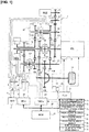
- Figure 1 illustrates a drive system and a control system of a vehicle (hybrid vehicle) to which is applied the transmission control device of the embodiment.
- vehicle hybrid vehicle
- the overall system configuration will be described below, based on Figure 1 .
- the drive system of the hybrid vehicle comprises an internal combustion engine ICE, a first motor/generator MG1, a second motor/generator MG2, and a multistage gear transmission 1 having three engagement clutches C1, C2, //C3//, as illustrated in Figure 1 .
- ICE is an acronym for "Internal Combustion Engine.”
- the internal combustion engine ICE is, for example, a gasoline engine or a diesel engine that is disposed in a front room of a vehicle such that the crankshaft direction is in the vehicle width direction.
- This internal combustion engine ICE is connected to a transmission case 10 of the multistage gear transmission 1, and the output shaft of the internal combustion engine is connected to a first shaft 11 (first gear shaft) of the multistage gear transmission 1.
- the internal combustion engine ICE basically carries out an MG2 start, where the second motor/generator MG2 is used as a starter motor. However, a starter motor 2 is left in preparation for when an MG2 start using a high-power battery 3 cannot be ensured, such as during extreme cold.
- Both the first motor/generator MG1 and the second motor/generator MG2 are permanent magnet type synchronous motors utilizing a three-phase alternating current, having the high-power battery 3 as a common power source.
- the stator of the first motor/generator MG1 is fixed to a case of the first motor/generator MG1, and the case is fixed to the transmission case 10 of the multistage gear transmission 1.
- a first motor shaft integrated to a rotor of the first motor/generator MG1 is connected to a second shaft 12 of the multistage gear transmission 1.
- the stator of the second motor/generator MG2 is fixed to a case of the second motor/generator MG2, and the case is fixed to the transmission case 10 of the multistage gear transmission 1.
- a second motor shaft integrated to a rotor of the second motor/generator MG2 is connected to a sixth shaft 16 of the multistage gear transmission 1.
- a first inverter 4 which converts direct current to three-phase alternating current during powering and converts three-phase alternating current to direct current during regeneration, is connected to a stator coil of the first motor/generator MG1, via a first AC harness 5.
- the high-power battery 3, the first inverter 4, and the second inverter 6 are connected by a DC harness 8, via a junction box 9.
- the multistage gear transmission 1 is a normally meshing transmission comprising a plurality of gear pairs having different transmission ratios, and comprises six gear shafts 11-16 provided with gears and disposed parallel to each other inside the transmission case 10, and three engagement clutches C1, C2, C3 for selecting a gear pair.
- a first shaft 11, a second shaft 12, a third shaft 13, a fourth shaft 14, a fifth shaft 15, and a sixth shaft 16 are provided as gear shafts.
- a first engagement clutch C1, a second engagement clutch C2, and a third engagement clutch C3 are provided as engagement clutches.
- the transmission case 10 is provided with an electric oil pump (oil pump) 20 that supplies lubrication oil to the meshing portions of the gears and the bearing portions (bearing) inside the case.
- the first shaft 11 is a shaft to which the internal combustion engine ICE is connected, and a first gear 101, a second gear 102 (first power transmission gear), and a third gear 103 are disposed on the first shaft 11, in order from the right side in Figure 1 .
- the first gear 101 is integrally provided (including integral fixing) to the first shaft 11.
- the second gear 102 and the third gear 103 are idling gears, in which a boss portion that protrudes in the axial direction is inserted onto the outer perimeter of the first shaft 11, and are provided so as to be drivably connectable to the first shaft 11 via the second engagement clutch C2.
- the second shaft 12 (second gear shaft) is a shaft to which the first motor/generator MG1 is connected, and is a hollow cylindrical shaft coaxially disposed with the axis aligned with the outer side position of the first shaft 11, and a fourth gear 104 (fourth power transmission gear) and a fifth gear 105 (fourth power transmission gear) are disposed on the second shaft 12, in order from the right side in Figure 1 .
- the fourth gear 104 and the fifth gear 105 are integrally provided (including integral fixing) to the second shaft 12.
- the third shaft 13 is a shaft disposed on the output side of the multistage gear transmission 1, and a sixth gear 106 (third power transmission gear), a seventh gear 107, an eighth gear 108, a ninth gear 109 (sixth power transmission gear), and a tenth gear 110 (sixth power transmission gear) are disposed on the third shaft 13, in order from the right side in Figure 1 .
- the sixth gear 106, the seventh gear 107, and the eighth gear 108 are integrally provided (including integral fixing) to the third shaft 13.
- the ninth gear 109 and the tenth gear 110 are idling gears, in which boss portions protruding in the axial direction are inserted onto the outer perimeter of the third shaft 13, and are provided so as to be drivably connectable to the third shaft 13 via the third engagement clutch C3.
- the sixth gear 106 meshes with the second gear 102 of the first shaft 11
- the seventh gear 107 meshes with a sixteenth gear 116 of a differential gear 17
- the eighth gear 108 meshes with the third gear 103 of the first shaft 11.
- the ninth gear 109 meshes with the fourth gear 104 of the second shaft 12, and the tenth gear 110 meshes with the fifth gear 105 of the second shaft 12.
- the fourth shaft 14 has both ends supported on the transmission case 10, with an eleventh gear 111, a twelfth gear 112 (second power transmission gear), and a thirteenth gear 113 (fifth power transmission gear) are disposed on the fourth shaft 14, in order from the right side in Figure 1 .
- the eleventh gear 111 is integrally provided (including integral fixing) to the fourth shaft 14.
- the twelfth gear 112 and the thirteenth gear 113 are idling gears, in which a boss portion protruding in the axial direction is inserted onto the outer perimeter of the fourth shaft 14, and are provided so as to be drivably connectable to the fourth shaft 14 via the first engagement clutch C1.
- the eleventh gear 111 meshes with the first gear 101 of the first shaft 11
- the twelfth gear 112 meshes with a second gear 102 of the first shaft 11
- the thirteenth gear 113 meshes with the fourth gear 104 of the second shaft 12.
- the fifth shaft 15 has both ends are supported on the transmission case 10, and a fourteenth gear 114 that meshes with the eleventh gear 111 of the fourth shaft 14 is integrally provided thereto (including integral fixing).
- the sixth shaft 16 is connected to the second motor/generator MG2, and a fifteenth gear 115 that meshes with the fourteenth gear 114 of the fifth shaft 15 is integrally provided thereto (including integral fixing).
- the second motor/generator MG2 and the internal combustion engine ICE are mechanically connected to each other by a gear train configured from the fifteenth gear 115, the fourteenth gear 114, the eleventh gear 111, and the first gear 101, which mesh with each other.
- This gear train serves as a reduction gear train that decelerates the MG2 rotational speed at the time of an MG2 start of the internal combustion engine ICE by the second motor/generator MG2, and serves as a speed increasing gear train that accelerates the engine rotational speed at the time of MG2 power generation for generating the second motor/generator MG2, by the driving of the internal combustion engine ICE.
- the first engagement clutch C1 is a dog clutch interposed between the twelfth gear 112 and the thirteenth gear 113 of the fourth shaft 14, and that is engaged by an engagement movement in a rotation synchronization state by not having a synchronization mechanism.
- the first engagement clutch C1 When the first engagement clutch C1 is in a left engagement position (Left), the fourth shaft 14 and the thirteenth gear 113 are drivingly connected.
- the first engagement clutch C1 is in a neutral position (N), the fourth shaft 14 and the twelfth gear 112 are released, and the fourth shaft 14 and the thirteenth gear 113 are released.
- the first engagement clutch C1 is in a right engagement position (Right), the fourth shaft 14 and the twelfth gear 112 are drivingly connected.
- the second engagement clutch C2 is a dog clutch interposed between the second gear 102 and the third gear 103 of the first shaft 11, and that is engaged by an engagement movement in a rotation synchronization state by not having a synchronization mechanism.
- the second engagement clutch C2 When the second engagement clutch C2 is in a left engagement position (Left), the first shaft 11 and the third gear 103 are drivingly connected.
- the second engagement clutch C2 When the second engagement clutch C2 is in a neutral position (N), the first shaft 11 and the second gear 102 are released, and the first shaft 11 and the third gear 103 are released.
- the second engagement clutch C2 is in a right engagement position (Right), the first shaft 11 and the second gear 102 are drivingly connected.
- the third engagement clutch C3 is a dog clutch interposed between the ninth gear 109 and the tenth gear 110 of the third shaft 13, and that is engaged by an engagement movement in a rotation synchronization state by not having a synchronization mechanism.
- the third engagement clutch C3 When the third engagement clutch C3 is in a left engagement position (Left), the third shaft 13 and the tenth gear 110 are drivingly connected.
- the third engagement clutch C3 When the third engagement clutch C3 is in a neutral position (N), the third shaft 13 and the ninth gear 109 are released, and the third shaft 13 and the tenth gear 110 are released.
- the third engagement clutch C3 is in a right engagement position (Right), the third shaft 13 and the ninth gear 109 are drivingly connected.
- a sixteenth gear 116 that meshes with the seventh gear 107 integrally provided (including integral fixing) to the third shaft 13 of the multistage gear transmission 1 is connected to left and right drive wheels 19 via the differential gear 17 and left and right drive shafts 18.
- the control system of the hybrid vehicle comprises a hybrid control module 21, a motor control unit 22, a transmission control unit 23, and an engine control unit 24, as illustrated in Figure 1 .
- the hybrid control module 21 (acronym: “HCM”) is an integrated control means to appropriately manage the energy consumption of the entire vehicle.
- This hybrid control module 21 is connected to the other control units (motor control unit 22, transmission control unit 23, engine control unit 24, etc.) so as to be capable of bidirectional information exchange by a CAN communication line 25.
- the "CAN” in CAN communication line 25 is an acronym for "Controller Area Network.”
- the motor control unit 22 (acronym: "MCU”) carries out powering control, regeneration control, and the like, of the first motor/generator MG1 and the second motor/generator MG2, by control commands to the first inverter 4 and the second inverter 6.
- the control modes for the first motor/generator MG1 and the second motor/generator MG2 are "torque control” and "rotational speed FB control.”
- torque control a control is carried out in which the actual motor torque is caused to follow a target motor torque, when a target motor torque to be shared with respect to a target drive force is determined.
- rotational speed FB control a control is carried out in which a target motor rotational speed, with which the input/output rotational speeds of the clutch are synchronized, is determined, and an FB torque is output so as to converge the actual motor rotational speed to the target motor rotational speed, when there is a gear shift request to mesh and engage any one of the engagement clutches C1, C2, C3 during traveling.
- the transmission control unit 23 (acronym "TMCU") carries out a shift control for switching the gear shift pattern (power transmission path) of the multistage gear transmission 1, by outputting a current command to electric actuators 31, 32, 33 (not shown) of the first, second, and third engagement clutches C1, C2, C3, based on predetermined input information.
- the engagement clutches C1, C2, C3 are selectively mesh engaged/released, and a gear pair involved in power transmission is selected from the plurality of pairs of gear pairs.
- a rotational speed FB control rotation synchronization control of the first motor/generator MG1 or the second motor/generator MG2 is used in combination.
- the transmission control unit 23 inputs sensor signals and switch signals from a vehicle speed sensor 71, an accelerator position opening amount sensor 72, a transmission output shaft rotational speed sensor 73, an engine rotational speed sensor 74, an MG1 rotational speed sensor 75, an MG2 rotational speed sensor 76, an inhibitor switch 77, an oil pump rotational speed sensor 78, and the like.
- the transmission output shaft rotational speed sensor 73 is provided to the shaft end portion of the third shaft 13 and detects the shaft rotational speed of the third shaft 13.
- the transmission control unit 23 determines whether or not a malfunction has occurred in the electric oil pump 20, based on a sensor signal of the oil pump rotational speed sensor 78.
- the determination of whether or not a malfunction has occurred in the electric oil pump 20 is not limited to an oil pump rotational speed sensor 78, and, for example, may be determined by providing a hydraulic pressure sensor to the electric oil pump 20, by providing a temperature sensor to the lubricated parts described later, or by a combination thereof. That is, if a malfunction occurs in the electric oil pump 20, the discharge pressure of the electric oil pump 20 decreases while the temperature of the lubricated parts increases; it is thereby also possible to determine a malfunction in the electric oil pump 20 based on these changes.
- the engine control unit 24 (acronym "ECU”) carries out start control of the internal combustion engine ICE, stop control of the internal combustion engine ICE, fuel cut control, and the like, by outputting a control command to the motor control unit 22, a spark plug, a fuel injection actuator, or the like, based on predetermined input information.
- the multistage gear transmission 1 is characterized in that efficiency is obtained by reducing drag by employing, as shifting elements, engagement clutches C1, C2, C3 (dog clutch) that are meshingly engaged. Then, when there is a gear shift request to mesh and engage any one of the engagement clutches C1, C2, C3, the differential rotational speeds of the input/output of the clutch are synchronized by the first motor/generator MG1 (when the engagement clutch C3 is engaged) or the second motor/generator MG2 (when the engagement clutches C1, C2 are engaged), and an engagement movement is started once the rotational speed falls within a synchronization determination rotational speed range, to realize the gear shift.
- engagement clutches C1, C2, C3 dog clutch
- Figure 2 is a cross-sectional view of the multistage gear transmission 1 of the embodiment. The configuration of the transmission 1 of the embodiment will be described below, based on Figure 2 .
- the second gear 102 and the third gear 103 are disposed on the outer perimeter side of the first shaft 11, which is connected to the output shaft of the internal combustion engine ICE, via a second bearing portion 202 and a third bearing portion 203, respectively, as illustrated in Figure 2 .
- the first shaft 11 is supported to the transmission case 10 by the eleventh bearing portion 211, and is supported inside the second shaft 12, which is a cylindrical shaft, by the fourth bearing portion 204 and the fifth bearing portion 205.
- the fourth bearing portion 204 is interposed between the first shaft 11 and the fourth gear 104, which is integrally provided with the second shaft 12.
- the fifth bearing portion 205 is interposed between the first shaft 11 and the fifth gear 105, which is integrally provided with the second shaft 12.
- the second shaft 12 is supported to the transmission case 10 by the twelfth bearing portion 212.
- the fourth shaft 14 is supported to the transmission case 10 by the fourteenth bearing portion 214.
- the fifth shaft 15 is supported to the transmission case 10 by the fifteenth bearing portion 215.
- the sixth shaft 16 is supported to the transmission case 10 by the sixteenth bearing portion 216.
- the electric oil pump 20 supplies lubrication oil to the bearing portions and gears described above. Specifically, the discharge passage (not shown) of the electric oil pump 20 is connected to a lubrication oil passage 11a provided inside the first shaft 11, and the lubrication oil that is discharged from the electric oil pump 20 is supplied to each bearing portion (202, 203, 204, 205, and the like) and each gear (101-105, and the like) via the lubrication oil passage 11a of the first shaft 11.
- the multistage gear transmission 1 comprises a plurality of bearing portions and gears in addition to the above, as illustrated in Figure 2 , but detailed descriptions of the other configurations are omitted.
- rotating elements to which lubrication oil is supplied such as the plurality of bearing portions (22nd and third bearing portions 202, 203, etc.) and the plurality of gears (first and second gears 101, 102, etc.) described above, are collectively referred to as "lubricated parts.”
- the multistage gear transmission 1 of the first embodiment is characterized in that size reduction is obtained by reducing the power transmission loss by not having a differential rotation absorbing element, such as a fluid coupling, and by reducing ICE gear shift stages (gear shift stages of the internal combustion engine ICE) by providing motor assistance to the internal combustion engine ICE (EV gear shift stages: 1-2 speed, ICE gear shift stages: 1-4 speed).
- ICE gear shift stages gear shift stages of the internal combustion engine ICE
- a concept of a gear shift pattern is employed in which, when the vehicle speed VSP is in a starting region equal to or less than a predetermined vehicle speed VSP0, since the multistage gear transmission 1 does not have a differential rotation absorbing element, a motor start by only the motor driving force is carried out in the "EV mode" (more precisely, EV 1st, which is the first speed of the EV gear shift stage) as illustrated in Figure 3 . Then, when in the traveling region and the demand for driving force is great, a "parallel HEV mode" is employed in which the engine driving force is assisted by the motor driving force, as illustrated in Figure 3 .
- EV mode more precisely, EV 1st, which is the first speed of the EV gear shift stage
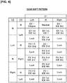
- the gear shift patterns obtainable by the multistage gear transmission 1 having engagement clutches C1, C2, C3 are as shown in Figure 4 .
- “Lock” represents an interlock pattern that is not applicable as a gear shift pattern
- "EV-” represents a state in which the first motor/generator MG1 is not drivingly connected to the driving wheels 19
- "ICE-” represents a state in which the internal combustion engine ICE is not drivingly connected to the driving wheels 19.
- it is not necessary to use all the gear shift patterns shown in Figure 4 and it is of course possible to select from these gear shift patterns according to need.
- Each of the gear shift patterns is described below.
- the gear shift pattern "EV- ICEgen” is a pattern selected at the time of MG1 idle power generation, in which power is generated in the first motor/generator MG1 by the internal combustion engine ICE when the vehicle is stopped, or, at the time of double idle power generation in which MG2 power generation is carried out in addition to MG1 power generation.
- the gear shift pattern "Neutral” is a pattern selected at the time of MG2 idle power generation, in which power is generated in the second motor/generator MG2 by the internal combustion engine ICE when the vehicle is stopped.
- the gear shift pattern "EV1st ICE-” is an "EV mode” pattern in which the internal combustion engine ICE is stopped and traveling is carried out by the first motor/generator MG1, or, a "series HEV mode” pattern in which a first-speed EV traveling is carried out by the first motor/generator MG1 while power is generated in the second motor/generator MG2 by the internal combustion engine ICE.
- the first engagement clutch C1 is switched from the “N” position to the “Left” position, based on a deceleration due to insufficient driving force.
- the vehicle transitions to traveling by the "parallel HEV mode (first speed)" according to the "EV1 st ICE1st” gear shift pattern, in which the driving force is secured.
- the third engagement clutch C3 is switched from the “Left” position to the “Right” position via the "N” position, according to an upshift request.
- the vehicle transitions to traveling by the "parallel HEV mode” according to the "EV2nd ICE2nd” gear shift pattern, in which the EV gear shift stage is set to second speed.
- the second engagement clutch C2 is switched from the “Right" position to the "Left” position via the "N” position, according to a downshift request.
- the vehicle transitions to traveling by the "parallel HEV mode” according to the "EV2nd ICE2nd” gear shift pattern, in which the ICE gear shift stage is set to second speed.
- the gear shift pattern "EV2nd ICE-” is an "EV mode” pattern in which the internal combustion engine ICE is stopped and traveling is carried out by the first motor/generator MG1, or, a "series HEV mode” pattern in which a second-speed EV traveling is carried out by the first motor/generator MG1 while power is generated in the second motor/generator MG2 by the internal combustion engine ICE.
- the second engagement clutch C2 is switched from the “Left” position to the "N” position, and the first engagement clutch C1 is switched from the “N” position to the “Right” position, according to an upshift request.
- the vehicle transitions to traveling by the "parallel HEV mode” according to the "EV2nd ICE3rd” gear shift pattern, in which the ICE gear shift stage is set to third speed.
- Figure 5 illustrates the flow of a shift control process carried out in the transmission control unit 23 (transmission controller) of the embodiment.
- the flowchart of Figure 5 is repeatedly executed at predetermined time intervals.
- Step S1 the transmission control unit 23 determines whether or not a malfunction has occurred in the electric oil pump 20 for lubrication.
- the determination of Step S1 is carried out based on an output of the oil pump rotational speed sensor 78. That is, if the rotational speed of the electric oil pump 20 detected by the oil pump rotational speed sensor 78 is low compared to a control command (target rotational speed) that is input to the electric oil pump 20, the transmission control unit 23 determines that a malfunction has occurred in the electric oil pump 20.
- Step S1 determines whether the electric oil pump 20 is normal. If the determination of Step S1 is NO (the electric oil pump 20 is normal), since it is sufficient to carry out the usual shift control, the following process is skipped. On the other hand, if the determination of Step S1 is YES (a malfunction has occurred in the electric oil pump 20), the process proceeds to Step S2, and the use of ICE1st, ICE3rd, and ICE3rd' as gear shift stages of the internal combustion engine ICE is prohibited.
- Figure 6A illustrates the flow of the MG1 torque and the ICE torque when "EV1st ICE1st” is selected as a gear shift pattern of the parallel HEV mode
- Figure 6B illustrates the flow of the MG1 torque and the ICE torque when "EV2nd ICE3rd" is selected.
- the ICE torque flows from the internal combustion engine ICE ⁇ first shaft 11 ⁇ first gear 101 ⁇ eleventh gear 111 ⁇ fourth shaft 14 ⁇ thirteenth gear 113 ⁇ fourth gear 104 ⁇ second shaft 12 ⁇ fifth gear 105 ⁇ tenth gear 110 ⁇ third shaft 13 ⁇ seventh gear 107 ⁇ sixteenth gear 116 ⁇ differential gear 17 ⁇ drive shaft 18 ⁇ drive wheels 19.
- ICE3rd when ICE3rd is selected as the ICE gear shift stage, as illustrated in Figure 6B , the ICE torque flows from the internal combustion engine ICE ⁇ first shaft 11 ⁇ first gear 101 ⁇ eleventh gear 111 ⁇ fourth shaft 14 ⁇ twelfth gear 112 ⁇ second gear 102 ⁇ sixth gear 106 ⁇ third shaft 13 ⁇ seventh gear 107 ⁇ sixteenth gear 116-differential gear 17 ⁇ drive shaft 18 ⁇ drive wheels 19.
- Figure 7 is a conceptual view for describing the force (surface pressure) that is applied in the radial direction of the second bearing portion 202 provided to the first shaft 11, due to such a flow of the torque.
- Figure 7 illustrates an example of a case in which "EV2nd ICE3rd" is selected (the case of Figure 6B ).
- ICE3rd is selected as the ICE gear shift stage, then the ICE torque flows from the twelfth gear 112 (second power transmission gear) ⁇ second gear 102 (first power transmission gear) ⁇ sixth gear 106 (third power transmission gear). Then, when the ICE torque is transmitted from the twelfth gear 112 to the second gear 102, a force indicated by arrow A in Figure 7 is generated. Then, when the ICE torque is transmitted from the second gear 102 to the sixth gear 106, a force (torque reaction force) indicated by arrow B in Figure 7 is generated. As a result, surface pressure (force indicated by arrow A + force indicated by arrow B) represented by arrow C is applied in the radial direction of the second bearing portion 202, which is interposed between the first shaft 11 and the second gear 102.
- the second bearing portion 202 receives a large surface pressure in the radial direction while being differentially rotated.
- the electric oil pump 20 is operating normally, sufficient lubrication oil is supplied to the second bearing portion 202, and it is possible to prevent seizing of the second bearing portion 202 and damage thereto.
- a malfunction occurs in the electric oil pump 20 and sufficient lubrication oil cannot be supplied to the second bearing portion 202, then there is a risk that seizing or damage will occur in the second bearing portion 202.
- the ICE torque flows from the thirteenth gear 113 (fifth power transmission gear) ⁇ fourth gear 104 (fourth power transmission gear) ⁇ second shaft 12 ⁇ fifth gear 105 (fourth power transmission gear) ⁇ tenth gear 110 (sixth power transmission gear). Then, as described with reference to Figure 7 , the fourth bearing portion 204 and the fifth bearing portion 205, which are interposed between the second shaft 12 and the first shaft 11, receive a large surface pressure in the radial direction while being differentially rotated. Therefore, if a malfunction occurs in the electric oil pump 20 in such a state, then there is a risk that seizing or damage will occur in the fourth bearing portion 204 and the fifth bearing portion 205.
- ICE3rd' is selected as the ICE gear shift stage. That is, if ICE3rd' is selected as the ICE gear shift stage, the fourth bearing portion 204 receives a large surface pressure in the radial direction while being differentially rotated. Therefore, if a malfunction occurs in the electric oil pump 20 in such a state, then there is a risk that seizing or damage will occur in the fifth bearing portion 205.
- Figure 8A illustrates a case in which "EV2nd ICE2nd” is selected as the gear shift pattern
- Figure 8B illustrates a case in which "EV2nd ICE4th" is selected as the gear shift pattern.
- differential rotation means the differential rotation between a bearing portion, and a rotational shaft that is supported by the bearing portion.
- Step S3 it is determined whether or not the remaining battery SOC (State of Charge) of the high-power battery 3 is equal to or greater than a threshold value.
- the threshold value in Step S3 is set to a value with which it is possible to determine whether or not "EV mode," in which the internal combustion engine ICE is stopped and the vehicle travels only by the first motor/generator MG1, is possible.
- Step S3 determines whether the remaining battery SOC of the high-power battery 3 is equal to or greater than the threshold value. If the determination of Step S3 is YES (remaining battery SOC of the high-power battery 3 is equal to or greater than the threshold value), that is, if it is determined that traveling by the "EV mode" is possible, then the process proceeds to Step S4, and the internal combustion engine ICE is stopped.
- the reason why the "EV mode" is selected if the remaining battery SOC of the high-power battery 3 is equal to or greater than a threshold value will be described with reference to Figure 9 , etc.
- Figure 9 illustrates the flow of the MG1 torque when the "EV mode” (more specifically, the "EV2nd ICE-” gear shift pattern) is selected.
- the rotary elements that are connected to the internal combustion engine ICE (specifically, the first shaft 11, the first gear 101, the eleventh gear 111, the fourth shaft 14, the fourteenth gear 114, the fifth shaft 15, the fifteenth gear 115, and the sixth shaft 16) are not rotated together with the internal combustion engine ICE.
- the first engagement clutch C1 and the second engagement clutch C2 are released, the rotary elements described above also will not be rotated together with the first motor/generator MG1.
- the eleventh bearing portion 211 which supports the first shaft 11 to the transmission case 10
- the fourteenth bearing portion 214 which supports the fourth shaft to the transmission case 10
- the sixteenth bearing portion 216 which supports the sixth shaft 16 to the transmission case 10
- the eleventh and fourteenth bearing portions 211, 214 are lubricated, not by lubrication oil that is supplied from the electric oil pump 20, but by lubrication oil that is scraped up from an oil pan (not shown) by the differential gear 17, or the like.
- the "EV mode" is selected, in which the number of bearing portions that are differentially rotated is small (that is, the load of the lubricated parts as a whole is small).
- Step S5 EV2nd is selected as the EV gear shift stage (that is, the gear shift pattern of the multistage gear transmission 1 is set to "EV2nd ICE-"), and the program is ended.
- Figure 10 illustrates the differential rotational speed of the fourth and fifth bearing portions 214, 215, when "EV mode" is selected in the multistage gear transmission 1 of the present embodiment.
- the differential rotational speed of the fourth and fifth bearing portions 214, 215 in the "EV mode" becomes smaller when selecting EV2nd, compared to when selecting EV1st.
- a large differential rotational speed means that the required amount of lubrication oil is large. Therefore, it can be seen that the required amount of lubrication oil is smaller when selecting EV2nd (that is, the load of the lubricated parts as a whole is small).
- EV2nd is selected as the EV gear shift stage.
- Step S3 determines whether or not the vehicle speed VSP is equal to or greater than a first predetermined speed. If the determination of Step S7 is YES (vehicle speed VSP ⁇ first predetermined speed), the process proceeds to Step S8, the gear shift pattern of the multistage gear transmission 1 is set to "EV2nd ICE4th,” and the program is ended.
- Step S7 determines whether or not the vehicle speed VSP is equal to or greater than a second predetermined speed that is slower than the first predetermined speed. If the determination of Step S9 is YES (vehicle speed VSP ⁇ second predetermined speed), then the process proceeds to Step S10, then the gear shift pattern of the multistage gear transmission 1 is set to "EV2nd ICE2nd," and the program is ended. In contrast, if the determination of Step S9 is NO (vehicle speed VSP ⁇ second predetermined speed), the process proceeds to Step S11, then the vehicle is stopped, and the program is ended.
- Figure 11 illustrates the relationship between the differential rotational speed of the bearing portions (fourth and fifth bearing portions 214, 215) in the case where the "EV2nd ICE2nd" or the "EV2nd ICE4th" gear shift pattern is selected in the multistage gear transmission 1 of the embodiment.
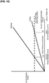
- Figure 12 illustrates the shifting map of the multistage gear transmission 1 of the embodiment, in a case where a malfunction has occurred in the electric oil pump 20.
- the differential rotational speed of the fourth and fifth bearing portions 214, 215 becomes smaller when selecting ICE4th, compared to when selecting ICE2nd. That is, it can be seen that the required amount of lubrication oil is smaller when selecting ICE4th (that is, the load of the lubricated parts as a whole is small). Therefore, if a malfunction has occurred in the electric oil pump 20 for lubrication, then it is preferable to select ICE4th insofar as possible.
- ICE4th is selected when the vehicle speed VSP is less than the first predetermined speed, then the rotational speed of the internal combustion engine ICE falls below the travelable rotational speed, as illustrated in Figure 12 .
- ICE4th is selected when the vehicle speed VSP is equal to or greater than the first predetermined speed.
- ICE2nd is selected when the vehicle speed VSP is less than the second predetermined speed, then the rotational speed of the internal combustion engine ICE falls below the travelable rotational speed.
- ICE2nd is selected when the vehicle speed VSP is less than the second predetermined speed.
- the vehicle speed VSP is equal to or greater than the first predetermined speed, that is, if a plurality of gear shift stages (ICE2nd, ICE4th) can be selected as the ICE gear shift stage, ICE4th, in which the differential rotational speed of the bearing portions (the fourth and fifth bearing portions 214, 215) is small, is selected (Step S6 ⁇ Step S7). Since the differential rotational speed of the fourth and fifth bearing portions 214, 215 is smaller when selecting EV2nd, as described above, EV2nd is selected as the EV gear shift stage (that is, the transmission control unit 23 selects the "EV2nd ICE4th" gear shift pattern).
- ICE2nd is selected (Step S7 ⁇ Step S9 ⁇ Step S10).
- EV2nd is selected as the EV gear shift stage (that is, the transmission control unit 23 selects the "EV2nd ICE2nd" gear shift pattern).
- the rotational speed of the internal combustion engine ICE falls below the travelable rotational speed, regardless of whether ICE2nd or ICE4th is selected. Therefore, in such a case, the vehicle is promptly stopped.
- Step S1-Step S2 ⁇ Step S3 ⁇ Step S4 ⁇ Step S5 in the flowchart of Figure 5 That is, ICE1st, ICE3rd, and ICE3rd' are prohibited as the gear shift stage of the internal combustion engine ICE, the internal combustion engine ICE is stopped, and the vehicle travels in EV2nd (that is, the "EV2nd ICE-" gear shift pattern).
- Step S11 ICE2nd or ICE4th is selected in accordance with the vehicle speed VSP (that is, the "EV2nd ICE2nd" or the "EV2nd ICE4th" gear shift pattern is selected). Additionally, if the vehicle speed VSP is less than the second predetermined speed, the vehicle is stopped (Step S11).
- the action of the shift control process described above will be described on the basis of the time chart of Figure 13 .
- the time chart of Figure 13 assumes a state in which the vehicle is traveling with the "EV2nd ICE3rd" gear shift pattern.
- the internal combustion engine ICE is restarted (time t4).
- the second engagement clutch is shifted from the "N" position to the "Right" position from time t5 to time t6, and the "EV2nd ICE4th" gear shift pattern is selected (that is, the vehicle is put in the "parallel HEV mode").
- a gear shift pattern (power transmission path) having a small load on the lubricated gears (101-105, etc.) and bearing portions (202, 203, 204, 205, etc.) is selected upon detecting a malfunction has occurred in the electric oil pump 20 for lubrication.
- a path is selected in which the force that is applied in the radial direction of the bearing portions (the second to the fifth bearing portions 202-205) is small.
- a path is selected in which the number of bearing portions that are differentially rotated is small (the second to the fifth bearing portions 202-205, the eleventh and the fourteenth to the sixteenth bearing portions 211, 214-216).
- the EV mode is selected as long as the remaining battery SOC of the high-power battery 3 is equal to or greater than a threshold value. Therefore, it is possible to stop the rotation of rotary elements (the eleventh bearing portion 211, the fourteenth bearing portion 214, the fifteenth bearing portion 215, and the sixteenth bearing portion 216) that are differentially rotated due to the rotation of the internal combustion engine ICE.
- a path is selected whereby traveling of the vehicle is possible, and the differential rotational speed of the bearing portions (the second and third bearing portions 202, 203, and the fourth and fifth bearing portions 204, 205) is small.
- the differential rotational speed in the fourth and fifth bearing portions 204, 205 is smaller, and the required amount of lubrication oil is smaller, when in EV2nd than when in EV1 st, as illustrated in Figure 10 . Therefore, EV2nd is selected as the EV gear shift stage.
- ICE4th is selected when the vehicle speed VSP is equal to or greater than the first predetermined speed, and both ICE2nd and ICE4th can be selected.
- the transmission control device of the present invention may be applied to any vehicle using a transmission having a gear-shifting mechanism, and may be applied to a vehicle having only an internal combustion engine as a drive source.
- a multistage gear transmission 1 comprising EV first to second speeds as EV gear shift stages, and ICE first to fourth speeds as ICE gear shift stages.
- the transmission control device of the present invention can be applied to any transmission having a gear-shifting mechanism that obtains a plurality of gear shift stages by selecting a plurality of power transmission paths, and the configuration of the multistage gear transmission is not limited to the embodiment.
Abstract
Description
- The present invention relates to a vehicle transmission control device comprising an oil pump that supplies lubrication oil to a gear-shifting mechanism.
- An example of a vehicle transmission control device comprising an oil pump that supplies lubrication oil to a transmission mechanism is a technique disclosed in
Patent Document 1. In the technique disclosed inPatent Document 1, an electric oil pump that supplies lubrication oil to lubricated parts of a gear type shifting mechanism is provided, and the discharge amount of the electric oil pump is controlled in accordance with the operating state of the vehicle. By employing such a configuration, the technique disclosed inPatent Document 1 improves the design flexibility of the transmission, and prevents seizing of lubricated parts and damage thereto. - Patent Document 1: Japanese Laid Open Patent Application No.
Hei 4(1992)-285358 - However upon detecting a malfunction has occurred in the oil pump that supplies lubrication oil, if an ordinary shift control is continued, there is a risk that seizing of the lubricated parts and damage thereto will occur due to poor lubrication.
- In view of the problems described above, an object of the present invention is to provide a vehicle transmission control device in a vehicle provided with an oil pump for supplying lubricating oil to a gear-shifting mechanism, which is configured to be able to prevent seizing of lubricated parts and damage thereto, if a malfunction occurs in the oil pump.
- In order to achieve the object described above, a vehicle of the present invention comprises a transmission having a gear-shifting mechanism that obtains a plurality of gear shift stages by selecting a plurality of power transmission paths, and an oil pump that supplies lubrication oil to lubricated parts of the gear-shifting mechanism.
- In addition, the transmission control device of the present invention is provided with a transmission controller for selecting a plurality of power transmission paths.
- The transmission controller selects a path having a small load on the lubricated parts from among a plurality of power transmission paths upon detecting a malfunction has occurred in the oil pump.
- Therefore upon detecting a malfunction has occurred in the oil pump, a power transmission path having a small load on the lubricated parts is selected.
- That is, in a normal shift control based on a gear shift request, there are cases in which a power transmission path having a large load on the lubricated part is selected. Consequently, if such a shift control is maintained when a malfunction occurs in the oil pump, there is a risk that seizing and damage will occur in the lubricated parts.
- In contrast, in the present invention, a power transmission path having a small load on the lubricated parts is selected upon detecting a malfunction has occurred in the oil pump.
- As a result, it is possible to prevent seizing and damage in the lubricated parts, even if a malfunction occurs in the lubricating oil pump.
-
- [
Figure 1 ] is an overall system view illustrating a drive system and a control system of a vehicle to which is applied the transmission control device of the embodiment. - [
Figure 2 ] is a schematic overview illustrating the configuration of a transmission mounted on a vehicle to which is applied the transmission control device of the embodiment. - [
Figure 3 ] is a schematic overview of a shifting map illustrating a concept of switching the gear shift pattern in a transmission mounted on a vehicle to which is applied the transmission control device of the embodiment. - [
Figure 4 ] is a gear shift pattern view illustrating the gear shift patterns according to the switching positions of three engagement clutches in a transmission mounted on a vehicle to which is applied the transmission control device of the embodiment. - [
Figure 5 ] is a flowchart illustrating the flow of a shift control process carried out in a transmission control unit of the embodiment. - [
Figure 6A ] is a torque flow view illustrating the flow of the MG1 torque and the ICE torque in a transmission when the "EV1 st ICE1st" gear shift pattern is selected. - [
Figure 6B ] is a torque flow view illustrating the flow of the MG1 torque and the ICE torque in a transmission when the "EV2nd ICE3rd" gear shift pattern is selected. - [
Figure 7 ] is an explanatory view describing the force that is applied in the radial direction of the bearing portion, in a transmission mounted on a vehicle to which is applied the transmission control device of the embodiment. - [
Figure 8A ] is a torque flow view illustrating the flow of the MG1 torque and the ICE torque in a transmission when the "EV2nd ICE2nd" gear shift pattern is selected. - [
Figure 8B ] is a torque flow view illustrating the flow of the MG1 torque and the ICE torque in a transmission when the "EV2nd ICE4th" gear shift pattern is selected. - [
Figure 9 ] is a torque flow view illustrating the flow of the MG1 torque in a transmission when the "EV2nd ICE-" gear shift pattern is selected. - [
Figure 10 ] is an explanatory view describing the relationship between the EV gear shift stage and the differential rotational speed of the bearing portion, in a transmission mounted on a vehicle to which is applied the transmission control device of the embodiment. - [
Figure 11 ] is an explanatory view describing the relationship between the ICE gear shift stage and the differential rotational speed of the bearing portion, in a transmission mounted on a vehicle to which is applied the transmission control device of the embodiment. - [
Figure 12 ] is a schematic overview of a shifting map illustrating a concept of switching the ICE gear shift stage when a malfunction occurs in the lubricating oil pump, in a transmission mounted on a vehicle to which is applied the transmission control device of the embodiment. - [
Figure 13 ] is a time chart illustrating each characteristic at the time of executing the flowchart ofFigure 5 . - A preferred embodiment for realizing the vehicle transmission control device of the present invention is described below based on the embodiment illustrated in the drawings.
- The configuration is described first.
- The transmission control device of the embodiment is applied to a hybrid vehicle (one example of an electrically driven vehicle), comprising, as drive system components, one engine, two motor/generators, and a multistage gear transmission having three engagement clutches. The "overall system configuration," the "configuration of the transmission," the "configuration of the gear shift patterns," and the "configuration of the shift control process" will be separately described below, regarding the configuration of the transmission control device for a hybrid vehicle in the embodiment.
-
Figure 1 illustrates a drive system and a control system of a vehicle (hybrid vehicle) to which is applied the transmission control device of the embodiment. The overall system configuration will be described below, based onFigure 1 . - The drive system of the hybrid vehicle comprises an internal combustion engine ICE, a first motor/generator MG1, a second motor/generator MG2, and a
multistage gear transmission 1 having three engagement clutches C1, C2, //C3//, as illustrated inFigure 1 . "ICE" is an acronym for "Internal Combustion Engine." - The internal combustion engine ICE is, for example, a gasoline engine or a diesel engine that is disposed in a front room of a vehicle such that the crankshaft direction is in the vehicle width direction. This internal combustion engine ICE is connected to a
transmission case 10 of themultistage gear transmission 1, and the output shaft of the internal combustion engine is connected to a first shaft 11 (first gear shaft) of themultistage gear transmission 1. The internal combustion engine ICE basically carries out an MG2 start, where the second motor/generator MG2 is used as a starter motor. However, astarter motor 2 is left in preparation for when an MG2 start using a high-power battery 3 cannot be ensured, such as during extreme cold. - Both the first motor/generator MG1 and the second motor/generator MG2 are permanent magnet type synchronous motors utilizing a three-phase alternating current, having the high-
power battery 3 as a common power source. The stator of the first motor/generator MG1 is fixed to a case of the first motor/generator MG1, and the case is fixed to thetransmission case 10 of themultistage gear transmission 1. Then, a first motor shaft integrated to a rotor of the first motor/generator MG1 is connected to asecond shaft 12 of themultistage gear transmission 1. The stator of the second motor/generator MG2 is fixed to a case of the second motor/generator MG2, and the case is fixed to thetransmission case 10 of themultistage gear transmission 1. Then, a second motor shaft integrated to a rotor of the second motor/generator MG2 is connected to asixth shaft 16 of themultistage gear transmission 1. A first inverter 4, which converts direct current to three-phase alternating current during powering and converts three-phase alternating current to direct current during regeneration, is connected to a stator coil of the first motor/generator MG1, via afirst AC harness 5. A second inverter 6, which converts direct current to three-phase alternating current during powering and converts three-phase alternating current to direct current during regeneration, is connected to a stator coil of the second motor/generator MG2, via asecond AC harness 7. The high-power battery 3, the first inverter 4, and the second inverter 6 are connected by aDC harness 8, via ajunction box 9. - The
multistage gear transmission 1 is a normally meshing transmission comprising a plurality of gear pairs having different transmission ratios, and comprises six gear shafts 11-16 provided with gears and disposed parallel to each other inside thetransmission case 10, and three engagement clutches C1, C2, C3 for selecting a gear pair. Afirst shaft 11, asecond shaft 12, athird shaft 13, afourth shaft 14, afifth shaft 15, and asixth shaft 16 are provided as gear shafts. A first engagement clutch C1, a second engagement clutch C2, and a third engagement clutch C3 are provided as engagement clutches. Thetransmission case 10 is provided with an electric oil pump (oil pump) 20 that supplies lubrication oil to the meshing portions of the gears and the bearing portions (bearing) inside the case. - The
first shaft 11 is a shaft to which the internal combustion engine ICE is connected, and afirst gear 101, a second gear 102 (first power transmission gear), and athird gear 103 are disposed on thefirst shaft 11, in order from the right side inFigure 1 . Thefirst gear 101 is integrally provided (including integral fixing) to thefirst shaft 11. Thesecond gear 102 and thethird gear 103 are idling gears, in which a boss portion that protrudes in the axial direction is inserted onto the outer perimeter of thefirst shaft 11, and are provided so as to be drivably connectable to thefirst shaft 11 via the second engagement clutch C2. - The second shaft 12 (second gear shaft) is a shaft to which the first motor/generator MG1 is connected, and is a hollow cylindrical shaft coaxially disposed with the axis aligned with the outer side position of the
first shaft 11, and a fourth gear 104 (fourth power transmission gear) and a fifth gear 105 (fourth power transmission gear) are disposed on thesecond shaft 12, in order from the right side inFigure 1 . Thefourth gear 104 and thefifth gear 105 are integrally provided (including integral fixing) to thesecond shaft 12. - The
third shaft 13 is a shaft disposed on the output side of themultistage gear transmission 1, and a sixth gear 106 (third power transmission gear), aseventh gear 107, aneighth gear 108, a ninth gear 109 (sixth power transmission gear), and a tenth gear 110 (sixth power transmission gear) are disposed on thethird shaft 13, in order from the right side inFigure 1 . Thesixth gear 106, theseventh gear 107, and theeighth gear 108 are integrally provided (including integral fixing) to thethird shaft 13. Theninth gear 109 and thetenth gear 110 are idling gears, in which boss portions protruding in the axial direction are inserted onto the outer perimeter of thethird shaft 13, and are provided so as to be drivably connectable to thethird shaft 13 via the third engagement clutch C3. Then, thesixth gear 106 meshes with thesecond gear 102 of thefirst shaft 11, theseventh gear 107 meshes with asixteenth gear 116 of adifferential gear 17, and theeighth gear 108 meshes with thethird gear 103 of thefirst shaft 11. Theninth gear 109 meshes with thefourth gear 104 of thesecond shaft 12, and thetenth gear 110 meshes with thefifth gear 105 of thesecond shaft 12. - The
fourth shaft 14 has both ends supported on thetransmission case 10, with aneleventh gear 111, a twelfth gear 112 (second power transmission gear), and a thirteenth gear 113 (fifth power transmission gear) are disposed on thefourth shaft 14, in order from the right side inFigure 1 . Theeleventh gear 111 is integrally provided (including integral fixing) to thefourth shaft 14. Thetwelfth gear 112 and thethirteenth gear 113 are idling gears, in which a boss portion protruding in the axial direction is inserted onto the outer perimeter of thefourth shaft 14, and are provided so as to be drivably connectable to thefourth shaft 14 via the first engagement clutch C1. Then, theeleventh gear 111 meshes with thefirst gear 101 of thefirst shaft 11, thetwelfth gear 112 meshes with asecond gear 102 of thefirst shaft 11, and thethirteenth gear 113 meshes with thefourth gear 104 of thesecond shaft 12. - The
fifth shaft 15 has both ends are supported on thetransmission case 10, and afourteenth gear 114 that meshes with theeleventh gear 111 of thefourth shaft 14 is integrally provided thereto (including integral fixing). - The
sixth shaft 16 is connected to the second motor/generator MG2, and afifteenth gear 115 that meshes with thefourteenth gear 114 of thefifth shaft 15 is integrally provided thereto (including integral fixing). - The second motor/generator MG2 and the internal combustion engine ICE are mechanically connected to each other by a gear train configured from the
fifteenth gear 115, thefourteenth gear 114, theeleventh gear 111, and thefirst gear 101, which mesh with each other. This gear train serves as a reduction gear train that decelerates the MG2 rotational speed at the time of an MG2 start of the internal combustion engine ICE by the second motor/generator MG2, and serves as a speed increasing gear train that accelerates the engine rotational speed at the time of MG2 power generation for generating the second motor/generator MG2, by the driving of the internal combustion engine ICE. - The first engagement clutch C1 is a dog clutch interposed between the
twelfth gear 112 and thethirteenth gear 113 of thefourth shaft 14, and that is engaged by an engagement movement in a rotation synchronization state by not having a synchronization mechanism. When the first engagement clutch C1 is in a left engagement position (Left), thefourth shaft 14 and thethirteenth gear 113 are drivingly connected. When the first engagement clutch C1 is in a neutral position (N), thefourth shaft 14 and thetwelfth gear 112 are released, and thefourth shaft 14 and thethirteenth gear 113 are released. When the first engagement clutch C1 is in a right engagement position (Right), thefourth shaft 14 and thetwelfth gear 112 are drivingly connected. - The second engagement clutch C2 is a dog clutch interposed between the
second gear 102 and thethird gear 103 of thefirst shaft 11, and that is engaged by an engagement movement in a rotation synchronization state by not having a synchronization mechanism. When the second engagement clutch C2 is in a left engagement position (Left), thefirst shaft 11 and thethird gear 103 are drivingly connected. When the second engagement clutch C2 is in a neutral position (N), thefirst shaft 11 and thesecond gear 102 are released, and thefirst shaft 11 and thethird gear 103 are released. When the second engagement clutch C2 is in a right engagement position (Right), thefirst shaft 11 and thesecond gear 102 are drivingly connected. - The third engagement clutch C3 is a dog clutch interposed between the
ninth gear 109 and thetenth gear 110 of thethird shaft 13, and that is engaged by an engagement movement in a rotation synchronization state by not having a synchronization mechanism. When the third engagement clutch C3 is in a left engagement position (Left), thethird shaft 13 and thetenth gear 110 are drivingly connected. When the third engagement clutch C3 is in a neutral position (N), thethird shaft 13 and theninth gear 109 are released, and thethird shaft 13 and thetenth gear 110 are released. When the third engagement clutch C3 is in a right engagement position (Right), thethird shaft 13 and theninth gear 109 are drivingly connected. Then, asixteenth gear 116 that meshes with theseventh gear 107 integrally provided (including integral fixing) to thethird shaft 13 of themultistage gear transmission 1 is connected to left andright drive wheels 19 via thedifferential gear 17 and left andright drive shafts 18. - The control system of the hybrid vehicle comprises a
hybrid control module 21, amotor control unit 22, atransmission control unit 23, and anengine control unit 24, as illustrated inFigure 1 . - The hybrid control module 21 (acronym: "HCM") is an integrated control means to appropriately manage the energy consumption of the entire vehicle. This
hybrid control module 21 is connected to the other control units (motor control unit 22,transmission control unit 23,engine control unit 24, etc.) so as to be capable of bidirectional information exchange by aCAN communication line 25. The "CAN" inCAN communication line 25 is an acronym for "Controller Area Network." - The motor control unit 22 (acronym: "MCU") carries out powering control, regeneration control, and the like, of the first motor/generator MG1 and the second motor/generator MG2, by control commands to the first inverter 4 and the second inverter 6. The control modes for the first motor/generator MG1 and the second motor/generator MG2 are "torque control" and "rotational speed FB control." In the "torque control," a control is carried out in which the actual motor torque is caused to follow a target motor torque, when a target motor torque to be shared with respect to a target drive force is determined. In the "rotational speed FB control," a control is carried out in which a target motor rotational speed, with which the input/output rotational speeds of the clutch are synchronized, is determined, and an FB torque is output so as to converge the actual motor rotational speed to the target motor rotational speed, when there is a gear shift request to mesh and engage any one of the engagement clutches C1, C2, C3 during traveling.
- The transmission control unit 23 (acronym "TMCU") carries out a shift control for switching the gear shift pattern (power transmission path) of the
multistage gear transmission 1, by outputting a current command to electric actuators 31, 32, 33 (not shown) of the first, second, and third engagement clutches C1, C2, C3, based on predetermined input information. In this shift control, the engagement clutches C1, C2, C3 are selectively mesh engaged/released, and a gear pair involved in power transmission is selected from the plurality of pairs of gear pairs. Here, at the time of a gear shift request to engage any one of the released engagement clutches C1, C2, C3, in order to suppress differential rotational speed between the input/output of the clutch to ensure meshing engagement, a rotational speed FB control (rotation synchronization control) of the first motor/generator MG1 or the second motor/generator MG2 is used in combination. - The
transmission control unit 23 inputs sensor signals and switch signals from avehicle speed sensor 71, an accelerator position openingamount sensor 72, a transmission output shaft rotational speed sensor 73, an enginerotational speed sensor 74, an MG1rotational speed sensor 75, an MG2rotational speed sensor 76, aninhibitor switch 77, an oil pumprotational speed sensor 78, and the like. The transmission output shaft rotational speed sensor 73 is provided to the shaft end portion of thethird shaft 13 and detects the shaft rotational speed of thethird shaft 13. Thetransmission control unit 23 determines whether or not a malfunction has occurred in theelectric oil pump 20, based on a sensor signal of the oil pumprotational speed sensor 78. The determination of whether or not a malfunction has occurred in theelectric oil pump 20 is not limited to an oil pumprotational speed sensor 78, and, for example, may be determined by providing a hydraulic pressure sensor to theelectric oil pump 20, by providing a temperature sensor to the lubricated parts described later, or by a combination thereof. That is, if a malfunction occurs in theelectric oil pump 20, the discharge pressure of theelectric oil pump 20 decreases while the temperature of the lubricated parts increases; it is thereby also possible to determine a malfunction in theelectric oil pump 20 based on these changes. - The engine control unit 24 (acronym "ECU") carries out start control of the internal combustion engine ICE, stop control of the internal combustion engine ICE, fuel cut control, and the like, by outputting a control command to the
motor control unit 22, a spark plug, a fuel injection actuator, or the like, based on predetermined input information. - The
multistage gear transmission 1 according to the embodiment is characterized in that efficiency is obtained by reducing drag by employing, as shifting elements, engagement clutches C1, C2, C3 (dog clutch) that are meshingly engaged. Then, when there is a gear shift request to mesh and engage any one of the engagement clutches C1, C2, C3, the differential rotational speeds of the input/output of the clutch are synchronized by the first motor/generator MG1 (when the engagement clutch C3 is engaged) or the second motor/generator MG2 (when the engagement clutches C1, C2 are engaged), and an engagement movement is started once the rotational speed falls within a synchronization determination rotational speed range, to realize the gear shift. In addition, when there is a gear shift request to release any one of the engaged engagement clutches C1, C2, C3, the clutch transmission torque of the release clutch is reduced, and a disengagement movement is started once the torque becomes equal to or less than a release torque determination value, to realize the gear shift. -
Figure 2 is a cross-sectional view of themultistage gear transmission 1 of the embodiment. The configuration of thetransmission 1 of the embodiment will be described below, based onFigure 2 . - In the
multistage gear transmission 1 of the embodiment, thesecond gear 102 and thethird gear 103 are disposed on the outer perimeter side of thefirst shaft 11, which is connected to the output shaft of the internal combustion engine ICE, via asecond bearing portion 202 and athird bearing portion 203, respectively, as illustrated inFigure 2 . Thefirst shaft 11 is supported to thetransmission case 10 by theeleventh bearing portion 211, and is supported inside thesecond shaft 12, which is a cylindrical shaft, by thefourth bearing portion 204 and thefifth bearing portion 205. Here, thefourth bearing portion 204 is interposed between thefirst shaft 11 and thefourth gear 104, which is integrally provided with thesecond shaft 12. In addition, thefifth bearing portion 205 is interposed between thefirst shaft 11 and thefifth gear 105, which is integrally provided with thesecond shaft 12. Additionally, thesecond shaft 12 is supported to thetransmission case 10 by thetwelfth bearing portion 212. - The
fourth shaft 14 is supported to thetransmission case 10 by thefourteenth bearing portion 214. Thefifth shaft 15 is supported to thetransmission case 10 by thefifteenth bearing portion 215. Additionally, thesixth shaft 16 is supported to thetransmission case 10 by thesixteenth bearing portion 216. - The
electric oil pump 20 supplies lubrication oil to the bearing portions and gears described above. Specifically, the discharge passage (not shown) of theelectric oil pump 20 is connected to alubrication oil passage 11a provided inside thefirst shaft 11, and the lubrication oil that is discharged from theelectric oil pump 20 is supplied to each bearing portion (202, 203, 204, 205, and the like) and each gear (101-105, and the like) via thelubrication oil passage 11a of thefirst shaft 11. - In addition, the discharge passage (not shown) of the
electric oil pump 20 is also connected to an oil chamber (not shown) provided in the vicinity of thesixth shaft 16, and the lubrication oil that is stored in the oil chamber is supplied to the fifteenth and sixteenth bearingportions multistage gear transmission 1 comprises a plurality of bearing portions and gears in addition to the above, as illustrated inFigure 2 , but detailed descriptions of the other configurations are omitted. In addition, in the present Specification, rotating elements to which lubrication oil is supplied, such as the plurality of bearing portions (22nd andthird bearing portions second gears - The
multistage gear transmission 1 of the first embodiment is characterized in that size reduction is obtained by reducing the power transmission loss by not having a differential rotation absorbing element, such as a fluid coupling, and by reducing ICE gear shift stages (gear shift stages of the internal combustion engine ICE) by providing motor assistance to the internal combustion engine ICE (EV gear shift stages: 1-2 speed, ICE gear shift stages: 1-4 speed). The configuration of the gear shift pattern of themultistage gear transmission 1 is described below based onFigure 3 andFigure 4 . - A concept of a gear shift pattern is employed in which, when the vehicle speed VSP is in a starting region equal to or less than a predetermined vehicle speed VSP0, since the
multistage gear transmission 1 does not have a differential rotation absorbing element, a motor start by only the motor driving force is carried out in the "EV mode" (more precisely, EV 1st, which is the first speed of the EV gear shift stage) as illustrated inFigure 3 . Then, when in the traveling region and the demand for driving force is great, a "parallel HEV mode" is employed in which the engine driving force is assisted by the motor driving force, as illustrated inFigure 3 . That is, as the vehicle speed VSP increases, the ICE gear shift stages shift from (ICE 1st) → ICE 2nd → ICE 3rd → ICE 4th, and the EV gear shift stages (gear shift stages of the first motor/generator MG1) shift from EV 1st → EV 2nd. Therefore, based on the concept of the gear shift pattern illustrated inFigure 3 , a shifting map for issuing gear shift requests for switching the gear shift pattern is created. - The gear shift patterns obtainable by the
multistage gear transmission 1 having engagement clutches C1, C2, C3 are as shown inFigure 4 . InFigure 4 , "Lock" represents an interlock pattern that is not applicable as a gear shift pattern, "EV-" represents a state in which the first motor/generator MG1 is not drivingly connected to the drivingwheels 19, and "ICE-" represents a state in which the internal combustion engine ICE is not drivingly connected to the drivingwheels 19. In the shift control, it is not necessary to use all the gear shift patterns shown inFigure 4 , and it is of course possible to select from these gear shift patterns according to need. Each of the gear shift patterns is described below. - When the second engagement clutch C2 is in the "N" position and the third engagement clutch C3 is in the "N" position, the following gear shift patterns are obtained according to the position of the first engagement clutch C1. "EV- ICEgen" is obtained if the first engagement clutch C1 is in the "Left" position, "Neutral" is obtained if the first engagement clutch C1 is in the "N" position, and "EV- ICE3rd" is obtained if the first engagement clutch C1 is in the "Right" position.
- Here, the gear shift pattern "EV- ICEgen" is a pattern selected at the time of MG1 idle power generation, in which power is generated in the first motor/generator MG1 by the internal combustion engine ICE when the vehicle is stopped, or, at the time of double idle power generation in which MG2 power generation is carried out in addition to MG1 power generation. The gear shift pattern "Neutral" is a pattern selected at the time of MG2 idle power generation, in which power is generated in the second motor/generator MG2 by the internal combustion engine ICE when the vehicle is stopped.
- When the second engagement clutch C2 is in the "N" position and the third engagement clutch C3 is in the "Left" position, the following gear shift patterns are obtained according to the position of the first engagement clutch C1. "EV1st ICE1st" is obtained if the first engagement clutch C1 is in the "Left" position, "EV1st ICE-" is obtained if the first engagement clutch C1 is in the "N" position, and "EV1st ICE3rd" is obtained if the first engagement clutch C1 is in the "Right" position.
- Here, the gear shift pattern "EV1st ICE-" is an "EV mode" pattern in which the internal combustion engine ICE is stopped and traveling is carried out by the first motor/generator MG1, or, a "series HEV mode" pattern in which a first-speed EV traveling is carried out by the first motor/generator MG1 while power is generated in the second motor/generator MG2 by the internal combustion engine ICE.
- For example, when traveling while selecting the "series HEV mode" by "EV1st ICE-," the first engagement clutch C1 is switched from the "N" position to the "Left" position, based on a deceleration due to insufficient driving force. In this case, the vehicle transitions to traveling by the "parallel HEV mode (first speed)" according to the "EV1 st ICE1st" gear shift pattern, in which the driving force is secured.
- When the second engagement clutch C2 is in the "Left" position and the third engagement clutch C3 is in the "Left" position, "EV1st ICE2nd" is obtained if the first engagement clutch C1 is in the "N" position.
- For example, if the driving force requirement is increased during first-speed EV traveling while selecting the "series HEV mode" by "EV 1st ICE-," the second engagement clutch C2 is switched from "N" to "Left." In this case, the vehicle transitions to traveling by a "parallel HEV mode" according to the "EV1 st ICE2nd" gear shift pattern, in which the driving force is secured.
- When the second engagement clutch C2 is in the "Left" position and the third engagement clutch C3 is in the "N" position, the following gear shift patterns are obtained according to the position of the first engagement clutch C1. "EV1.5 ICE2nd" is obtained if the first engagement clutch C1 is in the "Left" position, and "EV- ICE2nd" is obtained if the first engagement clutch C1 is in the "N" position.
- When the second engagement clutch C2 is in the "Left" position and the third engagement clutch C3 is in the "Right" position, "EV2nd ICE2nd" is obtained if the first engagement clutch C1 is in the "N" position.
- For example, when traveling in the "parallel HEV mode" while selecting the "EV1st ICE2nd" gear shift pattern, the third engagement clutch C3 is switched from the "Left" position to the "Right" position via the "N" position, according to an upshift request. In this case, the vehicle transitions to traveling by the "parallel HEV mode" according to the "EV2nd ICE2nd" gear shift pattern, in which the EV gear shift stage is set to second speed.
- For example, when traveling in the "parallel HEV mode" while selecting the "EV2nd ICE4th" gear shift pattern, the second engagement clutch C2 is switched from the "Right" position to the "Left" position via the "N" position, according to a downshift request. In this case, the vehicle transitions to traveling by the "parallel HEV mode" according to the "EV2nd ICE2nd" gear shift pattern, in which the ICE gear shift stage is set to second speed.
- When the second engagement clutch C2 is in the "N" position and the third engagement clutch C3 is in the "Right" position, the following gear shift patterns are obtained according to the position of the first engagement clutch C1. "EV2nd ICE3rd"' is obtained if the first engagement clutch C1 is "Left," "EV2nd ICE-" is obtained if the first engagement clutch C1 is "N," and "EV2nd ICE3rd" is obtained if the first engagement clutch C1 is "Right."
- Here, the gear shift pattern "EV2nd ICE-" is an "EV mode" pattern in which the internal combustion engine ICE is stopped and traveling is carried out by the first motor/generator MG1, or, a "series HEV mode" pattern in which a second-speed EV traveling is carried out by the first motor/generator MG1 while power is generated in the second motor/generator MG2 by the internal combustion engine ICE.
- For example, when traveling in the "parallel HEV mode" while selecting the "EV2nd ICE2nd" gear shift pattern, the second engagement clutch C2 is switched from the "Left" position to the "N" position, and the first engagement clutch C1 is switched from the "N" position to the "Right" position, according to an upshift request. In this case, the vehicle transitions to traveling by the "parallel HEV mode" according to the "EV2nd ICE3rd" gear shift pattern, in which the ICE gear shift stage is set to third speed.
- When the second engagement clutch C2 is in the "Right" position and the third engagement clutch C3 is in the "Right" position, "EV2nd ICE4th" is obtained if the first engagement clutch C1 is in the "N" position.
- When the second engagement clutch C2 is in the "Right" position and the third engagement clutch C3 is in the "N" position, the following gear shift patterns are obtained according to the position of the first engagement clutch C1. "EV2.5 ICE4th" is obtained if the first engagement clutch C1 is in the "Left" position, and "EV- ICE4th" is obtained if the first engagement clutch C1 is in the "N" position.
- When the second engagement clutch C2 is in the "Right" position and the third engagement clutch C3 is in the "Left" position, "EV1st ICE4th" is obtained if the first engagement clutch C1 is in the "N" position.
-
Figure 5 illustrates the flow of a shift control process carried out in the transmission control unit 23 (transmission controller) of the embodiment. The flowchart ofFigure 5 is repeatedly executed at predetermined time intervals. - First, in Step S1, the
transmission control unit 23 determines whether or not a malfunction has occurred in theelectric oil pump 20 for lubrication. In this embodiment, the determination of Step S1 is carried out based on an output of the oil pumprotational speed sensor 78. That is, if the rotational speed of theelectric oil pump 20 detected by the oil pumprotational speed sensor 78 is low compared to a control command (target rotational speed) that is input to theelectric oil pump 20, thetransmission control unit 23 determines that a malfunction has occurred in theelectric oil pump 20. - If the determination of Step S1 is NO (the
electric oil pump 20 is normal), since it is sufficient to carry out the usual shift control, the following process is skipped. On the other hand, if the determination of Step S1 is YES (a malfunction has occurred in the electric oil pump 20), the process proceeds to Step S2, and the use of ICE1st, ICE3rd, and ICE3rd' as gear shift stages of the internal combustion engine ICE is prohibited. - Here, the reason for prohibiting the use of ICE1st and ICE3rd when a malfunction has occurred in the
electric oil pump 20 will be described usingFigures 6A-6B ,Figure 7 , andFigures 8A and 8B . -
Figure 6A illustrates the flow of the MG1 torque and the ICE torque when "EV1st ICE1st" is selected as a gear shift pattern of the parallel HEV mode, andFigure 6B illustrates the flow of the MG1 torque and the ICE torque when "EV2nd ICE3rd" is selected. - When ICE1st is selected as the ICE gear shift stage, as illustrated in
Figure 6A , the ICE torque flows from the internal combustion engine ICE →first shaft 11 →first gear 101 →eleventh gear 111 →fourth shaft 14→thirteenth gear 113 →fourth gear 104 →second shaft 12 →fifth gear 105 →tenth gear 110 →third shaft 13 →seventh gear 107 → sixteenthgear 116 →differential gear 17 → driveshaft 18 →drive wheels 19. - Additionally, when ICE3rd is selected as the ICE gear shift stage, as illustrated in
Figure 6B , the ICE torque flows from the internal combustion engine ICE →first shaft 11 →first gear 101 →eleventh gear 111 →fourth shaft 14→twelfth gear 112 →second gear 102 →sixth gear 106 →third shaft 13 →seventh gear 107 → sixteenth gear 116-differential gear 17 → driveshaft 18 →drive wheels 19. - That is, if ICE1st or ICE3rd is selected as the ICE gear shift stage, the ICE torque flows so as to straddle the
first shaft 11.Figure 7 is a conceptual view for describing the force (surface pressure) that is applied in the radial direction of thesecond bearing portion 202 provided to thefirst shaft 11, due to such a flow of the torque.Figure 7 illustrates an example of a case in which "EV2nd ICE3rd" is selected (the case ofFigure 6B ). - As described above, if ICE3rd is selected as the ICE gear shift stage, then the ICE torque flows from the twelfth gear 112 (second power transmission gear) → second gear 102 (first power transmission gear) → sixth gear 106 (third power transmission gear). Then, when the ICE torque is transmitted from the
twelfth gear 112 to thesecond gear 102, a force indicated by arrow A inFigure 7 is generated. Then, when the ICE torque is transmitted from thesecond gear 102 to thesixth gear 106, a force (torque reaction force) indicated by arrow B inFigure 7 is generated. As a result, surface pressure (force indicated by arrow A + force indicated by arrow B) represented by arrow C is applied in the radial direction of thesecond bearing portion 202, which is interposed between thefirst shaft 11 and thesecond gear 102. - Therefore, if ICE3rd is selected as the ICE gear shift stage, the
second bearing portion 202 receives a large surface pressure in the radial direction while being differentially rotated. Here, if theelectric oil pump 20 is operating normally, sufficient lubrication oil is supplied to thesecond bearing portion 202, and it is possible to prevent seizing of thesecond bearing portion 202 and damage thereto. However, if a malfunction occurs in theelectric oil pump 20 and sufficient lubrication oil cannot be supplied to thesecond bearing portion 202, then there is a risk that seizing or damage will occur in thesecond bearing portion 202. - In addition, as described above, if ICE1st is selected as the ICE gear shift stage, the ICE torque flows from the thirteenth gear 113 (fifth power transmission gear) → fourth gear 104 (fourth power transmission gear) →
second shaft 12 → fifth gear 105 (fourth power transmission gear) → tenth gear 110 (sixth power transmission gear). Then, as described with reference toFigure 7 , thefourth bearing portion 204 and thefifth bearing portion 205, which are interposed between thesecond shaft 12 and thefirst shaft 11, receive a large surface pressure in the radial direction while being differentially rotated. Therefore, if a malfunction occurs in theelectric oil pump 20 in such a state, then there is a risk that seizing or damage will occur in thefourth bearing portion 204 and thefifth bearing portion 205. - While a detailed description will be omitted, the same applies to a case in which ICE3rd' is selected as the ICE gear shift stage. That is, if ICE3rd' is selected as the ICE gear shift stage, the
fourth bearing portion 204 receives a large surface pressure in the radial direction while being differentially rotated. Therefore, if a malfunction occurs in theelectric oil pump 20 in such a state, then there is a risk that seizing or damage will occur in thefifth bearing portion 205. - In contrast, if ICE2nd or ICE4th is selected as the ICE gear shift stage, then the bearing portions (202, 204, 205) will not receive surface pressure such as the above, as illustrated in
Figures 8A and 8B . - A specific description follows.
Figure 8A illustrates a case in which "EV2nd ICE2nd" is selected as the gear shift pattern, andFigure 8B illustrates a case in which "EV2nd ICE4th" is selected as the gear shift pattern. - As is clear from
Figures 8A and 8B , if ICE2nd or ICE4th is selected as the ICE gear shift stage, then the ICE torque will not flow across thefirst shaft 11. That is, while thesecond bearing portion 202, or the fourth andfifth bearing portions first shaft 11, the bearing portions will only be rotated idly, and surface pressure will not be applied in the radial direction, as described with reference toFigure 7 . - In other words, if ICE2nd or ICE4th is used as the ICE gear shift stage, then it is possible to prevent the
second bearing portion 202 and the fourth andfifth bearing portions electric oil pump 20. - Therefore, in this embodiment, if a malfunction occurs in the
electric oil pump 20, then the use of ICE1st and ICE3rd is prohibited. In this Specification, "differential rotation" means the differential rotation between a bearing portion, and a rotational shaft that is supported by the bearing portion. - To continue the description, returning to
Figure 5 , the program next proceeds to Step S3, and it is determined whether or not the remaining battery SOC (State of Charge) of the high-power battery 3 is equal to or greater than a threshold value. The threshold value in Step S3 is set to a value with which it is possible to determine whether or not "EV mode," in which the internal combustion engine ICE is stopped and the vehicle travels only by the first motor/generator MG1, is possible. - If the determination of Step S3 is YES (remaining battery SOC of the high-
power battery 3 is equal to or greater than the threshold value), that is, if it is determined that traveling by the "EV mode" is possible, then the process proceeds to Step S4, and the internal combustion engine ICE is stopped. Here, in the case where a malfunction has occurred in theelectric oil pump 20, the reason why the "EV mode" is selected if the remaining battery SOC of the high-power battery 3 is equal to or greater than a threshold value will be described with reference toFigure 9 , etc. -
Figure 9 illustrates the flow of the MG1 torque when the "EV mode" (more specifically, the "EV2nd ICE-" gear shift pattern) is selected. As is clear fromFigure 9 , in the "EV mode," since the internal combustion engine ICE is stopped, the rotary elements that are connected to the internal combustion engine ICE (specifically, thefirst shaft 11, thefirst gear 101, theeleventh gear 111, thefourth shaft 14, thefourteenth gear 114, thefifth shaft 15, thefifteenth gear 115, and the sixth shaft 16) are not rotated together with the internal combustion engine ICE. In addition, since the first engagement clutch C1 and the second engagement clutch C2 are released, the rotary elements described above also will not be rotated together with the first motor/generator MG1. - In other words, the
eleventh bearing portion 211, which supports thefirst shaft 11 to thetransmission case 10, thefourteenth bearing portion 214, which supports the fourth shaft to thetransmission case 10, thefifteenth bearing portion 215, which supports thefifth shaft 15 to thetransmission case 10, and thesixteenth bearing portion 216, which supports thesixth shaft 16 to thetransmission case 10, will not be differentially rotated. Therefore, when in the "EV mode," it is not necessary to supply lubrication oil to the above-described rotary elements and the bearing portions (eleventh, fourteenth, fifteenth, and sixteenth bearingportions - In the present embodiment, the eleventh and
fourteenth bearing portions electric oil pump 20, but by lubrication oil that is scraped up from an oil pan (not shown) by thedifferential gear 17, or the like. - In contrast, in the "parallel HEV mode" illustrated in
Figure 6A , and the like, the above-described elements (first gear 101,eleventh gear 111,fourteenth gear 114, fifteenth gear 115) are rotated together with the internal combustion engine ICE. Therefore, in the "parallel HEV mode," it is necessary to supply lubrication oil in order to prevent seizing of the above-described rotary elements and bearing portions and damage thereto. - Therefore, in this embodiment, if a malfunction has occurred in the
electric oil pump 20, and the remaining battery SOC of the high-power battery 3 is equal to or greater than a threshold value, the "EV mode" is selected, in which the number of bearing portions that are differentially rotated is small (that is, the load of the lubricated parts as a whole is small). - To continue the description, returning to
Figure 5 , the process proceeds next to Step S5, EV2nd is selected as the EV gear shift stage (that is, the gear shift pattern of themultistage gear transmission 1 is set to "EV2nd ICE-"), and the program is ended. - Here, the reason why EV2nd is selected as the EV gear shift stage will be described, with reference to
Figure 10. Figure 10 illustrates the differential rotational speed of the fourth andfifth bearing portions multistage gear transmission 1 of the present embodiment. - As is clear from
Figure 10 , the differential rotational speed of the fourth andfifth bearing portions - Therefore, in this embodiment, if a malfunction occurs in the
electric oil pump 20, then EV2nd is selected as the EV gear shift stage. - Returning to
Figure 5 , the description will be continued. If the determination of Step S3 is NO (remaining battery SOC of the high-power battery 3 is less than the threshold value), the process proceeds to Step S6, and the internal combustion engine ICE is started (the operation is maintained if the internal combustion engine is already in operation). Then, the process proceeds to Step S7, and it is determined whether or not the vehicle speed VSP is equal to or greater than a first predetermined speed. If the determination of Step S7 is YES (vehicle speed VSP ≥ first predetermined speed), the process proceeds to Step S8, the gear shift pattern of themultistage gear transmission 1 is set to "EV2nd ICE4th," and the program is ended. - If the determination of Step S7 is NO (vehicle speed VSP < first predetermined speed), the process proceeds to Step S9, and it is determined whether or not the vehicle speed VSP is equal to or greater than a second predetermined speed that is slower than the first predetermined speed. If the determination of Step S9 is YES (vehicle speed VSP ≥ second predetermined speed), then the process proceeds to Step S10, then the gear shift pattern of the
multistage gear transmission 1 is set to "EV2nd ICE2nd," and the program is ended. In contrast, if the determination of Step S9 is NO (vehicle speed VSP < second predetermined speed), the process proceeds to Step S11, then the vehicle is stopped, and the program is ended. - Here, the selection of the ICE gear shift stages and the first and second predetermined speeds described above will be described with reference to
Figures 11 and12 .Figure 11 illustrates the relationship between the differential rotational speed of the bearing portions (fourth andfifth bearing portions 214, 215) in the case where the "EV2nd ICE2nd" or the "EV2nd ICE4th" gear shift pattern is selected in themultistage gear transmission 1 of the embodiment. In addition,Figure 12 illustrates the shifting map of themultistage gear transmission 1 of the embodiment, in a case where a malfunction has occurred in theelectric oil pump 20. - As is clear from
Figure 11 , the differential rotational speed of the fourth andfifth bearing portions electric oil pump 20 for lubrication, then it is preferable to select ICE4th insofar as possible. - On the other hand, if ICE4th is selected when the vehicle speed VSP is less than the first predetermined speed, then the rotational speed of the internal combustion engine ICE falls below the travelable rotational speed, as illustrated in
Figure 12 . In other words, it is possible to select ICE4th as long as the vehicle speed VSP is equal to or greater than the first predetermined speed. In addition, if ICE2nd is selected when the vehicle speed VSP is less than the second predetermined speed, then the rotational speed of the internal combustion engine ICE falls below the travelable rotational speed. In other words, it is possible to select ICE2nd as long as the vehicle speed VSP is equal to or greater than the second predetermined speed. - Therefore, in the
multistage gear transmission 1 of the present embodiment, if the vehicle speed VSP is equal to or greater than the first predetermined speed, that is, if a plurality of gear shift stages (ICE2nd, ICE4th) can be selected as the ICE gear shift stage, ICE4th, in which the differential rotational speed of the bearing portions (the fourth andfifth bearing portions 214, 215) is small, is selected (Step S6 → Step S7). Since the differential rotational speed of the fourth andfifth bearing portions transmission control unit 23 selects the "EV2nd ICE4th" gear shift pattern). - In addition, in the
multistage gear transmission 1 of the present embodiment, if the vehicle speed VSP is less than the first predetermined speed and equal to or greater than the second predetermined speed, ICE2nd is selected (Step S7 → Step S9 → Step S10). In such a case as well, EV2nd is selected as the EV gear shift stage (that is, thetransmission control unit 23 selects the "EV2nd ICE2nd" gear shift pattern). - If the vehicle speed VSP is less than the second predetermined speed, then the rotational speed of the internal combustion engine ICE falls below the travelable rotational speed, regardless of whether ICE2nd or ICE4th is selected. Therefore, in such a case, the vehicle is promptly stopped.
- Next, the actions are described.
- The "action of the shift control process," and the "characteristic action of the shift control" will be separately described, regarding the actions of the vehicle transmission control device according to the embodiment.
- The action of the shift control process, in the case where a malfunction has occurred in the
electric oil pump 20 for lubrication, will be described below, based on the flowchart illustrated inFigure 5 . - If a malfunction occurs in the
electric oil pump 20 when the remaining battery SOC of the high-power battery 3 is equal to or greater than the threshold value, then the process proceeds from Step S1-Step S2 → Step S3 → Step S4 → Step S5 in the flowchart ofFigure 5 . That is, ICE1st, ICE3rd, and ICE3rd' are prohibited as the gear shift stage of the internal combustion engine ICE, the internal combustion engine ICE is stopped, and the vehicle travels in EV2nd (that is, the "EV2nd ICE-" gear shift pattern). - Thereafter, if the remaining battery SOC of the high-
power battery 3 decreases and becomes less than the threshold value, then the process proceeds from Step S3 → Step S6 → Step S7, and ICE2nd or ICE4th is selected in accordance with the vehicle speed VSP (that is, the "EV2nd ICE2nd" or the "EV2nd ICE4th" gear shift pattern is selected). Additionally, if the vehicle speed VSP is less than the second predetermined speed, the vehicle is stopped (Step S11). - The action of the shift control process described above will be described on the basis of the time chart of
Figure 13 . The time chart ofFigure 13 assumes a state in which the vehicle is traveling with the "EV2nd ICE3rd" gear shift pattern. - If a malfunction occurs in the
electric oil pump 20 at time t1 when the remaining battery SOC of the high-power battery 3 is equal to or greater than the threshold value, then the internal combustion engine ICE is stopped in order to travel in the "EV mode." When the ICE rotational speed of the internal combustion engine ICE becomes zero at time t2, the first engagement clutch C1 is released and the "EV2nd ICE-" gear shift pattern is selected (time t3). - Thereafter, when the remaining battery capacity of the high-
power battery 3 decreases and becomes less than the threshold value, the internal combustion engine ICE is restarted (time t4). In the example illustrated inFigure 13 , since the vehicle speed VSP is equal to or greater than the first predetermined speed, the second engagement clutch is shifted from the "N" position to the "Right" position from time t5 to time t6, and the "EV2nd ICE4th" gear shift pattern is selected (that is, the vehicle is put in the "parallel HEV mode"). - As described above, in the present embodiment, a gear shift pattern (power transmission path) having a small load on the lubricated gears (101-105, etc.) and bearing portions (202, 203, 204, 205, etc.) is selected upon detecting a malfunction has occurred in the
electric oil pump 20 for lubrication. - That is, by selecting a power transmission path having a small load on the lubricated parts in the case of a lubrication failure, caused by malfunction of the
electric oil pump 20, it is possible to prevent the lubricated parts from immediately seizing or being damaged. - In the embodiment upon detecting a malfunction has occurred in the
electric oil pump 20, a path is selected in which the force that is applied in the radial direction of the bearing portions (the second to the fifth bearing portions 202-205) is small. - As a result, in the case of a lubrication failure caused by malfunction of the
electric oil pump 20, it is possible to prevent a large force from being applied in the radial direction of the bearing portions, which are differentially rotated, and to prevent the bearing portions (the second to the fifth bearing portions 202-205) from immediately seizing or being damaged. - In the embodiment upon detecting a malfunction has occurred in the
electric oil pump 20, the use of a path by which the power that is transmitted from the internal combustion engine ICE passes through the second gear 102 (first power transmission gear), the twelfth gear 112 (second power transmission gear), the sixth gear 106 (third power transmission gear), and of a path by which the power that is transmitted from the internal combustion engine ICE passes through the fourth andfifth gears 104, 105 (fourth power transmission path), the thirteenth gear 113 (fifth power transmission gear), and the ninth andtenth gears 109, 110 (sixth power transmission gear), is prohibited. - That is, the selection of a gear shift pattern (power transmission path) that uses ICE1st, ICE3rd, and ICE3rd', whereby the ICE torque of the internal combustion engine ICE is transmitted so as to straddle the first shaft (first gear shaft) 11, is prohibited.
- As a result, in the case of a lubrication failure caused by malfunction of the
electric oil pump 20, it is possible to prevent a large force from being applied in the radial direction of the bearing portions (second bearing portion 202, etc.), which are differentially rotated, and to prevent thesecond bearing portion 202, etc., from immediately seizing or being damaged. - In the embodiment upon detecting a malfunction has occurred in the
electric oil pump 20, a path is selected in which the number of bearing portions that are differentially rotated is small (the second to the fifth bearing portions 202-205, the eleventh and the fourteenth to thesixteenth bearing portions 211, 214-216). - Specifically, the EV mode is selected as long as the remaining battery SOC of the high-
power battery 3 is equal to or greater than a threshold value. Therefore, it is possible to stop the rotation of rotary elements (theeleventh bearing portion 211, thefourteenth bearing portion 214, thefifteenth bearing portion 215, and the sixteenth bearing portion 216) that are differentially rotated due to the rotation of the internal combustion engine ICE. - As a result, in the case of a lubrication failure caused by malfunction of the
electric oil pump 20, it is possible to prevent the above-described rotary elements (theeleventh bearing portion 211, thefourteenth bearing portion 214, thefifteenth bearing portion 215, thesixteenth bearing portion 216, more specifically, of the above-described rotary elements, thefifteenth bearing portion 215 and thesixteenth bearing portion 216, to which lubrication oil is supplied by the electric oil pump 20) from immediately seizing or being damaged. - In the embodiment upon detecting a malfunction has occurred in the
electric oil pump 20, a path in which only the electric motor is used as a drive source is selected. - Therefore, it is possible to stop the rotation of rotary elements (the
eleventh bearing portion 211, thefourteenth bearing portion 214, thefifteenth bearing portion 215, and the sixteenth bearing portion 216) that are differentially rotated due to the rotation of the internal combustion engine ICE. - As a result, in the case of a lubrication failure caused by malfunction of the
electric oil pump 20, it is possible to prevent the above-described rotary elements (theeleventh bearing portion 211, thefourteenth bearing portion 214, thefifteenth bearing portion 215, thesixteenth bearing portion 216, more specifically, of the above-described rotary elements, thefifteenth bearing portion 215 and thesixteenth bearing portion 216, to which lubrication oil is supplied by the electric oil pump 20) from immediately seizing or being damaged. - In the embodiment upon detecting a malfunction has occurred in the
electric oil pump 20, a path is selected whereby traveling of the vehicle is possible, and the differential rotational speed of the bearing portions (the second andthird bearing portions fifth bearing portions 204, 205) is small. - That is, in terms of the EV gear shift stage, the differential rotational speed in the fourth and
fifth bearing portions Figure 10 . Therefore, EV2nd is selected as the EV gear shift stage. - In addition, in terms of the ICE gear shift stage, the differential rotational speed in the second and
third bearing portions Figure 11 . Therefore, ICE4th is selected when the vehicle speed VSP is equal to or greater than the first predetermined speed, and both ICE2nd and ICE4th can be selected. - As a result, in the case of a lubrication failure caused by malfunction of the
electric oil pump 20, it is possible to prevent the second to the fifth bearing portions 202-205, from immediately seizing or being damaged. - Next, the effects are described.
- The effects listed below can be obtained by the vehicle transmission control device according to the embodiment.
- (1) In a vehicle comprising a transmission (multistage gear transmission 1) having a gear-shifting mechanism (
first shaft 11,second shaft 12,first gear 101,second gear 102, etc.) that obtains a plurality of gear shift stages (EV1st, EV2nd, ICE1st, ICE2nd, etc.) by selection of a plurality of power transmission paths (gear shift patterns), and an oil pump (electric oil pump 20) that supplies lubrication oil to lubricated parts (first to sixteenth gears 101-116, second to fifth bearing portions 202-205, etc.) of the gear-shifting mechanism,
a transmission controller (transmission control unit 23) is provided for selecting the plurality of power transmission paths, and
the transmission controller (transmission control unit 23) selects a path having a small load on the lubricated parts from among the plurality of power transmission paths (gear shift patterns) upon detecting a malfunction has occurred in the oil pump (electric oil pump 20) (steps S1 - S8 inFIG. 5 ).
It is thereby possible to prevent the lubricated parts from immediately seizing or being damaged, by selecting a power transmission path having a small load on the lubricated parts in the case of a lubrication failure, caused by malfunction of theelectric oil pump 20. - (2) The lubricated parts comprise at least bearing portions (second to fifth bearing portions 202-205, etc.), and
the transmission controller (transmission control unit 23) selects a path in which a force that is applied in a radial direction of the bearing portions (second to fifth bearing portions 202-205, etc.) is small, from among the plurality of power transmission paths (gear shift patterns) upon detecting a malfunction has occurred in the oil pump (electric oil pump 20) (Step S2 inFigure 5 ).
As a result, in the case of a lubrication failure caused by malfunction of theelectric oil pump 20, it is possible to prevent a large force from being applied in the radial direction of the bearing portions (second to fifth bearing portions 202-205), which are differentially rotated, and to prevent the bearing portions (second to fifth bearing portions 202-205) from immediately seizing or being damaged. - (3) The vehicle comprises an internal combustion engine ICE as a power source,
the gear-shifting mechanism comprises a first gear shaft (first shaft 11), a first power transmission gear (second gear 102) that is provided to the first gear shaft (first shaft 11), a second power transmission gear (twelfth gear 112) and a third power transmission gear (sixth gear 106) that mesh with the first power transmission gear (second gear 102), a hollow second gear shaft (second shaft 12), inside of which the first gear shaft (first shaft 11) is interposed, a fourth power transmission gear (fourth gear 104, fifth gear 105) that is provided to the second gear shaft (second shaft 12), and a fifth power transmission gear (thirteenth gear 113) and a sixth power transmission gear (ninth gear 109, tenth gear 110) that mesh with the fourth power transmission gear (fourth gear 104, fifth gear 105), and
upon detecting the malfunction has occurred in the oil pump (electric oil pump 20), the transmission controller (transmission control unit 23) prohibits use of a path from among the plurality of transmission paths (gear shift patterns) by which the power (ICE torque) that is transmitted from the internal combustion engine ICE passes through the first, second, and third power transmission gears (that is, a path by which the ICE torque is transmitted from thetwelfth gear 112 → thesecond gear 102 → the sixth gear 106), and prohibits use of a path by which the power that is transmitted from the internal combustion engine ICE passes through the fourth, fifth, and sixth power transmission gears (that is, a path by which the ICE torque is transmitted from thethirteenth gear 113 → thefourth gear 104 → theninth gear 109, or a path by which the ICE torque is transmitted from thethirteenth gear 113 → thefourth gear 104 → thefifth gear 105 → the tenth gear 110) (Step S2 inFigure 5 ).
As a result, in the case of a lubrication failure caused by malfunction of theelectric oil pump 20, it is possible to prevent a large force from being applied in the radial direction of the bearing portions (second to fifth bearing portions 202-205), which are differentially rotated, and to prevent the second to the fifth bearing portions 202-205 from immediately seizing or being damaged. - (4) The lubricated parts comprise at least a plurality of bearing portions (second to fifth bearing portions 202-205, eleventh, fourteenth, fifteenth, and sixteenth bearing
portions FIG. 5 ).
As a result, in the case of a lubrication failure caused by malfunction of theelectric oil pump 20, it is possible to prevent thefifteenth bearing portion 215 and thesixteenth bearing portion 216, to which lubrication oil is supplied from theelectric oil pump 20, from being differentially rotated; therefore, it is possible to prevent these bearing portions from immediately seizing or being damaged. - (5) The vehicle is a hybrid vehicle comprising an electric motor (first motor/generator MG1) and an internal combustion engine ICE as power sources, wherein
the transmission controller (transmission control unit 23) selects a path whereby only the electric motor (first motor/generator MG1) is used as a drive source from among the plurality of power transmission paths (gear shift patterns) upon detecting a malfunction has occurred in the oil pump (electric oil pump 20) (steps S4 and S5 inFIG. 5 ).
As a result, in the case of a lubrication failure caused by a malfunction of theelectric oil pump 20, it is possible to prevent the elements that are differentially rotated (more precisely, of the elements that are differentially rotated, thefifteenth bearing portion 215 and thesixteenth bearing portion 216, to which lubrication oil is supplied from the electric oil pump 20) from immediately seizing or being damaged. - (6) The lubricated parts comprise at least bearing portions (fourth and
fifth bearing portions 204, 205), and
upon detecting a malfunction has occurred in the oil pump (electric oil pump 20), the transmission controller (transmission control unit 23) selects a path from among the plurality of power transmission paths (gear shift patterns) (Step S5, Step S7-Step S10 inFigure 5 ) whereby traveling of the vehicle is possible, and the differential rotational speed of the bearing portions (fourth andfifth bearing portions 204, 205) is small.
As a result, in the case of a lubrication failure caused by malfunction of theelectric oil pump 20, it is possible to prevent the second to the fifth bearing portions 202-205, from immediately seizing or being damaged. - (7) In a vehicle comprising an oil pump (electric oil pump 20) that supplies lubrication oil to lubricated parts (first to sixteenth gears 101-116, second to fifth bearing portions 202-205, etc.) of a gear-shifting mechanism having a plurality of power transmission paths (gear shift patterns),
detecting a malfunction in the oil pump (Step S1 inFigure 5 ), and
selecting a path having a small load on the lubricated parts from among the plurality of power transmission paths upon detecting the malfunction in the oil pump (Steps S1-S8 ofFigure 5 ). - It is thereby possible to prevent the lubricated parts from immediately seizing or being damaged, by selecting a power transmission path having a small load on the lubricated parts in the case of a lubrication failure, caused by a malfunction of the
electric oil pump 20. - The vehicle transmission control device of the present invention was described above based on the embodiment, but specific configurations thereof are not limited to this embodiment, and various modifications and additions to the design can be made without departing from the scope of the invention according to each of the Claims.
- In the embodiment, an example was shown in which the transmission control device of the present invention is applied to hybrid vehicle. However, the transmission control device of the present invention may be applied to any vehicle using a transmission having a gear-shifting mechanism, and may be applied to a vehicle having only an internal combustion engine as a drive source.
- In the embodiment, an example was shown in which is applied a
multistage gear transmission 1 comprising EV first to second speeds as EV gear shift stages, and ICE first to fourth speeds as ICE gear shift stages. However, the transmission control device of the present invention can be applied to any transmission having a gear-shifting mechanism that obtains a plurality of gear shift stages by selecting a plurality of power transmission paths, and the configuration of the multistage gear transmission is not limited to the embodiment.
Claims (7)
- A vehicle transmission control device for a vehicle comprising
a transmission having a gear-shifting mechanism that obtains a plurality of gear shift stages by selecting a plurality of power transmission paths, and
an oil pump that supplies lubrication oil to lubricated parts of the gear-shifting mechanism,
the vehicle transmission control device comprising:a transmission controller for selecting the plurality of power transmission paths, andthe transmission controller selects a path having a small load on the lubricated parts from among the plurality of power transmission paths upon detecting a malfunction has occurred in the oil pump. - The vehicle transmission control device according to claim 1, wherein
the lubricated parts comprise at least bearing portions, and
the transmission controller selects a path in which a force that is applied in a radial direction of the bearing portions is small, from among the plurality of power transmission paths upon detecting a malfunction has occurred in the oil pump. - The vehicle transmission control device according to claim 1 or 2, wherein
the vehicle comprises an internal combustion engine ICE as a power source, the gear-shifting mechanism comprises a first gear shaft, a first power transmission gear that is provided to the first gear shaft, second and third power transmission gears that mesh with the first power transmission gear, a hollow second gear shaft, inside of which the first gear shaft is interposed, a fourth power transmission gear that is provided to the second gear shaft, and fifth and sixth power transmission gears that mesh with the fourth power transmission gear, and
upon detecting the malfunction has occurred in the oil pump, the transmission controller prohibits use of a path from among the plurality of transmission paths by which the power that is transmitted from the internal combustion engine passes through the first, second, and third power transmission gears, and prohibits use of a path by which the power that is transmitted from the internal combustion engine passes through the fourth, fifth, and sixth power transmission gears. - The vehicle transmission control device according to any one of claims 1 to 3, wherein
the lubricated parts comprise at least a plurality of bearing portions, and
the transmission controller selects a path from among the plurality of power transmission paths in which a number of the bearing portions that are differentially rotated is small upon detecting the malfunction has occurred in the oil pump. - The vehicle transmission control device according to any one of claims 1 to 4, wherein
the vehicle is a hybrid vehicle comprising an electric motor and an internal combustion engine as power sources, wherein
the transmission controller selects a path from among the plurality of power transmission paths, whereby only the electric motor is used as a drive source upon detecting the malfunction has occurred in the oil pump. - The vehicle transmission control device according to any one of claims 1 to 5, wherein
the lubricated parts comprise at least bearing portions, and
the transmission controller selects a path whereby traveling of the vehicle is possible, and the differential rotational speed of the bearing portions is small upon detecting the malfunction has occurred in the oil pump. - A vehicle transmission control method for a vehicle comprising
an oil pump that supplies lubrication oil to lubricated parts of a gear-shifting mechanism having a plurality of power transmission paths, comprising:detecting a malfunction in the oil pump, andselecting a path having a small load on the lubricated parts from among the plurality of power transmission paths upon detecting the malfunction in the oil pump.
Applications Claiming Priority (1)
| Application Number | Priority Date | Filing Date | Title |
|---|---|---|---|
| PCT/JP2015/067894 WO2016207953A1 (en) | 2015-06-22 | 2015-06-22 | Vehicle shift control device |
Publications (3)
| Publication Number | Publication Date |
|---|---|
| EP3312478A1 true EP3312478A1 (en) | 2018-04-25 |
| EP3312478A4 EP3312478A4 (en) | 2019-02-20 |
| EP3312478B1 EP3312478B1 (en) | 2023-07-19 |
Family
ID=57584795
Family Applications (1)
| Application Number | Title | Priority Date | Filing Date |
|---|---|---|---|
| EP15896276.1A Active EP3312478B1 (en) | 2015-06-22 | 2015-06-22 | Vehicle shift control device |
Country Status (10)
| Country | Link |
|---|---|
| US (1) | US10295052B2 (en) |
| EP (1) | EP3312478B1 (en) |
| JP (1) | JP6384608B2 (en) |
| KR (1) | KR101846809B1 (en) |
| CN (1) | CN107709843B (en) |
| BR (1) | BR112017027786B1 (en) |
| CA (1) | CA2990139C (en) |
| MX (1) | MX364024B (en) |
| RU (1) | RU2657544C1 (en) |
| WO (1) | WO2016207953A1 (en) |
Cited By (2)
| Publication number | Priority date | Publication date | Assignee | Title |
|---|---|---|---|---|
| FR3115239A1 (en) * | 2020-10-20 | 2022-04-22 | Psa Automobiles Sa | GEARBOX INTEGRATING AN ELECTRIC DRIVE MACHINE |
| FR3115240A1 (en) * | 2020-10-20 | 2022-04-22 | Psa Automobiles Sa | GEARBOX COMPRISING AN ELECTRIC DRIVE MACHINE |
Families Citing this family (9)
| Publication number | Priority date | Publication date | Assignee | Title |
|---|---|---|---|---|
| US10927726B2 (en) * | 2018-02-06 | 2021-02-23 | Ford Global Technologies, Llc | System and method for diagnosing a variable oil pump |
| US20220089013A1 (en) * | 2019-01-30 | 2022-03-24 | Aisin Corporation | Vehicle drive device |
| CN109733381B (en) * | 2019-01-31 | 2020-08-14 | 中国第一汽车股份有限公司 | Electric pump control method in vehicle stopping and sliding process |
| JP2020125079A (en) * | 2019-02-06 | 2020-08-20 | アイシン・エィ・ダブリュ株式会社 | Controller for vehicle drive device |
| DE112020002017T5 (en) * | 2019-04-19 | 2022-01-20 | Nidec Corporation | DRIVE DEVICE |
| DE102019212145A1 (en) * | 2019-08-13 | 2021-02-18 | Zf Friedrichshafen Ag | Transmission arrangement, hybrid transmission arrangement, hybrid drive train and motor vehicle |
| JP7420531B2 (en) | 2019-11-05 | 2024-01-23 | 株式会社Subaru | vehicle |
| KR20210153798A (en) * | 2020-06-10 | 2021-12-20 | 현대자동차주식회사 | Cooling system and method for hybrid electric vehicle |
| US11402017B1 (en) * | 2021-04-16 | 2022-08-02 | Ford Global Technologies, Llc | Systems and methods for operating transmission with auxiliary pump in power-limiting mode |
Family Cites Families (16)
| Publication number | Priority date | Publication date | Assignee | Title |
|---|---|---|---|---|
| JP2689421B2 (en) * | 1987-02-25 | 1997-12-10 | 三菱自動車工業株式会社 | Hydraulic control device for automatic transmission for vehicles |
| JPH04285358A (en) | 1991-03-15 | 1992-10-09 | Mazda Motor Corp | Lubricating device for transmission |
| JP4094100B2 (en) * | 1997-12-25 | 2008-06-04 | 富士重工業株式会社 | Hydraulic control device for automatic transmission |
| JP2000055184A (en) | 1998-08-07 | 2000-02-22 | Hitachi Ltd | Motive power transmission device and motive power transmission method for automobile |
| EP1251300A3 (en) * | 2001-04-16 | 2007-11-14 | Fuji Jukogyo Kabushiki Kaisha | Hydraulic control system of automated manual transmission |
| JP2003314635A (en) * | 2002-04-19 | 2003-11-06 | Fuji Heavy Ind Ltd | Automatic transmission |
| JP3743421B2 (en) * | 2002-04-23 | 2006-02-08 | 日産自動車株式会社 | Vehicle control device |
| JP4130155B2 (en) * | 2003-05-29 | 2008-08-06 | トヨタ自動車株式会社 | Vehicle drive device |
| JP4506655B2 (en) * | 2005-11-24 | 2010-07-21 | トヨタ自動車株式会社 | Hydraulic control device for automatic transmission for vehicle |
| JP4483871B2 (en) | 2007-02-05 | 2010-06-16 | トヨタ自動車株式会社 | Power transmission device control device and control method thereof |
| JP5286425B2 (en) * | 2010-01-20 | 2013-09-11 | 本田技研工業株式会社 | Control apparatus and method for vehicle |
| US9140312B2 (en) | 2011-04-28 | 2015-09-22 | Aisin Aw Co., Ltd. | Hydraulic control device for hybrid drive device |
| JP5821589B2 (en) * | 2011-12-06 | 2015-11-24 | マツダ株式会社 | Control method and control apparatus for automatic transmission |
| JP5740293B2 (en) * | 2011-12-08 | 2015-06-24 | ジヤトコ株式会社 | Vehicle control apparatus and vehicle control method |
| JP6088170B2 (en) * | 2012-07-17 | 2017-03-01 | 日立オートモティブシステムズ株式会社 | Control device for electric oil pump for vehicle |
| JP2014144666A (en) * | 2013-01-28 | 2014-08-14 | Aisin Seiki Co Ltd | Device and method for parking vehicle |
-
2015
- 2015-06-22 KR KR1020177036036A patent/KR101846809B1/en active IP Right Grant
- 2015-06-22 MX MX2017016218A patent/MX364024B/en active IP Right Grant
- 2015-06-22 WO PCT/JP2015/067894 patent/WO2016207953A1/en active Application Filing
- 2015-06-22 CN CN201580081142.8A patent/CN107709843B/en active Active
- 2015-06-22 BR BR112017027786-7A patent/BR112017027786B1/en active IP Right Grant
- 2015-06-22 JP JP2017524294A patent/JP6384608B2/en active Active
- 2015-06-22 CA CA2990139A patent/CA2990139C/en active Active
- 2015-06-22 EP EP15896276.1A patent/EP3312478B1/en active Active
- 2015-06-22 RU RU2017146089A patent/RU2657544C1/en active
- 2015-06-22 US US15/575,860 patent/US10295052B2/en active Active
Cited By (4)
| Publication number | Priority date | Publication date | Assignee | Title |
|---|---|---|---|---|
| FR3115239A1 (en) * | 2020-10-20 | 2022-04-22 | Psa Automobiles Sa | GEARBOX INTEGRATING AN ELECTRIC DRIVE MACHINE |
| FR3115240A1 (en) * | 2020-10-20 | 2022-04-22 | Psa Automobiles Sa | GEARBOX COMPRISING AN ELECTRIC DRIVE MACHINE |
| WO2022084593A1 (en) * | 2020-10-20 | 2022-04-28 | Psa Automobiles Sa | Gearbox comprising a driving electric machine |
| WO2022084594A1 (en) * | 2020-10-20 | 2022-04-28 | Psa Automobiles Sa | Gearbox integrating a driving electric machine |
Also Published As
| Publication number | Publication date |
|---|---|
| US10295052B2 (en) | 2019-05-21 |
| MX2017016218A (en) | 2018-03-01 |
| CN107709843B (en) | 2019-10-01 |
| CA2990139C (en) | 2019-01-08 |
| US20180172143A1 (en) | 2018-06-21 |
| WO2016207953A1 (en) | 2016-12-29 |
| CN107709843A (en) | 2018-02-16 |
| KR20180002867A (en) | 2018-01-08 |
| BR112017027786A2 (en) | 2018-08-28 |
| CA2990139A1 (en) | 2016-12-29 |
| KR101846809B1 (en) | 2018-04-06 |
| JPWO2016207953A1 (en) | 2018-02-15 |
| BR112017027786B1 (en) | 2023-10-24 |
| EP3312478B1 (en) | 2023-07-19 |
| EP3312478A4 (en) | 2019-02-20 |
| MX364024B (en) | 2019-04-11 |
| JP6384608B2 (en) | 2018-09-05 |
| RU2657544C1 (en) | 2018-06-14 |
Similar Documents
| Publication | Publication Date | Title |
|---|---|---|
| EP3312478B1 (en) | Vehicle shift control device | |
| KR101866718B1 (en) | Energy management control device of hybrid vehicle | |
| EP3305615B1 (en) | Mode transition control device for hybrid vehicle | |
| EP3284977A1 (en) | Device for controlling starting of electric vehicle | |
| EP3315822B1 (en) | Gear-shift control device for hybrid vehicle | |
| EP3305614B1 (en) | Power generation control system for hybrid vehicle | |
| KR101907339B1 (en) | An oscillation control device of an electric vehicle | |
| EP3305616B1 (en) | Start control device for hybrid vehicle | |
| KR101849896B1 (en) | Generation control device of hybrid vehicle |
Legal Events
| Date | Code | Title | Description |
|---|---|---|---|
| STAA | Information on the status of an ep patent application or granted ep patent |
Free format text: STATUS: THE INTERNATIONAL PUBLICATION HAS BEEN MADE |
|
| PUAI | Public reference made under article 153(3) epc to a published international application that has entered the european phase |
Free format text: ORIGINAL CODE: 0009012 |
|
| STAA | Information on the status of an ep patent application or granted ep patent |
Free format text: STATUS: REQUEST FOR EXAMINATION WAS MADE |
|
| 17P | Request for examination filed |
Effective date: 20180116 |
|
| AK | Designated contracting states |
Kind code of ref document: A1 Designated state(s): AL AT BE BG CH CY CZ DE DK EE ES FI FR GB GR HR HU IE IS IT LI LT LU LV MC MK MT NL NO PL PT RO RS SE SI SK SM TR |
|
| AX | Request for extension of the european patent |
Extension state: BA ME |
|
| DAV | Request for validation of the european patent (deleted) | ||
| DAX | Request for extension of the european patent (deleted) | ||
| RIC1 | Information provided on ipc code assigned before grant |
Ipc: B60K 6/442 20071001ALI20170111BHEP Ipc: F16H 61/12 20100101AFI20170111BHEP Ipc: B60W 20/00 20160101ALI20170111BHEP Ipc: B60W 10/10 20120101ALI20170111BHEP |
|
| A4 | Supplementary search report drawn up and despatched |
Effective date: 20190123 |
|
| RIC1 | Information provided on ipc code assigned before grant |
Ipc: F16H 59/72 20060101ALN20190117BHEP Ipc: F16H 59/40 20060101ALN20190117BHEP Ipc: B60W 10/11 20120101ALN20190117BHEP Ipc: B60K 6/547 20071001ALN20190117BHEP Ipc: B60W 20/40 20160101ALN20190117BHEP Ipc: B60W 10/10 20120101ALI20190117BHEP Ipc: B60W 10/08 20060101ALN20190117BHEP Ipc: B60K 6/442 20071001ALI20190117BHEP Ipc: B60W 10/26 20060101ALN20190117BHEP Ipc: F16H 59/36 20060101ALN20190117BHEP Ipc: F16H 57/04 20100101ALN20190117BHEP Ipc: B60W 10/06 20060101ALN20190117BHEP Ipc: B60W 20/50 20160101ALI20190117BHEP Ipc: F16H 61/12 20100101AFI20190117BHEP Ipc: F16H 61/04 20060101ALN20190117BHEP Ipc: B60W 30/19 20120101ALN20190117BHEP Ipc: B60W 20/00 20160101ALI20190117BHEP |
|
| STAA | Information on the status of an ep patent application or granted ep patent |
Free format text: STATUS: EXAMINATION IS IN PROGRESS |
|
| 17Q | First examination report despatched |
Effective date: 20191126 |
|
| STAA | Information on the status of an ep patent application or granted ep patent |
Free format text: STATUS: EXAMINATION IS IN PROGRESS |
|
| STAA | Information on the status of an ep patent application or granted ep patent |
Free format text: STATUS: EXAMINATION IS IN PROGRESS |
|
| GRAP | Despatch of communication of intention to grant a patent |
Free format text: ORIGINAL CODE: EPIDOSNIGR1 |
|
| STAA | Information on the status of an ep patent application or granted ep patent |
Free format text: STATUS: GRANT OF PATENT IS INTENDED |
|
| RIC1 | Information provided on ipc code assigned before grant |
Ipc: B60W 30/19 20120101ALN20230310BHEP Ipc: B60W 10/26 20060101ALN20230310BHEP Ipc: B60W 10/08 20060101ALN20230310BHEP Ipc: B60W 10/06 20060101ALN20230310BHEP Ipc: B60K 6/547 20071001ALN20230310BHEP Ipc: B60W 20/40 20160101ALN20230310BHEP Ipc: F16H 61/04 20060101ALN20230310BHEP Ipc: F16H 59/36 20060101ALN20230310BHEP Ipc: F16H 57/04 20100101ALN20230310BHEP Ipc: F16H 59/40 20060101ALN20230310BHEP Ipc: B60W 10/11 20120101ALN20230310BHEP Ipc: F16H 59/72 20060101ALN20230310BHEP Ipc: B60W 20/50 20160101ALI20230310BHEP Ipc: B60W 20/00 20160101ALI20230310BHEP Ipc: B60W 10/10 20120101ALI20230310BHEP Ipc: B60K 6/442 20071001ALI20230310BHEP Ipc: F16H 61/12 20100101AFI20230310BHEP |
|
| INTG | Intention to grant announced |
Effective date: 20230417 |
|
| GRAS | Grant fee paid |
Free format text: ORIGINAL CODE: EPIDOSNIGR3 |
|
| GRAA | (expected) grant |
Free format text: ORIGINAL CODE: 0009210 |
|
| STAA | Information on the status of an ep patent application or granted ep patent |
Free format text: STATUS: THE PATENT HAS BEEN GRANTED |
|
| AK | Designated contracting states |
Kind code of ref document: B1 Designated state(s): AL AT BE BG CH CY CZ DE DK EE ES FI FR GB GR HR HU IE IS IT LI LT LU LV MC MK MT NL NO PL PT RO RS SE SI SK SM TR |
|
| REG | Reference to a national code |
Ref country code: GB Ref legal event code: FG4D |
|
| REG | Reference to a national code |
Ref country code: CH Ref legal event code: EP |
|
| REG | Reference to a national code |
Ref country code: DE Ref legal event code: R096 Ref document number: 602015084704 Country of ref document: DE |
|
| REG | Reference to a national code |
Ref country code: IE Ref legal event code: FG4D |
|
| REG | Reference to a national code |
Ref country code: LT Ref legal event code: MG9D |
|
| REG | Reference to a national code |
Ref country code: NL Ref legal event code: MP Effective date: 20230719 |
|
| REG | Reference to a national code |
Ref country code: AT Ref legal event code: MK05 Ref document number: 1589777 Country of ref document: AT Kind code of ref document: T Effective date: 20230719 |
|
| PG25 | Lapsed in a contracting state [announced via postgrant information from national office to epo] |
Ref country code: NL Free format text: LAPSE BECAUSE OF FAILURE TO SUBMIT A TRANSLATION OF THE DESCRIPTION OR TO PAY THE FEE WITHIN THE PRESCRIBED TIME-LIMIT Effective date: 20230719 |
|
| PG25 | Lapsed in a contracting state [announced via postgrant information from national office to epo] |
Ref country code: GR Free format text: LAPSE BECAUSE OF FAILURE TO SUBMIT A TRANSLATION OF THE DESCRIPTION OR TO PAY THE FEE WITHIN THE PRESCRIBED TIME-LIMIT Effective date: 20231020 |
|
| PG25 | Lapsed in a contracting state [announced via postgrant information from national office to epo] |
Ref country code: IS Free format text: LAPSE BECAUSE OF FAILURE TO SUBMIT A TRANSLATION OF THE DESCRIPTION OR TO PAY THE FEE WITHIN THE PRESCRIBED TIME-LIMIT Effective date: 20231119 |
|
| PG25 | Lapsed in a contracting state [announced via postgrant information from national office to epo] |
Ref country code: SE Free format text: LAPSE BECAUSE OF FAILURE TO SUBMIT A TRANSLATION OF THE DESCRIPTION OR TO PAY THE FEE WITHIN THE PRESCRIBED TIME-LIMIT Effective date: 20230719 Ref country code: RS Free format text: LAPSE BECAUSE OF FAILURE TO SUBMIT A TRANSLATION OF THE DESCRIPTION OR TO PAY THE FEE WITHIN THE PRESCRIBED TIME-LIMIT Effective date: 20230719 Ref country code: PT Free format text: LAPSE BECAUSE OF FAILURE TO SUBMIT A TRANSLATION OF THE DESCRIPTION OR TO PAY THE FEE WITHIN THE PRESCRIBED TIME-LIMIT Effective date: 20231120 Ref country code: NO Free format text: LAPSE BECAUSE OF FAILURE TO SUBMIT A TRANSLATION OF THE DESCRIPTION OR TO PAY THE FEE WITHIN THE PRESCRIBED TIME-LIMIT Effective date: 20231019 Ref country code: LV Free format text: LAPSE BECAUSE OF FAILURE TO SUBMIT A TRANSLATION OF THE DESCRIPTION OR TO PAY THE FEE WITHIN THE PRESCRIBED TIME-LIMIT Effective date: 20230719 Ref country code: LT Free format text: LAPSE BECAUSE OF FAILURE TO SUBMIT A TRANSLATION OF THE DESCRIPTION OR TO PAY THE FEE WITHIN THE PRESCRIBED TIME-LIMIT Effective date: 20230719 Ref country code: IS Free format text: LAPSE BECAUSE OF FAILURE TO SUBMIT A TRANSLATION OF THE DESCRIPTION OR TO PAY THE FEE WITHIN THE PRESCRIBED TIME-LIMIT Effective date: 20231119 Ref country code: HR Free format text: LAPSE BECAUSE OF FAILURE TO SUBMIT A TRANSLATION OF THE DESCRIPTION OR TO PAY THE FEE WITHIN THE PRESCRIBED TIME-LIMIT Effective date: 20230719 Ref country code: GR Free format text: LAPSE BECAUSE OF FAILURE TO SUBMIT A TRANSLATION OF THE DESCRIPTION OR TO PAY THE FEE WITHIN THE PRESCRIBED TIME-LIMIT Effective date: 20231020 Ref country code: FI Free format text: LAPSE BECAUSE OF FAILURE TO SUBMIT A TRANSLATION OF THE DESCRIPTION OR TO PAY THE FEE WITHIN THE PRESCRIBED TIME-LIMIT Effective date: 20230719 Ref country code: AT Free format text: LAPSE BECAUSE OF FAILURE TO SUBMIT A TRANSLATION OF THE DESCRIPTION OR TO PAY THE FEE WITHIN THE PRESCRIBED TIME-LIMIT Effective date: 20230719 |
|
| PG25 | Lapsed in a contracting state [announced via postgrant information from national office to epo] |
Ref country code: PL Free format text: LAPSE BECAUSE OF FAILURE TO SUBMIT A TRANSLATION OF THE DESCRIPTION OR TO PAY THE FEE WITHIN THE PRESCRIBED TIME-LIMIT Effective date: 20230719 |