EP3312420A1 - Engine - Google Patents
Engine Download PDFInfo
- Publication number
- EP3312420A1 EP3312420A1 EP17154936.3A EP17154936A EP3312420A1 EP 3312420 A1 EP3312420 A1 EP 3312420A1 EP 17154936 A EP17154936 A EP 17154936A EP 3312420 A1 EP3312420 A1 EP 3312420A1
- Authority
- EP
- European Patent Office
- Prior art keywords
- crankcase
- shaft portion
- crankshaft
- engine
- side wall
- Prior art date
- Legal status (The legal status is an assumption and is not a legal conclusion. Google has not performed a legal analysis and makes no representation as to the accuracy of the status listed.)
- Granted
Links
- 230000007659 motor function Effects 0.000 claims description 45
- 238000001816 cooling Methods 0.000 claims description 20
- 230000008878 coupling Effects 0.000 description 6
- 238000010168 coupling process Methods 0.000 description 6
- 238000005859 coupling reaction Methods 0.000 description 6
- 230000000694 effects Effects 0.000 description 4
- 230000005540 biological transmission Effects 0.000 description 3
- 230000006870 function Effects 0.000 description 3
- 238000012986 modification Methods 0.000 description 3
- 230000004048 modification Effects 0.000 description 3
- 230000005611 electricity Effects 0.000 description 2
- 230000004907 flux Effects 0.000 description 2
- 230000017525 heat dissipation Effects 0.000 description 2
- 238000012423 maintenance Methods 0.000 description 2
- 230000004075 alteration Effects 0.000 description 1
- 238000007664 blowing Methods 0.000 description 1
- 230000037430 deletion Effects 0.000 description 1
- 238000012217 deletion Methods 0.000 description 1
- 230000001419 dependent effect Effects 0.000 description 1
- 230000007717 exclusion Effects 0.000 description 1
- 230000014509 gene expression Effects 0.000 description 1
- 239000007858 starting material Substances 0.000 description 1
- 230000001502 supplementing effect Effects 0.000 description 1
Images


Classifications
-
- H—ELECTRICITY
- H02—GENERATION; CONVERSION OR DISTRIBUTION OF ELECTRIC POWER
- H02K—DYNAMO-ELECTRIC MACHINES
- H02K7/00—Arrangements for handling mechanical energy structurally associated with dynamo-electric machines, e.g. structural association with mechanical driving motors or auxiliary dynamo-electric machines
- H02K7/14—Structural association with mechanical loads, e.g. with hand-held machine tools or fans
-
- B—PERFORMING OPERATIONS; TRANSPORTING
- B62—LAND VEHICLES FOR TRAVELLING OTHERWISE THAN ON RAILS
- B62M—RIDER PROPULSION OF WHEELED VEHICLES OR SLEDGES; POWERED PROPULSION OF SLEDGES OR SINGLE-TRACK CYCLES; TRANSMISSIONS SPECIALLY ADAPTED FOR SUCH VEHICLES
- B62M6/00—Rider propulsion of wheeled vehicles with additional source of power, e.g. combustion engine or electric motor
-
- F—MECHANICAL ENGINEERING; LIGHTING; HEATING; WEAPONS; BLASTING
- F02—COMBUSTION ENGINES; HOT-GAS OR COMBUSTION-PRODUCT ENGINE PLANTS
- F02F—CYLINDERS, PISTONS OR CASINGS, FOR COMBUSTION ENGINES; ARRANGEMENTS OF SEALINGS IN COMBUSTION ENGINES
- F02F7/00—Casings, e.g. crankcases or frames
-
- F—MECHANICAL ENGINEERING; LIGHTING; HEATING; WEAPONS; BLASTING
- F04—POSITIVE - DISPLACEMENT MACHINES FOR LIQUIDS; PUMPS FOR LIQUIDS OR ELASTIC FLUIDS
- F04B—POSITIVE-DISPLACEMENT MACHINES FOR LIQUIDS; PUMPS
- F04B1/00—Multi-cylinder machines or pumps characterised by number or arrangement of cylinders
-
- F—MECHANICAL ENGINEERING; LIGHTING; HEATING; WEAPONS; BLASTING
- F16—ENGINEERING ELEMENTS AND UNITS; GENERAL MEASURES FOR PRODUCING AND MAINTAINING EFFECTIVE FUNCTIONING OF MACHINES OR INSTALLATIONS; THERMAL INSULATION IN GENERAL
- F16M—FRAMES, CASINGS OR BEDS OF ENGINES, MACHINES OR APPARATUS, NOT SPECIFIC TO ENGINES, MACHINES OR APPARATUS PROVIDED FOR ELSEWHERE; STANDS; SUPPORTS
- F16M1/00—Frames or casings of engines, machines or apparatus; Frames serving as machinery beds
- F16M1/02—Frames or casings of engines, machines or apparatus; Frames serving as machinery beds for reciprocating engines or similar machines
- F16M1/021—Frames or casings of engines, machines or apparatus; Frames serving as machinery beds for reciprocating engines or similar machines for housing crankshafts
-
- H—ELECTRICITY
- H02—GENERATION; CONVERSION OR DISTRIBUTION OF ELECTRIC POWER
- H02K—DYNAMO-ELECTRIC MACHINES
- H02K11/00—Structural association of dynamo-electric machines with electric components or with devices for shielding, monitoring or protection
- H02K11/20—Structural association of dynamo-electric machines with electric components or with devices for shielding, monitoring or protection for measuring, monitoring, testing, protecting or switching
- H02K11/21—Devices for sensing speed or position, or actuated thereby
- H02K11/215—Magnetic effect devices, e.g. Hall-effect or magneto-resistive elements
-
- H—ELECTRICITY
- H02—GENERATION; CONVERSION OR DISTRIBUTION OF ELECTRIC POWER
- H02K—DYNAMO-ELECTRIC MACHINES
- H02K29/00—Motors or generators having non-mechanical commutating devices, e.g. discharge tubes or semiconductor devices
- H02K29/06—Motors or generators having non-mechanical commutating devices, e.g. discharge tubes or semiconductor devices with position sensing devices
- H02K29/08—Motors or generators having non-mechanical commutating devices, e.g. discharge tubes or semiconductor devices with position sensing devices using magnetic effect devices, e.g. Hall-plates, magneto-resistors
-
- H—ELECTRICITY
- H02—GENERATION; CONVERSION OR DISTRIBUTION OF ELECTRIC POWER
- H02K—DYNAMO-ELECTRIC MACHINES
- H02K3/00—Details of windings
- H02K3/46—Fastening of windings on the stator or rotor structure
- H02K3/52—Fastening salient pole windings or connections thereto
- H02K3/521—Fastening salient pole windings or connections thereto applicable to stators only
- H02K3/522—Fastening salient pole windings or connections thereto applicable to stators only for generally annular cores with salient poles
-
- H—ELECTRICITY
- H02—GENERATION; CONVERSION OR DISTRIBUTION OF ELECTRIC POWER
- H02K—DYNAMO-ELECTRIC MACHINES
- H02K7/00—Arrangements for handling mechanical energy structurally associated with dynamo-electric machines, e.g. structural association with mechanical driving motors or auxiliary dynamo-electric machines
- H02K7/006—Structural association of a motor or generator with the drive train of a motor vehicle
-
- H—ELECTRICITY
- H02—GENERATION; CONVERSION OR DISTRIBUTION OF ELECTRIC POWER
- H02K—DYNAMO-ELECTRIC MACHINES
- H02K7/00—Arrangements for handling mechanical energy structurally associated with dynamo-electric machines, e.g. structural association with mechanical driving motors or auxiliary dynamo-electric machines
- H02K7/18—Structural association of electric generators with mechanical driving motors, e.g. with turbines
- H02K7/1807—Rotary generators
- H02K7/1815—Rotary generators structurally associated with reciprocating piston engines
Definitions
- the present invention relates to an engine, and in particular to an engine for a straddle-type vehicle.
- An engine for a straddle-type vehicle generally drives a generator and an oil pump with rotational power from a crankshaft.
- a rotor of the generator is fixed to the right axial end of the crankshaft in the engine in JP 2014 240628 A .
- a drive gear of the oil pump is provided on right shaft portion of the crankshaft.
- An opening for allowing access to the oil pump is formed on the right side wall of the crankcase. The opening is closed by an oil pump cover.
- the oil pump cover is detachably attached to the crankcase with a fixing member such as a bolt.
- a stator of the abovementioned generator is fixed to the oil pump cover with a fixing member such as a bolt.
- a generator with motor function has been installed in an engine for a straddle-type vehicle in place of the conventional generator.
- a generator with motor function is expected to provide a larger volume of generated electricity or a larger motor torque than the conventional generator.
- the magnetic sound generated when driving the generator with motor function also increases if the volume of generated electricity or the motor torque is increased.
- the magnetic sound is amplified by minute vibrations in the structure around the generator with motor function. Therefore, in order to reduce the magnetic sound in the abovementioned engine in JP 2014 240628 A , an increase in the stiffness of the oil pump cover or an increase in the number of bolts for fixing the oil pump cover may be considered. However, there is a problem that by doing so, the weight of the engine will increase.
- It is an object of the present invention is to reduce the magnetic sound and improve the layout ability of the generator with motor function while suppressing an increase in the weight of the engine for an engine having a generator with motor function mounted therein. According to the present invention said object is solved by an engine having features of independent claim 1. Preferred embodiments are laid down in the dependent claims.
- An engine includes a crankcase, a crankshaft, a generator with motor function, and an oil pump. At least a portion of the crankshaft is housed in the crankcase. The crankshaft rotates around an axis.
- the generator with motor function includes a rotor and a stator. The rotor is fixed to the crankshaft. The stator is fixed to the crankcase while the crankshaft is passing through the stator.
- the oil pump is housed in the crankcase and is connected to the crankshaft.
- the crankshaft includes a first shaft portion and a second shaft portion. The first shaft portion extends one way in the axial direction from the inside of the crankcase toward the outside, and is fixed to the rotor.
- the second shaft portion extends the other way in the axial direction from the inside of the crankcase toward the outside, and is connected to the oil pump.
- the crankcase includes a crankcase body and an oil pump cover.
- the crankcase body includes a first side wall and a second side wall.
- the first shaft portion is passing through the first side wall.
- the second shaft portion is disposed in the second side wall.
- the second side wall includes an opening portion that is communicated with a housing space for the oil pump.
- the oil pump cover closes the opening portion of the second side wall.
- the second shaft portion is passing through the oil pump cover.
- the stator is fixed to the first side wall of the crankcase body.
- the stator of the generator with motor function is fixed to the first side wall of the crankcase body. Because the first side wall of the crankcase body is generally a portion of the component for housing the crankshaft, the stiffness of the first side wall is assured in comparison to the oil pump cover. For example, the first side wall of the crankcase body is larger or is thicker than the oil pump cover. As a result, magnetic sound can be limited to a smaller amount in comparison to when the stator is fixed to the oil pump cover.
- the thickness of the oil pump cover would need to be increased or the number of bolts for fixing the oil pump cover would need to be increased in order to limit the amount of the magnetic sound.
- the amount of the magnetic sound can be limited by fixing the stator to the first wall side of the crankcase body in the present invention. Consequently, an increase in the weight of the engine can be suppressed while suppressing the magnetic sound.
- the oil pump is provided on the second shaft portion instead of the first shaft portion on which the rotor of the generator with motor function is provided.
- an attachment portion of the generator with motor function to the first shaft portion can be more easily assured in comparison to when the oil pump is provided on the first shaft portion.
- the generator with motor function is relatively larger in size than the conventional generator and therefore the ability to assure the attachment portion is more effective with respect to improving the layout ability.
- the engine may further include a cam chain sprocket and a cam chain.
- the cam chain sprocket may be connected to the second shaft portion.
- the cam chain may be wound around the cam chain sprocket.
- the cam chain is disposed on the opposite side with respect to the generator with motor function.
- the oil pump may include a pump gear and a pump body.
- the pump gear may be connected to the second shaft portion.
- the pump body may be connected to the pump gear.
- the pump body may be aligned with the cam chain in the radial direction of the cam chain sprocket. In this case, the pump body can be disposed in a compact manner.
- the engine may further include a cooling fan connected to the first shaft portion.
- the generator with motor function can be cooled more effectively because the cooling fan is disposed near the generator with motor function.
- the calorific content of the generator with motor function is greater than that of a conventional generator, a large space for heat dissipation can be easily assured by using the space in which the cooling fan is disposed.
- the engine may further include a sensor for detecting the phase of the crankshaft.
- the sensor may be fixed to the stator. In this case, the propagation of heat from the crankcase toward the sensor can be suppressed in comparison to when the sensor is attached to the crankcase. As a result, the effect of heat on the sensor can be suppressed.
- the sensor may be a Hall sensor.
- the propagation of the heat from the crankcase on the sensor can be more effectively suppressed because the heat resistance of a Hall sensor is low.
- the crankcase may include a first opening and a protruding portion.
- the first shaft portion may protrude from the first opening.
- the protruding portion may be provided around the first opening and may protrude in the axial direction.
- the stator may be fixed directly to the protruding portion. In this case, the stator can be fixed directly to the crankcase with a simple structure.
- the engine may further include an oil seal for providing a seal between the crankcase and the crankshaft.
- the crankcase may include a recessed portion provided around the first opening and recessed from the outer surface of the crankcase.
- the oil seal may be attached to the recessed portion. In this case, the oil seal can be attached and detached easily from the outside of the crankcase. Consequently, the maintenance performance of the engine can be improved.
- the crankcase may further include a first split body on the first shaft portion side and a second split body on the second shaft portion side.
- the first split body and the second split body may be separate from each other. In this case, the provision of a joint seam due to the division of the first side wall may be avoided. Consequently, the stiffness of the first side wall can be further assured.
- the crankshaft may include a crank web which extends in the radial direction.
- the first shaft portion may extend one way in the axial direction from the crank web.
- the second shaft portion may extend the other way in the axial direction from the crank web.
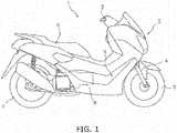
- FIG. 1 is a side view of a straddle-type vehicle 1 on which the engine according to the present embodiment is mounted.
- the straddle-type vehicle 1 according to the present embodiment is a scooter-type vehicle.
- the straddle-type vehicle 1 includes a vehicle body 2, a handle 3, a steering device 4, a front wheel 5, a seat 6, a rear wheel 7, and an engine 8.
- the handle 3 is coupled to the front wheel 5 via the steering device 4.
- the seat 6 is supported on the vehicle body 2.
- a foot board 9 is disposed in front of and below the seat 6.
- the foot board 9 has a planar shape.
- the foot board 9 may have a shape in which the middle portion in the vehicle width direction protrudes upward to form a convex shape.
- the engine 8 is disposed under the seat 6.
- the engine 8 is swingably supported on the vehicle body 2.
- the following describes in detail the structure of the engine 8.
- the up and down, left and right, front and rear directions in the following explanation signify the directions while the engine 8 is mounted on the straddle-type vehicle 1.
- FIG. 2 is a cross-sectional view of the engine 8.
- the engine 8 includes a cylinder head 11, a cylinder 12, a piston 13, a crankcase 14, and a crankshaft 15.
- a cam shaft 44 is disposed inside the cylinder head 11.
- a first cam chain sprocket 45 is connected to the cam shaft 44.
- the cylinder head 11 is connected to the cylinder 12.
- the cylinder 12 is connected to the crankcase 14.
- the piston 13 is disposed inside the cylinder 12.
- the crankshaft 15 is coupled to the piston 13 via a connecting rod 16.
- the crankshaft 15 is housed in the crankcase 14 and rotates around an axis Ax1 of the crankshaft 15.
- the "axial direction” signifies the direction in which the axis Ax1 of the crankshaft 15 extends.
- the crankshaft 15 includes a first shaft portion 151, a second shaft portion 152, and crank webs 153a and 153b.
- the crank webs 153a and 153b are positioned between the first shaft portion 151 and the second shaft portion 152 and are disposed inside the crankcase 14.
- the crank webs 153a and 153b extend in the radial direction.
- the crank webs 153a and 153b are disposed with a gap therebetween in the axial direction.
- the crank webs 153a and 153b communicate with each other with a crank pin 154 connected to the connecting rod 16.
- the first shaft portion 151 extends one way in the axial direction from the inside of the crankcase 14 toward the outside.
- the first shaft portion 151 extends one way in the axial direction from the crank web 153a.
- the first shaft portion 151 protrudes one way in the axial direction from the crankcase 14.
- the second shaft portion 152 extends in the other way in the axial direction from the inside of the crankcase 14 toward the outside.
- the second shaft portion 152 extends in the other way in the axial direction from the crank web 153b.
- the second shaft portion 152 protrudes the other way in the axial direction from the crankcase 14.
- the second shaft portion 152 is coupled to a drive pulley 171 of a transmission 17.
- a second cam chain sprocket 46 is connected to the second shaft portion 152.
- a cam chain 47 is wound on the first cam chain sprocket 45 and the second cam chain sprocket 46.
- a cam chain chamber 48 is provided in the cylinder head 11, the cylinder 12, and the crankcase 14, and the cam chain 47 is disposed inside the cam chain chamber 48.
- the crankcase 14 includes a crankcase body 20 and an oil pump cover 23.
- the crankcase body 20 includes a first split body 20a on the first shaft portion 151 side and a second split body 20b on the second shaft portion 152 side.
- the first split body 20a and the second split body 20b are separate from each other.
- a joining surface M1 of the first split body 20a and the second split body 20b extends along a flat surface perpendicular to the axis Ax1 of the crankshaft.
- the first split body 20a includes a first side wall 141 and a cover portion 142.
- the first side wall 141 covers the crank web 153a in the axial direction.
- the first side wall 141 overlaps the crank web 153a as seen in the axial direction.
- the first side wall 141 is formed integrally with the first split body 20a. In other words, the first side wall 141 is formed continuously with the first split body 20a.
- the first side wall 141 is a portion without a joint seam.
- the first side wall 141 includes a first opening 143.
- the first shaft portion 151 of the crankshaft 15 passes through the first opening 143.
- the first shaft portion 151 protrudes from the first opening 143.
- the cover portion 142 protrudes in the axial direction from the first side wall 141.
- the cover portion 142 extends in the circumferential direction of the axis Ax1 of the crankshaft 15.
- the cover portion 142 is disposed in a position further away in the radial direction from the axis Ax1 than a rotor 24 of a generator with motor function 19.
- the second split body 20b includes a second side wall 144.
- the second side wall 144 adjoins the cam chain chamber 48.
- the second side wall 144 is disposed between the cam chain chamber 48 and the transmission 17.
- the second side wall 144 includes an opening portion 145.
- the second shaft portion 152 is disposed in the opening portion 145.
- the oil pump cover 23 is a separate body from the crankcase body 20.
- the oil pump cover 23 is attached to the second side wall 144.
- the oil pump cover 23 closes the opening portion 145 of the second side wall 144.
- the oil pump cover 23 includes a second opening 231.
- the second shaft portion 152 passes through the second opening 231.
- the second shaft portion 152 protrudes from the second opening 231.
- the engine 8 includes a cooling fan 18 and the generator with motor function 19.
- the cooling fan 18 is attached to the first shaft portion 151 of the crankshaft 15.
- the generator with motor function 19 is disposed between the crankcase 14 and the cooling fan 18.
- the engine 8 includes a radiator 21.
- the radiator 21 is disposed outside of the cooling fan 18 in the axial direction.
- FIG. 3 is an enlarged cross-sectional view around the generator with motor function 19 and the cooling fan 18.
- the cooling fan 18 is disposed coaxially with the crankshaft 15.
- the cooling fan 18 is a centrifugal fan for blowing air in the centrifugal direction.
- the cooling fan 18 includes a disk-shaped fan body 181 and a plurality of vane portions 182.
- the plurality of vane portions 182 are disposed on the fan body 181.
- the cooling fan 18 is fixed to the belowmentioned rotor 24 of the generator with motor function 19 with a bolt 29.
- the engine 8 includes a housing member 22.
- the housing member 22 is attached to the cover portion 142 of the crankcase 14.
- the housing member 22 overlaps the crankcase 14 as seen from the axial direction.
- the generator with motor function 19 and the cooling fan 18 are disposed inside a housing space configured by the cover portion 142 of the crankcase 14 and the housing member 22.
- the generator with motor function 19 is connected to an electrical circuit which is not included in the drawings.
- the generator with motor function 19 receives electrical power supplied by the electric circuit thereby functioning as a motor.
- the generator with motor function 19 functions as a starter motor for starting the engine 8.
- the generator with motor function 19 may function as an assist motor for supplementing the driving power for the engine 8.
- the generator with motor function 19 is able to function as a generator.
- the generator with motor function 19 supplies electrical power to the electric circuit when functioning as the generator.
- the generator with motor function 19 includes the rotor 24, a stator 25, and a sensor unit 26.
- the rotor 24 is fixed to the first shaft portion 151 of the crankshaft 15 and rotates with the crankshaft 15.
- the rotor 24 includes a rotor core 27 and a permanent magnet 28.
- the rotor core 27 has a cylindrical shape and opens toward the crankcase 14.
- the permanent magnet 28 is attached to the inner circumferential surface of the rotor core 27.
- a through-hole 271 is provided in the rotor core 27 to allow for the passage of air. The through-hole 271 penetrates the rotor core 27 in the axial direction.
- FIG. 4 is a view of the stator 25 as seen in the direction facing the second shaft portion 152 from the first shaft portion 151 of the crankshaft 15.
- FIG. 5 is a view of the stator 25 as seen in the direction facing the first shaft portion 151 from the second shaft portion 152 of the crankshaft 15.
- the stator 25 includes a stator core 31 and a plurality of teeth 32. In the drawings, only a portion of the plurality of teeth 32 are provided with the reference numeral 32.
- the stator core 31 includes an opening 311 which the first shaft portion 151 of the crankshaft 15 passes therethrough.
- the plurality of teeth 32 extend in the radial direction from the stator core 31.
- the plurality of teeth 32 are disposed in the circumferential direction with gaps therebetween.
- the stator 25 includes a stator coil 33.
- the stator coil 33 is wound onto the plurality of teeth 32.
- a coil cable 35 is connected to the stator coil 33.
- the stator 25 is fixed directly to the first side wall 141 of the crankcase 14 with bolts 34. Specifically, the stator 25 is fixed directly to a protruding portion 146 of the first side wall 141.
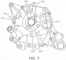
- FIG. 6 is a view of a first side wall 141 of the crankcase 14, the stator 25, and the sensor unit 26 as seen from the axial direction.
- FIG. 7 is a view of the first side wall 141 of the crankcase 14 as seen from the axial direction.
- the protruding portion 146 is provided around the first opening 143 and protrudes in the axial direction.
- the stator core 31 includes a plurality of holes 312.
- a plurality of holes 147 are provided in the protruding portion 146.
- the plurality of holes 147 of the protruding portion 146 are disposed in correspondence to the plurality of holes 312 of the stator core 31.
- the stator 25 is fixed to the protruding portion 146 by the bolts 34 that pass through the holes 312 of the stator core 31 and the holes 147 of the protruding portion 146.
- the first side wall 141 includes a recessed portion 148.
- the recessed portion 148 is provided around the first opening 143 and is disposed inside the protruding portion 146.
- the recessed portion 148 has a shape that is recessed from the outer surface of the crankcase 14 toward the inside of the crankcase 14.
- An oil seal 42 is attached to the recessed portion 148. The oil seal 42 seals the space between the crankcase 14 and the crankshaft 15.
- the sensor unit 26 is attached to the stator 25. As illustrated in FIG. 4 , the sensor unit 26 includes a plurality of sensors 36-39 and a coupling portion 40.
- the plurality of sensors 36-39 include a first sensor 36, a second sensor 37, a third sensor 38, and a fourth sensor 39.
- the first to fourth sensors 36-39 are disposed in the gaps between the teeth 32 of the stator 25.
- the first to fourth sensors 36-39 are magnetic sensors.
- the first to fourth sensors 36-39 are Hall sensors.
- the first sensor 36 detects the absolute position of the rotor 24 by detecting changes in the magnetic flux of the permanent magnet 28 caused by the rotation of the rotor 24.
- the second to fourth sensors 37-39 detect the phase of the rotor 24 by detecting changes in the magnetic flux of the permanent magnet 28 caused by the rotation of the rotor 24.
- the coupling portion 40 couples the first to fourth sensors 36-39.
- the coupling portion 40 is connected to the first to fourth sensors 36-39.
- a sensor cable 41 is connected to the sensor unit 26.
- the coil cable 35 and the sensor cable 41 are bundled together with a bracket 43.
- the bracket 43 is attached to the stator core 31.
- the sensor unit 26 is disposed facing the first side wall 141 of the crankcase 14.
- the coupling portion 40 faces the crankcase 14.
- the coupling portion 40 is disposed between the stator 25 and the first side wall 141 of the crankcase 14.
- the engine 8 includes an oil pump 49.
- the oil pump 49 is disposed in the housing space inside the second split body 20b.
- the housing space is communicated with the opening portion 145 of the second side wall 144.
- the oil pump cover 23 covers the oil pump 49.
- the oil pump cover 23 overlaps the oil pump 49 as seen in the axial direction.
- the oil pump 49 is connected to the second shaft portion 152.
- the oil pump 49 includes a first pump gear 51 and a pump body 52.
- the first pump gear 51 is connected to the second shaft portion 152.
- the first pump gear 51 is disposed in alignment with the second cam chain sprocket 46 in the axial direction.
- the first pump gear 51 is attached on the outer circumferential surface of the second shaft portion 152.
- the first pump gear 51 rotates integrally with the second shaft portion 152 around the axis.
- the pump body 52 is aligned with the cam chain 47 in the radial direction of the cam chain sprocket 46. That is, the pump body 52 overlaps the cam chain 47 as seen in the radial direction of the second cam chain sprocket 46.
- the pump body 52 is connected to the first pump gear 51.
- a second pump gear 54 is attached to an input shaft 53 of the pump body 52. The second pump gear 54 meshes with the first pump gear 51.
- the stator 25 of the generator with motor function 19 is fixed to the first side wall 141 of the crankcase body 20 in the engine 8 according to the present embodiment as discussed above.
- the stiffness of the first side wall 141 is greater than the stiffness of the oil pump cover 23.
- at least a portion of the first side wall 141 is thicker than the oil pump cover 23.
- the first side wall 141 is formed integrally with the first split body 20a. Therefore, magnetic sound from the generator with motor function 19 can be kept at a low level by fixing the stator 25 directly to the first side wall 141 having high stiffness.
- the oil pump 49 is connected to the second shaft portion 152 instead of the first shaft portion 151 to which the rotor 24 is attached.
- an attachment portion of the generator with motor function 19 to the first shaft portion 151 can be easily assured in comparison to when the oil pump 49 is provided on the first shaft portion 151.
- the generator with motor function 19 is relatively larger in size than the conventional generator and therefore the ability to assure the attachment portion is effective in order to improve the layout ability.
- stator 25 when the stator 25 is attached to the oil pump cover 23, there is a problem in that the tolerance for assembling the oil pump cover 23 effects the attachment precision of the stator 25.
- the stator 25 of the present embodiment is fixed directly to the first side wall 141 of the crankcase 14. As a result, the assembly precision of the stator 25 can be improved.
- the cam chain 47 is disposed on the opposite side with respect to the generator with motor function 19.
- the freedom of design of the first wall side 141 is improved and the stiffness of the first side wall 141 can be assured easily.
- the housing space for the generator with motor function 19 can be assured more easily.
- the pump body 52 is aligned with the cam chain 47 in the radial direction of the cam chain sprocket 46. As a result, the pump body 52 can be disposed in a compact manner.
- the cooling fan 18 is adjacent to the generator with motor function 19 in the axial direction. As a result, cooling of the generator with motor function 19 by the cooling fan 18 can be carried out effectively. Furthermore, while the calorific content of the generator with motor function 19 is greater than that of a conventional generator, a large space for heat dissipation can be easily assured by using the space in which the cooling fan 18 is disposed.
- the sensor unit 26 is fixed to the stator 25.
- the propagation of heat from the crankcase 14 toward the sensor unit 26 can be suppressed in comparison to when the sensor unit 26 is attached to the crankcase 14.
- the effect of heat on the sensor unit 26 can be suppressed.
- the sensors 36-39 of the sensor unit 26 are Hall sensors with low heat resistance, and therefore the effect of suppressing the propagation of heat from the crankcase 14 toward the sensor unit 26 becomes more effective.
- the oil seal 42 is attached to the recessed portion 148 that is recessed from the outer surface of the first side wall 141. As a result, the oil seal 42 can be attached and detached easily from the outside of the crankcase 14. Consequently, the maintenance performance of the engine 8 can be improved.
- the straddle-type vehicle is not limited to a scooter-type vehicle and may be a moped or a sports type vehicle.
- the straddle-type vehicle is not limited to a motorcycle and may be an all-terrain vehicle or a snowmobile.
- the structure inside the engine 8 may be changed.
- the disposition of the cooling fan 18 may be changed.
- the disposition of the cam chain 47 may be changed.
- the disposition of the transmission 17 may be changed.
- the disposition of the oil pump 49 may be changed.
- the structure of the first side wall 141 may be changed.
- the protruding portion 146 may be omitted.
- the recessed portion 148 of the protruding portion 146 may be omitted.
- the position of the joining surface M1 between the first split body 20a and the second split body 20b of the crankcase 14 may be changed.
- the structure of the sensor unit 26 is not limited to the structure of the above embodiment and may be changed.
- the number of sensors is not limited to four and the number may be two, three, or five or more.
- the sensors may be a sensor type other than a Hall sensor.
- the coupling portion 40 may be omitted.
- the disposition of the sensors may be changed.
- the disposition of the sensor unit 26 may be changed.
Abstract
Description
- The present invention relates to an engine, and in particular to an engine for a straddle-type vehicle.
- An engine for a straddle-type vehicle generally drives a generator and an oil pump with rotational power from a crankshaft. For example, a rotor of the generator is fixed to the right axial end of the crankshaft in the engine in
JP 2014 240628 A - A drive gear of the oil pump is provided on right shaft portion of the crankshaft. An opening for allowing access to the oil pump is formed on the right side wall of the crankcase. The opening is closed by an oil pump cover. The oil pump cover is detachably attached to the crankcase with a fixing member such as a bolt. Moreover, a stator of the abovementioned generator is fixed to the oil pump cover with a fixing member such as a bolt.
- Recently, a generator with motor function has been installed in an engine for a straddle-type vehicle in place of the conventional generator. A generator with motor function is expected to provide a larger volume of generated electricity or a larger motor torque than the conventional generator. There is a problem in that the magnetic sound generated when driving the generator with motor function also increases if the volume of generated electricity or the motor torque is increased.
- The magnetic sound is amplified by minute vibrations in the structure around the generator with motor function. Therefore, in order to reduce the magnetic sound in the abovementioned engine in
JP 2014 240628 A - Moreover, when the thickness of the oil pump cover is increased in order to increase the stiffness of the oil pump cover, or if the number of bolts for fixing the oil pump cover is increased, there is a problem that the housing space for the generator with motor function will need to be made narrower. Alternatively, there will be a need to consider the positional relationship between the bolts (bolt seats) and the generator with motor function. In particular, there is a concern that the layout for the generator with motor function may be restricted because the generator with motor function is larger than a conventional generator.
- It is an object of the present invention is to reduce the magnetic sound and improve the layout ability of the generator with motor function while suppressing an increase in the weight of the engine for an engine having a generator with motor function mounted therein. According to the present invention said object is solved by an engine having features of independent claim 1. Preferred embodiments are laid down in the dependent claims.
- An engine according to a first aspect of the present invention includes a crankcase, a crankshaft, a generator with motor function, and an oil pump. At least a portion of the crankshaft is housed in the crankcase. The crankshaft rotates around an axis. The generator with motor function includes a rotor and a stator. The rotor is fixed to the crankshaft. The stator is fixed to the crankcase while the crankshaft is passing through the stator. The oil pump is housed in the crankcase and is connected to the crankshaft. The crankshaft includes a first shaft portion and a second shaft portion. The first shaft portion extends one way in the axial direction from the inside of the crankcase toward the outside, and is fixed to the rotor. The second shaft portion extends the other way in the axial direction from the inside of the crankcase toward the outside, and is connected to the oil pump. The crankcase includes a crankcase body and an oil pump cover. The crankcase body includes a first side wall and a second side wall. The first shaft portion is passing through the first side wall. The second shaft portion is disposed in the second side wall. The second side wall includes an opening portion that is communicated with a housing space for the oil pump. The oil pump cover closes the opening portion of the second side wall. The second shaft portion is passing through the oil pump cover. The stator is fixed to the first side wall of the crankcase body.
- The stator of the generator with motor function is fixed to the first side wall of the crankcase body. Because the first side wall of the crankcase body is generally a portion of the component for housing the crankshaft, the stiffness of the first side wall is assured in comparison to the oil pump cover. For example, the first side wall of the crankcase body is larger or is thicker than the oil pump cover. As a result, magnetic sound can be limited to a smaller amount in comparison to when the stator is fixed to the oil pump cover.
- If the stator was hypothetically fixed to the oil pump cover, the thickness of the oil pump cover would need to be increased or the number of bolts for fixing the oil pump cover would need to be increased in order to limit the amount of the magnetic sound. In comparison to the above, the amount of the magnetic sound can be limited by fixing the stator to the first wall side of the crankcase body in the present invention. Consequently, an increase in the weight of the engine can be suppressed while suppressing the magnetic sound.
- Furthermore, the oil pump is provided on the second shaft portion instead of the first shaft portion on which the rotor of the generator with motor function is provided. As a result, an attachment portion of the generator with motor function to the first shaft portion can be more easily assured in comparison to when the oil pump is provided on the first shaft portion. In particular, the generator with motor function is relatively larger in size than the conventional generator and therefore the ability to assure the attachment portion is more effective with respect to improving the layout ability.
- The engine may further include a cam chain sprocket and a cam chain. The cam chain sprocket may be connected to the second shaft portion. The cam chain may be wound around the cam chain sprocket. In this case, the cam chain is disposed on the opposite side with respect to the generator with motor function. As a result, the freedom of design of the first wall side is improved and the stiffness can be assured easily. Moreover, the housing space for the generator with motor function can be assured more easily.
- The oil pump may include a pump gear and a pump body. The pump gear may be connected to the second shaft portion. The pump body may be connected to the pump gear. The pump body may be aligned with the cam chain in the radial direction of the cam chain sprocket. In this case, the pump body can be disposed in a compact manner.
- The engine may further include a cooling fan connected to the first shaft portion. In this case, the generator with motor function can be cooled more effectively because the cooling fan is disposed near the generator with motor function. Furthermore, while the calorific content of the generator with motor function is greater than that of a conventional generator, a large space for heat dissipation can be easily assured by using the space in which the cooling fan is disposed.
- The engine may further include a sensor for detecting the phase of the crankshaft. The sensor may be fixed to the stator. In this case, the propagation of heat from the crankcase toward the sensor can be suppressed in comparison to when the sensor is attached to the crankcase. As a result, the effect of heat on the sensor can be suppressed.
- The sensor may be a Hall sensor. In this case, the propagation of the heat from the crankcase on the sensor can be more effectively suppressed because the heat resistance of a Hall sensor is low.
- The crankcase may include a first opening and a protruding portion. The first shaft portion may protrude from the first opening. The protruding portion may be provided around the first opening and may protrude in the axial direction. The stator may be fixed directly to the protruding portion. In this case, the stator can be fixed directly to the crankcase with a simple structure.
- The engine may further include an oil seal for providing a seal between the crankcase and the crankshaft. The crankcase may include a recessed portion provided around the first opening and recessed from the outer surface of the crankcase. The oil seal may be attached to the recessed portion. In this case, the oil seal can be attached and detached easily from the outside of the crankcase. Consequently, the maintenance performance of the engine can be improved.
- The crankcase may further include a first split body on the first shaft portion side and a second split body on the second shaft portion side. The first split body and the second split body may be separate from each other. In this case, the provision of a joint seam due to the division of the first side wall may be avoided. Consequently, the stiffness of the first side wall can be further assured.
- The crankshaft may include a crank web which extends in the radial direction. The first shaft portion may extend one way in the axial direction from the crank web. The second shaft portion may extend the other way in the axial direction from the crank web.
-
FIG. 1 is a side view of the straddle-type vehicle according to an embodiment. -
FIG. 2 is a cross-sectional view of an engine according to an embodiment. -
FIG. 3 is an enlarged cross-sectional view around a generator with motor function and a cooling fan. -
FIG. 4 is a view of a stator as seen from the axial direction of the crankshaft. -
FIG. 5 is a view of the stator as seen from the axial direction of the crankshaft. -
FIG. 6 is a view of a first side wall of the crankcase, the stator, and a sensor unit as seen from the axial direction. -
FIG. 7 is a view of the first side wall of the crankcase as seen from the axial direction. - The following is a description of an engine according to the present embodiment with reference to the drawings.
FIG. 1 is a side view of a straddle-type vehicle 1 on which the engine according to the present embodiment is mounted. The straddle-type vehicle 1 according to the present embodiment is a scooter-type vehicle. As illustrated inFIG. 1 , the straddle-type vehicle 1 includes avehicle body 2, ahandle 3, asteering device 4, afront wheel 5, aseat 6, a rear wheel 7, and anengine 8. - The
handle 3 is coupled to thefront wheel 5 via thesteering device 4. Theseat 6 is supported on thevehicle body 2. A foot board 9 is disposed in front of and below theseat 6. The foot board 9 has a planar shape. The foot board 9 may have a shape in which the middle portion in the vehicle width direction protrudes upward to form a convex shape. - The
engine 8 is disposed under theseat 6. Theengine 8 is swingably supported on thevehicle body 2. The following describes in detail the structure of theengine 8. The up and down, left and right, front and rear directions in the following explanation signify the directions while theengine 8 is mounted on the straddle-type vehicle 1. -
FIG. 2 is a cross-sectional view of theengine 8. As illustrated inFIG. 2 , theengine 8 includes a cylinder head 11, a cylinder 12, apiston 13, acrankcase 14, and acrankshaft 15. Acam shaft 44 is disposed inside the cylinder head 11. A firstcam chain sprocket 45 is connected to thecam shaft 44. - The cylinder head 11 is connected to the cylinder 12. The cylinder 12 is connected to the
crankcase 14. Thepiston 13 is disposed inside the cylinder 12. Thecrankshaft 15 is coupled to thepiston 13 via a connectingrod 16. Thecrankshaft 15 is housed in thecrankcase 14 and rotates around an axis Ax1 of thecrankshaft 15. In the following explanation, the "axial direction" signifies the direction in which the axis Ax1 of thecrankshaft 15 extends. - The
crankshaft 15 includes afirst shaft portion 151, asecond shaft portion 152, and crankwebs webs first shaft portion 151 and thesecond shaft portion 152 and are disposed inside thecrankcase 14. The crankwebs webs webs crank pin 154 connected to the connectingrod 16. - The
first shaft portion 151 extends one way in the axial direction from the inside of thecrankcase 14 toward the outside. Thefirst shaft portion 151 extends one way in the axial direction from thecrank web 153a. Thefirst shaft portion 151 protrudes one way in the axial direction from thecrankcase 14. Thesecond shaft portion 152 extends in the other way in the axial direction from the inside of thecrankcase 14 toward the outside. Thesecond shaft portion 152 extends in the other way in the axial direction from thecrank web 153b. Thesecond shaft portion 152 protrudes the other way in the axial direction from thecrankcase 14. Thesecond shaft portion 152 is coupled to a drivepulley 171 of atransmission 17. - A second
cam chain sprocket 46 is connected to thesecond shaft portion 152. Acam chain 47 is wound on the firstcam chain sprocket 45 and the secondcam chain sprocket 46. Acam chain chamber 48 is provided in the cylinder head 11, the cylinder 12, and thecrankcase 14, and thecam chain 47 is disposed inside thecam chain chamber 48. - The
crankcase 14 includes a crankcase body 20 and anoil pump cover 23. The crankcase body 20 includes afirst split body 20a on thefirst shaft portion 151 side and asecond split body 20b on thesecond shaft portion 152 side. Thefirst split body 20a and thesecond split body 20b are separate from each other. A joining surface M1 of thefirst split body 20a and thesecond split body 20b extends along a flat surface perpendicular to the axis Ax1 of the crankshaft. - The
first split body 20a includes afirst side wall 141 and acover portion 142. Thefirst side wall 141 covers thecrank web 153a in the axial direction. Thefirst side wall 141 overlaps thecrank web 153a as seen in the axial direction. Thefirst side wall 141 is formed integrally with thefirst split body 20a. In other words, thefirst side wall 141 is formed continuously with thefirst split body 20a. Thefirst side wall 141 is a portion without a joint seam. - The
first side wall 141 includes afirst opening 143. Thefirst shaft portion 151 of thecrankshaft 15 passes through thefirst opening 143. Thefirst shaft portion 151 protrudes from thefirst opening 143. Thecover portion 142 protrudes in the axial direction from thefirst side wall 141. Thecover portion 142 extends in the circumferential direction of the axis Ax1 of thecrankshaft 15. Thecover portion 142 is disposed in a position further away in the radial direction from the axis Ax1 than a rotor 24 of a generator withmotor function 19. - The
second split body 20b includes asecond side wall 144. Thesecond side wall 144 adjoins thecam chain chamber 48. Thesecond side wall 144 is disposed between thecam chain chamber 48 and thetransmission 17. Thesecond side wall 144 includes anopening portion 145. Thesecond shaft portion 152 is disposed in theopening portion 145. - The
oil pump cover 23 is a separate body from the crankcase body 20. Theoil pump cover 23 is attached to thesecond side wall 144. Theoil pump cover 23 closes theopening portion 145 of thesecond side wall 144. Theoil pump cover 23 includes asecond opening 231. Thesecond shaft portion 152 passes through thesecond opening 231. Thesecond shaft portion 152 protrudes from thesecond opening 231. - The
engine 8 includes a coolingfan 18 and the generator withmotor function 19. The coolingfan 18 is attached to thefirst shaft portion 151 of thecrankshaft 15. The generator withmotor function 19 is disposed between thecrankcase 14 and the coolingfan 18. Theengine 8 includes aradiator 21. Theradiator 21 is disposed outside of the coolingfan 18 in the axial direction. -
FIG. 3 is an enlarged cross-sectional view around the generator withmotor function 19 and the coolingfan 18. As illustrated inFIG. 3 , the coolingfan 18 is disposed coaxially with thecrankshaft 15. The coolingfan 18 is a centrifugal fan for blowing air in the centrifugal direction. The coolingfan 18 includes a disk-shapedfan body 181 and a plurality ofvane portions 182. The plurality ofvane portions 182 are disposed on thefan body 181. The coolingfan 18 is fixed to the belowmentioned rotor 24 of the generator withmotor function 19 with abolt 29. - The
engine 8 includes ahousing member 22. Thehousing member 22 is attached to thecover portion 142 of thecrankcase 14. Thehousing member 22 overlaps thecrankcase 14 as seen from the axial direction. The generator withmotor function 19 and the coolingfan 18 are disposed inside a housing space configured by thecover portion 142 of thecrankcase 14 and thehousing member 22. - The generator with
motor function 19 is connected to an electrical circuit which is not included in the drawings. The generator withmotor function 19 receives electrical power supplied by the electric circuit thereby functioning as a motor. The generator withmotor function 19 functions as a starter motor for starting theengine 8. The generator withmotor function 19 may function as an assist motor for supplementing the driving power for theengine 8. Moreover, the generator withmotor function 19 is able to function as a generator. The generator withmotor function 19 supplies electrical power to the electric circuit when functioning as the generator. - The generator with
motor function 19 includes the rotor 24, astator 25, and asensor unit 26. The rotor 24 is fixed to thefirst shaft portion 151 of thecrankshaft 15 and rotates with thecrankshaft 15. The rotor 24 includes a rotor core 27 and apermanent magnet 28. The rotor core 27 has a cylindrical shape and opens toward thecrankcase 14. Thepermanent magnet 28 is attached to the inner circumferential surface of the rotor core 27. Moreover, a through-hole 271 is provided in the rotor core 27 to allow for the passage of air. The through-hole 271 penetrates the rotor core 27 in the axial direction. - The
stator 25 is fixed to thecrankcase 14 and faces the rotor 24.FIG. 4 is a view of thestator 25 as seen in the direction facing thesecond shaft portion 152 from thefirst shaft portion 151 of thecrankshaft 15.FIG. 5 is a view of thestator 25 as seen in the direction facing thefirst shaft portion 151 from thesecond shaft portion 152 of thecrankshaft 15. As illustrated inFIGS. 4 and5 , thestator 25 includes astator core 31 and a plurality ofteeth 32. In the drawings, only a portion of the plurality ofteeth 32 are provided with thereference numeral 32. - The
stator core 31 includes anopening 311 which thefirst shaft portion 151 of thecrankshaft 15 passes therethrough. The plurality ofteeth 32 extend in the radial direction from thestator core 31. The plurality ofteeth 32 are disposed in the circumferential direction with gaps therebetween. - As illustrated in
FIG. 3 , thestator 25 includes astator coil 33. Thestator coil 33 is wound onto the plurality ofteeth 32. As illustrated inFIG. 5 , acoil cable 35 is connected to thestator coil 33. - The
stator 25 is fixed directly to thefirst side wall 141 of thecrankcase 14 withbolts 34. Specifically, thestator 25 is fixed directly to a protrudingportion 146 of thefirst side wall 141.FIG. 6 is a view of afirst side wall 141 of thecrankcase 14, thestator 25, and thesensor unit 26 as seen from the axial direction.FIG. 7 is a view of thefirst side wall 141 of thecrankcase 14 as seen from the axial direction. - As illustrated in
FIGS. 3 and7 , the protrudingportion 146 is provided around thefirst opening 143 and protrudes in the axial direction. As illustrated inFIG. 4 , thestator core 31 includes a plurality ofholes 312. As illustrated inFIG. 7 , a plurality ofholes 147 are provided in the protrudingportion 146. The plurality ofholes 147 of the protrudingportion 146 are disposed in correspondence to the plurality ofholes 312 of thestator core 31. Thestator 25 is fixed to the protrudingportion 146 by thebolts 34 that pass through theholes 312 of thestator core 31 and theholes 147 of the protrudingportion 146. - As illustrated in
FIG. 3 , thefirst side wall 141 includes a recessed portion 148. The recessed portion 148 is provided around thefirst opening 143 and is disposed inside the protrudingportion 146. The recessed portion 148 has a shape that is recessed from the outer surface of thecrankcase 14 toward the inside of thecrankcase 14. Anoil seal 42 is attached to the recessed portion 148. Theoil seal 42 seals the space between thecrankcase 14 and thecrankshaft 15. - The
sensor unit 26 is attached to thestator 25. As illustrated inFIG. 4 , thesensor unit 26 includes a plurality of sensors 36-39 and acoupling portion 40. The plurality of sensors 36-39 include afirst sensor 36, asecond sensor 37, athird sensor 38, and afourth sensor 39. The first to fourth sensors 36-39 are disposed in the gaps between theteeth 32 of thestator 25. - The first to fourth sensors 36-39 are magnetic sensors. For example, the first to fourth sensors 36-39 are Hall sensors. The
first sensor 36 detects the absolute position of the rotor 24 by detecting changes in the magnetic flux of thepermanent magnet 28 caused by the rotation of the rotor 24. The second to fourth sensors 37-39 detect the phase of the rotor 24 by detecting changes in the magnetic flux of thepermanent magnet 28 caused by the rotation of the rotor 24. - The
coupling portion 40 couples the first to fourth sensors 36-39. Thecoupling portion 40 is connected to the first to fourth sensors 36-39. As illustrated inFIG. 5 , asensor cable 41 is connected to thesensor unit 26. Thecoil cable 35 and thesensor cable 41 are bundled together with abracket 43. Thebracket 43 is attached to thestator core 31. - As illustrated in
FIG. 3 , thesensor unit 26 is disposed facing thefirst side wall 141 of thecrankcase 14. Thecoupling portion 40 faces thecrankcase 14. Thecoupling portion 40 is disposed between thestator 25 and thefirst side wall 141 of thecrankcase 14. - As illustrated in
FIG. 2 , theengine 8 includes anoil pump 49. Theoil pump 49 is disposed in the housing space inside thesecond split body 20b. The housing space is communicated with theopening portion 145 of thesecond side wall 144. Theoil pump cover 23 covers theoil pump 49. Theoil pump cover 23 overlaps theoil pump 49 as seen in the axial direction. - The
oil pump 49 is connected to thesecond shaft portion 152. Specifically, theoil pump 49 includes afirst pump gear 51 and apump body 52. Thefirst pump gear 51 is connected to thesecond shaft portion 152. Thefirst pump gear 51 is disposed in alignment with the secondcam chain sprocket 46 in the axial direction. Thefirst pump gear 51 is attached on the outer circumferential surface of thesecond shaft portion 152. Thefirst pump gear 51 rotates integrally with thesecond shaft portion 152 around the axis. - The
pump body 52 is aligned with thecam chain 47 in the radial direction of thecam chain sprocket 46. That is, thepump body 52 overlaps thecam chain 47 as seen in the radial direction of the secondcam chain sprocket 46. Thepump body 52 is connected to thefirst pump gear 51. Asecond pump gear 54 is attached to aninput shaft 53 of thepump body 52. Thesecond pump gear 54 meshes with thefirst pump gear 51. - The
stator 25 of the generator withmotor function 19 is fixed to thefirst side wall 141 of the crankcase body 20 in theengine 8 according to the present embodiment as discussed above. The stiffness of thefirst side wall 141 is greater than the stiffness of theoil pump cover 23. For example, at least a portion of thefirst side wall 141 is thicker than theoil pump cover 23. Moreover, thefirst side wall 141 is formed integrally with thefirst split body 20a. Therefore, magnetic sound from the generator withmotor function 19 can be kept at a low level by fixing thestator 25 directly to thefirst side wall 141 having high stiffness. - In comparison to when the
stator 25 is fixed to theoil pump cover 23, there is no need to increase the thickness of theoil pump cover 23 or increase the number of bolts for fixing theoil pump cover 23 in order to keep the level of the magnetic sound at a low level. Consequently, an increase in the weight of theengine 8 can be suppressed. - The
oil pump 49 is connected to thesecond shaft portion 152 instead of thefirst shaft portion 151 to which the rotor 24 is attached. As a result, an attachment portion of the generator withmotor function 19 to thefirst shaft portion 151 can be easily assured in comparison to when theoil pump 49 is provided on thefirst shaft portion 151. The generator withmotor function 19 is relatively larger in size than the conventional generator and therefore the ability to assure the attachment portion is effective in order to improve the layout ability. - Moreover, when the
stator 25 is attached to theoil pump cover 23, there is a problem in that the tolerance for assembling theoil pump cover 23 effects the attachment precision of thestator 25. However, thestator 25 of the present embodiment is fixed directly to thefirst side wall 141 of thecrankcase 14. As a result, the assembly precision of thestator 25 can be improved. - The
cam chain 47 is disposed on the opposite side with respect to the generator withmotor function 19. As a result, the freedom of design of thefirst wall side 141 is improved and the stiffness of thefirst side wall 141 can be assured easily. Moreover, the housing space for the generator withmotor function 19 can be assured more easily. - The
pump body 52 is aligned with thecam chain 47 in the radial direction of thecam chain sprocket 46. As a result, thepump body 52 can be disposed in a compact manner. - The cooling
fan 18 is adjacent to the generator withmotor function 19 in the axial direction. As a result, cooling of the generator withmotor function 19 by the coolingfan 18 can be carried out effectively. Furthermore, while the calorific content of the generator withmotor function 19 is greater than that of a conventional generator, a large space for heat dissipation can be easily assured by using the space in which the coolingfan 18 is disposed. - The
sensor unit 26 is fixed to thestator 25. In this case, the propagation of heat from thecrankcase 14 toward thesensor unit 26 can be suppressed in comparison to when thesensor unit 26 is attached to thecrankcase 14. As a result, the effect of heat on thesensor unit 26 can be suppressed. In particular, the sensors 36-39 of thesensor unit 26 are Hall sensors with low heat resistance, and therefore the effect of suppressing the propagation of heat from thecrankcase 14 toward thesensor unit 26 becomes more effective. - The
oil seal 42 is attached to the recessed portion 148 that is recessed from the outer surface of thefirst side wall 141. As a result, theoil seal 42 can be attached and detached easily from the outside of thecrankcase 14. Consequently, the maintenance performance of theengine 8 can be improved. - Although embodiments of the present invention have been described so far, the present invention is not limited to the above embodiments and various modifications may be made within the scope of the invention.
- The straddle-type vehicle is not limited to a scooter-type vehicle and may be a moped or a sports type vehicle. The straddle-type vehicle is not limited to a motorcycle and may be an all-terrain vehicle or a snowmobile.
- The structure inside the
engine 8 may be changed. For example, the disposition of the coolingfan 18 may be changed. The disposition of thecam chain 47 may be changed. The disposition of thetransmission 17 may be changed. The disposition of theoil pump 49 may be changed. - The structure of the
first side wall 141 may be changed. For example, the protrudingportion 146 may be omitted. The recessed portion 148 of the protrudingportion 146 may be omitted. The position of the joining surface M1 between thefirst split body 20a and thesecond split body 20b of thecrankcase 14 may be changed. - The structure of the
sensor unit 26 is not limited to the structure of the above embodiment and may be changed. For example, the number of sensors is not limited to four and the number may be two, three, or five or more. The sensors may be a sensor type other than a Hall sensor. Thecoupling portion 40 may be omitted. The disposition of the sensors may be changed. The disposition of thesensor unit 26 may be changed. - The wording and expressions used herein are used for explanation and are not to be used for a limited interpretation. Various modifications may be permitted within the scope of the claims of the present invention without the exclusion of any equivalents of the characteristic matter illustrated and presented herein. The present invention is provided in various different forms. The disclosure is to be understood as providing embodiments of the principles of the present invention. The embodiment described herein is to be understood as not limiting the present invention to the preferred embodiments described and/or illustrated herein. The present invention is not limited to the embodiments described herein. The present invention contains all possible embodiments that include equivalent elements, alterations, deletions, combinations, modifications, and/or changes that would be understood by a person skilled in the art on the basis of the disclosure. Limitations of the claims should be interpreted broadly on the basis of the terms used in the claims and are not to be limited to the embodiment described in the present description or during the prosecution of the present application.
Claims (11)
- An engine (8) comprising:a crankcase (14);a crankshaft (15) at least a portion of which is housed in the crankcase (14) and which rotates around an axis (Ax1) of the crankshaft (15);a generator with motor function (19) including a rotor (24) fixed to the crankshaft (15) and a stator (25) fixed to the crankcase (14) while the crankshaft (15) passes through the stator (25); andan oil pump (49) housed in the crankcase (14) and connected to the crankshaft (15), whereinthe crankshaft (15) includes:a first shaft portion (151) extending one way in an axial direction of the crankshaft (15) from an inside of the crankcase (14) toward an outside of the crankcase (14), the first shaft portion (151) being fixed to the rotor (24); anda second shaft portion (152) extending the other way in the axial direction from the inside of the crankcase (14) toward the outside of the crankcase (14), the second shaft portion (152) being connected to the oil pump (49);the crankcase (14) includes:a crankcase body (20) including a first side wall (141) through which the first shaft portion (151) passes, and a second side wall (144) through which the second shaft portion (152) is disposed, the second side wall (144) including an opening portion (145) communicated with a housing space for the oil pump (49); andan oil pump cover (23) through which the second shaft portion (152) passes, the oil pump cover (23) closing the opening portion (145) of the second side wall (144); andthe stator (25) is fixed to the first side wall (141).
- An engine (8) according to claim 1, further comprising:a cam chain sprocket (46) connected to the second shaft portion (152); and a cam chain (47) wound around the cam chain sprocket (46).
- An engine (8) according to claim 2, whereinthe oil pump (49) includesa pump gear (51) connected to the second shaft portion (152) anda pump body (52) connected to the pump gear (51), andthe pump body (52) is aligned with the cam chain (47) in a radial direction of the cam chain sprocket (46).
- An engine (8) according to any one of claims 1 to 3, further comprising:a cooling fan (18) connected to the first shaft portion (151).
- An engine (8) according to any one of claims 1 to 4, further comprising:a sensor (36-39) for detecting a phase of the crankshaft (15), whereinthe sensor (36-39) is fixed to the stator (25).
- An engine (8) according to claim 5, whereinthe sensor (36-39) is a Hall sensor.
- An engine (8) according to any one of claims 1 to 6, whereinthe crankcase (14) includes:a first opening (143) through which the first shaft portion (151) protrudes, anda protruding portion (146) provided around the first opening (143), the protruding portion (146) protruding in the axial direction, andthe stator (25) is fixed directly to the protruding portion (146).
- An engine (8) according to any one of claims 1 to 7, further comprising:an oil seal (42) disposed between the crankcase (14) and the crankshaft (15), whereinthe crankcase (14) includes a recessed portion (148) provided around the first opening (143), the recessed portion (148) being recessed from an outer surface of the crankcase (14), andthe oil seal (42) is attached to the recessed portion (148).
- An engine (8) according to any one of claims 1 to 8, whereinthe crankcase (14) includes:a first split body (20a) on the first shaft portion side anda second split body (20b) on the second shaft portion side, the second split body (20b) being separate from the first split body (20a).
- An engine (8) according to any one of claims 1 to 9, whereinthe crankshaft (15) includes a crank web (153a, 153b) extending in a radial direction of the crankshaft (15), andthe first shaft portion (151) extends one way from the crank web (153a, 153b) in the axial direction.
- An engine (8) according to any one of claims 1 to 10, whereinthe crankshaft (15) includes a crank web (153a, 153b) extending in the radial direction of the crankshaft (15), andthe second shaft portion (152) extends the other way from the crank web (153b) in the axial direction.
Applications Claiming Priority (1)
| Application Number | Priority Date | Filing Date | Title |
|---|---|---|---|
| JP2016206127A JP2018066339A (en) | 2016-10-20 | 2016-10-20 | engine |
Publications (2)
| Publication Number | Publication Date |
|---|---|
| EP3312420A1 true EP3312420A1 (en) | 2018-04-25 |
| EP3312420B1 EP3312420B1 (en) | 2019-04-10 |
Family
ID=57984845
Family Applications (1)
| Application Number | Title | Priority Date | Filing Date |
|---|---|---|---|
| EP17154936.3A Active EP3312420B1 (en) | 2016-10-20 | 2017-02-07 | Engine |
Country Status (3)
| Country | Link |
|---|---|
| EP (1) | EP3312420B1 (en) |
| JP (1) | JP2018066339A (en) |
| TW (1) | TWI644015B (en) |
Cited By (1)
| Publication number | Priority date | Publication date | Assignee | Title |
|---|---|---|---|---|
| CN108539899A (en) * | 2018-06-11 | 2018-09-14 | 重庆嘉木机械有限公司 | Engine distance increasing unit monoblock type case lid |
Citations (5)
| Publication number | Priority date | Publication date | Assignee | Title |
|---|---|---|---|---|
| US20120160208A1 (en) * | 2010-12-28 | 2012-06-28 | Kiyohito Takano | Lubricating oil feeding structure of engine |
| CN102635478A (en) * | 2012-04-16 | 2012-08-15 | 江门市永泰精密机械制造有限公司 | Engine for motorcycle |
| EP2574825A1 (en) * | 2011-05-20 | 2013-04-03 | Yamaha Hatsudoki Kabushiki Kaisha | Engine and saddle-type vehicle |
| JP2014240628A (en) | 2013-06-12 | 2014-12-25 | 本田技研工業株式会社 | Installation structure of piston cooling oil injection device in internal combustion engine |
| EP2963784A1 (en) * | 2013-02-28 | 2016-01-06 | Honda Motor Co., Ltd. | Structure for installing sensor in engine unit |
Family Cites Families (2)
| Publication number | Priority date | Publication date | Assignee | Title |
|---|---|---|---|---|
| JP3750791B2 (en) * | 2000-07-28 | 2006-03-01 | 本田技研工業株式会社 | Engine with torque converter |
| US7377351B2 (en) * | 2003-11-07 | 2008-05-27 | Club Car, Inc. | Power train for a utility vehicle |
-
2016
- 2016-10-20 JP JP2016206127A patent/JP2018066339A/en active Pending
-
2017
- 2017-02-07 EP EP17154936.3A patent/EP3312420B1/en active Active
- 2017-03-23 TW TW106109735A patent/TWI644015B/en active
Patent Citations (5)
| Publication number | Priority date | Publication date | Assignee | Title |
|---|---|---|---|---|
| US20120160208A1 (en) * | 2010-12-28 | 2012-06-28 | Kiyohito Takano | Lubricating oil feeding structure of engine |
| EP2574825A1 (en) * | 2011-05-20 | 2013-04-03 | Yamaha Hatsudoki Kabushiki Kaisha | Engine and saddle-type vehicle |
| CN102635478A (en) * | 2012-04-16 | 2012-08-15 | 江门市永泰精密机械制造有限公司 | Engine for motorcycle |
| EP2963784A1 (en) * | 2013-02-28 | 2016-01-06 | Honda Motor Co., Ltd. | Structure for installing sensor in engine unit |
| JP2014240628A (en) | 2013-06-12 | 2014-12-25 | 本田技研工業株式会社 | Installation structure of piston cooling oil injection device in internal combustion engine |
Cited By (1)
| Publication number | Priority date | Publication date | Assignee | Title |
|---|---|---|---|---|
| CN108539899A (en) * | 2018-06-11 | 2018-09-14 | 重庆嘉木机械有限公司 | Engine distance increasing unit monoblock type case lid |
Also Published As
| Publication number | Publication date |
|---|---|
| TWI644015B (en) | 2018-12-11 |
| EP3312420B1 (en) | 2019-04-10 |
| TW201816259A (en) | 2018-05-01 |
| JP2018066339A (en) | 2018-04-26 |
Similar Documents
| Publication | Publication Date | Title |
|---|---|---|
| US7800277B2 (en) | Engine with attached axial gap type rotating electric machine | |
| JP2001078373A (en) | Propulsion apparatus for vehicle | |
| JP5942035B2 (en) | Engine unit sensor installation structure | |
| EP3312420B1 (en) | Engine | |
| KR100635969B1 (en) | V-belt type continuously variable transmission | |
| JP6160633B2 (en) | Drive device | |
| KR100635968B1 (en) | V-belt type continuously variable transmission | |
| JP2014105626A (en) | Saddle riding type vehicle | |
| JP4825324B2 (en) | Drive device | |
| JP2018168737A (en) | Internal combustion engine | |
| TWI682097B (en) | engine | |
| JP4490993B2 (en) | V-belt type continuously variable transmission and vehicle power unit | |
| JP4146698B2 (en) | Engine cover mounting structure | |
| JP2002087082A (en) | Power transmission structure of motor assist device for vehicle | |
| JP2007225119A (en) | V-belt type continuously variable transmission | |
| ES2940351B2 (en) | VEHICLE TO ASSEMBLE MANUAL TRANSMISSION TYPE | |
| JP2014066180A (en) | Electric pump | |
| JP5927628B2 (en) | Oil pump structure in hybrid vehicle | |
| EP3312409B1 (en) | Engine | |
| JP6855307B2 (en) | Drive device | |
| JP5990479B2 (en) | Engine unit sensor installation structure | |
| JP6808567B2 (en) | Hybrid system | |
| JP2023050021A (en) | ACG cover for internal combustion engine | |
| JP2013091413A (en) | Driving device for hybrid vehicle | |
| JP2012179991A (en) | Vehicle drive device |
Legal Events
| Date | Code | Title | Description |
|---|---|---|---|
| PUAI | Public reference made under article 153(3) epc to a published international application that has entered the european phase |
Free format text: ORIGINAL CODE: 0009012 |
|
| STAA | Information on the status of an ep patent application or granted ep patent |
Free format text: STATUS: REQUEST FOR EXAMINATION WAS MADE |
|
| 17P | Request for examination filed |
Effective date: 20170207 |
|
| AK | Designated contracting states |
Kind code of ref document: A1 Designated state(s): AL AT BE BG CH CY CZ DE DK EE ES FI FR GB GR HR HU IE IS IT LI LT LU LV MC MK MT NL NO PL PT RO RS SE SI SK SM TR |
|
| AX | Request for extension of the european patent |
Extension state: BA ME |
|
| RBV | Designated contracting states (corrected) |
Designated state(s): AL AT BE BG CH CY CZ DE DK EE ES FI FR GB GR HR HU IE IS IT LI LT LU LV MC MK MT NL NO PL PT RO RS SE SI SK SM TR |
|
| RIC1 | Information provided on ipc code assigned before grant |
Ipc: F02F 7/00 20060101ALI20180821BHEP Ipc: F16M 1/021 20060101ALI20180821BHEP Ipc: H02K 29/08 20060101ALI20180821BHEP Ipc: H02K 7/18 20060101ALI20180821BHEP Ipc: H02K 11/215 20160101ALI20180821BHEP Ipc: F04B 1/00 20060101AFI20180821BHEP |
|
| GRAP | Despatch of communication of intention to grant a patent |
Free format text: ORIGINAL CODE: EPIDOSNIGR1 |
|
| STAA | Information on the status of an ep patent application or granted ep patent |
Free format text: STATUS: GRANT OF PATENT IS INTENDED |
|
| INTG | Intention to grant announced |
Effective date: 20181024 |
|
| GRAS | Grant fee paid |
Free format text: ORIGINAL CODE: EPIDOSNIGR3 |
|
| GRAA | (expected) grant |
Free format text: ORIGINAL CODE: 0009210 |
|
| STAA | Information on the status of an ep patent application or granted ep patent |
Free format text: STATUS: THE PATENT HAS BEEN GRANTED |
|
| AK | Designated contracting states |
Kind code of ref document: B1 Designated state(s): AL AT BE BG CH CY CZ DE DK EE ES FI FR GB GR HR HU IE IS IT LI LT LU LV MC MK MT NL NO PL PT RO RS SE SI SK SM TR |
|
| REG | Reference to a national code |
Ref country code: GB Ref legal event code: FG4D |
|
| REG | Reference to a national code |
Ref country code: CH Ref legal event code: EP Ref country code: AT Ref legal event code: REF Ref document number: 1119019 Country of ref document: AT Kind code of ref document: T Effective date: 20190415 |
|
| REG | Reference to a national code |
Ref country code: IE Ref legal event code: FG4D |
|
| REG | Reference to a national code |
Ref country code: DE Ref legal event code: R096 Ref document number: 602017003118 Country of ref document: DE |
|
| REG | Reference to a national code |
Ref country code: NL Ref legal event code: MP Effective date: 20190410 |
|
| REG | Reference to a national code |
Ref country code: LT Ref legal event code: MG4D |
|
| REG | Reference to a national code |
Ref country code: AT Ref legal event code: MK05 Ref document number: 1119019 Country of ref document: AT Kind code of ref document: T Effective date: 20190410 |
|
| PG25 | Lapsed in a contracting state [announced via postgrant information from national office to epo] |
Ref country code: NL Free format text: LAPSE BECAUSE OF FAILURE TO SUBMIT A TRANSLATION OF THE DESCRIPTION OR TO PAY THE FEE WITHIN THE PRESCRIBED TIME-LIMIT Effective date: 20190410 |
|
| PG25 | Lapsed in a contracting state [announced via postgrant information from national office to epo] |
Ref country code: NO Free format text: LAPSE BECAUSE OF FAILURE TO SUBMIT A TRANSLATION OF THE DESCRIPTION OR TO PAY THE FEE WITHIN THE PRESCRIBED TIME-LIMIT Effective date: 20190710 Ref country code: PT Free format text: LAPSE BECAUSE OF FAILURE TO SUBMIT A TRANSLATION OF THE DESCRIPTION OR TO PAY THE FEE WITHIN THE PRESCRIBED TIME-LIMIT Effective date: 20190910 Ref country code: FI Free format text: LAPSE BECAUSE OF FAILURE TO SUBMIT A TRANSLATION OF THE DESCRIPTION OR TO PAY THE FEE WITHIN THE PRESCRIBED TIME-LIMIT Effective date: 20190410 Ref country code: LT Free format text: LAPSE BECAUSE OF FAILURE TO SUBMIT A TRANSLATION OF THE DESCRIPTION OR TO PAY THE FEE WITHIN THE PRESCRIBED TIME-LIMIT Effective date: 20190410 Ref country code: SE Free format text: LAPSE BECAUSE OF FAILURE TO SUBMIT A TRANSLATION OF THE DESCRIPTION OR TO PAY THE FEE WITHIN THE PRESCRIBED TIME-LIMIT Effective date: 20190410 Ref country code: HR Free format text: LAPSE BECAUSE OF FAILURE TO SUBMIT A TRANSLATION OF THE DESCRIPTION OR TO PAY THE FEE WITHIN THE PRESCRIBED TIME-LIMIT Effective date: 20190410 Ref country code: AL Free format text: LAPSE BECAUSE OF FAILURE TO SUBMIT A TRANSLATION OF THE DESCRIPTION OR TO PAY THE FEE WITHIN THE PRESCRIBED TIME-LIMIT Effective date: 20190410 Ref country code: ES Free format text: LAPSE BECAUSE OF FAILURE TO SUBMIT A TRANSLATION OF THE DESCRIPTION OR TO PAY THE FEE WITHIN THE PRESCRIBED TIME-LIMIT Effective date: 20190410 |
|
| PG25 | Lapsed in a contracting state [announced via postgrant information from national office to epo] |
Ref country code: GR Free format text: LAPSE BECAUSE OF FAILURE TO SUBMIT A TRANSLATION OF THE DESCRIPTION OR TO PAY THE FEE WITHIN THE PRESCRIBED TIME-LIMIT Effective date: 20190711 Ref country code: BG Free format text: LAPSE BECAUSE OF FAILURE TO SUBMIT A TRANSLATION OF THE DESCRIPTION OR TO PAY THE FEE WITHIN THE PRESCRIBED TIME-LIMIT Effective date: 20190710 Ref country code: RS Free format text: LAPSE BECAUSE OF FAILURE TO SUBMIT A TRANSLATION OF THE DESCRIPTION OR TO PAY THE FEE WITHIN THE PRESCRIBED TIME-LIMIT Effective date: 20190410 Ref country code: LV Free format text: LAPSE BECAUSE OF FAILURE TO SUBMIT A TRANSLATION OF THE DESCRIPTION OR TO PAY THE FEE WITHIN THE PRESCRIBED TIME-LIMIT Effective date: 20190410 Ref country code: PL Free format text: LAPSE BECAUSE OF FAILURE TO SUBMIT A TRANSLATION OF THE DESCRIPTION OR TO PAY THE FEE WITHIN THE PRESCRIBED TIME-LIMIT Effective date: 20190410 |
|
| PG25 | Lapsed in a contracting state [announced via postgrant information from national office to epo] |
Ref country code: IS Free format text: LAPSE BECAUSE OF FAILURE TO SUBMIT A TRANSLATION OF THE DESCRIPTION OR TO PAY THE FEE WITHIN THE PRESCRIBED TIME-LIMIT Effective date: 20190810 Ref country code: AT Free format text: LAPSE BECAUSE OF FAILURE TO SUBMIT A TRANSLATION OF THE DESCRIPTION OR TO PAY THE FEE WITHIN THE PRESCRIBED TIME-LIMIT Effective date: 20190410 |
|
| REG | Reference to a national code |
Ref country code: DE Ref legal event code: R097 Ref document number: 602017003118 Country of ref document: DE |
|
| PG25 | Lapsed in a contracting state [announced via postgrant information from national office to epo] |
Ref country code: SK Free format text: LAPSE BECAUSE OF FAILURE TO SUBMIT A TRANSLATION OF THE DESCRIPTION OR TO PAY THE FEE WITHIN THE PRESCRIBED TIME-LIMIT Effective date: 20190410 Ref country code: DK Free format text: LAPSE BECAUSE OF FAILURE TO SUBMIT A TRANSLATION OF THE DESCRIPTION OR TO PAY THE FEE WITHIN THE PRESCRIBED TIME-LIMIT Effective date: 20190410 Ref country code: CZ Free format text: LAPSE BECAUSE OF FAILURE TO SUBMIT A TRANSLATION OF THE DESCRIPTION OR TO PAY THE FEE WITHIN THE PRESCRIBED TIME-LIMIT Effective date: 20190410 Ref country code: EE Free format text: LAPSE BECAUSE OF FAILURE TO SUBMIT A TRANSLATION OF THE DESCRIPTION OR TO PAY THE FEE WITHIN THE PRESCRIBED TIME-LIMIT Effective date: 20190410 Ref country code: RO Free format text: LAPSE BECAUSE OF FAILURE TO SUBMIT A TRANSLATION OF THE DESCRIPTION OR TO PAY THE FEE WITHIN THE PRESCRIBED TIME-LIMIT Effective date: 20190410 |
|
| PLBE | No opposition filed within time limit |
Free format text: ORIGINAL CODE: 0009261 |
|
| STAA | Information on the status of an ep patent application or granted ep patent |
Free format text: STATUS: NO OPPOSITION FILED WITHIN TIME LIMIT |
|
| PG25 | Lapsed in a contracting state [announced via postgrant information from national office to epo] |
Ref country code: SM Free format text: LAPSE BECAUSE OF FAILURE TO SUBMIT A TRANSLATION OF THE DESCRIPTION OR TO PAY THE FEE WITHIN THE PRESCRIBED TIME-LIMIT Effective date: 20190410 |
|
| 26N | No opposition filed |
Effective date: 20200113 |
|
| PG25 | Lapsed in a contracting state [announced via postgrant information from national office to epo] |
Ref country code: TR Free format text: LAPSE BECAUSE OF FAILURE TO SUBMIT A TRANSLATION OF THE DESCRIPTION OR TO PAY THE FEE WITHIN THE PRESCRIBED TIME-LIMIT Effective date: 20190410 |
|
| PG25 | Lapsed in a contracting state [announced via postgrant information from national office to epo] |
Ref country code: SI Free format text: LAPSE BECAUSE OF FAILURE TO SUBMIT A TRANSLATION OF THE DESCRIPTION OR TO PAY THE FEE WITHIN THE PRESCRIBED TIME-LIMIT Effective date: 20190410 |
|
| REG | Reference to a national code |
Ref country code: CH Ref legal event code: PL |
|
| REG | Reference to a national code |
Ref country code: BE Ref legal event code: MM Effective date: 20200229 |
|
| PG25 | Lapsed in a contracting state [announced via postgrant information from national office to epo] |
Ref country code: LU Free format text: LAPSE BECAUSE OF NON-PAYMENT OF DUE FEES Effective date: 20200207 Ref country code: MC Free format text: LAPSE BECAUSE OF FAILURE TO SUBMIT A TRANSLATION OF THE DESCRIPTION OR TO PAY THE FEE WITHIN THE PRESCRIBED TIME-LIMIT Effective date: 20190410 |
|
| PG25 | Lapsed in a contracting state [announced via postgrant information from national office to epo] |
Ref country code: LI Free format text: LAPSE BECAUSE OF NON-PAYMENT OF DUE FEES Effective date: 20200229 Ref country code: CH Free format text: LAPSE BECAUSE OF NON-PAYMENT OF DUE FEES Effective date: 20200229 |
|
| PG25 | Lapsed in a contracting state [announced via postgrant information from national office to epo] |
Ref country code: IE Free format text: LAPSE BECAUSE OF NON-PAYMENT OF DUE FEES Effective date: 20200207 |
|
| PG25 | Lapsed in a contracting state [announced via postgrant information from national office to epo] |
Ref country code: BE Free format text: LAPSE BECAUSE OF NON-PAYMENT OF DUE FEES Effective date: 20200229 |
|
| GBPC | Gb: european patent ceased through non-payment of renewal fee |
Effective date: 20210207 |
|
| PG25 | Lapsed in a contracting state [announced via postgrant information from national office to epo] |
Ref country code: GB Free format text: LAPSE BECAUSE OF NON-PAYMENT OF DUE FEES Effective date: 20210207 |
|
| PG25 | Lapsed in a contracting state [announced via postgrant information from national office to epo] |
Ref country code: MT Free format text: LAPSE BECAUSE OF FAILURE TO SUBMIT A TRANSLATION OF THE DESCRIPTION OR TO PAY THE FEE WITHIN THE PRESCRIBED TIME-LIMIT Effective date: 20190410 Ref country code: CY Free format text: LAPSE BECAUSE OF FAILURE TO SUBMIT A TRANSLATION OF THE DESCRIPTION OR TO PAY THE FEE WITHIN THE PRESCRIBED TIME-LIMIT Effective date: 20190410 |
|
| PG25 | Lapsed in a contracting state [announced via postgrant information from national office to epo] |
Ref country code: MK Free format text: LAPSE BECAUSE OF FAILURE TO SUBMIT A TRANSLATION OF THE DESCRIPTION OR TO PAY THE FEE WITHIN THE PRESCRIBED TIME-LIMIT Effective date: 20190410 |
|
| PGFP | Annual fee paid to national office [announced via postgrant information from national office to epo] |
Ref country code: FR Payment date: 20230221 Year of fee payment: 7 |
|
| PGFP | Annual fee paid to national office [announced via postgrant information from national office to epo] |
Ref country code: IT Payment date: 20230223 Year of fee payment: 7 Ref country code: DE Payment date: 20230216 Year of fee payment: 7 |
|
| P01 | Opt-out of the competence of the unified patent court (upc) registered |
Effective date: 20230527 |
|
| PGFP | Annual fee paid to national office [announced via postgrant information from national office to epo] |
Ref country code: DE Payment date: 20240219 Year of fee payment: 8 |