EP3312411A1 - Engine starter system - Google Patents
Engine starter system Download PDFInfo
- Publication number
- EP3312411A1 EP3312411A1 EP16811583.0A EP16811583A EP3312411A1 EP 3312411 A1 EP3312411 A1 EP 3312411A1 EP 16811583 A EP16811583 A EP 16811583A EP 3312411 A1 EP3312411 A1 EP 3312411A1
- Authority
- EP
- European Patent Office
- Prior art keywords
- engine
- rotor
- supplied
- phase
- electricity
- Prior art date
- Legal status (The legal status is an assumption and is not a legal conclusion. Google has not performed a legal analysis and makes no representation as to the accuracy of the status listed.)
- Withdrawn
Links
- 239000007858 starting material Substances 0.000 title claims abstract description 70
- 230000005611 electricity Effects 0.000 claims abstract description 34
- 238000010586 diagram Methods 0.000 description 5
- 238000000034 method Methods 0.000 description 4
- 229910000831 Steel Inorganic materials 0.000 description 3
- 230000006835 compression Effects 0.000 description 3
- 238000007906 compression Methods 0.000 description 3
- 239000010959 steel Substances 0.000 description 3
- 230000009471 action Effects 0.000 description 2
- 230000004907 flux Effects 0.000 description 2
- 238000010248 power generation Methods 0.000 description 2
- 230000008569 process Effects 0.000 description 2
- 239000003638 chemical reducing agent Substances 0.000 description 1
- 238000002485 combustion reaction Methods 0.000 description 1
- 230000001419 dependent effect Effects 0.000 description 1
- 230000000694 effects Effects 0.000 description 1
- 238000004880 explosion Methods 0.000 description 1
- 239000000446 fuel Substances 0.000 description 1
- 230000007257 malfunction Effects 0.000 description 1
- 239000000463 material Substances 0.000 description 1
- 230000000737 periodic effect Effects 0.000 description 1
- 230000002093 peripheral effect Effects 0.000 description 1
- 238000002360 preparation method Methods 0.000 description 1
- 229910052761 rare earth metal Inorganic materials 0.000 description 1
- 150000002910 rare earth metals Chemical class 0.000 description 1
- 230000008929 regeneration Effects 0.000 description 1
- 238000011069 regeneration method Methods 0.000 description 1
- 230000000452 restraining effect Effects 0.000 description 1
- 230000000717 retained effect Effects 0.000 description 1
- 239000007787 solid Substances 0.000 description 1
- 230000001360 synchronised effect Effects 0.000 description 1
Images


Classifications
-
- F—MECHANICAL ENGINEERING; LIGHTING; HEATING; WEAPONS; BLASTING
- F02—COMBUSTION ENGINES; HOT-GAS OR COMBUSTION-PRODUCT ENGINE PLANTS
- F02N—STARTING OF COMBUSTION ENGINES; STARTING AIDS FOR SUCH ENGINES, NOT OTHERWISE PROVIDED FOR
- F02N11/00—Starting of engines by means of electric motors
- F02N11/04—Starting of engines by means of electric motors the motors being associated with current generators
-
- F—MECHANICAL ENGINEERING; LIGHTING; HEATING; WEAPONS; BLASTING
- F02—COMBUSTION ENGINES; HOT-GAS OR COMBUSTION-PRODUCT ENGINE PLANTS
- F02N—STARTING OF COMBUSTION ENGINES; STARTING AIDS FOR SUCH ENGINES, NOT OTHERWISE PROVIDED FOR
- F02N11/00—Starting of engines by means of electric motors
- F02N11/08—Circuits specially adapted for starting of engines
-
- F—MECHANICAL ENGINEERING; LIGHTING; HEATING; WEAPONS; BLASTING
- F02—COMBUSTION ENGINES; HOT-GAS OR COMBUSTION-PRODUCT ENGINE PLANTS
- F02N—STARTING OF COMBUSTION ENGINES; STARTING AIDS FOR SUCH ENGINES, NOT OTHERWISE PROVIDED FOR
- F02N11/00—Starting of engines by means of electric motors
- F02N11/08—Circuits specially adapted for starting of engines
- F02N11/0859—Circuits specially adapted for starting of engines specially adapted to the type of the starter motor or integrated into it
-
- F—MECHANICAL ENGINEERING; LIGHTING; HEATING; WEAPONS; BLASTING
- F02—COMBUSTION ENGINES; HOT-GAS OR COMBUSTION-PRODUCT ENGINE PLANTS
- F02N—STARTING OF COMBUSTION ENGINES; STARTING AIDS FOR SUCH ENGINES, NOT OTHERWISE PROVIDED FOR
- F02N19/00—Starting aids for combustion engines, not otherwise provided for
- F02N19/005—Aiding engine start by starting from a predetermined position, e.g. pre-positioning or reverse rotation
-
- H—ELECTRICITY
- H02—GENERATION; CONVERSION OR DISTRIBUTION OF ELECTRIC POWER
- H02K—DYNAMO-ELECTRIC MACHINES
- H02K1/00—Details of the magnetic circuit
- H02K1/06—Details of the magnetic circuit characterised by the shape, form or construction
- H02K1/22—Rotating parts of the magnetic circuit
- H02K1/24—Rotor cores with salient poles ; Variable reluctance rotors
- H02K1/246—Variable reluctance rotors
-
- H—ELECTRICITY
- H02—GENERATION; CONVERSION OR DISTRIBUTION OF ELECTRIC POWER
- H02K—DYNAMO-ELECTRIC MACHINES
- H02K19/00—Synchronous motors or generators
- H02K19/02—Synchronous motors
- H02K19/10—Synchronous motors for multi-phase current
- H02K19/103—Motors having windings on the stator and a variable reluctance soft-iron rotor without windings
-
- H—ELECTRICITY
- H02—GENERATION; CONVERSION OR DISTRIBUTION OF ELECTRIC POWER
- H02K—DYNAMO-ELECTRIC MACHINES
- H02K7/00—Arrangements for handling mechanical energy structurally associated with dynamo-electric machines, e.g. structural association with mechanical driving motors or auxiliary dynamo-electric machines
- H02K7/18—Structural association of electric generators with mechanical driving motors, e.g. with turbines
-
- H—ELECTRICITY
- H02—GENERATION; CONVERSION OR DISTRIBUTION OF ELECTRIC POWER
- H02K—DYNAMO-ELECTRIC MACHINES
- H02K7/00—Arrangements for handling mechanical energy structurally associated with dynamo-electric machines, e.g. structural association with mechanical driving motors or auxiliary dynamo-electric machines
- H02K7/18—Structural association of electric generators with mechanical driving motors, e.g. with turbines
- H02K7/1807—Rotary generators
- H02K7/1815—Rotary generators structurally associated with reciprocating piston engines
-
- H—ELECTRICITY
- H02—GENERATION; CONVERSION OR DISTRIBUTION OF ELECTRIC POWER
- H02P—CONTROL OR REGULATION OF ELECTRIC MOTORS, ELECTRIC GENERATORS OR DYNAMO-ELECTRIC CONVERTERS; CONTROLLING TRANSFORMERS, REACTORS OR CHOKE COILS
- H02P25/00—Arrangements or methods for the control of AC motors characterised by the kind of AC motor or by structural details
- H02P25/02—Arrangements or methods for the control of AC motors characterised by the kind of AC motor or by structural details characterised by the kind of motor
- H02P25/08—Reluctance motors
-
- F—MECHANICAL ENGINEERING; LIGHTING; HEATING; WEAPONS; BLASTING
- F02—COMBUSTION ENGINES; HOT-GAS OR COMBUSTION-PRODUCT ENGINE PLANTS
- F02N—STARTING OF COMBUSTION ENGINES; STARTING AIDS FOR SUCH ENGINES, NOT OTHERWISE PROVIDED FOR
- F02N19/00—Starting aids for combustion engines, not otherwise provided for
- F02N19/005—Aiding engine start by starting from a predetermined position, e.g. pre-positioning or reverse rotation
- F02N2019/008—Aiding engine start by starting from a predetermined position, e.g. pre-positioning or reverse rotation the engine being stopped in a particular position
-
- F—MECHANICAL ENGINEERING; LIGHTING; HEATING; WEAPONS; BLASTING
- F02—COMBUSTION ENGINES; HOT-GAS OR COMBUSTION-PRODUCT ENGINE PLANTS
- F02N—STARTING OF COMBUSTION ENGINES; STARTING AIDS FOR SUCH ENGINES, NOT OTHERWISE PROVIDED FOR
- F02N2300/00—Control related aspects of engine starting
- F02N2300/10—Control related aspects of engine starting characterised by the control output, i.e. means or parameters used as a control output or target
- F02N2300/104—Control of the starter motor torque
-
- Y—GENERAL TAGGING OF NEW TECHNOLOGICAL DEVELOPMENTS; GENERAL TAGGING OF CROSS-SECTIONAL TECHNOLOGIES SPANNING OVER SEVERAL SECTIONS OF THE IPC; TECHNICAL SUBJECTS COVERED BY FORMER USPC CROSS-REFERENCE ART COLLECTIONS [XRACs] AND DIGESTS
- Y02—TECHNOLOGIES OR APPLICATIONS FOR MITIGATION OR ADAPTATION AGAINST CLIMATE CHANGE
- Y02T—CLIMATE CHANGE MITIGATION TECHNOLOGIES RELATED TO TRANSPORTATION
- Y02T10/00—Road transport of goods or passengers
- Y02T10/10—Internal combustion engine [ICE] based vehicles
- Y02T10/40—Engine management systems
Definitions
- the present invention relates to an engine starter system using an electric motor.
- Patent Document 1 discloses an engine starter/generator that use an SR motor (Switched Reluctance Motor).
- SR motor Switchched Reluctance Motor
- SR motors whose structure is simple and solid has gained attention.
- the use of SR motors is expanding against the backdrop of a surge in the prices of rare earths, as the motors do not employ permanent magnets in rotors.
- the rotation shaft of a motor is connected to the crankshaft of an engine via a clutch or reducer;
- the starter/generator functions as a starter (power machine) when an engine is being stopped, and as a generator (power generator) after the start of the engine.
- Patent Document 1 JP 2001-28851A
- the engine has a rotation friction, which further has periodic fluctuations (ripples). Accordingly, when the engine is started, the torque for rotating the crankshaft (cranking torque) differs according to where a piston is inside a cylinder. In the case of a conventional starter motor using a magnet rotor, a surplus output power of the motor is used to address the ripples of the engine friction torque.
- a drive-source electric motor too, has torque ripples.
- the SR motor tends to have larger torque ripples than magnet motors.
- the engine-side torque ripples are addressed by the surplus output power, while the motor's torque ripples are somewhat left out of consideration. If the motor's and engine's torque ripples work against each other, the engine may not start as the motor torque is overwhelmed by the cranking torque.
- the motor torque may be less than the cranking torque as long as it depends on the surplus output power. That is, the motor torque may not be able to exceed a pass-over torque (maximum pass-over torque) at a time when it passes over the top dead center of the first compression stroke since the engine's start (which is a compression stroke of a four-cycle engine or a suction/compression stroke for a two-cycle engine) and could result in malfunction. In this case, such concerns would not rise if the trough of the motor torque is set in such a way as to surpass the peak of the engine friction torque. However, the problem is that increasing the motor torque inevitably requires the motor to be larger in size.
- an engine starter system for starting an engine using an electric motor, wherein the electric motor includes a stator, which has a plurality of poles and coils wound around each of the poles, and a rotor, which is disposed in such a way as to share an axis with the stator; the rotor is connected to a crank shaft of the engine and rotates in sync with the crank shaft; and the rotor and the crank shaft are connected together in such a way that when a piston of the engine is at a top dead center or slightly beyond the top dead center, a predetermined pole faces a predetermined location of the rotor.
- the positional relationship between the piston and the rotor is mechanically set in such a way that when the piston of the engine is at the top dead center or slightly beyond the top dead center, a predetermined pole comes to face a predetermined location of the rotor.
- the friction torque comes to its maximum when the engine is started. Accordingly, it is possible to overcome a maximum friction torque with maximum output, and the engine therefore can be started by a minimum-output motor.
- electricity when the engine is stopped, electricity may be supplied to a predetermined coil, and a predetermined location of the rotor is therefore stopped to face the predetermined pole, and the piston is stopped at a top dead center or slightly beyond the top dead center.
- electricity may be supplied to the coil that is different from the coil through which electricity is supplied when the engine is stopped, in order to drive the electric motor.
- the poles are mounted in such a way as to protrude toward a radial-direction inner side of the stator; the rotor has a plurality of salient poles protruding toward a radial-direction outer side; and when the piston of the engine is at a top dead center or slightly beyond the top dead center, a predetermined salient pole faces a predetermined pole.
- the coils are phase coils of multiple phases through which currents of different phases are supplied; and when the engine is stopped, electricity is supplied to one phase of the phase coils so that the predetermined salient pole is stopped facing the predetermined pole, thereby letting the piston stop at a top dead center or slightly beyond the top dead center.
- an engine starter system for starting an engine using an electric motor, wherein the electric motor includes a stator, which has a plurality of poles and coils wound around each of the poles, and a rotor, which is disposed in such a way as to share an axis with the stator; the rotor is connected to a crank shaft of the engine and rotates in sync with the crank shaft; and the rotor and the crank shaft are connected in such a way that an output torque of the electric motor comes to its maximum at a maximum pass-over torque position of the engine.
- the positional relationship between the piston and the rotor is mechanically set in such a way that when the friction torque is at its maximum during the process of starting the engine, the output of the motor comes to its maximum as well. Therefore, it is possible to overcome a maximum friction torque with maximum output, and the engine therefore can be started with a minimum-output motor.
- the coils are phase coils of multiple phases through which currents of different phases are supplied; and when the engine is stopped, electricity is supplied to one phase of the phase coils so that the rotor comes to a halt at a position corresponding to a maximum pass-over torque position of the engine.
- electricity is supplied to the phase coil of a different phase from the phase to which electricity is supplied when the engine is stopped, so that an output torque of the electric motor comes to its maximum, in order to drive the electric motor.
- the positional relationship between the piston and the rotor is set in such a way that when the piston of the engine is at the top dead center or slightly beyond the top dead center, a predetermined pole faces a predetermined location of the rotor.
- the positional relationship between the piston and the rotor is set in such a way that an output torque of the electric motor comes to its maximum at a maximum pass-over torque position when the engine is started.
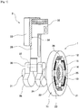
- FIG. 1 is an explanatory diagram showing the configuration of an engine starter system according to one embodiment of the present invention.
- the engine starter system of FIG. 1 includes a starter 1, which employs an SR motor or a type of brushless motor, and an engine 2, which is started by the starter 1.
- the engine in the present embodiment, in order to make the system configuration easier to understand, the engine is constituted of a single cylinder, and peripheral members such as cylinder blocks and motor cases, are omitted from FIG. 1 .
- the starter 1 is an inner rotor-type electric motor.
- the starter 1 includes a stator 11, which is secured inside the motor case not shown in the diagram, and a rotor 21, which is disposed inside the stator 11 in a rotatable manner.
- the stator 11 is made up of a large number of thin electromagnetic steel plates that are stacked.
- the stator 11 includes a ring-shaped yoke 12 and poles 13.
- the poles 13 are radially protruding from the yoke 12 toward the radial-direction inner side (toward the center).
- the gap between the adjacent poles 13 serves as a slot 14.
- the poles 13 and the slots 14 are formed in such a way as to be the same in size (with the same central angle).
- Six poles 13 are disposed along the circumferential direction in such a way as to be spaced apart from one another at regular intervals.
- a coil 15 is wound.
- the coils 15 are multiple phase coils (or three pairs of U-phase, V-phase and W-phase coils 15U, 15V and 15W in this case), to which currents of different phases are supplied.
- the coils 15 that face each other have the same phase.
- Currents are sequentially supplied to the three pairs of coils 15, thereby forming rotating magnetic fields of three phases (U-phase, V-phase and W-phase) inside the stator 1.
- the rotor 21 is inserted in such a way as to share the axis with the stator 11 and be capable of rotating relative to the stator 11.
- the rotor 21 is directly connected to a crank shaft 31 of the engine 2 and therefore rotates together with the crank shaft 31.
- the rotor 21 includes a rotor core 22 and a rotor body 23, which is fixed to the inner side of the rotor core 22.
- the rotor core 22 is made up of a large number of thin electromagnetic steel plates that are stacked.
- the rotor body 23 is fixed to a crank journal 24 with attachment bolts 25.
- the crank journal 24 is formed in an end portion of the crank shaft 31.
- the crank journal 24 is supported by main bearings (not shown) in a rotatable manner on a cylinder block.
- salient poles 26 are disposed protruding toward the radial-direction outer side.
- the four salient poles 26 are equally spaced out along the circumferential direction.
- the salient poles 26 are of the same size as the poles 13 and slots 14 (with the same central angle).
- the rotation angle of the rotor 21 is detected by a resolver (not shown).
- the engine controller sequentially excites each phase coil 15U, 15V or 15W in accordance with the angular position of the rotor 21.
- a coil 15 When a coil 15 is excited, a pole 13 where that coil 15 is wound around starts acting as a magnetic pole, thereby forming a rotating magnetic field in the stator 1.
- the salient pole 26 of the rotor 21 is attracted by the magnetized pole 13, and the rotor 21 starts to rotate inside the stator 11 as a result.
- the engine 2 has a piston 32, which is connected to the crank shaft 31.
- the piston 32 is disposed in a cylinder bore 34, which is formed in a cylinder block 33.
- the position of the piston 32 inside the cylinder bore 34 is constantly detected by a piston position sensor (not shown).
- the crank shaft 31 is provided with crank arms 35 and counter weights 36. Between the crank arms 35, a crank pin 37 is attached. To the crank pin 37, a connecting rod 38 is attached to link the piston 32 and the crank shaft 31.
- the starter 1 causes the crank arms 35 to rotate, thereby moving the piston 32 up and down.
- fuel is injected into the cylinder bore 34 so that combustion and explosions occur appropriately. In this manner, the engine 2 is started.
- the positional relationship between the rotor 21 and the crank shaft 31 is set so that a rotor rotation position where the torque of the starter 1 is at its maximum matches a crank shaft rotation position where engine friction torque is at its maximum. That is, the starter 1 and the engine 2 are mechanically set in such a way that the peaks of respective torque ripple waveforms match each other.
- the engine friction torque is at its maximum when the piston 32 is positioned at the top dead center, which is a maximum pass-over torque position.
- the output torque of the starter 1 is at its maximum when, as shown in FIG. 2 , a pair of salient poles 26 (26a, 26c) face poles 13 (e.g. U-phase poles 13U) and the other pair of salient poles 26 (26b, 26d) are between the adjacent poles 13.
- the poles 13 similarly, W-phase poles 13W
- the largest attraction force acts on the salient poles 26b and 26d, whereby the starter 1 rotates with maximum torque.
- the rotor 21 is mounted on the crank shaft 31 so that the rotor 21 is in the situation shown in FIG. 2 at a time when the piston 32 is at the top dead center-position or slightly beyond the top dead center-position (those positions will be referred to as "top dead center-position or the like"). Therefore, in the engine starter system of the present invention, the engine can be started with the motor's maximum torque, and an efficient engine start operation is possible without relying on surplus output power. Accordingly, in this system, even if an SR motor, which has large torque ripples, is used, malfunctioning does not occur, such as not being able to exceed a maximum pass-over torque. As a result, it is possible to reliably start the engine with a minimum-output motor, as well as to make the starter 1 smaller and improve the reliability of the system.
- FIG. 3 is a flowchart showing the control procedure of the engine starter system: FIG. 3A shows the system being stopped, and FIG. 3B shows the system being restarted.
- the present embodiment is based on the assumption that the engine of an idling-stopped vehicle is being restarted.
- the engine controller issues an engine stop command (Step S1).
- the position of the piston 32 is detected and judged (Step S2).
- the engine controller which issued the engine stop command, sends electricity only through the U-phase coils of the starter 1 after the piston 32 comes close to the top dead center-position (Step S3).
- the starter 1 stops with the salient poles 26a and 26c facing the U-phase poles 13U.
- the starter 1 is set in such a way that, when the salient poles 26a and 26c face the U-phase poles 13U, the piston 32 is at the top dead center-position or the like (Step S4). Accordingly, the rotor 21 is stopped and restrained with the piston 32 at the top dead center-position or the like (Step S5).
- Step S12 When the engine is restarted, from the top dead center-position restraining state (from Step S5 to S11), electricity is being supplied only through W-phase coils (Step S12), which are adjacent to the U-phase coils (or adjacent to the U-phase coils on the side opposite to the rotor rotation direction) and differ in phase.
- the salient poles 26b and 26d are attracted by the W-phase poles 13W, and the starter 1 rotates with maximum torque (the state shown in FIG. 2 ). That is, the engine is started with the maximum torque of the starter 1 when the engine is at the engine friction torque maximum position (top dead center) . Accordingly, it is possible to reliably start the engine by making maximum use of the motor output. After that, different coils are sequentially excited, and the rotor 21 is rotated to start the engine (Step S13).
- the positional relationship of the piston with the rotor is mechanically set in such a way that when the friction torque is at its maximum during the process of starting the engine, the motor's output comes to its maximum.
- preparations for restart is also made when the engine is stopped: Electricity is supplied only to one predetermined phase so that the rotor is stopped and retained at a position where the motor' s output is at its maximum (where the friction torque is at its maximum as well). That is, standby control is conducted by simply supplying electricity through the one phase, so that when the engine comes to a halt, the rotor is placed at the best position for restart next time.
- the system according to the present invention is applied to the single-cylinder engine.
- This system can also be applied to engines of multiple cylinders, such as four-cylinder and six-cylinder.
- fluctuations of engine friction torque are smaller than in the single-cylinder engine.
- ripples which are a combination of torque ripples of each cylinder.
- the crank shaft position where the combined ripples are at their maximum is matched with the maximum torque position of the starter 1. This similarly enables the efficient, reliable start of the engine.
- the settings are made in such a way that when the salient poles 26 face the U-phase poles 13U, the piston 32 comes to the top dead center-position (or the position where the engine friction torque is at its maximum).
- the phase of poles 13 designed to stop and restrain salient poles 26 is not limited to U-phase, and can be any one of the U-phase, V-phase and W-phase. Even in such a case, when the engine is started, the adjacent phase is excited, and the starter 1 is started with maximum torque (V-phase stop ⁇ U-phase start, W-phase stop ⁇ V-phase start).
- the number of poles 13 of the starter 1 is 6, and the number of salient poles 26 is 4.
- the numbers of poles 13 and salient poles 26 are not limited to those.
- the starter 1 is an inner rotor-type electric motor where a rotor is disposed inside the stator in such a way as to freely rotate relative to the stator.
- the present invention can also be applied to an outer rotor-type electric motor in which a rotor is disposed outside a stator in such a way as to freely rotate relative to the stator.
- the above starter 1 can function not only to start the engine but also as a power generator.
- electricity is instantaneously supplied to the coils 15 of those poles 13.
- magnetic flux is generated at the coils 15.
- the magnetic flux is cut by the freewheeling salient poles 26 and induced current emerges at the coil 15.
- the above operation is conducted when the accelerator is off, power-generation action occurs, causing a braking force on the engine (regeneration brake).
- the SR motor no magnet is used in the rotor. Therefore, the weight is small, with no effect on depletion of rare earth resources.
- the engine is accelerated (when no electricity is flowing through coils), no power-generation action would occur, thereby putting little burden on the engine and improving the gas mileage. Since the device is made only from steel material, it is high in strength and suitable for severe usage conditions.
- the present invention is applied to the stopping and restarting of the engine of an idling-stopped vehicle.
- the present invention can also be applied to the stopping and starting of the engine of a vehicle that does not feature such an idling-stop.
- the present invention can be applied not only to the engine starter system with the SR motor, but also widely applied to starter systems with motors that can control where a rotor is stopped.
- the present invention can be applied to starter systems using motors that can stop and retain a rotor at a predetermined location, such as stepping motors or synchronous reluctance motors that have slits in a rotor, form d-q axis and are driven only by reluctance torque.
Landscapes
- Engineering & Computer Science (AREA)
- Power Engineering (AREA)
- Chemical & Material Sciences (AREA)
- Combustion & Propulsion (AREA)
- Mechanical Engineering (AREA)
- General Engineering & Computer Science (AREA)
- Connection Of Motors, Electrical Generators, Mechanical Devices, And The Like (AREA)
- Control Of Vehicle Engines Or Engines For Specific Uses (AREA)
Abstract
Description
- The present invention relates to an engine starter system using an electric motor.
- To start an engine, an engine starter using an electric motor has heretofore been used. For example,
Patent Document 1 discloses an engine starter/generator that use an SR motor (Switched Reluctance Motor). In recent years, as an engine-starter motor, SR motors whose structure is simple and solid has gained attention. Especially, the use of SR motors is expanding against the backdrop of a surge in the prices of rare earths, as the motors do not employ permanent magnets in rotors. In the case of the starter/generator disclosed inPatent Document 1, the rotation shaft of a motor is connected to the crankshaft of an engine via a clutch or reducer; The starter/generator functions as a starter (power machine) when an engine is being stopped, and as a generator (power generator) after the start of the engine. - Patent Document 1:
JP 2001-28851A - Meanwhile, the engine has a rotation friction, which further has periodic fluctuations (ripples). Accordingly, when the engine is started, the torque for rotating the crankshaft (cranking torque) differs according to where a piston is inside a cylinder. In the case of a conventional starter motor using a magnet rotor, a surplus output power of the motor is used to address the ripples of the engine friction torque.
- However, a drive-source electric motor, too, has torque ripples. Particularly, the SR motor tends to have larger torque ripples than magnet motors. As described above, in the case of the conventional engine starter, the engine-side torque ripples are addressed by the surplus output power, while the motor's torque ripples are somewhat left out of consideration. If the motor's and engine's torque ripples work against each other, the engine may not start as the motor torque is overwhelmed by the cranking torque.
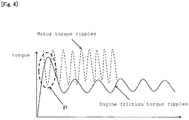
- As indicated in area P in
FIG. 4 , if the peak of the ripple of engine friction torque coincides with the trough of the ripple of motor torque, the motor torque may be less than the cranking torque as long as it depends on the surplus output power. That is, the motor torque may not be able to exceed a pass-over torque (maximum pass-over torque) at a time when it passes over the top dead center of the first compression stroke since the engine's start (which is a compression stroke of a four-cycle engine or a suction/compression stroke for a two-cycle engine) and could result in malfunction. In this case, such concerns would not rise if the trough of the motor torque is set in such a way as to surpass the peak of the engine friction torque. However, the problem is that increasing the motor torque inevitably requires the motor to be larger in size. - According to an aspect of the present invention, there is provided an engine starter system for starting an engine using an electric motor, wherein the electric motor includes a stator, which has a plurality of poles and coils wound around each of the poles, and a rotor, which is disposed in such a way as to share an axis with the stator; the rotor is connected to a crank shaft of the engine and rotates in sync with the crank shaft; and the rotor and the crank shaft are connected together in such a way that when a piston of the engine is at a top dead center or slightly beyond the top dead center, a predetermined pole faces a predetermined location of the rotor.
- In the present invention, the positional relationship between the piston and the rotor is mechanically set in such a way that when the piston of the engine is at the top dead center or slightly beyond the top dead center, a predetermined pole comes to face a predetermined location of the rotor. When the piston of the engine is at the top dead center or slightly beyond the top dead center, the friction torque comes to its maximum when the engine is started. Accordingly, it is possible to overcome a maximum friction torque with maximum output, and the engine therefore can be started by a minimum-output motor.
- In the engine starter system, when the engine is stopped, electricity may be supplied to a predetermined coil, and a predetermined location of the rotor is therefore stopped to face the predetermined pole, and the piston is stopped at a top dead center or slightly beyond the top dead center. When the engine is started, electricity may be supplied to the coil that is different from the coil through which electricity is supplied when the engine is stopped, in order to drive the electric motor.
- The poles are mounted in such a way as to protrude toward a radial-direction inner side of the stator; the rotor has a plurality of salient poles protruding toward a radial-direction outer side; and when the piston of the engine is at a top dead center or slightly beyond the top dead center, a predetermined salient pole faces a predetermined pole. In this case, the coils are phase coils of multiple phases through which currents of different phases are supplied; and when the engine is stopped, electricity is supplied to one phase of the phase coils so that the predetermined salient pole is stopped facing the predetermined pole, thereby letting the piston stop at a top dead center or slightly beyond the top dead center. When the engine is started, electricity is supplied to an adjacent phase coil of a different phase from the phase coil through which electricity is supplied when the engine is stopped, in order to drive the electric motor.
- According to another aspect of the present invention, there is provided an engine starter system for starting an engine using an electric motor, wherein the electric motor includes a stator, which has a plurality of poles and coils wound around each of the poles, and a rotor, which is disposed in such a way as to share an axis with the stator; the rotor is connected to a crank shaft of the engine and rotates in sync with the crank shaft; and the rotor and the crank shaft are connected in such a way that an output torque of the electric motor comes to its maximum at a maximum pass-over torque position of the engine.
- In the present invention, the positional relationship between the piston and the rotor is mechanically set in such a way that when the friction torque is at its maximum during the process of starting the engine, the output of the motor comes to its maximum as well. Therefore, it is possible to overcome a maximum friction torque with maximum output, and the engine therefore can be started with a minimum-output motor.
- In the engine starter system, when the engine is stopped, electricity is supplied to a predetermined coil to make the rotor stop at a position corresponding to a maximum pass-over torque position of the engine. When the engine is started, electricity is supplied to the coil that is different from the coil to which electricity is supplied when the engine is stopped, in order to drive the electric motor.
- The coils are phase coils of multiple phases through which currents of different phases are supplied; and when the engine is stopped, electricity is supplied to one phase of the phase coils so that the rotor comes to a halt at a position corresponding to a maximum pass-over torque position of the engine. When the engine is started, electricity is supplied to the phase coil of a different phase from the phase to which electricity is supplied when the engine is stopped, so that an output torque of the electric motor comes to its maximum, in order to drive the electric motor.
- In an aspect of the engine starter system of the present invention, the positional relationship between the piston and the rotor is set in such a way that when the piston of the engine is at the top dead center or slightly beyond the top dead center, a predetermined pole faces a predetermined location of the rotor. As a result, it is possible to overcome the top dead center-position, where the friction torque is at its maximum when the engine is started, with the maximum output of the motor. Accordingly, the engine can be started by a minimum-output motor, the engine starter can be reduced in size, and the reliability of the system can be improved.
- In another aspect of the engine starter system of the present invention, the positional relationship between the piston and the rotor is set in such a way that an output torque of the electric motor comes to its maximum at a maximum pass-over torque position when the engine is started. As a result, it is possible to overcome the maximum pass-over torque when the engine is started, with the maximum output of the motor. Accordingly, the engine can be started by a minimum-output motor, the engine starter can be reduced in size, and the reliability of the system can be improved.
-
-
FIG. 1 is an explanatory diagram showing the configuration of an engine starter system according to one embodiment of the present invention. -
FIG. 2 is an explanatory diagram showing the positional relationship between a rotor and a piston in the engine starter system ofFIG. 1 . -
FIG. 3 is a flowchart showing a control procedure of the engine starter system:FIG. 3A shows a state of the system being stopped, andFIG. 3B shows a state of the system being restarted. -
FIG. 4 is an explanatory diagram showing the relationship between motor's torque ripples and ripples of engine friction torque. - Hereinafter, an embodiment of the present invention will be described based on the accompanying drawings. The object of the embodiment described below is to provide an engine starter system capable of reliably starting an engine with a minimum-output motor.
FIG. 1 is an explanatory diagram showing the configuration of an engine starter system according to one embodiment of the present invention. The engine starter system ofFIG. 1 includes astarter 1, which employs an SR motor or a type of brushless motor, and anengine 2, which is started by thestarter 1. Incidentally, in the present embodiment, in order to make the system configuration easier to understand, the engine is constituted of a single cylinder, and peripheral members such as cylinder blocks and motor cases, are omitted fromFIG. 1 . - The
starter 1 is an inner rotor-type electric motor. Thestarter 1 includes astator 11, which is secured inside the motor case not shown in the diagram, and arotor 21, which is disposed inside thestator 11 in a rotatable manner. Thestator 11 is made up of a large number of thin electromagnetic steel plates that are stacked. Thestator 11 includes a ring-shaped yoke 12 andpoles 13. Thepoles 13 are radially protruding from theyoke 12 toward the radial-direction inner side (toward the center). The gap between theadjacent poles 13 serves as aslot 14. In thestator 1, thepoles 13 and theslots 14 are formed in such a way as to be the same in size (with the same central angle). Sixpoles 13 are disposed along the circumferential direction in such a way as to be spaced apart from one another at regular intervals. - On the outer periphery of the
pole 13, acoil 15 is wound. To thecoils 15, currents are supplied from a battery under the control of an engine controller. Thecoils 15 are multiple phase coils (or three pairs of U-phase, V-phase and W-phase coils coils 15 that face each other have the same phase. Currents are sequentially supplied to the three pairs ofcoils 15, thereby forming rotating magnetic fields of three phases (U-phase, V-phase and W-phase) inside thestator 1. - Inside the
stator 11, therotor 21 is inserted in such a way as to share the axis with thestator 11 and be capable of rotating relative to thestator 11. Therotor 21 is directly connected to a crankshaft 31 of theengine 2 and therefore rotates together with thecrank shaft 31. Therotor 21 includes arotor core 22 and arotor body 23, which is fixed to the inner side of therotor core 22. Therotor core 22 is made up of a large number of thin electromagnetic steel plates that are stacked. Therotor body 23 is fixed to a crankjournal 24 withattachment bolts 25. Thecrank journal 24 is formed in an end portion of thecrank shaft 31. Thecrank journal 24 is supported by main bearings (not shown) in a rotatable manner on a cylinder block. On the outer periphery of therotor core 22,salient poles 26 are disposed protruding toward the radial-direction outer side. The foursalient poles 26 are equally spaced out along the circumferential direction. Thesalient poles 26 are of the same size as thepoles 13 and slots 14 (with the same central angle). - In the
starter 1, the rotation angle of therotor 21 is detected by a resolver (not shown). The engine controller sequentially excites eachphase coil rotor 21. When acoil 15 is excited, apole 13 where thatcoil 15 is wound around starts acting as a magnetic pole, thereby forming a rotating magnetic field in thestator 1. Thesalient pole 26 of therotor 21 is attracted by themagnetized pole 13, and therotor 21 starts to rotate inside thestator 11 as a result. - The
engine 2 has apiston 32, which is connected to thecrank shaft 31. Thepiston 32 is disposed in a cylinder bore 34, which is formed in acylinder block 33. The position of thepiston 32 inside the cylinder bore 34 is constantly detected by a piston position sensor (not shown). Thecrank shaft 31 is provided with crankarms 35 andcounter weights 36. Between the crankarms 35, acrank pin 37 is attached. To thecrank pin 37, a connectingrod 38 is attached to link thepiston 32 and thecrank shaft 31. When the engine is started, thestarter 1 causes the crankarms 35 to rotate, thereby moving thepiston 32 up and down. At the same time, fuel is injected into the cylinder bore 34 so that combustion and explosions occur appropriately. In this manner, theengine 2 is started. - In this engine starter system, the positional relationship between the
rotor 21 and thecrank shaft 31 is set so that a rotor rotation position where the torque of thestarter 1 is at its maximum matches a crank shaft rotation position where engine friction torque is at its maximum. That is, thestarter 1 and theengine 2 are mechanically set in such a way that the peaks of respective torque ripple waveforms match each other. - Generally, the engine friction torque is at its maximum when the
piston 32 is positioned at the top dead center, which is a maximum pass-over torque position. Meanwhile, the output torque of thestarter 1 is at its maximum when, as shown inFIG. 2 , a pair of salient poles 26 (26a, 26c) face poles 13 (e.g.U-phase poles 13U) and the other pair of salient poles 26 (26b, 26d) are between theadjacent poles 13. At this time, if the poles 13 (similarly, W-phase poles 13W) of thestarter 1 are excited, the largest attraction force acts on thesalient poles starter 1 rotates with maximum torque. - Accordingly, in the
starter 1, therotor 21 is mounted on thecrank shaft 31 so that therotor 21 is in the situation shown inFIG. 2 at a time when thepiston 32 is at the top dead center-position or slightly beyond the top dead center-position (those positions will be referred to as "top dead center-position or the like"). Therefore, in the engine starter system of the present invention, the engine can be started with the motor's maximum torque, and an efficient engine start operation is possible without relying on surplus output power. Accordingly, in this system, even if an SR motor, which has large torque ripples, is used, malfunctioning does not occur, such as not being able to exceed a maximum pass-over torque. As a result, it is possible to reliably start the engine with a minimum-output motor, as well as to make thestarter 1 smaller and improve the reliability of the system. - In the engine starter system with the above-described configuration, in order to make best use of its structural advantages, motor control is conducted as follows.
FIG. 3 is a flowchart showing the control procedure of the engine starter system:FIG. 3A shows the system being stopped, andFIG. 3B shows the system being restarted. The present embodiment is based on the assumption that the engine of an idling-stopped vehicle is being restarted. As shown inFIG. 3 , when a vehicle comes to a stop, the engine controller issues an engine stop command (Step S1). Then, the position of thepiston 32 is detected and judged (Step S2). - The engine controller, which issued the engine stop command, sends electricity only through the U-phase coils of the
starter 1 after thepiston 32 comes close to the top dead center-position (Step S3). As a result, thestarter 1 stops with thesalient poles 26a and 26c facing theU-phase poles 13U. As described above, thestarter 1 is set in such a way that, when thesalient poles 26a and 26c face theU-phase poles 13U, thepiston 32 is at the top dead center-position or the like (Step S4). Accordingly, therotor 21 is stopped and restrained with thepiston 32 at the top dead center-position or the like (Step S5). - When the engine is restarted, from the top dead center-position restraining state (from Step S5 to S11), electricity is being supplied only through W-phase coils (Step S12), which are adjacent to the U-phase coils (or adjacent to the U-phase coils on the side opposite to the rotor rotation direction) and differ in phase. As a result, the
salient poles phase poles 13W, and thestarter 1 rotates with maximum torque (the state shown inFIG. 2 ). That is, the engine is started with the maximum torque of thestarter 1 when the engine is at the engine friction torque maximum position (top dead center) . Accordingly, it is possible to reliably start the engine by making maximum use of the motor output. After that, different coils are sequentially excited, and therotor 21 is rotated to start the engine (Step S13). - In this manner, in the engine starter system of the present invention, the positional relationship of the piston with the rotor is mechanically set in such a way that when the friction torque is at its maximum during the process of starting the engine, the motor's output comes to its maximum. Moreover, preparations for restart is also made when the engine is stopped: Electricity is supplied only to one predetermined phase so that the rotor is stopped and retained at a position where the motor' s output is at its maximum (where the friction torque is at its maximum as well). That is, standby control is conducted by simply supplying electricity through the one phase, so that when the engine comes to a halt, the rotor is placed at the best position for restart next time. When the engine is started, this allows the motor to be driven with maximum torque only by supplying electricity to the adjacent, next phase, and the maximum friction torque can be exceeded with maximum output. Therefore, unlike conventional systems that are dependent on surplus output power, a motor of optimal output and size can be used for the engine, and the engine starter can be reduced in size and the reliability of the system can be improved.
- The present invention is not limited to the above-described embodiment, and various changes may be made without departing from the spirit of the invention.
- For example, in the above-described embodiment, the system according to the present invention is applied to the single-cylinder engine. This system can also be applied to engines of multiple cylinders, such as four-cylinder and six-cylinder. In multiple-cylinder engines, fluctuations of engine friction torque are smaller than in the single-cylinder engine. But there are still ripples, which are a combination of torque ripples of each cylinder. In accordance with the characteristics of each engine, the crank shaft position where the combined ripples are at their maximum is matched with the maximum torque position of the
starter 1. This similarly enables the efficient, reliable start of the engine. - In the above-described embodiment, the settings are made in such a way that when the
salient poles 26 face theU-phase poles 13U, thepiston 32 comes to the top dead center-position (or the position where the engine friction torque is at its maximum). However, the phase ofpoles 13 designed to stop and restrainsalient poles 26 is not limited to U-phase, and can be any one of the U-phase, V-phase and W-phase. Even in such a case, when the engine is started, the adjacent phase is excited, and thestarter 1 is started with maximum torque (V-phase stop → U-phase start, W-phase stop → V-phase start). - Furthermore, in the above example, the number of
poles 13 of thestarter 1 is 6, and the number ofsalient poles 26 is 4. However, the numbers ofpoles 13 andsalient poles 26 are not limited to those. In addition, thestarter 1 is an inner rotor-type electric motor where a rotor is disposed inside the stator in such a way as to freely rotate relative to the stator. The present invention can also be applied to an outer rotor-type electric motor in which a rotor is disposed outside a stator in such a way as to freely rotate relative to the stator. - The
above starter 1 can function not only to start the engine but also as a power generator. For example, when the rotor rotates and thesalient poles 26 are aligned with thepoles 13, electricity is instantaneously supplied to thecoils 15 of thosepoles 13. Owing to the electricity, magnetic flux is generated at thecoils 15. But the magnetic flux is cut by the freewheelingsalient poles 26 and induced current emerges at thecoil 15. Accordingly, if the above operation is conducted when the accelerator is off, power-generation action occurs, causing a braking force on the engine (regeneration brake). In this case, in the SR motor, no magnet is used in the rotor. Therefore, the weight is small, with no effect on depletion of rare earth resources. When the engine is accelerated (when no electricity is flowing through coils), no power-generation action would occur, thereby putting little burden on the engine and improving the gas mileage. Since the device is made only from steel material, it is high in strength and suitable for severe usage conditions. - In the above-described control example, the present invention is applied to the stopping and restarting of the engine of an idling-stopped vehicle. The present invention can also be applied to the stopping and starting of the engine of a vehicle that does not feature such an idling-stop.
- The present invention can be applied not only to the engine starter system with the SR motor, but also widely applied to starter systems with motors that can control where a rotor is stopped. For example, the present invention can be applied to starter systems using motors that can stop and retain a rotor at a predetermined location, such as stepping motors or synchronous reluctance motors that have slits in a rotor, form d-q axis and are driven only by reluctance torque.
-
- 1:
- Starter
- 2:
- Engine
- 11:
- Stator
- 12:
- Yoke
- 13:
- Pole
- 13U:
- U-phase pole
- 13W:
- W-phase pole
- 14:
- Slot
- 15:
- Coil
- 15U:
- U-phase coil
- 15V:
- V-phase coil
- 15W:
- W-phase coil
- 21:
- Rotor
- 22:
- Rotor core
- 23:
- Rotor body
- 24:
- Crank journal
- 25:
- Attachment bolt
- 26:
- Salient pole
- 26a to 26d:
- Salient pole
- 31:
- Crank shaft
- 32:
- Piston
- 33:
- Cylinder block
- 34:
- Cylinder bore
- 35:
- Crank arm
- 36:
- Counter weight
- 37:
- Crank pin
- 38:
- Connecting rod
Claims (11)
- An engine starter system for starting an engine using an electric motor, characterized in that
the electric motor includes a stator, which has a plurality of poles and coils wound around each of the poles, and a rotor, which is disposed in such a way as to share an axis with the stator;
the rotor is connected to a crank shaft of the engine and rotates in sync with the crank shaft; and
the rotor and the crank shaft are connected together in such a way that when a piston of the engine is at a top dead center or slightly beyond the top dead center, a predetermined pole faces a predetermined location of the rotor. - The engine starter system according to claim 1, characterized in that
when the engine is stopped, electricity is supplied to a predetermined coil, and a predetermined location of the rotor is therefore stopped to face the predetermined pole, and the piston is stopped at a top dead center or slightly beyond the top dead center. - The engine starter system according to claim 2, characterized in that
when the engine is started, electricity is supplied to the coil that is different from the coil through which electricity is supplied when the engine is stopped. - The engine starter system according to claim 1, characterized in that
the poles are mounted in such a way as to protrude toward a radial-direction inner side of the stator;
the rotor is disposed inside the stator and has a plurality of salient poles protruding toward a radial-direction outer side; and
when the piston of the engine is at a top dead center or slightly beyond the top dead center, a predetermined salient pole faces a predetermined pole. - The engine starter system according to claim 4, characterized in that
the coils are phase coils of multiple phases through which currents of different phases are supplied; and
when the engine is stopped, electricity is supplied to one phase of the phase coils so that the predetermined salient pole is stopped facing the predetermined pole, thereby letting the piston stop at a top dead center or slightly beyond the top dead center. - The engine starter system according to claim 5, characterized in that
when the engine is started, electricity is supplied to an adjacent coil of a different phase from the phase coil through which electricity is supplied when the engine is stopped. - An engine starter system for starting an engine using an electric motor, characterized in that
the electric motor includes a stator, which has a plurality of poles and coils wound around each of the poles, and a rotor, which is disposed in such a way as to share an axis with the stator;
the rotor is connected to a crank shaft of the engine and rotates in sync with the crank shaft; and
the rotor and the crank shaft are connected in such a way that an output torque of the electric motor comes to its maximum at a maximum pass-over torque position of the engine. - The engine starter system according to claim 7, characterized in that
when the engine is stopped, electricity is supplied to a predetermined coil to make the rotor stop at a position corresponding to a maximum pass-over torque position of the engine. - The engine starter system according to claim 8, characterized in that
when the engine is started, electricity is supplied to the coil that is different from the coil to which electricity is supplied when the engine is stopped. - The engine starter system according to claim 7, characterized in that
the coils are phase coils of multiple phases through which currents of different phases are supplied; and
when the engine is stopped, electricity is supplied to one phase of the phase coils so that the rotor comes to a halt at a position corresponding to a maximum pass-over torque position of the engine. - The engine starter system according to claim 10, characterized in that
when the engine is started, electricity is supplied to the phase coil of a different phase from the phase to which electricity is supplied when the engine is stopped, so that an output torque of the electric motor comes to its maximum.
Applications Claiming Priority (2)
| Application Number | Priority Date | Filing Date | Title |
|---|---|---|---|
| JP2015122170A JP6462503B2 (en) | 2015-06-17 | 2015-06-17 | Engine starter system |
| PCT/JP2016/067497 WO2016204109A1 (en) | 2015-06-17 | 2016-06-13 | Engine starter system |
Publications (2)
| Publication Number | Publication Date |
|---|---|
| EP3312411A1 true EP3312411A1 (en) | 2018-04-25 |
| EP3312411A4 EP3312411A4 (en) | 2019-07-03 |
Family
ID=57546631
Family Applications (1)
| Application Number | Title | Priority Date | Filing Date |
|---|---|---|---|
| EP16811583.0A Withdrawn EP3312411A4 (en) | 2015-06-17 | 2016-06-13 | Engine starter system |
Country Status (5)
| Country | Link |
|---|---|
| US (1) | US10138857B2 (en) |
| EP (1) | EP3312411A4 (en) |
| JP (1) | JP6462503B2 (en) |
| CN (1) | CN107683370B (en) |
| WO (1) | WO2016204109A1 (en) |
Families Citing this family (3)
| Publication number | Priority date | Publication date | Assignee | Title |
|---|---|---|---|---|
| US11448146B2 (en) * | 2015-11-12 | 2022-09-20 | Bombardier Recreational Products Inc. | Method and system for starting an internal combustion engine |
| RU2726148C2 (en) | 2015-11-12 | 2020-07-09 | Бомбардье Рекриэйшенел Продактс Инк. | Method and system for starting an internal combustion engine |
| CN112865656B (en) * | 2019-11-26 | 2026-05-05 | 海信冰箱有限公司 | A refrigerator compressor driving method and a variable frequency compressor and refrigerator |
Family Cites Families (20)
| Publication number | Priority date | Publication date | Assignee | Title |
|---|---|---|---|---|
| JPS58176569A (en) | 1982-04-09 | 1983-10-17 | Hitachi Ltd | Detecting method for neutron and gamma rays |
| JPS58176569U (en) * | 1982-05-21 | 1983-11-25 | 日産自動車株式会社 | Internal combustion engine starting device |
| JPH0386095A (en) * | 1989-08-28 | 1991-04-11 | Secoh Giken Inc | 3-phase reluctance type motor |
| US5327069A (en) * | 1992-06-19 | 1994-07-05 | General Electric Company | Switched reluctance machine including permanent magnet stator poles |
| US6442535B1 (en) * | 1998-10-28 | 2002-08-27 | Emerson Electric Co. | Method and apparatus for implementing a low cost, intelligent controller for a switched reluctance machine |
| JP2001028851A (en) | 1999-07-13 | 2001-01-30 | Nissan Motor Co Ltd | Motor and starter generator |
| JP2003111488A (en) * | 2001-10-02 | 2003-04-11 | Toyota Industries Corp | Control method and control device for switch reluctance motor and compressor |
| TW575718B (en) * | 2001-12-11 | 2004-02-11 | Honda Motor Co Ltd | Method of starting an electric brushless rotating machine for driving an internal combustion engine |
| JP2003189675A (en) * | 2001-12-11 | 2003-07-04 | Honda Motor Co Ltd | Starting method of brushless rotating electric machine for driving internal combustion engine |
| DE102004007393A1 (en) * | 2003-02-28 | 2004-09-09 | Denso Corp., Kariya | Machine starter with a starter motor |
| JP2004308645A (en) * | 2003-03-25 | 2004-11-04 | Denso Corp | Engine starter |
| US7201244B2 (en) * | 2003-10-03 | 2007-04-10 | Letourneau, Inc. | Vehicle for materials handling and other industrial uses |
| US20070204827A1 (en) * | 2006-03-02 | 2007-09-06 | Kokusan Denki Co., Ltd. | Engine starting device |
| JP2008061453A (en) * | 2006-09-01 | 2008-03-13 | Denso Corp | In-vehicle motor controller |
| JP4412355B2 (en) * | 2007-06-08 | 2010-02-10 | 株式会社デンソー | Shift range switching device |
| JP4406453B2 (en) * | 2007-10-03 | 2010-01-27 | トヨタ自動車株式会社 | Shift switching device |
| JP5662870B2 (en) * | 2011-05-17 | 2015-02-04 | 本田技研工業株式会社 | Engine generator start control device |
| KR101301385B1 (en) * | 2011-09-20 | 2013-09-10 | 삼성전기주식회사 | Speed control apparatus for the switched reluctance motor |
| JP5993616B2 (en) * | 2012-05-25 | 2016-09-14 | 日立オートモティブシステムズ株式会社 | Electric motor drive control device |
| US20170187315A1 (en) * | 2015-12-24 | 2017-06-29 | Toyota Jidosha Kabushiki Kaisha | Control device for switched reluctance motor |
-
2015
- 2015-06-17 JP JP2015122170A patent/JP6462503B2/en active Active
-
2016
- 2016-06-13 US US15/735,317 patent/US10138857B2/en active Active
- 2016-06-13 CN CN201680034493.8A patent/CN107683370B/en active Active
- 2016-06-13 WO PCT/JP2016/067497 patent/WO2016204109A1/en not_active Ceased
- 2016-06-13 EP EP16811583.0A patent/EP3312411A4/en not_active Withdrawn
Also Published As
| Publication number | Publication date |
|---|---|
| WO2016204109A1 (en) | 2016-12-22 |
| JP6462503B2 (en) | 2019-01-30 |
| US10138857B2 (en) | 2018-11-27 |
| US20180171959A1 (en) | 2018-06-21 |
| EP3312411A4 (en) | 2019-07-03 |
| CN107683370B (en) | 2020-07-28 |
| CN107683370A (en) | 2018-02-09 |
| JP2017008741A (en) | 2017-01-12 |
Similar Documents
| Publication | Publication Date | Title |
|---|---|---|
| CA2638495C (en) | Generator for vehicle | |
| TWI551776B (en) | Engine unit and vehicle | |
| US20120175989A1 (en) | Permanent magnet excited synchronous machine with embedded magnets | |
| TWI528680B (en) | Engine unit and vehicle | |
| JP6004038B2 (en) | Rotating electric machine for internal combustion engine and method for manufacturing the same | |
| US10138857B2 (en) | Engine starter system | |
| US8492914B2 (en) | Crank-web mounted linearly segmented starter generator system | |
| JP2015074296A (en) | Vehicle drive system | |
| JP2017031808A (en) | Engine unit and vehicle | |
| EP2528207A1 (en) | Brushless electric machine | |
| WO2014209873A1 (en) | Charging apparatus for a combustion engine | |
| EP1560317A2 (en) | Brushless exciter with electromagnetically decoupled dual excitation systems for starter-generator applications | |
| US20100283243A1 (en) | Method for controlling a self-piloted alternator-starter, including a shortened prefulx step | |
| KR20020090335A (en) | Synchronisati0n of machine and load characteristics | |
| JP2017041963A (en) | Motor generator | |
| JP2017036666A (en) | Engine unit | |
| TW202129145A (en) | Straddled vehicle | |
| WO2018030153A1 (en) | Three-phase rotary electric machine for starter generator | |
| CN102570656A (en) | Electric-excitation brushless starter generator (motor) | |
| TWI557313B (en) | Engine unit and vehicle | |
| JP7168787B2 (en) | Generator motor for internal combustion engine | |
| US20230361636A1 (en) | Electric machine having asymmetric magnet arrangement | |
| CN110870179A (en) | Vehicle propulsion system | |
| JP2017036665A (en) | Engine unit | |
| RU136936U1 (en) | BRACKETLESS ELECTRIC MOTOR WITH EXTERNAL CONE MULTI-POLE MAGNETIC SYSTEM |
Legal Events
| Date | Code | Title | Description |
|---|---|---|---|
| STAA | Information on the status of an ep patent application or granted ep patent |
Free format text: STATUS: THE INTERNATIONAL PUBLICATION HAS BEEN MADE |
|
| PUAI | Public reference made under article 153(3) epc to a published international application that has entered the european phase |
Free format text: ORIGINAL CODE: 0009012 |
|
| STAA | Information on the status of an ep patent application or granted ep patent |
Free format text: STATUS: REQUEST FOR EXAMINATION WAS MADE |
|
| 17P | Request for examination filed |
Effective date: 20180103 |
|
| AK | Designated contracting states |
Kind code of ref document: A1 Designated state(s): AL AT BE BG CH CY CZ DE DK EE ES FI FR GB GR HR HU IE IS IT LI LT LU LV MC MK MT NL NO PL PT RO RS SE SI SK SM TR |
|
| AX | Request for extension of the european patent |
Extension state: BA ME |
|
| DAV | Request for validation of the european patent (deleted) | ||
| DAX | Request for extension of the european patent (deleted) | ||
| A4 | Supplementary search report drawn up and despatched |
Effective date: 20190531 |
|
| RIC1 | Information provided on ipc code assigned before grant |
Ipc: F02N 11/04 20060101AFI20190524BHEP Ipc: F02N 19/00 20100101ALI20190524BHEP Ipc: H02K 19/10 20060101ALI20190524BHEP Ipc: H02K 3/18 20060101ALI20190524BHEP Ipc: H02P 25/08 20160101ALI20190524BHEP |
|
| STAA | Information on the status of an ep patent application or granted ep patent |
Free format text: STATUS: EXAMINATION IS IN PROGRESS |
|
| 17Q | First examination report despatched |
Effective date: 20220121 |
|
| STAA | Information on the status of an ep patent application or granted ep patent |
Free format text: STATUS: THE APPLICATION IS DEEMED TO BE WITHDRAWN |
|
| 18D | Application deemed to be withdrawn |
Effective date: 20240103 |