EP3312376A1 - Roller blind - Google Patents
Roller blind Download PDFInfo
- Publication number
- EP3312376A1 EP3312376A1 EP17198161.6A EP17198161A EP3312376A1 EP 3312376 A1 EP3312376 A1 EP 3312376A1 EP 17198161 A EP17198161 A EP 17198161A EP 3312376 A1 EP3312376 A1 EP 3312376A1
- Authority
- EP
- European Patent Office
- Prior art keywords
- lateral
- transverse bar
- blind
- magnetic coupling
- coupling element
- Prior art date
- Legal status (The legal status is an assumption and is not a legal conclusion. Google has not performed a legal analysis and makes no representation as to the accuracy of the status listed.)
- Granted
Links
- 230000005291 magnetic effect Effects 0.000 claims abstract description 119
- 230000008878 coupling Effects 0.000 claims abstract description 85
- 238000010168 coupling process Methods 0.000 claims abstract description 85
- 238000005859 coupling reaction Methods 0.000 claims abstract description 85
- 239000004744 fabric Substances 0.000 claims abstract description 49
- 238000000926 separation method Methods 0.000 claims description 3
- 238000004026 adhesive bonding Methods 0.000 description 3
- 229910052782 aluminium Inorganic materials 0.000 description 3
- XAGFODPZIPBFFR-UHFFFAOYSA-N aluminium Chemical compound [Al] XAGFODPZIPBFFR-UHFFFAOYSA-N 0.000 description 3
- 238000001125 extrusion Methods 0.000 description 3
- 239000000463 material Substances 0.000 description 3
- 229910052751 metal Inorganic materials 0.000 description 3
- 239000002184 metal Substances 0.000 description 3
- 210000002105 tongue Anatomy 0.000 description 3
- 238000004804 winding Methods 0.000 description 3
- 241000255925 Diptera Species 0.000 description 2
- 239000003795 chemical substances by application Substances 0.000 description 2
- 239000003302 ferromagnetic material Substances 0.000 description 2
- 238000001914 filtration Methods 0.000 description 2
- 230000005389 magnetism Effects 0.000 description 2
- 238000004519 manufacturing process Methods 0.000 description 2
- 230000009471 action Effects 0.000 description 1
- 238000005452 bending Methods 0.000 description 1
- 230000005540 biological transmission Effects 0.000 description 1
- 230000015556 catabolic process Effects 0.000 description 1
- 238000006731 degradation reaction Methods 0.000 description 1
- 230000005484 gravity Effects 0.000 description 1
- 230000003116 impacting effect Effects 0.000 description 1
- 230000003993 interaction Effects 0.000 description 1
- 230000014759 maintenance of location Effects 0.000 description 1
- 239000005445 natural material Substances 0.000 description 1
- 230000003647 oxidation Effects 0.000 description 1
- 238000007254 oxidation reaction Methods 0.000 description 1
- 230000001681 protective effect Effects 0.000 description 1
- 230000008439 repair process Effects 0.000 description 1
- 230000037072 sun protection Effects 0.000 description 1
Images


Classifications
-
- E—FIXED CONSTRUCTIONS
- E06—DOORS, WINDOWS, SHUTTERS, OR ROLLER BLINDS IN GENERAL; LADDERS
- E06B—FIXED OR MOVABLE CLOSURES FOR OPENINGS IN BUILDINGS, VEHICLES, FENCES OR LIKE ENCLOSURES IN GENERAL, e.g. DOORS, WINDOWS, BLINDS, GATES
- E06B9/00—Screening or protective devices for wall or similar openings, with or without operating or securing mechanisms; Closures of similar construction
- E06B9/56—Operating, guiding or securing devices or arrangements for roll-type closures; Spring drums; Tape drums; Counterweighting arrangements therefor
- E06B9/80—Safety measures against dropping or unauthorised opening; Braking or immobilising devices; Devices for limiting unrolling
-
- E—FIXED CONSTRUCTIONS
- E04—BUILDING
- E04F—FINISHING WORK ON BUILDINGS, e.g. STAIRS, FLOORS
- E04F10/00—Sunshades, e.g. Florentine blinds or jalousies; Outside screens; Awnings or baldachins
- E04F10/02—Sunshades, e.g. Florentine blinds or jalousies; Outside screens; Awnings or baldachins of flexible canopy materials, e.g. canvas ; Baldachins
- E04F10/06—Sunshades, e.g. Florentine blinds or jalousies; Outside screens; Awnings or baldachins of flexible canopy materials, e.g. canvas ; Baldachins comprising a roller-blind with means for holding the end away from a building
- E04F10/0607—Sunshades, e.g. Florentine blinds or jalousies; Outside screens; Awnings or baldachins of flexible canopy materials, e.g. canvas ; Baldachins comprising a roller-blind with means for holding the end away from a building with guiding-sections for supporting the movable end of the blind
-
- E—FIXED CONSTRUCTIONS
- E06—DOORS, WINDOWS, SHUTTERS, OR ROLLER BLINDS IN GENERAL; LADDERS
- E06B—FIXED OR MOVABLE CLOSURES FOR OPENINGS IN BUILDINGS, VEHICLES, FENCES OR LIKE ENCLOSURES IN GENERAL, e.g. DOORS, WINDOWS, BLINDS, GATES
- E06B9/00—Screening or protective devices for wall or similar openings, with or without operating or securing mechanisms; Closures of similar construction
- E06B9/24—Screens or other constructions affording protection against light, especially against sunshine; Similar screens for privacy or appearance; Slat blinds
- E06B9/40—Roller blinds
- E06B9/42—Parts or details of roller blinds, e.g. suspension devices, blind boxes
-
- E—FIXED CONSTRUCTIONS
- E06—DOORS, WINDOWS, SHUTTERS, OR ROLLER BLINDS IN GENERAL; LADDERS
- E06B—FIXED OR MOVABLE CLOSURES FOR OPENINGS IN BUILDINGS, VEHICLES, FENCES OR LIKE ENCLOSURES IN GENERAL, e.g. DOORS, WINDOWS, BLINDS, GATES
- E06B9/00—Screening or protective devices for wall or similar openings, with or without operating or securing mechanisms; Closures of similar construction
- E06B9/52—Devices affording protection against insects, e.g. fly screens; Mesh windows for other purposes
- E06B9/54—Roller fly screens
-
- E—FIXED CONSTRUCTIONS
- E06—DOORS, WINDOWS, SHUTTERS, OR ROLLER BLINDS IN GENERAL; LADDERS
- E06B—FIXED OR MOVABLE CLOSURES FOR OPENINGS IN BUILDINGS, VEHICLES, FENCES OR LIKE ENCLOSURES IN GENERAL, e.g. DOORS, WINDOWS, BLINDS, GATES
- E06B9/00—Screening or protective devices for wall or similar openings, with or without operating or securing mechanisms; Closures of similar construction
- E06B9/56—Operating, guiding or securing devices or arrangements for roll-type closures; Spring drums; Tape drums; Counterweighting arrangements therefor
- E06B9/58—Guiding devices
-
- E—FIXED CONSTRUCTIONS
- E06—DOORS, WINDOWS, SHUTTERS, OR ROLLER BLINDS IN GENERAL; LADDERS
- E06B—FIXED OR MOVABLE CLOSURES FOR OPENINGS IN BUILDINGS, VEHICLES, FENCES OR LIKE ENCLOSURES IN GENERAL, e.g. DOORS, WINDOWS, BLINDS, GATES
- E06B9/00—Screening or protective devices for wall or similar openings, with or without operating or securing mechanisms; Closures of similar construction
- E06B9/56—Operating, guiding or securing devices or arrangements for roll-type closures; Spring drums; Tape drums; Counterweighting arrangements therefor
- E06B9/80—Safety measures against dropping or unauthorised opening; Braking or immobilising devices; Devices for limiting unrolling
- E06B9/82—Safety measures against dropping or unauthorised opening; Braking or immobilising devices; Devices for limiting unrolling automatic
- E06B9/86—Safety measures against dropping or unauthorised opening; Braking or immobilising devices; Devices for limiting unrolling automatic against unauthorised opening
-
- E—FIXED CONSTRUCTIONS
- E06—DOORS, WINDOWS, SHUTTERS, OR ROLLER BLINDS IN GENERAL; LADDERS
- E06B—FIXED OR MOVABLE CLOSURES FOR OPENINGS IN BUILDINGS, VEHICLES, FENCES OR LIKE ENCLOSURES IN GENERAL, e.g. DOORS, WINDOWS, BLINDS, GATES
- E06B9/00—Screening or protective devices for wall or similar openings, with or without operating or securing mechanisms; Closures of similar construction
- E06B9/56—Operating, guiding or securing devices or arrangements for roll-type closures; Spring drums; Tape drums; Counterweighting arrangements therefor
- E06B9/80—Safety measures against dropping or unauthorised opening; Braking or immobilising devices; Devices for limiting unrolling
- E06B2009/801—Locking arrangements
- E06B2009/805—Locking arrangements located on or in the guides
Definitions
- the present invention regards a roller blind according to the preamble of the independent claim number 1.
- the present roller blind is intended to be advantageously employed for adjustably closing provided openings made in walls of buildings, verandas, pergolas, roofs, etc. and in particular for adjustably closing windows, doors, French windows, skylights and similar window/door items.
- the blind, object of the present invention is therefore inserted in the industrial field of production of windows/doors/shutters, or also in the field of production of sun-protection blinds, in the field of mosquito screens or similar applications.
- Roller blinds are known on the market for closing window/door openings (such as windows, doors or French windows) provided with a rolling-shutter box which is fixed to a building wall or to a ceiling above the opening to be closed and at its interior houses a roller, on which a flexible fabric is susceptible of being wound and unwound.
- window/door openings such as windows, doors or French windows
- a rolling-shutter box which is fixed to a building wall or to a ceiling above the opening to be closed and at its interior houses a roller, on which a flexible fabric is susceptible of being wound and unwound.
- the fabric of the blind usually has rectangular shape and is provided with an upper edge fixed to the roller and with a lower edge fixed to a transverse bar aimed to stretch the fabric itself.
- the transverse bar comprises two lateral ends slidably coupled to the respective lateral guides.
- Each lateral guide is obtained with a corresponding aluminum profile of rectangular section, internally hollow and provided with an internal side (facing the internal side of the other lateral guide) on which a longitudinal slit is made, in which the corresponding lateral end of the transverse bar is slidably inserted.
- each lateral guide is longitudinally extended between an upper end, fixed to the rolling-shutter box, and a lower end closed by a base terminal fixed to the floor at the lower edge of the opening.
- the roller of the blind is drivable, typically by a motor, to rotate in order to move the fabric between a collected position, in which the fabric is wound around the roller with the transverse bar arranged in abutment against the rolling-shutter box, and an extended position, in which the fabric is unwound from the roller to close the opening and the transverse bar is arranged at the base terminals placed at the lower ends of the lateral guides.
- blinds are known on the market which are provided with locking devices adapted to lock the transverse bar to the base terminals when the fabric is brought into the extended position, and to unlock the transverse bar from the base terminals when it is necessary to wind the fabric again around the roller in order to bring the fabric into the collected position.
- each locking device comprises a coupling lever which is hinged to the corresponding base terminal and comprises a first arm fixed to a spring constrained to the base terminal itself.
- the coupling lever comprises a second arm provided at its free end with a pin susceptible of being slidably inserted within a shaped channel made in the corresponding lateral end of the transverse bar.
- the shaped channel of the lateral end is provided on the lower part with an inlet opening, in order to allow the pin of the coupling lever to enter into the shaped channel, and is provided at the upper part with an outlet opening in order to allow the pin of the coupling lever to exit from the shaped channel itself.
- the pin of the coupling lever enters into the shaped channel of the corresponding end until it reaches a specific stop section, in which the pin is constrained following the action of the spring that acts on the coupling lever, in a manner such that the latter is engaged with the corresponding lateral end in order to lock the transverse bar to the base ends of the lateral guides.
- the transverse bar In order to wind the fabric again, the transverse bar is controlled to descend until the pin of the coupling lever exits from the outlet opening of the shaped channel, by bending the aforesaid flexible tongue, in a manner so as to release the coupling lever from the corresponding lateral end of the transverse bar. Subsequently, the transverse bar is controlled to ascend in order to allow the winding of the fabric around the roller of the blind.
- a further drawback of the above-described blind of known type is due to the fact that the locking device tends to be jammed, in particular if impacted in an accidental manner, necessitating the execution of repair operations that require dismantling the locking device, the corresponding lateral guide and the transverse bar of the blind.
- the problem underlying the present invention is to provide a roller blind which is structurally simple and inexpensive to make.
- reference number 1 overall indicates a roller blind, object of the present invention.
- the present roller blind 1 is intended to carry out the adjustable closing of an opening A made on a load-bearing structure, such as a building wall, a veranda, a loggia, a terrace, a pergola, a roof or other similar structures.
- a load-bearing structure such as a building wall, a veranda, a loggia, a terrace, a pergola, a roof or other similar structures.
- the blind 1 is intended to close an opening A with substantially vertical plane, for example made on a building wall.
- the blind 1 is intended to close an opening A with substantially horizontal plane or tilted, made for example on the roof of a pergola.
- the support frame 2 of the blind 1 advantageously comprises a rolling-shutter box 3 intended to be positioned to delimit a head side at the opening A, and susceptible of being fixed to a wall of the load-bearing element preferably by means of anchorage brackets.
- the fabric 4 can be intended for making a shading screen for filtering the sunlight or for making a mosquito screen.
- the fabric 4 can be dedicated to closing the opening A in order to protect an internal or underlying area from the sun, from the wind, from the rain or, more generally, from weathering agents.
- the fabric 4 as a function of its different applications, can be made of synthetic or natural material fabric and can have the form of a mesh or have a continuous surface of shading, filtering or transparent type.
- the blind 1 also comprises two lateral guides 5 extended parallel to each other and side-by-side and advantageously placed to delimit corresponding sides of the opening A. Between the lateral guides 5, the fabric 4 is susceptible of sliding following its winding and unwinding around the take-up roller.
- the fabric 4 preferably has rectangular shape and is provided, in a manner per se known to the man skilled in the art, with a first edge fixed to the take-up roller and with a second edge fixed to a transverse bar 6 arranged parallel to the take-up roller and aimed to stretch the fabric 4.
- the fabric 4 is provided with two lateral edges 7, each provided with a flexible engagement flap 8 that is guided to slide along the corresponding lateral guide 5 during the winding and unwinding of the fabric 4 itself.
- the lateral guides 5 and the transverse bar 6 of the blind 1 identify a lying plane of the blind 1 itself, in particular such lying plane identifying a first side and a second side of the blind 1 directed in opposite direction with respect to each other.
- each lateral guide 5 is longitudinally extended according to a respective first extension direction Y substantially orthogonal to the rotation axis X of the take-up roller.
- each lateral guide 5 is extended along the corresponding first extension direction Y between a first end 9 and an opposite second end 10.
- the first end 9 of each lateral guide 5 is positioned at the take-up roller, and preferably leaned against the rolling-shutter box 3 of the blind 1, the second end 10 being arranged at a greater distance from the take-up roller with respect to the first end 9.
- the two lateral guides 5 are intended to be fixed to the load-bearing element (in which the opening A itself is obtained) for example by means of anchorage screws 11.
- the two lateral guides 5 are intended to be fixed, at the first ends 9 thereof, to the rolling-shutter box 3, and are intended to be supported, at the second ends 10, by columns of the load-bearing element.
- each lateral guide 5 has transverse section with preferably rectangular shape and is provided with an external surface 12 which comprises a first lateral side 13 directed towards the first lateral side 13 of the other lateral guide 5, and a second lateral side 14 directed in a direction substantially opposite with respect to the corresponding first lateral side 13 and preferably parallel to the latter.
- the external surface 12 of each lateral guide 5 is provided with a frontal face 15 extended to connect the first lateral side 13 with the second lateral side 14, and preferably orthogonal to such lateral sides 13, 14.
- each lateral guide 5 is provided with another frontal face 15' (it too extended to connect the first lateral side 13 with the second lateral side 14), directed in the direction opposite the aforesaid frontal face 15 and preferably parallel to the latter.
- each lateral guide 5 faces the first side of the blind 1 and is substantially parallel to the lying plane of the latter.
- the other frontal face 15' of each lateral guide 5 faces the second side of the blind 1.
- a longitudinal opening 17 is made that is parallel to the extension direction Y of the lateral guide 5 itself.
- the transverse bar 6 is slidably engaged in such longitudinal opening 17.
- each lateral guide 5 comprises at least one elongated profile extended longitudinally according to the extension direction Y between the first end 9 and the second end 10, made for example of aluminum and in particular by means of extrusion.
- each lateral guide 5 comprises a support profile 18 intended to be fixed to the load-bearing element, e.g. by means of the anchorage screws 11, and a guide profile 19 mechanically fixed to the aforesaid support profile and on which the corresponding longitudinal opening 17 is obtained.
- each lateral guide 5 comprises a single elongated profile made of a single body, e.g. by means of extrusion.
- each lateral guide 5 can comprise an end cap, for example made of plastic material, placed to close the second end 10 of the lateral guide 5 itself.
- the blind 1 comprises two rails 20, each of which mechanically associated with the corresponding lateral guide 5 and provided with a longitudinal groove adapted slidably receive the engagement flap 8 of the corresponding lateral edge 7 of the fabric 4.
- each lateral guide 5 is provided with an internal seat 21 connected to the longitudinal opening 17 of the lateral guide 5 itself and in which the corresponding rail 20 is housed in retention relationship, positioned with its longitudinal groove towards the longitudinal opening 17.
- each engagement flap 8 of the fabric 4 is obtained with a flexible toothing laterally projecting from the corresponding lateral edge 7, suitably reinforced with support strip.
- the rail 20 has elongated box shape, advantageously obtained via extrusion in plastic material, e.g. with quadrangular form section, with one side partially open with the longitudinal groove through which the fabric 4 passes.
- the transverse bar 6 of the blind 1, fixed to the second edge of the fabric 4, is longitudinally extended along a second extension direction Z parallel to the rotation axis X of the take-up roller, between two lateral ends 22 thereof slidably engaged in the longitudinal openings 17 of the corresponding lateral guides 5.
- the transverse bar 6 is provided with a front face 23 parallel to the frontal faces 15 of the lateral guides 5 and preferably coplanar to such frontal faces 15.
- the front face 23 of the transverse bar 6 is directed in the same direction as the frontal faces 15, in particular facing - together with the latter - the first side of the blind 1.
- the transverse bar 6 is provided with another front face 23' directed in the direction opposite the aforesaid front face 23 and preferably parallel to the latter.
- Such other front face 23' is directed in the same direction as the other frontal faces 15' of the lateral guides 5, in particular facing - together with these other frontal faces 15' - the second side of the blind 1.
- the transverse bar 6 comprises a metal section 6', e.g. of extruded aluminum.
- the lateral ends 22 of the transverse bar 6 are preferably made of plastic material, are placed to laterally close the metal section 6' of the transverse bar 6 itself and are fixed to the metal section 6' by means of connections screws (not illustrated), for example.
- each lateral end 22 of the transverse bar 6 is provided with a guide tab 24 laterally projecting as an extension of the transverse bar 6 itself according to the second extension direction Z and slidably inserted in the longitudinal opening 17 of the corresponding lateral guide 5.
- the thickness D1 of the guide tab 17 is smaller than the width D2 of the longitudinal opening 17 of the lateral guide 5 in order to define a sliding clearance.
- the blind 1 comprises driving means (not illustrated in the enclosed figures) mechanically connected to the take-up roller and arranged so to drive the latter to rotate around its rotation axis X in order to unwind or wind the fabric 4 around the take-up roller itself.
- the driving means are of motorized type (comprising in particular an electric motor), or of manual type (comprising in particular a crank obtained with a control rod engaged through an articulation to the shaft of the roller).
- the fabric 4 of the blind 1 is movable from the take-up roller between a collected position, in which the fabric 4 is wound around the take-up roller (as illustrated in the example of figure 1b ), and an extended position, in which the fabric 4 is unwound from the take-up roller to outside the rolling-shutter box 3 to close the opening A (as illustrated in the example of figure 1a ).
- the blind 1 comprises at least one first magnetic coupling element 25 fixed to the corresponding lateral guide 5 and in particular only positioned at the second end 10 of the lateral guide 5 itself.
- the blind 1 also comprises at least one second magnetic coupling element 26, which is fixed to the transverse bar 6 and is provided with a lateral appendage 27 projectingly extended in front of the frontal face 15 of the external surface 12 of the corresponding lateral guide 5, outside the latter.
- the second magnetic coupling element 26 is positioned in front of the first magnetic coupling element 25 and substantially faces the latter.
- the blind 1 comprises a pair of the aforesaid first magnetic coupling elements 25, each fixed to the corresponding lateral guide 5, and a pair of aforesaid second magnetic coupling elements 26, each fixed to the lateral bar 6 and susceptible of interacting via magnetic attraction with the corresponding first magnetic coupling element 25 in order to retain the transverse bar 6 locked in the closed position.
- the two second magnetic coupling elements 26 are separate from each other and arranged at the respective lateral ends 22 of the transverse bar 6.
- the two second magnetic coupling elements 26 are made in only one element fixed to the transverse bar 6 with the two lateral appendages 27 extended in front of the corresponding lateral guides 5.
- the first magnetic coupling element 25 is provided with one or more first magnetic bodies 28 and the lateral appendage 27 of the second magnetic coupling element 26 is provided with one or more second magnetic bodies 29.
- magnetic body it is intended a body which, due to its own magnetism or due to induced magnetism (induced by an external magnetic field), is capable of attracting objects of ferromagnetic material.
- the first magnetic coupling element 25 comprises at least one first row of multiple first magnetic bodies 28 and the second magnetic coupling element 26 comprises at least one second row of multiple second magnetic bodies 29 which, when the transverse bar 6 is in the closed position, interact via magnetic attraction with the corresponding first magnetic bodies 28 of the aforesaid first row, in particular being arranged in front of such corresponding first magnetic bodies 28.
- the first magnetic body 28 comprises a first permanent magnet (such as a first magnet)
- the second magnetic body 29 comprises a second permanent magnet (such as a second magnet) with polarity opposite that of the first permanent magnet of the corresponding first magnetic body 28 to which it is magnetically attracted when the transverse bar 6 is in closed position.
- the first magnetic body 28 comprises a permanent magnetic body and the second magnetic body 29 comprises a body made of ferromagnetic material, or vice versa.
- the first magnetic coupling element 25 is fixed on the frontal face 15 of the external surface 12 of the corresponding lateral guide 5, for example by means of first fixing screws (not illustrated in the enclosed figures) and/or by means of gluing.
- the first magnetic coupling element 25 is provided with an external face 25' which, when the transverse bar 6 is in the closed position, faces the lateral appendage 27 of the second magnetic coupling element 26.
- the first magnetic coupling element 25 projectingly extends from the frontal face 15 of the corresponding lateral guide 5.
- the first magnetic coupling element 25 is embedded in the frontal face 15 of the corresponding lateral guide 5, in particular being positioned with its external face 25' coplanar with the frontal face 15 itself.
- the lateral appendage 27 of the second magnetic coupling element 26 is extended, according to the second extension direction Z, beyond the corresponding lateral end 22 of the transverse bar 6, in a manner so as to face the frontal face 15 of the corresponding lateral guide 5, and to face in front of the corresponding first magnetic coupling element 25 when the transverse bar 6 is in the closed position.
- the second magnetic coupling element 26 is fixed on the front face 23 of the transverse bar 6, for example by means of second fixing screws (not illustrated in the enclosed figures) and/or by means of gluing.
- the second magnetic coupling element 26 comprises an attachment portion 30 fixed to the front face 23 of the transverse bar 6 and projectingly extended from such front face 23.
- Fixed to the attachment portion 30 is the corresponding lateral appendage 28, which is projectingly extended from the attachment portion 30 parallel to the second extension direction Z, extended in front of the frontal face 15 of the corresponding lateral guide 5.
- the lateral appendage 27 is integrally made with the attachment portion 30. Otherwise, the lateral appendage 27 and the attachment portion 30 are made in a separate manner and integrally fixed to each other.
- the lateral appendage 27 of the second magnetic coupling element 26 is provided with an internal face 31 directed towards the frontal face 15 of the corresponding lateral guide 5 and arranged preferably spaced from the frontal face 15 itself.
- a passage cavity 32 is made in which the corresponding first magnetic coupling element 25 is inserted when the transverse bar 6 is in closed position, in a manner so as to allow the lateral appendage 27 to be arranged in front of the first magnetic coupling element 25 without impacting the latter and preventing the movement of the transverse bar 6 itself.
- the lateral appendage 27 of the second magnetic coupling element 26 is connected to the corresponding attachment portion 30 with a substantially elbow-shaped connector that advantageously delimits the aforesaid passage cavity 32.
- the second magnetic body 29 of the second magnetic coupling element 26 is fixed to the lateral appendage 27 by means of for example third fixing screws (not illustrated) and/or gluing. Otherwise, the second magnetic body 29 is integrally made with the lateral appendage 27.
- the second magnetic coupling element 26 comes into contact with the first magnetic coupling element 25 following the magnetic attraction generated therebetween.
- the internal face 31 of the lateral appendage 27 of the second magnetic coupling element 26 comes into contact with the external face 25' of the first magnetic coupling element 25, advantageously developing a friction force between the internal face 31 and the external face 25'.
- the second magnetic coupling element 26 is coupled in contact with the first magnetic coupling element 25 following a movement of the transverse bar 6 (caused by the magnetic attraction between the coupling elements 25, 26) orthogonal to the lying plane of the blind 1 and which is advantageously allowed by the sliding clearance with which the guide tab 24 of each lateral end 22 of the frontal bar 6 is inserted in the longitudinal opening 17 of the corresponding lateral guide 5.
- the first magnetic coupling element 25 comprises a first protection casing 33 placed to cover the first magnetic body 28, preferably defining the external face 25' of the first magnetic coupling element 25 itself.
- the second magnetic coupling element 26 comprises a second protection casing 34 placed to cover the second magnetic body 29, preferably defining the internal face 31 of the lateral appendage 27 of the second magnetic coupling element 26 itself.
- the aforesaid protection casings 33, 34 are advantageously adapted to protect the magnetic bodies 28, 29 from external agents (such as moisture, etc.) in order to prevent the possible degradation thereof (due for example to oxidation).
- first magnetic coupling elements 25 and the second magnetic coupling elements 26 are respectively arranged on the frontal faces 15 of the lateral guides 5 and on the front face 23 of the transverse bar 6.
- first magnetic coupling elements 25 and the second magnetic coupling elements 26 can be respectively arranged on the other frontal faces 15' of the lateral guides 5 and on the other front face 23' of the transverse bar 6.
- the take-up roller In operation, in order to move the fabric 4 of the blind 1 from the collected position to the extended position, the take-up roller is driven by the driving means for the blind 1 to rotate in a first rotation direction in order to unwind the fabric 4 from the take-up roller itself. Consequently, the transverse bar 6 slides along the lateral guides 5 from the open position thereof (in which it is arranged at the first ends 9 of the lateral guides 5) to the closed position thereof (in which it is arranged at the second ends 10 of the lateral guides 5).
- the transverse bar 6 is thrust towards the second ends 10 of the lateral guides 5 by suitable actuation means arranged within the lateral guides 5 and comprising for example springs connected to the transverse bar 6 by means of transmission pulleys, in a manner per se known to the man skilled in the art and therefore not described in detail in the present document.
- each second magnetic coupling element 26 is attracted via magnetic attraction against the corresponding first magnetic coupling element 25 (preferably coming into contact with the latter) in a manner so as to retain the transverse bar 6 locked to the guides 5 at the second ends 10 thereof, in order to fix the fabric 4 in the extended position.
- the magnetic interaction between the first magnetic body 28 and the corresponding second magnetic body 29 determines a magnetic field having direction, at the magnetic bodies 28, 29 themselves, substantially orthogonal to the lying plane of the blind 1 in a manner so as to attract the magnetic bodies 28, 29 towards each other.
- the take-up roller is driven to rotate in a second rotation direction in order to wind the fabric again on itself.
- the fabric 4 exerts a separation force on the transverse bar 6 such to overcome the magnetic attraction between the corresponding first and second magnetic coupling elements 25, 26, in a manner so as to allow the transverse bar 6 to be moved away from the second ends 10 of the lateral guides 5, sliding along the latter so as to allow the fabric 4 to be wound again around the take-up roller.
- the electric motor of the driving means for the blind 1 is arranged for generating a starting torque, exerted on the take-up roller, which generates a separation force on the transverse bar 6 greater than the magnetic attraction force between the corresponding first and second magnetic coupling elements 25, 26, allowing the second magnetic coupling elements 26 to move away from the corresponding first magnetic coupling elements 25 in order to allow the movement of the transverse bar 6 and of the fabric 4.
- the invention thus conceived therefore attains the pre-established objects.
- the arrangement of the first magnetic coupling elements 25 on the lateral guides 5 and of the second magnetic coupling elements 26 on the transverse bar 6 allows reliably locking the transverse bar 6 in the closed position by means of an arrangement of the blind 1 that is simple and inexpensive to make, in particular allowing the easy application of the magnetic coupling elements 25, 26 even on pre-existing blinds models without having to execute complex redesigning of the latter.
Landscapes
- Engineering & Computer Science (AREA)
- Structural Engineering (AREA)
- Architecture (AREA)
- Civil Engineering (AREA)
- Life Sciences & Earth Sciences (AREA)
- Insects & Arthropods (AREA)
- Pest Control & Pesticides (AREA)
- Tents Or Canopies (AREA)
- Operating, Guiding And Securing Of Roll- Type Closing Members (AREA)
- Blinds (AREA)
Abstract
Description
- The present invention regards a roller blind according to the preamble of the
independent claim number 1. - The present roller blind is intended to be advantageously employed for adjustably closing provided openings made in walls of buildings, verandas, pergolas, roofs, etc. and in particular for adjustably closing windows, doors, French windows, skylights and similar window/door items.
- The blind, object of the present invention, is therefore inserted in the industrial field of production of windows/doors/shutters, or also in the field of production of sun-protection blinds, in the field of mosquito screens or similar applications.
- Roller blinds are known on the market for closing window/door openings (such as windows, doors or French windows) provided with a rolling-shutter box which is fixed to a building wall or to a ceiling above the opening to be closed and at its interior houses a roller, on which a flexible fabric is susceptible of being wound and unwound. An example of a blind of this type is described in the patent
GB 2479976 - The fabric of the blind usually has rectangular shape and is provided with an upper edge fixed to the roller and with a lower edge fixed to a transverse bar aimed to stretch the fabric itself.
- In addition, the blind comprises two lateral guides vertically arranged along the corresponding sides of the opening and to which the transverse bar is slidably constrained.
- In particular, the transverse bar comprises two lateral ends slidably coupled to the respective lateral guides.
- Each lateral guide is obtained with a corresponding aluminum profile of rectangular section, internally hollow and provided with an internal side (facing the internal side of the other lateral guide) on which a longitudinal slit is made, in which the corresponding lateral end of the transverse bar is slidably inserted.
- In addition, each lateral guide is longitudinally extended between an upper end, fixed to the rolling-shutter box, and a lower end closed by a base terminal fixed to the floor at the lower edge of the opening.
- In operation, the roller of the blind is drivable, typically by a motor, to rotate in order to move the fabric between a collected position, in which the fabric is wound around the roller with the transverse bar arranged in abutment against the rolling-shutter box, and an extended position, in which the fabric is unwound from the roller to close the opening and the transverse bar is arranged at the base terminals placed at the lower ends of the lateral guides.
- In particular, blinds are known on the market which are provided with locking devices adapted to lock the transverse bar to the base terminals when the fabric is brought into the extended position, and to unlock the transverse bar from the base terminals when it is necessary to wind the fabric again around the roller in order to bring the fabric into the collected position.
- More in detail, in accordance with the solution of known type described in the patent application
WO 2011/101879 , each locking device comprises a coupling lever which is hinged to the corresponding base terminal and comprises a first arm fixed to a spring constrained to the base terminal itself. - In addition, the coupling lever comprises a second arm provided at its free end with a pin susceptible of being slidably inserted within a shaped channel made in the corresponding lateral end of the transverse bar.
- More in detail, the shaped channel of the lateral end is provided on the lower part with an inlet opening, in order to allow the pin of the coupling lever to enter into the shaped channel, and is provided at the upper part with an outlet opening in order to allow the pin of the coupling lever to exit from the shaped channel itself.
- In addition, the lateral end of the transverse bar is provided with a flexible tongue placed to close the outlet opening of the shaped channel and arranged to prevent the pin of the coupling lever from entering into the shaped channel through such outlet opening, and arranged in order to be bent towards the exterior of the shaped channel in order to allow the pin to exit from the shaped channel through the outlet opening itself.
- In operation, when the transverse bar is at the base ends of the lateral guides in order to unwind the fabric, the pin of the coupling lever enters into the shaped channel of the corresponding end until it reaches a specific stop section, in which the pin is constrained following the action of the spring that acts on the coupling lever, in a manner such that the latter is engaged with the corresponding lateral end in order to lock the transverse bar to the base ends of the lateral guides.
- In order to wind the fabric again, the transverse bar is controlled to descend until the pin of the coupling lever exits from the outlet opening of the shaped channel, by bending the aforesaid flexible tongue, in a manner so as to release the coupling lever from the corresponding lateral end of the transverse bar. Subsequently, the transverse bar is controlled to ascend in order to allow the winding of the fabric around the roller of the blind.
- One drawback of the above-described blind of known type is due to the fact that it is structurally complex and costly to make, in particular requiring the arrangement of coupling levers and of specific lateral ends of the transverse bar with shaped channels and flexible tongues.
- A further drawback of the above-described blind of known type is due to the fact that the locking device tends to be jammed, in particular if impacted in an accidental manner, necessitating the execution of repair operations that require dismantling the locking device, the corresponding lateral guide and the transverse bar of the blind.
- In this situation, the problem underlying the present invention is to provide a roller blind which is structurally simple and inexpensive to make.
- Another object of the present invention is to provide a roller blind which is easy to install.
- Another object of the present invention is to provide a roller blind which is not subjected to jamming of the transverse bar movement.
- These and still other objects are all attained by the roller blind according to the enclosed claims.
- The technical characteristics of the invention, according to the aforesaid objects, can be clearly seen in the contents of the below-reported claims and the advantages thereof will be more evident in the following detailed description made with reference to the enclosed drawings, which represent several exemplifying and non-limiting embodiments of the invention, in which:
-
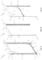
figures 1a, 1b and 1c show the roller blind, object of the present invention, in accordance with a first embodiment, in a perspective view with the fabric respectively completely extended, completely wound and partially extended; -
figure 2 shows a perspective view of a detail of the blind illustrated infigure 1a , relative to a lateral guide and to a bottom bar of the blind at a lateral end of the bottom bar itself; -
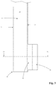
figure 3 shows a side view of the lateral guide and of the bottom bar illustrated infigure 2 ; -
figure 4 shows a section view of the lateral guide and of the bottom bar illustrated infigure 3 according to the trace IV-IV offigure 3 itself; -
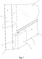
figure 5 shows the roller blind, object of the present invention, in accordance with a second embodiment. - With reference to the enclosed drawings,
reference number 1 overall indicates a roller blind, object of the present invention. - The present roller blind 1 is intended to carry out the adjustable closing of an opening A made on a load-bearing structure, such as a building wall, a veranda, a loggia, a terrace, a pergola, a roof or other similar structures.
- In particular, in accordance with a first embodiment illustrated in
figures 1a-c , the blind 1 is intended to close an opening A with substantially vertical plane, for example made on a building wall. In accordance with a second embodiment illustrated infigure 5 , the blind 1 is intended to close an opening A with substantially horizontal plane or tilted, made for example on the roof of a pergola. - In accordance with the embodiments illustrated in
figures 1a-c and5 , the blind 1 comprises asupport frame 2 intended to be fixed to a load-bearing element. In accordance with the first embodiment illustrated infigures 1a-c , the load-bearing element comprises a wall in which the opening A is made. In accordance with the second embodiment illustrated infigure 5 , the load-bearing element for example comprises two or more columns of the pergola and/or a wall against which the pergola itself leans. - The
support frame 2 of the blind 1 advantageously comprises a rolling-shutter box 3 intended to be positioned to delimit a head side at the opening A, and susceptible of being fixed to a wall of the load-bearing element preferably by means of anchorage brackets. - The blind 1 also comprises a take-up roller (not illustrated in the enclosed figures) rotatably constrained to the
support frame 2, advantageously housed within the rolling-shutter box 3, and provided with a rotation axis X that is preferably substantially horizontal. - The blind 1 also comprises a
flexible fabric 4, which is susceptible of being wound and unwound around the take-up roller and preferably passes through a passage slit of the rolling-shutter box 3 in order to enter into and exit from the latter. - The
fabric 4 can be intended for making a shading screen for filtering the sunlight or for making a mosquito screen. Generally, thefabric 4 can be dedicated to closing the opening A in order to protect an internal or underlying area from the sun, from the wind, from the rain or, more generally, from weathering agents. - The
fabric 4, as a function of its different applications, can be made of synthetic or natural material fabric and can have the form of a mesh or have a continuous surface of shading, filtering or transparent type. - The blind 1 also comprises two
lateral guides 5 extended parallel to each other and side-by-side and advantageously placed to delimit corresponding sides of the opening A. Between thelateral guides 5, thefabric 4 is susceptible of sliding following its winding and unwinding around the take-up roller. - The
fabric 4 preferably has rectangular shape and is provided, in a manner per se known to the man skilled in the art, with a first edge fixed to the take-up roller and with a second edge fixed to atransverse bar 6 arranged parallel to the take-up roller and aimed to stretch thefabric 4. In addition, thefabric 4 is provided with two lateral edges 7, each provided with a flexible engagement flap 8 that is guided to slide along the correspondinglateral guide 5 during the winding and unwinding of thefabric 4 itself. - Advantageously, the
lateral guides 5 and thetransverse bar 6 of the blind 1 identify a lying plane of the blind 1 itself, in particular such lying plane identifying a first side and a second side of the blind 1 directed in opposite direction with respect to each other. - According to the invention, each
lateral guide 5 is longitudinally extended according to a respective first extension direction Y substantially orthogonal to the rotation axis X of the take-up roller. - More in detail, each
lateral guide 5 is extended along the corresponding first extension direction Y between afirst end 9 and an oppositesecond end 10. Thefirst end 9 of eachlateral guide 5 is positioned at the take-up roller, and preferably leaned against the rolling-shutter box 3 of the blind 1, thesecond end 10 being arranged at a greater distance from the take-up roller with respect to thefirst end 9. - In accordance with the first embodiment illustrated in
figures 1a-4 , the twolateral guides 5 are intended to be fixed to the load-bearing element (in which the opening A itself is obtained) for example by means ofanchorage screws 11. - In accordance with the second embodiment illustrated in
figure 5 , the twolateral guides 5 are intended to be fixed, at thefirst ends 9 thereof, to the rolling-shutter box 3, and are intended to be supported, at thesecond ends 10, by columns of the load-bearing element. - With reference to the example of
figure 4 , eachlateral guide 5 has transverse section with preferably rectangular shape and is provided with anexternal surface 12 which comprises a firstlateral side 13 directed towards the firstlateral side 13 of the otherlateral guide 5, and a secondlateral side 14 directed in a direction substantially opposite with respect to the corresponding firstlateral side 13 and preferably parallel to the latter. In addition, theexternal surface 12 of eachlateral guide 5 is provided with afrontal face 15 extended to connect the firstlateral side 13 with the secondlateral side 14, and preferably orthogonal to suchlateral sides external surface 12 of eachlateral guide 5 is provided with another frontal face 15' (it too extended to connect the firstlateral side 13 with the second lateral side 14), directed in the direction opposite the aforesaidfrontal face 15 and preferably parallel to the latter. - In particular, the
frontal face 15 of eachlateral guide 5 faces the first side of the blind 1 and is substantially parallel to the lying plane of the latter. Suitably, the other frontal face 15' of eachlateral guide 5 faces the second side of the blind 1. - On the first
lateral side 13 of theexternal surface 12 of eachlateral guide 5, alongitudinal opening 17 is made that is parallel to the extension direction Y of thelateral guide 5 itself. Thetransverse bar 6 is slidably engaged in suchlongitudinal opening 17. - Advantageously, each
lateral guide 5 comprises at least one elongated profile extended longitudinally according to the extension direction Y between thefirst end 9 and thesecond end 10, made for example of aluminum and in particular by means of extrusion. In particular, in accordance with the first embodiment illustrated infigure 4 , eachlateral guide 5 comprises asupport profile 18 intended to be fixed to the load-bearing element, e.g. by means of the anchorage screws 11, and aguide profile 19 mechanically fixed to the aforesaid support profile and on which the correspondinglongitudinal opening 17 is obtained. - Otherwise, in accordance for example with the second embodiment illustrated in
figure 5 , eachlateral guide 5 comprises a single elongated profile made of a single body, e.g. by means of extrusion. - Suitably, in accordance with both the aforesaid embodiments, each
lateral guide 5 can comprise an end cap, for example made of plastic material, placed to close thesecond end 10 of thelateral guide 5 itself. - Advantageously, with reference to the example of
figure 4 , the blind 1 comprises tworails 20, each of which mechanically associated with the correspondinglateral guide 5 and provided with a longitudinal groove adapted slidably receive the engagement flap 8 of the corresponding lateral edge 7 of thefabric 4. - In particular, each
lateral guide 5 is provided with an internal seat 21 connected to thelongitudinal opening 17 of thelateral guide 5 itself and in which the correspondingrail 20 is housed in retention relationship, positioned with its longitudinal groove towards thelongitudinal opening 17. - The
rail 20 can assume different shapes in order to be coupled in sliding relationship with different embodiment solutions of engagement flaps 8 available on the market and fixed to the lateral edges 7 of thefabric 4. - For example, each engagement flap 8 of the
fabric 4 is obtained with a flexible toothing laterally projecting from the corresponding lateral edge 7, suitably reinforced with support strip. Correspondingly, therail 20 has elongated box shape, advantageously obtained via extrusion in plastic material, e.g. with quadrangular form section, with one side partially open with the longitudinal groove through which thefabric 4 passes. - The
transverse bar 6 of the blind 1, fixed to the second edge of thefabric 4, is longitudinally extended along a second extension direction Z parallel to the rotation axis X of the take-up roller, between two lateral ends 22 thereof slidably engaged in thelongitudinal openings 17 of the corresponding lateral guides 5. - Advantageously, the
transverse bar 6 is provided with afront face 23 parallel to the frontal faces 15 of the lateral guides 5 and preferably coplanar to such frontal faces 15. In addition, thefront face 23 of thetransverse bar 6 is directed in the same direction as the frontal faces 15, in particular facing - together with the latter - the first side of the blind 1. - Suitably, the
transverse bar 6 is provided with another front face 23' directed in the direction opposite the aforesaidfront face 23 and preferably parallel to the latter. Such other front face 23' is directed in the same direction as the other frontal faces 15' of the lateral guides 5, in particular facing - together with these other frontal faces 15' - the second side of the blind 1. - Preferably, the
transverse bar 6 comprises a metal section 6', e.g. of extruded aluminum. The lateral ends 22 of thetransverse bar 6 are preferably made of plastic material, are placed to laterally close the metal section 6' of thetransverse bar 6 itself and are fixed to the metal section 6' by means of connections screws (not illustrated), for example. Advantageously, eachlateral end 22 of thetransverse bar 6 is provided with aguide tab 24 laterally projecting as an extension of thetransverse bar 6 itself according to the second extension direction Z and slidably inserted in thelongitudinal opening 17 of the correspondinglateral guide 5. For such purpose, the thickness D1 of theguide tab 17 is smaller than the width D2 of thelongitudinal opening 17 of thelateral guide 5 in order to define a sliding clearance. - Advantageously, the blind 1 comprises driving means (not illustrated in the enclosed figures) mechanically connected to the take-up roller and arranged so to drive the latter to rotate around its rotation axis X in order to unwind or wind the
fabric 4 around the take-up roller itself. - In particular, the driving means are of motorized type (comprising in particular an electric motor), or of manual type (comprising in particular a crank obtained with a control rod engaged through an articulation to the shaft of the roller).
- In operation, the
fabric 4 of the blind 1 is movable from the take-up roller between a collected position, in which thefabric 4 is wound around the take-up roller (as illustrated in the example offigure 1b ), and an extended position, in which thefabric 4 is unwound from the take-up roller to outside the rolling-shutter box 3 to close the opening A (as illustrated in the example offigure 1a ). - Following the aforesaid movement of the
fabric 4, thetransverse bar 6 is movable between an open position, in which thefabric 4 is in the collected position and thetransverse bar 6 is placed at the first ends 9 of the lateral guides 5, and a closed position, in which thefabric 4 is in the extended position and thetransverse bar 6 is positioned at the second ends 10 of the lateral guides 5. - In accordance with the idea underlying the present invention, the blind 1 comprises at least one first
magnetic coupling element 25 fixed to the correspondinglateral guide 5 and in particular only positioned at thesecond end 10 of thelateral guide 5 itself. - The blind 1 also comprises at least one second
magnetic coupling element 26, which is fixed to thetransverse bar 6 and is provided with alateral appendage 27 projectingly extended in front of thefrontal face 15 of theexternal surface 12 of the correspondinglateral guide 5, outside the latter. Suchlateral appendage 27, when thetransverse bar 6 is arranged in the closed position, is engaged via magnetic attraction to the firstmagnetic coupling element 25 in order to retain thetransverse bar 6 in the closed position. - More in detail, when the
transverse bar 6 is in the closed position, the secondmagnetic coupling element 26 is positioned in front of the firstmagnetic coupling element 25 and substantially faces the latter. - Advantageously, the blind 1 comprises a pair of the aforesaid first
magnetic coupling elements 25, each fixed to the correspondinglateral guide 5, and a pair of aforesaid secondmagnetic coupling elements 26, each fixed to thelateral bar 6 and susceptible of interacting via magnetic attraction with the corresponding firstmagnetic coupling element 25 in order to retain thetransverse bar 6 locked in the closed position. - In accordance with the embodiments illustrated in the enclosed figures, the two second
magnetic coupling elements 26 are separate from each other and arranged at the respective lateral ends 22 of thetransverse bar 6. In accordance with a different non-illustrated embodiment, the two secondmagnetic coupling elements 26 are made in only one element fixed to thetransverse bar 6 with the twolateral appendages 27 extended in front of the corresponding lateral guides 5. - Advantageously, the first
magnetic coupling element 25 is provided with one or more firstmagnetic bodies 28 and thelateral appendage 27 of the secondmagnetic coupling element 26 is provided with one or more secondmagnetic bodies 29. - In particular, with the term magnetic body it is intended a body which, due to its own magnetism or due to induced magnetism (induced by an external magnetic field), is capable of attracting objects of ferromagnetic material.
- In accordance with the particular embodiment illustrated in
figure 4 , the firstmagnetic coupling element 25 comprises at least one first row of multiple firstmagnetic bodies 28 and the secondmagnetic coupling element 26 comprises at least one second row of multiple secondmagnetic bodies 29 which, when thetransverse bar 6 is in the closed position, interact via magnetic attraction with the corresponding firstmagnetic bodies 28 of the aforesaid first row, in particular being arranged in front of such corresponding firstmagnetic bodies 28. - Advantageously, the first
magnetic body 28 comprises a first permanent magnet (such as a first magnet), and the secondmagnetic body 29 comprises a second permanent magnet (such as a second magnet) with polarity opposite that of the first permanent magnet of the corresponding firstmagnetic body 28 to which it is magnetically attracted when thetransverse bar 6 is in closed position. - Otherwise, the first
magnetic body 28 comprises a permanent magnetic body and the secondmagnetic body 29 comprises a body made of ferromagnetic material, or vice versa. - Advantageously, the first
magnetic coupling element 25 is fixed on thefrontal face 15 of theexternal surface 12 of the correspondinglateral guide 5, for example by means of first fixing screws (not illustrated in the enclosed figures) and/or by means of gluing. Preferably, the firstmagnetic coupling element 25 is provided with anexternal face 25' which, when thetransverse bar 6 is in the closed position, faces thelateral appendage 27 of the secondmagnetic coupling element 26. - In accordance with the embodiment in
figure 4 , the firstmagnetic coupling element 25 projectingly extends from thefrontal face 15 of the correspondinglateral guide 5. - In accordance with a different non-illustrated embodiment, the first
magnetic coupling element 25 is embedded in thefrontal face 15 of the correspondinglateral guide 5, in particular being positioned with itsexternal face 25' coplanar with thefrontal face 15 itself. - Advantageously, the
lateral appendage 27 of the secondmagnetic coupling element 26 is extended, according to the second extension direction Z, beyond the correspondinglateral end 22 of thetransverse bar 6, in a manner so as to face thefrontal face 15 of the correspondinglateral guide 5, and to face in front of the corresponding firstmagnetic coupling element 25 when thetransverse bar 6 is in the closed position. - Preferably, the second
magnetic coupling element 26 is fixed on thefront face 23 of thetransverse bar 6, for example by means of second fixing screws (not illustrated in the enclosed figures) and/or by means of gluing. - In accordance with the embodiments illustrated in the enclosed figures, the second
magnetic coupling element 26 comprises anattachment portion 30 fixed to thefront face 23 of thetransverse bar 6 and projectingly extended from suchfront face 23. Fixed to theattachment portion 30 is the correspondinglateral appendage 28, which is projectingly extended from theattachment portion 30 parallel to the second extension direction Z, extended in front of thefrontal face 15 of the correspondinglateral guide 5. In accordance with the embodiments illustrated in the enclosed figures, thelateral appendage 27 is integrally made with theattachment portion 30. Otherwise, thelateral appendage 27 and theattachment portion 30 are made in a separate manner and integrally fixed to each other. - Advantageously, the
lateral appendage 27 of the secondmagnetic coupling element 26 is provided with aninternal face 31 directed towards thefrontal face 15 of the correspondinglateral guide 5 and arranged preferably spaced from thefrontal face 15 itself. - In particular, on the
internal face 31 of thelateral appendage 27, apassage cavity 32 is made in which the corresponding firstmagnetic coupling element 25 is inserted when thetransverse bar 6 is in closed position, in a manner so as to allow thelateral appendage 27 to be arranged in front of the firstmagnetic coupling element 25 without impacting the latter and preventing the movement of thetransverse bar 6 itself. - In accordance with the embodiment illustrated in the enclosed figures, the
lateral appendage 27 of the secondmagnetic coupling element 26 is connected to thecorresponding attachment portion 30 with a substantially elbow-shaped connector that advantageously delimits theaforesaid passage cavity 32. - Preferably, the second
magnetic body 29 of the secondmagnetic coupling element 26 is fixed to thelateral appendage 27 by means of for example third fixing screws (not illustrated) and/or gluing. Otherwise, the secondmagnetic body 29 is integrally made with thelateral appendage 27. - Advantageously, when the
transverse bar 6 is in the closed position, the secondmagnetic coupling element 26 comes into contact with the firstmagnetic coupling element 25 following the magnetic attraction generated therebetween. - More in detail, when the
transverse bar 6 is in the closed position, theinternal face 31 of thelateral appendage 27 of the secondmagnetic coupling element 26 comes into contact with theexternal face 25' of the firstmagnetic coupling element 25, advantageously developing a friction force between theinternal face 31 and theexternal face 25'. - In particular, the second
magnetic coupling element 26 is coupled in contact with the firstmagnetic coupling element 25 following a movement of the transverse bar 6 (caused by the magnetic attraction between thecoupling elements 25, 26) orthogonal to the lying plane of the blind 1 and which is advantageously allowed by the sliding clearance with which theguide tab 24 of eachlateral end 22 of thefrontal bar 6 is inserted in thelongitudinal opening 17 of the correspondinglateral guide 5. Advantageously, the firstmagnetic coupling element 25 comprises afirst protection casing 33 placed to cover the firstmagnetic body 28, preferably defining theexternal face 25' of the firstmagnetic coupling element 25 itself. - Advantageously, the second
magnetic coupling element 26 comprises a second protection casing 34 placed to cover the secondmagnetic body 29, preferably defining theinternal face 31 of thelateral appendage 27 of the secondmagnetic coupling element 26 itself. - The
aforesaid protection casings magnetic bodies - In accordance with the particular embodiments illustrated in the enclosed figures, the first
magnetic coupling elements 25 and the secondmagnetic coupling elements 26 are respectively arranged on the frontal faces 15 of the lateral guides 5 and on thefront face 23 of thetransverse bar 6. - Of course, without departing from the protective scope of the present patent, the first
magnetic coupling elements 25 and the secondmagnetic coupling elements 26 can be respectively arranged on the other frontal faces 15' of the lateral guides 5 and on the other front face 23' of thetransverse bar 6. - In operation, in order to move the
fabric 4 of the blind 1 from the collected position to the extended position, the take-up roller is driven by the driving means for the blind 1 to rotate in a first rotation direction in order to unwind thefabric 4 from the take-up roller itself. Consequently, thetransverse bar 6 slides along the lateral guides 5 from the open position thereof (in which it is arranged at the first ends 9 of the lateral guides 5) to the closed position thereof (in which it is arranged at the second ends 10 of the lateral guides 5). - In accordance with the first embodiment of the present invention illustrated in
figures 1a-c (in which the blind 1 lies on a vertical lying plane), thetransverse bar 6 falls via gravity towards the second ends 10 of the lateral guides 5. - In accordance with the second embodiment of the present invention illustrated in
figure 5 (in which the blind 1 lies on a substantially horizontal or tilted lying plane), thetransverse bar 6 is thrust towards the second ends 10 of the lateral guides 5 by suitable actuation means arranged within the lateral guides 5 and comprising for example springs connected to thetransverse bar 6 by means of transmission pulleys, in a manner per se known to the man skilled in the art and therefore not described in detail in the present document. - When the
transverse bar 6 reaches its closed position, it arranges thelateral appendages 27 of the secondmagnetic coupling elements 26 in front of the firstmagnetic coupling elements 25 fixed to the second ends 10 of the lateral guides 5. Consequently, each secondmagnetic coupling element 26 is attracted via magnetic attraction against the corresponding first magnetic coupling element 25 (preferably coming into contact with the latter) in a manner so as to retain thetransverse bar 6 locked to theguides 5 at the second ends 10 thereof, in order to fix thefabric 4 in the extended position. - In particular, the magnetic interaction between the first
magnetic body 28 and the corresponding secondmagnetic body 29 determines a magnetic field having direction, at themagnetic bodies magnetic bodies fabric 4 from the extended position to the collected position, the take-up roller is driven to rotate in a second rotation direction in order to wind the fabric again on itself. In this manner, thefabric 4 exerts a separation force on thetransverse bar 6 such to overcome the magnetic attraction between the corresponding first and secondmagnetic coupling elements transverse bar 6 to be moved away from the second ends 10 of the lateral guides 5, sliding along the latter so as to allow thefabric 4 to be wound again around the take-up roller. Advantageously, the electric motor of the driving means for the blind 1 is arranged for generating a starting torque, exerted on the take-up roller, which generates a separation force on thetransverse bar 6 greater than the magnetic attraction force between the corresponding first and secondmagnetic coupling elements magnetic coupling elements 26 to move away from the corresponding firstmagnetic coupling elements 25 in order to allow the movement of thetransverse bar 6 and of thefabric 4. - The invention thus conceived therefore attains the pre-established objects.
- In particular, the arrangement of the first
magnetic coupling elements 25 on the lateral guides 5 and of the secondmagnetic coupling elements 26 on thetransverse bar 6 according to the invention allows reliably locking thetransverse bar 6 in the closed position by means of an arrangement of the blind 1 that is simple and inexpensive to make, in particular allowing the easy application of themagnetic coupling elements
Claims (13)
- Roller blind (1), which comprises:- a support frame (2) intended to be fixed to a load-bearing element;- a take-up roller rotatably constrained to said support frame (2) and having a rotation axis (X);- two lateral guides (5) extended parallel to each other and side-by-side along respective first extension directions (Y) substantially orthogonal to the rotation axis (X) of said take-up roller;
each said lateral guide (5) extended along the corresponding said first extension direction (Y) between a first end (9), positioned at said take-up roller, and an opposite second end (10);
each said lateral guide (5) being provided with an external surface (12) which comprises:- a first lateral side (13) directed towards the first lateral side (13) of the other said lateral guide (5), and on such first lateral side (13) a longitudinal opening (17) is made that is parallel to said first extension direction (Y),- a second lateral side (14) directed in a direction substantially opposite said first lateral side (13),- a frontal face (15) extended to connect said first lateral side (13) with said second lateral side (14);- a fabric (4) extended between a first edge thereof fixed to said take-up roller and a second edge thereof, and susceptible of sliding between said lateral guides (5);- a transverse bar (6) fixed to the second edge of said fabric (4) and extended, along a second extension direction (Z) parallel to the rotation axis (X) of said take-up roller, between two lateral ends (22) thereof slidably engaged in the longitudinal openings (17) of the corresponding said lateral guides (5);said blind (1) being characterized in that it also comprises:
said transverse bar (6) being movable between an open position, in which said transverse bar (6) is placed at the first ends (9) of said lateral guides (5), and a closed position, in which said transverse bar (6) is positioned at the second ends (10) of said lateral guides (5);- at least one first magnetic coupling element (25) fixed to the corresponding said lateral guide (5);- at least one second magnetic coupling element (26), which is fixed to said transverse bar (6) and is provided with a lateral appendage (27), which is projectingly extended in front of the frontal face (15) of the external surface (12) of the corresponding said lateral guide (5) and, with said transverse bar (6) arranged at least in said closed position, is engaged via magnetic attraction to said first magnetic coupling element (25) in order to retain said transverse bar (6) in said closed position. - Blind (1) according to claim 1, characterized in that said first magnetic coupling element (25) is only positioned at the second end (10) of the corresponding said lateral guide (5).
- Blind (1) according to claim 1 or 2, characterized in that said first magnetic coupling element (25) is fixed on the frontal face (15) of the external surface (12) of the corresponding said lateral guide (5).
- Blind (1) according to claim 3, characterized in that said first magnetic coupling element (25) is projectingly fixed on the frontal face (15) of the external surface (12) of the corresponding said lateral guide (5);
the lateral appendage (27) of said second magnetic coupling element (26) being provided with an internal face (31) directed towards the frontal face (15) of the corresponding said lateral guide (5), and on such internal face (31) a passage cavity (32) is made, in which the corresponding said first magnetic coupling element (25) is inserted with said transverse bar (6) in said closed position. - Blind (1) according to any one of the preceding claims, characterized in that the lateral appendage (27) of said second magnetic coupling element (26) is extended, according to said second extension direction (Z), beyond the corresponding said lateral end (22) of said transverse bar (6).
- Blind (1) according to any one of the preceding claims, characterized in that, with said transverse bar (6) in said closed position, said second magnetic coupling element (26) is positioned in front of said first magnetic coupling element (25) outside said lateral guide (5).
- Blind (1) according to any one of the preceding claims, characterized in that said transverse bar (6) is provided with a front face (23) parallel to the frontal faces (15) of said lateral guides (5) and directed in the same direction as said frontal faces (15), and on such front face (23) said second magnetic coupling element (26) is fixed.
- Blind (1) according to any one of the preceding claims, characterized in that said first magnetic coupling element (25) comprises one or more first magnetic bodies (28) and the lateral appendage (27) of said second magnetic coupling element (26) comprises one or more second magnetic bodies (29);
said second magnetic body (29), with said transverse bar (6) in said closed position, interacting via magnetic attraction with a corresponding said first magnetic body (28); said first magnetic body (28) comprising a first permanent magnet, and said second magnetic body (29) comprising a second permanent magnetic with polarity opposite that of the first permanent magnet of the corresponding said first magnetic body (28). - Blind (1) according to any one of the preceding claims, characterized in that, with said transverse bar (6) in said closed position, said second magnetic coupling element (26) is in contact with said first magnetic coupling element (25).
- Blind (1) according to any one of the preceding claims, characterized in that it comprises at least one electric motor operatively connected to said take-up roller in order to drive said take-up roller to rotate around said rotation axis (X), and such electric motor, with said transverse bar (6) in said closed position, is arranged for generating a starting torque exerted on said take-up roller, and such starting torque generates a separation force on said transverse bar (6) greater than the magnetic attraction force between said magnetic coupling elements (25, 26).
- Blind (1) according to any one of the preceding claims, characterized in that said fabric (4) is provided with two lateral edges (7), each provided with a flexible engagement flap (8) that is guided to slide along the corresponding said lateral guide (5);
said blind (1) comprising two rails (20), each of which mechanically associated with the corresponding said lateral guide (5) and provided with a longitudinal groove adapted slidably receive the engagement flap (8) of said corresponding lateral edge (7) of said fabric (4). - Blind (1) according to any one of the preceding claims, characterized in that each lateral end (22) of said transverse bar (6) is provided with at least one guide tab (24) laterally projecting as an extension of said transverse bar (6) according to said second extension direction (Z) and slidably inserted in the longitudinal opening (17) of the corresponding said lateral guide (5).
- Blind (1) according to any one of the preceding claims, characterized in that said lateral guides (5) and said transverse bar (6) identify a lying plane of said blind (1), said lying plane identifying a first side and a second side of said blind (1) directed in a direction opposite each other; the frontal face (15) of each said lateral guide (5) facing the first side of said blind (1); said transverse bar (6) being provided with a front face (23) which faces the first side of said blind (1), and on such front face (23), said second magnetic coupling element (26) is fixed.
Applications Claiming Priority (1)
| Application Number | Priority Date | Filing Date | Title |
|---|---|---|---|
| IT102016000107049A IT201600107049A1 (en) | 2016-10-24 | 2016-10-24 | WRAPPING TENT |
Publications (2)
| Publication Number | Publication Date |
|---|---|
| EP3312376A1 true EP3312376A1 (en) | 2018-04-25 |
| EP3312376B1 EP3312376B1 (en) | 2019-08-14 |
Family
ID=58010278
Family Applications (1)
| Application Number | Title | Priority Date | Filing Date |
|---|---|---|---|
| EP17198161.6A Active EP3312376B1 (en) | 2016-10-24 | 2017-10-24 | Roller blind |
Country Status (2)
| Country | Link |
|---|---|
| EP (1) | EP3312376B1 (en) |
| IT (1) | IT201600107049A1 (en) |
Cited By (1)
| Publication number | Priority date | Publication date | Assignee | Title |
|---|---|---|---|---|
| EP3739143A1 (en) | 2019-05-16 | 2020-11-18 | WAREMA Renkhoff SE | Awning with lateral guide rails and reinforcement profile |
Citations (6)
| Publication number | Priority date | Publication date | Assignee | Title |
|---|---|---|---|---|
| JPH0514494U (en) * | 1991-08-01 | 1993-02-26 | 文化シヤツター株式会社 | Reverse winding prevention device |
| DE29513432U1 (en) * | 1995-08-22 | 1995-11-16 | Ledwon, Anton, 51145 Köln | Device for holding a roller blind fabric or the like at a window. |
| DE202007014398U1 (en) * | 2007-10-13 | 2008-01-03 | B & T Exact Gmbh | roller blind |
| KR20090003262U (en) * | 2007-10-04 | 2009-04-08 | 남이식 | Magnet installation structure of roller fly screens |
| DE202011001346U1 (en) * | 2011-01-11 | 2011-04-21 | Iversen, Hans | Window arrangement with magnetic holder for suspended window cover |
| GB2479976A (en) * | 2010-04-27 | 2011-11-02 | Richard Molesworth | Blind and curtain fixture |
-
2016
- 2016-10-24 IT IT102016000107049A patent/IT201600107049A1/en unknown
-
2017
- 2017-10-24 EP EP17198161.6A patent/EP3312376B1/en active Active
Patent Citations (6)
| Publication number | Priority date | Publication date | Assignee | Title |
|---|---|---|---|---|
| JPH0514494U (en) * | 1991-08-01 | 1993-02-26 | 文化シヤツター株式会社 | Reverse winding prevention device |
| DE29513432U1 (en) * | 1995-08-22 | 1995-11-16 | Ledwon, Anton, 51145 Köln | Device for holding a roller blind fabric or the like at a window. |
| KR20090003262U (en) * | 2007-10-04 | 2009-04-08 | 남이식 | Magnet installation structure of roller fly screens |
| DE202007014398U1 (en) * | 2007-10-13 | 2008-01-03 | B & T Exact Gmbh | roller blind |
| GB2479976A (en) * | 2010-04-27 | 2011-11-02 | Richard Molesworth | Blind and curtain fixture |
| DE202011001346U1 (en) * | 2011-01-11 | 2011-04-21 | Iversen, Hans | Window arrangement with magnetic holder for suspended window cover |
Cited By (1)
| Publication number | Priority date | Publication date | Assignee | Title |
|---|---|---|---|---|
| EP3739143A1 (en) | 2019-05-16 | 2020-11-18 | WAREMA Renkhoff SE | Awning with lateral guide rails and reinforcement profile |
Also Published As
| Publication number | Publication date |
|---|---|
| EP3312376B1 (en) | 2019-08-14 |
| IT201600107049A1 (en) | 2018-04-24 |
Similar Documents
| Publication | Publication Date | Title |
|---|---|---|
| US9670721B2 (en) | Guide arrangement for hangings | |
| EP2492433B1 (en) | Wind-up-screen | |
| EP3000958B1 (en) | Fabric roller blind | |
| KR20090023262A (en) | Head rail assembly | |
| EP2236731B1 (en) | Covering arrangement for architectural openings | |
| EP3375970B1 (en) | Roller blind and method for operating said roller blind | |
| EP2982827B1 (en) | Roller awning | |
| EP3431698B1 (en) | Fabric roller blind | |
| EP3312376B1 (en) | Roller blind | |
| EP2540929B1 (en) | Folding shutter | |
| AU2016375307B2 (en) | Universal automatic tensioning system for roller blinds and awnings with side rails | |
| ITUB20156296A1 (en) | WRAPPING TENT | |
| EP3296503B1 (en) | Fabric roller blind provided with a device for adjusting the tension | |
| EP3527774B1 (en) | Easy-mounting screening device and related installation method | |
| EP3392447B1 (en) | Stretching device for a roller curtain | |
| EP3636872B1 (en) | Fabric roller blind | |
| EP3670817B1 (en) | Roller blind with support device for the winding roller | |
| EP3249148B1 (en) | Fabric roller blind | |
| EP3567205B1 (en) | Guide chain for fabric roller blind | |
| EP2725180A1 (en) | Mounting accessory | |
| EP3241975A1 (en) | Motorized rolling shutter | |
| EP0801206A2 (en) | Vertically-moving roller curtain for windows in general and particularly for rail passenger-car windows | |
| ITVR20110078A1 (en) | SHUTTERS ADJUSTABLE WITH ADJUSTABLE SIDES | |
| KR102070874B1 (en) | Truss structure with openable awning | |
| IT201600104881A1 (en) | CURTAIN WITH ROLLER SHUTTER AND METHOD OF OPERATION OF THAT CURTAIN WITH ROLLER TABLE |
Legal Events
| Date | Code | Title | Description |
|---|---|---|---|
| PUAI | Public reference made under article 153(3) epc to a published international application that has entered the european phase |
Free format text: ORIGINAL CODE: 0009012 |
|
| STAA | Information on the status of an ep patent application or granted ep patent |
Free format text: STATUS: THE APPLICATION HAS BEEN PUBLISHED |
|
| AK | Designated contracting states |
Kind code of ref document: A1 Designated state(s): AL AT BE BG CH CY CZ DE DK EE ES FI FR GB GR HR HU IE IS IT LI LT LU LV MC MK MT NL NO PL PT RO RS SE SI SK SM TR |
|
| AX | Request for extension of the european patent |
Extension state: BA ME |
|
| STAA | Information on the status of an ep patent application or granted ep patent |
Free format text: STATUS: REQUEST FOR EXAMINATION WAS MADE |
|
| 17P | Request for examination filed |
Effective date: 20181024 |
|
| RBV | Designated contracting states (corrected) |
Designated state(s): AL AT BE BG CH CY CZ DE DK EE ES FI FR GB GR HR HU IE IS IT LI LT LU LV MC MK MT NL NO PL PT RO RS SE SI SK SM TR |
|
| GRAP | Despatch of communication of intention to grant a patent |
Free format text: ORIGINAL CODE: EPIDOSNIGR1 |
|
| STAA | Information on the status of an ep patent application or granted ep patent |
Free format text: STATUS: GRANT OF PATENT IS INTENDED |
|
| RIC1 | Information provided on ipc code assigned before grant |
Ipc: E06B 9/54 20060101ALI20190228BHEP Ipc: E06B 9/58 20060101ALI20190228BHEP Ipc: E06B 9/86 20060101ALI20190228BHEP Ipc: E04F 10/06 20060101ALI20190228BHEP Ipc: E06B 9/42 20060101AFI20190228BHEP |
|
| INTG | Intention to grant announced |
Effective date: 20190325 |
|
| GRAS | Grant fee paid |
Free format text: ORIGINAL CODE: EPIDOSNIGR3 |
|
| GRAA | (expected) grant |
Free format text: ORIGINAL CODE: 0009210 |
|
| STAA | Information on the status of an ep patent application or granted ep patent |
Free format text: STATUS: THE PATENT HAS BEEN GRANTED |
|
| AK | Designated contracting states |
Kind code of ref document: B1 Designated state(s): AL AT BE BG CH CY CZ DE DK EE ES FI FR GB GR HR HU IE IS IT LI LT LU LV MC MK MT NL NO PL PT RO RS SE SI SK SM TR |
|
| REG | Reference to a national code |
Ref country code: GB Ref legal event code: FG4D |
|
| REG | Reference to a national code |
Ref country code: CH Ref legal event code: EP Ref country code: AT Ref legal event code: REF Ref document number: 1167234 Country of ref document: AT Kind code of ref document: T Effective date: 20190815 |
|
| REG | Reference to a national code |
Ref country code: IE Ref legal event code: FG4D |
|
| REG | Reference to a national code |
Ref country code: DE Ref legal event code: R096 Ref document number: 602017006107 Country of ref document: DE |
|
| REG | Reference to a national code |
Ref country code: CH Ref legal event code: NV Representative=s name: KIRKER AND CIE S.A., CH |
|
| REG | Reference to a national code |
Ref country code: NL Ref legal event code: MP Effective date: 20190814 |
|
| REG | Reference to a national code |
Ref country code: LT Ref legal event code: MG4D |
|
| PG25 | Lapsed in a contracting state [announced via postgrant information from national office to epo] |
Ref country code: HR Free format text: LAPSE BECAUSE OF FAILURE TO SUBMIT A TRANSLATION OF THE DESCRIPTION OR TO PAY THE FEE WITHIN THE PRESCRIBED TIME-LIMIT Effective date: 20190814 Ref country code: LT Free format text: LAPSE BECAUSE OF FAILURE TO SUBMIT A TRANSLATION OF THE DESCRIPTION OR TO PAY THE FEE WITHIN THE PRESCRIBED TIME-LIMIT Effective date: 20190814 Ref country code: NL Free format text: LAPSE BECAUSE OF FAILURE TO SUBMIT A TRANSLATION OF THE DESCRIPTION OR TO PAY THE FEE WITHIN THE PRESCRIBED TIME-LIMIT Effective date: 20190814 Ref country code: SE Free format text: LAPSE BECAUSE OF FAILURE TO SUBMIT A TRANSLATION OF THE DESCRIPTION OR TO PAY THE FEE WITHIN THE PRESCRIBED TIME-LIMIT Effective date: 20190814 Ref country code: BG Free format text: LAPSE BECAUSE OF FAILURE TO SUBMIT A TRANSLATION OF THE DESCRIPTION OR TO PAY THE FEE WITHIN THE PRESCRIBED TIME-LIMIT Effective date: 20191114 Ref country code: PT Free format text: LAPSE BECAUSE OF FAILURE TO SUBMIT A TRANSLATION OF THE DESCRIPTION OR TO PAY THE FEE WITHIN THE PRESCRIBED TIME-LIMIT Effective date: 20191216 Ref country code: FI Free format text: LAPSE BECAUSE OF FAILURE TO SUBMIT A TRANSLATION OF THE DESCRIPTION OR TO PAY THE FEE WITHIN THE PRESCRIBED TIME-LIMIT Effective date: 20190814 Ref country code: NO Free format text: LAPSE BECAUSE OF FAILURE TO SUBMIT A TRANSLATION OF THE DESCRIPTION OR TO PAY THE FEE WITHIN THE PRESCRIBED TIME-LIMIT Effective date: 20191114 |
|
| REG | Reference to a national code |
Ref country code: AT Ref legal event code: MK05 Ref document number: 1167234 Country of ref document: AT Kind code of ref document: T Effective date: 20190814 |
|
| PG25 | Lapsed in a contracting state [announced via postgrant information from national office to epo] |
Ref country code: RS Free format text: LAPSE BECAUSE OF FAILURE TO SUBMIT A TRANSLATION OF THE DESCRIPTION OR TO PAY THE FEE WITHIN THE PRESCRIBED TIME-LIMIT Effective date: 20190814 Ref country code: IS Free format text: LAPSE BECAUSE OF FAILURE TO SUBMIT A TRANSLATION OF THE DESCRIPTION OR TO PAY THE FEE WITHIN THE PRESCRIBED TIME-LIMIT Effective date: 20191214 Ref country code: GR Free format text: LAPSE BECAUSE OF FAILURE TO SUBMIT A TRANSLATION OF THE DESCRIPTION OR TO PAY THE FEE WITHIN THE PRESCRIBED TIME-LIMIT Effective date: 20191115 Ref country code: LV Free format text: LAPSE BECAUSE OF FAILURE TO SUBMIT A TRANSLATION OF THE DESCRIPTION OR TO PAY THE FEE WITHIN THE PRESCRIBED TIME-LIMIT Effective date: 20190814 Ref country code: AL Free format text: LAPSE BECAUSE OF FAILURE TO SUBMIT A TRANSLATION OF THE DESCRIPTION OR TO PAY THE FEE WITHIN THE PRESCRIBED TIME-LIMIT Effective date: 20190814 |
|
| PG25 | Lapsed in a contracting state [announced via postgrant information from national office to epo] |
Ref country code: TR Free format text: LAPSE BECAUSE OF FAILURE TO SUBMIT A TRANSLATION OF THE DESCRIPTION OR TO PAY THE FEE WITHIN THE PRESCRIBED TIME-LIMIT Effective date: 20190814 |
|
| PG25 | Lapsed in a contracting state [announced via postgrant information from national office to epo] |
Ref country code: DK Free format text: LAPSE BECAUSE OF FAILURE TO SUBMIT A TRANSLATION OF THE DESCRIPTION OR TO PAY THE FEE WITHIN THE PRESCRIBED TIME-LIMIT Effective date: 20190814 Ref country code: EE Free format text: LAPSE BECAUSE OF FAILURE TO SUBMIT A TRANSLATION OF THE DESCRIPTION OR TO PAY THE FEE WITHIN THE PRESCRIBED TIME-LIMIT Effective date: 20190814 Ref country code: AT Free format text: LAPSE BECAUSE OF FAILURE TO SUBMIT A TRANSLATION OF THE DESCRIPTION OR TO PAY THE FEE WITHIN THE PRESCRIBED TIME-LIMIT Effective date: 20190814 Ref country code: RO Free format text: LAPSE BECAUSE OF FAILURE TO SUBMIT A TRANSLATION OF THE DESCRIPTION OR TO PAY THE FEE WITHIN THE PRESCRIBED TIME-LIMIT Effective date: 20190814 Ref country code: PL Free format text: LAPSE BECAUSE OF FAILURE TO SUBMIT A TRANSLATION OF THE DESCRIPTION OR TO PAY THE FEE WITHIN THE PRESCRIBED TIME-LIMIT Effective date: 20190814 |
|
| PG25 | Lapsed in a contracting state [announced via postgrant information from national office to epo] |
Ref country code: IS Free format text: LAPSE BECAUSE OF FAILURE TO SUBMIT A TRANSLATION OF THE DESCRIPTION OR TO PAY THE FEE WITHIN THE PRESCRIBED TIME-LIMIT Effective date: 20200224 Ref country code: SM Free format text: LAPSE BECAUSE OF FAILURE TO SUBMIT A TRANSLATION OF THE DESCRIPTION OR TO PAY THE FEE WITHIN THE PRESCRIBED TIME-LIMIT Effective date: 20190814 Ref country code: MC Free format text: LAPSE BECAUSE OF FAILURE TO SUBMIT A TRANSLATION OF THE DESCRIPTION OR TO PAY THE FEE WITHIN THE PRESCRIBED TIME-LIMIT Effective date: 20190814 Ref country code: SK Free format text: LAPSE BECAUSE OF FAILURE TO SUBMIT A TRANSLATION OF THE DESCRIPTION OR TO PAY THE FEE WITHIN THE PRESCRIBED TIME-LIMIT Effective date: 20190814 Ref country code: CZ Free format text: LAPSE BECAUSE OF FAILURE TO SUBMIT A TRANSLATION OF THE DESCRIPTION OR TO PAY THE FEE WITHIN THE PRESCRIBED TIME-LIMIT Effective date: 20190814 |
|
| REG | Reference to a national code |
Ref country code: DE Ref legal event code: R097 Ref document number: 602017006107 Country of ref document: DE |
|
| PLBE | No opposition filed within time limit |
Free format text: ORIGINAL CODE: 0009261 |
|
| STAA | Information on the status of an ep patent application or granted ep patent |
Free format text: STATUS: NO OPPOSITION FILED WITHIN TIME LIMIT |
|
| PG2D | Information on lapse in contracting state deleted |
Ref country code: IS |
|
| PG25 | Lapsed in a contracting state [announced via postgrant information from national office to epo] |
Ref country code: LU Free format text: LAPSE BECAUSE OF NON-PAYMENT OF DUE FEES Effective date: 20191024 |
|
| 26N | No opposition filed |
Effective date: 20200603 |
|
| PG25 | Lapsed in a contracting state [announced via postgrant information from national office to epo] |
Ref country code: SI Free format text: LAPSE BECAUSE OF FAILURE TO SUBMIT A TRANSLATION OF THE DESCRIPTION OR TO PAY THE FEE WITHIN THE PRESCRIBED TIME-LIMIT Effective date: 20190814 |
|
| PG25 | Lapsed in a contracting state [announced via postgrant information from national office to epo] |
Ref country code: ES Free format text: LAPSE BECAUSE OF FAILURE TO SUBMIT A TRANSLATION OF THE DESCRIPTION OR TO PAY THE FEE WITHIN THE PRESCRIBED TIME-LIMIT Effective date: 20190814 Ref country code: IE Free format text: LAPSE BECAUSE OF NON-PAYMENT OF DUE FEES Effective date: 20191024 |
|
| PG25 | Lapsed in a contracting state [announced via postgrant information from national office to epo] |
Ref country code: CY Free format text: LAPSE BECAUSE OF FAILURE TO SUBMIT A TRANSLATION OF THE DESCRIPTION OR TO PAY THE FEE WITHIN THE PRESCRIBED TIME-LIMIT Effective date: 20190814 |
|
| PG25 | Lapsed in a contracting state [announced via postgrant information from national office to epo] |
Ref country code: MT Free format text: LAPSE BECAUSE OF FAILURE TO SUBMIT A TRANSLATION OF THE DESCRIPTION OR TO PAY THE FEE WITHIN THE PRESCRIBED TIME-LIMIT Effective date: 20190814 Ref country code: HU Free format text: LAPSE BECAUSE OF FAILURE TO SUBMIT A TRANSLATION OF THE DESCRIPTION OR TO PAY THE FEE WITHIN THE PRESCRIBED TIME-LIMIT; INVALID AB INITIO Effective date: 20171024 |
|
| GBPC | Gb: european patent ceased through non-payment of renewal fee |
Effective date: 20211024 |
|
| PG25 | Lapsed in a contracting state [announced via postgrant information from national office to epo] |
Ref country code: MK Free format text: LAPSE BECAUSE OF FAILURE TO SUBMIT A TRANSLATION OF THE DESCRIPTION OR TO PAY THE FEE WITHIN THE PRESCRIBED TIME-LIMIT Effective date: 20190814 |
|
| PG25 | Lapsed in a contracting state [announced via postgrant information from national office to epo] |
Ref country code: GB Free format text: LAPSE BECAUSE OF NON-PAYMENT OF DUE FEES Effective date: 20211024 |
|
| P01 | Opt-out of the competence of the unified patent court (upc) registered |
Effective date: 20230307 |
|
| PGFP | Annual fee paid to national office [announced via postgrant information from national office to epo] |
Ref country code: IT Payment date: 20230929 Year of fee payment: 7 Ref country code: FR Payment date: 20231026 Year of fee payment: 7 Ref country code: DE Payment date: 20231020 Year of fee payment: 7 Ref country code: CH Payment date: 20231102 Year of fee payment: 7 |
|
| PGFP | Annual fee paid to national office [announced via postgrant information from national office to epo] |
Ref country code: BE Payment date: 20231019 Year of fee payment: 7 |