EP3312129A1 - Lifting device for industrial equipment - Google Patents
Lifting device for industrial equipment Download PDFInfo
- Publication number
- EP3312129A1 EP3312129A1 EP16813777.6A EP16813777A EP3312129A1 EP 3312129 A1 EP3312129 A1 EP 3312129A1 EP 16813777 A EP16813777 A EP 16813777A EP 3312129 A1 EP3312129 A1 EP 3312129A1
- Authority
- EP
- European Patent Office
- Prior art keywords
- industrial equipment
- lifting device
- bridge
- housing
- lifting
- Prior art date
- Legal status (The legal status is an assumption and is not a legal conclusion. Google has not performed a legal analysis and makes no representation as to the accuracy of the status listed.)
- Granted
Links
Images

Classifications
-
- B—PERFORMING OPERATIONS; TRANSPORTING
- B66—HOISTING; LIFTING; HAULING
- B66C—CRANES; LOAD-ENGAGING ELEMENTS OR DEVICES FOR CRANES, CAPSTANS, WINCHES, OR TACKLES
- B66C1/00—Load-engaging elements or devices attached to lifting or lowering gear of cranes or adapted for connection therewith for transmitting lifting forces to articles or groups of articles
- B66C1/10—Load-engaging elements or devices attached to lifting or lowering gear of cranes or adapted for connection therewith for transmitting lifting forces to articles or groups of articles by mechanical means
- B66C1/62—Load-engaging elements or devices attached to lifting or lowering gear of cranes or adapted for connection therewith for transmitting lifting forces to articles or groups of articles by mechanical means comprising article-engaging members of a shape complementary to that of the articles to be handled
- B66C1/66—Load-engaging elements or devices attached to lifting or lowering gear of cranes or adapted for connection therewith for transmitting lifting forces to articles or groups of articles by mechanical means comprising article-engaging members of a shape complementary to that of the articles to be handled for engaging holes, recesses, or abutments on articles specially provided for facilitating handling thereof
-
- B—PERFORMING OPERATIONS; TRANSPORTING
- B66—HOISTING; LIFTING; HAULING
- B66C—CRANES; LOAD-ENGAGING ELEMENTS OR DEVICES FOR CRANES, CAPSTANS, WINCHES, OR TACKLES
- B66C1/00—Load-engaging elements or devices attached to lifting or lowering gear of cranes or adapted for connection therewith for transmitting lifting forces to articles or groups of articles
- B66C1/10—Load-engaging elements or devices attached to lifting or lowering gear of cranes or adapted for connection therewith for transmitting lifting forces to articles or groups of articles by mechanical means
- B66C1/22—Rigid members, e.g. L-shaped members, with parts engaging the under surface of the loads; Crane hooks
- B66C1/34—Crane hooks
- B66C1/36—Crane hooks with means, e.g. spring-biased detents, for preventing inadvertent disengagement of loads
-
- B—PERFORMING OPERATIONS; TRANSPORTING
- B66—HOISTING; LIFTING; HAULING
- B66C—CRANES; LOAD-ENGAGING ELEMENTS OR DEVICES FOR CRANES, CAPSTANS, WINCHES, OR TACKLES
- B66C1/00—Load-engaging elements or devices attached to lifting or lowering gear of cranes or adapted for connection therewith for transmitting lifting forces to articles or groups of articles
- B66C1/10—Load-engaging elements or devices attached to lifting or lowering gear of cranes or adapted for connection therewith for transmitting lifting forces to articles or groups of articles by mechanical means
- B66C1/22—Rigid members, e.g. L-shaped members, with parts engaging the under surface of the loads; Crane hooks
- B66C1/34—Crane hooks
- B66C1/40—Crane hooks formed or fitted with load measuring or indicating devices
Definitions
- the present invention relates to a lifting device for industrial equipment, as an element to replace traditional hooks.
- the purpose of the invention is to provide a device which makes it possible to automate, weigh and remotely control the action of coupling and uncoupling equipment and similar items, which, with a conventional hook, it is necessary to perform manually.
- the device advocated makes it possible to automate, and control remotely, the action of coupling and uncoupling the equipment in question, which has lugs for lifting, in addition to offering additional features, such as being able to weigh the supported load.
- the device of the invention consists of a bridge or inverted U-shaped profile of considerable thickness, the arms of which have facing holes through which a pin passes.
- the space defined between the vertical arms of the "U” defines the zone for housing the lug of the equipment to be lifted, such that a mechanism for driving a pin is established laterally to the bridge.
- Said pin is driven by a pneumatic piston which is powered by a standalone compressor integrated into the device itself, where said mechanism is associated with a control circuit to actuate it via radio or manually by means of the corresponding safety push buttons placed on the device.
- a spring is provided and integrated into the pin which performs its shock absorbing effect with three main functions, to guarantee that the movement of the pneumatic piston is always complete, making it impossible for the pin to remain mid-travel between the two support points on the structural bridge.
- This spring can be replaced by ring-type shock absorbers or any other type of commercial shock absorber.
- This shock absorbing system also has the function of ensuring and aiding alignment of the bridge and the part to be coupled and to protect against faults due to impact by the pin, and as a system for thrust and alignment, both longitudinally and for support on the structural bridge, of said pin.
- a handlebar Arranged opposite the pin drive mechanism is provided a handlebar that allows for easy and convenient handling of the device if necessary.
- Solidly attached, emerging from the middle arm of the bridge is a suspension shaft with a load cell, such that said element passes through a housing in which the electronics for device control are housed.
- housed in said housing are electronic boards for safety management, Wi-Fi, Bluetooth, weighing machine management boards, radio emission and reception boards, compressor, pressure switch and other compressor protection systems, 24 W batteries, structural washers for load suspension, load cell, electrical connections, pneumatic connections, pneumatic solenoid valves and other elements necessary for proper operation of the device.
- the device includes a load safety system for closing and opening, with it being impossible to open said device if it is coupled to a suspended load.
- It also includes electrical systems for power control which register prohibited operations, giving rise to electrical blocking of the device, which is only reset by means of encrypted codes via radio.
- the device incorporates a "dead man" safety system, which prevents any risk of trapping. For operator safety and convenience, said operator will need to use both hands to actuate manual closure.
- the device includes indicator lights on its front to notify of open/closed states and battery status.
- the opening and closing mechanism has a high-performance, intelligent cushioning system.
- the device includes limit switches, and open and closed sensors, as well as load presence sensors.
- the equipment makes it possible to offer real-time weighing of the load by including strain gauges in the structural zones with maximum concentration of tensile stresses, such that the weighing signal obtained is sent to a remote control for viewing by the operator, although existing means can be used, such as mobile phones, tablets and similar, which communicate with the device by radio frequencies.
- the equipment has an electronic starter key to enable energy saving when not in use. Furthermore, the key can be coded, assigning a code that makes it possible to identify the operators responsible and download information relating to use, number of cycles, operations carried out, performance, etc.
- the device described is applicable to a wide range of existing cranes.
- the device of the invention consists of an inverted U-shaped bridge (1), with facing orifices (2), through which a pin (3) passes, to block the corresponding lug of the equipment to be lifted, said pin (3), driven by a pneumatic piston (4), housed in the corresponding cylindrical housing (7), which is supplied by a standalone compressor (5) integrated in the device itself, specifically in a housing (6) arranged above the bridge (1), where said mechanism is associated with a control circuit for actuation thereof via radio or manually by means of the corresponding safety push buttons placed on the device.
- a spring (8) associated with the arm of the pneumatic piston (4) is integrated into the pin (3) which performs its shock absorbing effect with three main functions, to guarantee that the movement of the pneumatic piston is always complete, making it impossible for the pin to remain mid-travel between the two support points on the structural bridge.
- This spring can be replaced by ring-type shock absorbers or any other type of commercial shock absorber.
- This shock absorbing system also has the function of ensuring and aiding alignment of the bridge and the part to be coupled and to protect against faults due to impact by the pin, and a system for thrust and alignment, both longitudinally and for support on the structural bridge, of said pin.
- the bridge (1) Opposite the cylindrical housing (7), the bridge (1) has a handlebar (9) that provides for easy and convenient handling of the device if necessary.
- the bridge (1) is solidly connected at the upper end to a suspension shaft (10), with its corresponding lifting means (11), and integrated into which is a load cell (12), such that this element passes through the housing (6) in which the electronics for device control are housed.
- Housed in said housing (6) are at least one battery (12), one wireless communications module (13), and the control circuit (14) itself, in addition to the solenoid valves (15) to supply the pneumatic piston (4).
- the handlebar (9) includes a pair of push buttons (16) and (17) for the "dead man” system and for manual opening of the device.
- the device can be governed from the operator's own mobile phone, thanks to the wireless communications module, or it can have a remote control, which is not represented in the figures.
- the device includes indicator lamps (18, 19) which indicate open/closed and the battery status.
Landscapes
- Engineering & Computer Science (AREA)
- Mechanical Engineering (AREA)
- Selective Calling Equipment (AREA)
- Load-Engaging Elements For Cranes (AREA)
- Automatic Assembly (AREA)
- Forklifts And Lifting Vehicles (AREA)
Abstract
Description
- The present invention relates to a lifting device for industrial equipment, as an element to replace traditional hooks.
- The purpose of the invention is to provide a device which makes it possible to automate, weigh and remotely control the action of coupling and uncoupling equipment and similar items, which, with a conventional hook, it is necessary to perform manually.
- As mentioned, to be able to couple and uncouple a hook to and from industrial equipment or similar items to be lifted, intermediate elements such as shackles, slings, rings or other lifting items need to be used. This manoeuvre needs to be carried out manually, with the limitations and disadvantages that entails.
- The device advocated makes it possible to automate, and control remotely, the action of coupling and uncoupling the equipment in question, which has lugs for lifting, in addition to offering additional features, such as being able to weigh the supported load.
- To do this, more specifically, the device of the invention consists of a bridge or inverted U-shaped profile of considerable thickness, the arms of which have facing holes through which a pin passes.
- The space defined between the vertical arms of the "U" defines the zone for housing the lug of the equipment to be lifted, such that a mechanism for driving a pin is established laterally to the bridge. Said pin is driven by a pneumatic piston which is powered by a standalone compressor integrated into the device itself, where said mechanism is associated with a control circuit to actuate it via radio or manually by means of the corresponding safety push buttons placed on the device.
- A spring is provided and integrated into the pin which performs its shock absorbing effect with three main functions, to guarantee that the movement of the pneumatic piston is always complete, making it impossible for the pin to remain mid-travel between the two support points on the structural bridge. This spring can be replaced by ring-type shock absorbers or any other type of commercial shock absorber.
- This shock absorbing system also has the function of ensuring and aiding alignment of the bridge and the part to be coupled and to protect against faults due to impact by the pin, and as a system for thrust and alignment, both longitudinally and for support on the structural bridge, of said pin.
- Once closed, the entire system works to receive any possible return movement of the pin, reacting and correcting its position always on a closure order.
- Arranged opposite the pin drive mechanism is provided a handlebar that allows for easy and convenient handling of the device if necessary.
- Solidly attached, emerging from the middle arm of the bridge is a suspension shaft with a load cell, such that said element passes through a housing in which the electronics for device control are housed.
- More specifically, housed in said housing are electronic boards for safety management, Wi-Fi, Bluetooth, weighing machine management boards, radio emission and reception boards, compressor, pressure switch and other compressor protection systems, 24 W batteries, structural washers for load suspension, load cell, electrical connections, pneumatic connections, pneumatic solenoid valves and other elements necessary for proper operation of the device.
- The device includes a load safety system for closing and opening, with it being impossible to open said device if it is coupled to a suspended load.
- It also includes electrical systems for power control which register prohibited operations, giving rise to electrical blocking of the device, which is only reset by means of encrypted codes via radio.
- The device incorporates a "dead man" safety system, which prevents any risk of trapping. For operator safety and convenience, said operator will need to use both hands to actuate manual closure.
- The device includes indicator lights on its front to notify of open/closed states and battery status.
- In turn, the electronics, mechanisation, batteries and control are isolated and protected in impact-resistant steel bodies.
- As regards the coupling pin, this is treated by means of double induction hardening to guarantee long service life.
- Similarly, the opening and closing mechanism has a high-performance, intelligent cushioning system.
- For automatic control, the device includes limit switches, and open and closed sensors, as well as load presence sensors.
- As mentioned previously, the equipment makes it possible to offer real-time weighing of the load by including strain gauges in the structural zones with maximum concentration of tensile stresses, such that the weighing signal obtained is sent to a remote control for viewing by the operator, although existing means can be used, such as mobile phones, tablets and similar, which communicate with the device by radio frequencies.
- The equipment has an electronic starter key to enable energy saving when not in use. Furthermore, the key can be coded, assigning a code that makes it possible to identify the operators responsible and download information relating to use, number of cycles, operations carried out, performance, etc.
- As a clear result, the device described is applicable to a wide range of existing cranes.
- A series of advantages are achieved on the basis of this structuring, among which the following can be highlighted:
- Intermediate systems for connection to the load, such as shackles, slings, steel cables and the like, are eliminated.
- Automatic coupling and uncoupling remotely eliminates the risks to people, as they do not need to manipulate the device physically.
- Management capability making it possible to link more than one device at the same time in opening or closing orders for multiple couplings to the same item to be lifted, which in turn makes it possible to link the various weighing machines integrated into each of the devices to control load levelling in all directions.
- Versatility and ergonomics without the need for adaptations.
- To complement the description to be given below and to aid better understanding of the features of the invention, according to a preferred practical example embodiment of same, a set of drawings accompanies said description, in which, with an illustrative, nonlimiting manner, the following are represented:
-
Figure 1 shows a representation corresponding to a perspective view of a lifting device for industrial equipment according to the subject matter of the present invention. -
Figure 2 shows an elevation view of the assembly infigure 1 . -
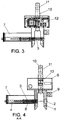
Figure 3 shows a profile view of the assembly in the previous figures. -
Figure 4 shows a similar view to the previous figure, but duly cross-sectioned along the cut line A-A infigure 2 . - Finally,
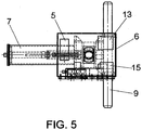
figure 5 shows a plan view of the device in the previous figures. - As can be seen in the summarised figures, the device of the invention consists of an inverted U-shaped bridge (1), with facing orifices (2), through which a pin (3) passes, to block the corresponding lug of the equipment to be lifted, said pin (3), driven by a pneumatic piston (4), housed in the corresponding cylindrical housing (7), which is supplied by a standalone compressor (5) integrated in the device itself, specifically in a housing (6) arranged above the bridge (1), where said mechanism is associated with a control circuit for actuation thereof via radio or manually by means of the corresponding safety push buttons placed on the device.
- As mentioned previously, a spring (8) associated with the arm of the pneumatic piston (4) is integrated into the pin (3) which performs its shock absorbing effect with three main functions, to guarantee that the movement of the pneumatic piston is always complete, making it impossible for the pin to remain mid-travel between the two support points on the structural bridge.
- This spring can be replaced by ring-type shock absorbers or any other type of commercial shock absorber.
- This shock absorbing system also has the function of ensuring and aiding alignment of the bridge and the part to be coupled and to protect against faults due to impact by the pin, and a system for thrust and alignment, both longitudinally and for support on the structural bridge, of said pin.
- Opposite the cylindrical housing (7), the bridge (1) has a handlebar (9) that provides for easy and convenient handling of the device if necessary.
- The bridge (1) is solidly connected at the upper end to a suspension shaft (10), with its corresponding lifting means (11), and integrated into which is a load cell (12), such that this element passes through the housing (6) in which the electronics for device control are housed.
- Housed in said housing (6) are at least one battery (12), one wireless communications module (13), and the control circuit (14) itself, in addition to the solenoid valves (15) to supply the pneumatic piston (4).
- In turn, the handlebar (9) includes a pair of push buttons (16) and (17) for the "dead man" system and for manual opening of the device.
- As mentioned previously, the device can be governed from the operator's own mobile phone, thanks to the wireless communications module, or it can have a remote control, which is not represented in the figures.
- Finally, the device includes indicator lamps (18, 19) which indicate open/closed and the battery status.
Claims (11)
- A lifting device for industrial equipment, which being for lifting any equipment fitted with at least one lifting lug, is characterised in that consists of an inverted U-shaped bridge (1), with facing orifices (2), through which passes a pin (3), driven by a pneumatic piston (4), housed in the corresponding cylindrical housing (7), which is supplied by a standalone compressor (5) established in a housing (6) arranged above the bridge (1), where said mechanism is associated with a control circuit for actuation thereof via radio or manually by means of the corresponding safety push buttons placed on the device, with the particular feature that the bridge (1) is solidly connected at the upper end to a suspension shaft (10), with its corresponding lifting means (11), and integrated into which is a load cell (12), such that said shaft passes through the housing (6) in which the electronics for device control are housed.
- A lifting device for industrial equipment, according to claim 1, characterised in that a spring (8) associated with the arm of the pneumatic piston (4) is integrated into the pin (3), serving as a shock absorber.
- A lifting device for industrial equipment, according to claim 2, characterised in that the spring (8) is capable of being replaced by ring-type shock absorbers or by any other type of commercial shock absorber.
- A lifting device for industrial equipment, according to claim 1, characterised in that, opposite the cylindrical housing (7), the bridge (1) has a handlebar (9) for manipulating the device.
- A lifting device for industrial equipment, according to claim 1, characterised in that housed in the core of the housing (6) are at least one battery (12), one wireless communications module (13), and the control circuit (14) itself, in addition to the solenoid valves (15) to supply the pneumatic piston (4).
- A lifting device for industrial equipment, according to claim 1, characterised in that the handlebar (9) includes a pair of push buttons (16) and (17) for the "dead man" system and for manual opening of the device.
- A lifting device for industrial equipment, according to claim 1, characterised in that it includes indicator lamps (18-19) which indicate open/closed and battery status.
- A lifting device for industrial equipment, according to claim 1, characterised in that it includes a load safety system for closing and opening, such that it is impossible to open the device if it is coupled to a suspended load.
- A lifting device for industrial equipment, according to claim 1, characterised in that it includes electrical systems for power control which register prohibited operations, giving rise to electrical blocking of the device, which is only reset by means of encrypted codes via radio.
- A lifting device for industrial equipment, according to claim 1, characterised in that it includes sensors such as limit switches, and open and closed sensors, as well as load presence sensors.
- A lifting device for industrial equipment, according to claim 1, characterised in that it incorporates an electronic starter key to enable energy saving when not in use, which is capable of being encoded.
Priority Applications (1)
| Application Number | Priority Date | Filing Date | Title |
|---|---|---|---|
| PL16813777T PL3312129T3 (en) | 2015-06-22 | 2016-04-26 | Lifting device for industrial equipment |
Applications Claiming Priority (2)
| Application Number | Priority Date | Filing Date | Title |
|---|---|---|---|
| ES201530883A ES2564878B1 (en) | 2015-06-22 | 2015-06-22 | INDUSTRIAL EQUIPMENT ELEVATION DEVICE |
| PCT/ES2016/070306 WO2016207457A1 (en) | 2015-06-22 | 2016-04-26 | Lifting device for industrial equipment |
Publications (3)
| Publication Number | Publication Date |
|---|---|
| EP3312129A1 true EP3312129A1 (en) | 2018-04-25 |
| EP3312129A4 EP3312129A4 (en) | 2019-02-20 |
| EP3312129B1 EP3312129B1 (en) | 2020-06-17 |
Family
ID=55537248
Family Applications (1)
| Application Number | Title | Priority Date | Filing Date |
|---|---|---|---|
| EP16813777.6A Active EP3312129B1 (en) | 2015-06-22 | 2016-04-26 | Lifting device for industrial equipment |
Country Status (4)
| Country | Link |
|---|---|
| EP (1) | EP3312129B1 (en) |
| ES (1) | ES2564878B1 (en) |
| PL (1) | PL3312129T3 (en) |
| WO (1) | WO2016207457A1 (en) |
Family Cites Families (14)
| Publication number | Priority date | Publication date | Assignee | Title |
|---|---|---|---|---|
| GB736525A (en) * | 1953-01-16 | 1955-09-07 | Fawcett Preston & Co Ltd | Improvements in or relating to load indicators and/or maximum load safety apparatus |
| GB903828A (en) * | 1959-12-21 | 1962-08-22 | British Steel Piling Co Ltd | Improvements in or relating to shackles |
| DE2728528A1 (en) * | 1977-06-24 | 1979-01-11 | Hubert Etter | Hoist load handling tackle - has open=ended housing lowered over load stirrup with movable locking pin |
| US4216987A (en) * | 1978-10-26 | 1980-08-12 | Ely Robert G | Safety shackle |
| US4573725A (en) * | 1984-04-02 | 1986-03-04 | Griffiths Edward E | Remote controlled crane hook coupler |
| NO300587B1 (en) * | 1995-06-08 | 1997-06-23 | Balmoral Norge As | Hydraulic shackle |
| NO964723L (en) * | 1996-11-07 | 1998-05-08 | Selantic As | Inverted accumulator |
| KR100261406B1 (en) * | 1997-10-23 | 2000-07-01 | 김재영 | Automatic opening closing type electric hook |
| US6303882B1 (en) * | 2000-03-10 | 2001-10-16 | Cranium Corporation | Load cell apparatus and method |
| KR100631434B1 (en) * | 2005-10-18 | 2006-10-09 | 황인규 | Auto open and close shackle assembly |
| CN102264627B (en) * | 2008-12-24 | 2013-09-18 | P&H有限公司 | Automated shackle assembly |
| EP2487103A1 (en) * | 2011-02-14 | 2012-08-15 | Selantic AS | Actuator apparatus |
| NO334555B1 (en) * | 2011-11-25 | 2014-04-07 | Lars Skjold | Underwater shackle for heavy loads |
| US9000311B1 (en) * | 2013-01-09 | 2015-04-07 | Jeff L. Collins | Crane scale anti-torque and protection housing |
-
2015
- 2015-06-22 ES ES201530883A patent/ES2564878B1/en active Active
-
2016
- 2016-04-26 WO PCT/ES2016/070306 patent/WO2016207457A1/en not_active Ceased
- 2016-04-26 PL PL16813777T patent/PL3312129T3/en unknown
- 2016-04-26 EP EP16813777.6A patent/EP3312129B1/en active Active
Also Published As
| Publication number | Publication date |
|---|---|
| ES2564878B1 (en) | 2017-11-08 |
| WO2016207457A1 (en) | 2016-12-29 |
| ES2564878A2 (en) | 2016-03-29 |
| EP3312129B1 (en) | 2020-06-17 |
| PL3312129T3 (en) | 2021-01-11 |
| EP3312129A4 (en) | 2019-02-20 |
| ES2564878R1 (en) | 2017-02-02 |
Similar Documents
| Publication | Publication Date | Title |
|---|---|---|
| JP2012508354A5 (en) | Valve position indicator, method of determining valve position and valve position display system | |
| CA2638325A1 (en) | Method and apparatus for providing diagnostics of a lifting magnet system | |
| US20160016764A1 (en) | Material lifting system and method | |
| CN109282643B (en) | Unmanned system for charging of ferronickel electric furnace top and control method | |
| EP3312129B1 (en) | Lifting device for industrial equipment | |
| US11042129B2 (en) | Redundant wireless safety system for manufacturing environment | |
| CN205114175U (en) | Container twistlock automatic unlocking device | |
| KR101797144B1 (en) | Crane hook with a safety device | |
| CN208327169U (en) | A kind of hoisting control system using magnechuck | |
| CN202175406U (en) | Work-piece transmission system | |
| CN204391550U (en) | A kind of remote assistant controls power distribution cabinet | |
| KR101914529B1 (en) | Operation control system for tower crane | |
| RU55760U1 (en) | CRANE REMOTE CONTROL SYSTEM (CDS) | |
| CN218025058U (en) | Monorail hoisting hanging beam for coal mine monorail crane | |
| CN110498164A (en) | The protection system of lift-on/lift-off type garbage truck safety work | |
| Sim et al. | The development of a robot hand for the automation of steel column construction | |
| CN107127774B (en) | Large-scale manipulator clip | |
| CN219906766U (en) | Electric remote control system of monorail crane remote control lifting device | |
| JP2021176670A (en) | Mobile pin drawing device | |
| NO20171367A1 (en) | System for controlling remotely controlled equipment | |
| CN201473125U (en) | Control device for a hoisting equipment and the hoisting equipment | |
| GB1583567A (en) | Remotecontrolled safety hook assembly | |
| CN204237453U (en) | Hoisting crane drop-gear box lubricating oil temperature safety monitoring assembly | |
| CN202164052U (en) | Automatic reset device responding to system halt of crane industrial wireless remote controller system | |
| CN121897778A (en) | Energy isolation intelligent lockset for rotary rod gate valve and valve switch monitoring method |
Legal Events
| Date | Code | Title | Description |
|---|---|---|---|
| STAA | Information on the status of an ep patent application or granted ep patent |
Free format text: STATUS: THE INTERNATIONAL PUBLICATION HAS BEEN MADE |
|
| PUAI | Public reference made under article 153(3) epc to a published international application that has entered the european phase |
Free format text: ORIGINAL CODE: 0009012 |
|
| STAA | Information on the status of an ep patent application or granted ep patent |
Free format text: STATUS: REQUEST FOR EXAMINATION WAS MADE |
|
| 17P | Request for examination filed |
Effective date: 20180122 |
|
| AK | Designated contracting states |
Kind code of ref document: A1 Designated state(s): AL AT BE BG CH CY CZ DE DK EE ES FI FR GB GR HR HU IE IS IT LI LT LU LV MC MK MT NL NO PL PT RO RS SE SI SK SM TR |
|
| AX | Request for extension of the european patent |
Extension state: BA ME |
|
| DAV | Request for validation of the european patent (deleted) | ||
| DAX | Request for extension of the european patent (deleted) | ||
| A4 | Supplementary search report drawn up and despatched |
Effective date: 20190123 |
|
| RIC1 | Information provided on ipc code assigned before grant |
Ipc: B66C 1/66 20060101ALI20190117BHEP Ipc: B66C 1/34 20060101ALI20190117BHEP Ipc: B66C 1/36 20060101ALI20190117BHEP Ipc: B66C 1/40 20060101AFI20190117BHEP |
|
| RIC1 | Information provided on ipc code assigned before grant |
Ipc: B66C 1/66 20060101ALI20191205BHEP Ipc: B66C 1/40 20060101AFI20191205BHEP Ipc: B66C 1/36 20060101ALI20191205BHEP Ipc: B66C 1/34 20060101ALI20191205BHEP |
|
| GRAP | Despatch of communication of intention to grant a patent |
Free format text: ORIGINAL CODE: EPIDOSNIGR1 |
|
| STAA | Information on the status of an ep patent application or granted ep patent |
Free format text: STATUS: GRANT OF PATENT IS INTENDED |
|
| INTG | Intention to grant announced |
Effective date: 20200113 |
|
| GRAS | Grant fee paid |
Free format text: ORIGINAL CODE: EPIDOSNIGR3 |
|
| GRAA | (expected) grant |
Free format text: ORIGINAL CODE: 0009210 |
|
| STAA | Information on the status of an ep patent application or granted ep patent |
Free format text: STATUS: THE PATENT HAS BEEN GRANTED |
|
| AK | Designated contracting states |
Kind code of ref document: B1 Designated state(s): AL AT BE BG CH CY CZ DE DK EE ES FI FR GB GR HR HU IE IS IT LI LT LU LV MC MK MT NL NO PL PT RO RS SE SI SK SM TR |
|
| REG | Reference to a national code |
Ref country code: GB Ref legal event code: FG4D |
|
| REG | Reference to a national code |
Ref country code: CH Ref legal event code: EP |
|
| REG | Reference to a national code |
Ref country code: IE Ref legal event code: FG4D |
|
| REG | Reference to a national code |
Ref country code: DE Ref legal event code: R096 Ref document number: 602016038399 Country of ref document: DE |
|
| REG | Reference to a national code |
Ref country code: AT Ref legal event code: REF Ref document number: 1281069 Country of ref document: AT Kind code of ref document: T Effective date: 20200715 |
|
| PG25 | Lapsed in a contracting state [announced via postgrant information from national office to epo] |
Ref country code: FI Free format text: LAPSE BECAUSE OF FAILURE TO SUBMIT A TRANSLATION OF THE DESCRIPTION OR TO PAY THE FEE WITHIN THE PRESCRIBED TIME-LIMIT Effective date: 20200617 Ref country code: SE Free format text: LAPSE BECAUSE OF FAILURE TO SUBMIT A TRANSLATION OF THE DESCRIPTION OR TO PAY THE FEE WITHIN THE PRESCRIBED TIME-LIMIT Effective date: 20200617 Ref country code: LT Free format text: LAPSE BECAUSE OF FAILURE TO SUBMIT A TRANSLATION OF THE DESCRIPTION OR TO PAY THE FEE WITHIN THE PRESCRIBED TIME-LIMIT Effective date: 20200617 Ref country code: NO Free format text: LAPSE BECAUSE OF FAILURE TO SUBMIT A TRANSLATION OF THE DESCRIPTION OR TO PAY THE FEE WITHIN THE PRESCRIBED TIME-LIMIT Effective date: 20200917 Ref country code: GR Free format text: LAPSE BECAUSE OF FAILURE TO SUBMIT A TRANSLATION OF THE DESCRIPTION OR TO PAY THE FEE WITHIN THE PRESCRIBED TIME-LIMIT Effective date: 20200918 |
|
| REG | Reference to a national code |
Ref country code: LT Ref legal event code: MG4D |
|
| REG | Reference to a national code |
Ref country code: NL Ref legal event code: MP Effective date: 20200617 |
|
| PG25 | Lapsed in a contracting state [announced via postgrant information from national office to epo] |
Ref country code: BG Free format text: LAPSE BECAUSE OF FAILURE TO SUBMIT A TRANSLATION OF THE DESCRIPTION OR TO PAY THE FEE WITHIN THE PRESCRIBED TIME-LIMIT Effective date: 20200917 Ref country code: RS Free format text: LAPSE BECAUSE OF FAILURE TO SUBMIT A TRANSLATION OF THE DESCRIPTION OR TO PAY THE FEE WITHIN THE PRESCRIBED TIME-LIMIT Effective date: 20200617 Ref country code: LV Free format text: LAPSE BECAUSE OF FAILURE TO SUBMIT A TRANSLATION OF THE DESCRIPTION OR TO PAY THE FEE WITHIN THE PRESCRIBED TIME-LIMIT Effective date: 20200617 Ref country code: HR Free format text: LAPSE BECAUSE OF FAILURE TO SUBMIT A TRANSLATION OF THE DESCRIPTION OR TO PAY THE FEE WITHIN THE PRESCRIBED TIME-LIMIT Effective date: 20200617 |
|
| REG | Reference to a national code |
Ref country code: AT Ref legal event code: MK05 Ref document number: 1281069 Country of ref document: AT Kind code of ref document: T Effective date: 20200617 |
|
| PG25 | Lapsed in a contracting state [announced via postgrant information from national office to epo] |
Ref country code: AL Free format text: LAPSE BECAUSE OF FAILURE TO SUBMIT A TRANSLATION OF THE DESCRIPTION OR TO PAY THE FEE WITHIN THE PRESCRIBED TIME-LIMIT Effective date: 20200617 Ref country code: NL Free format text: LAPSE BECAUSE OF FAILURE TO SUBMIT A TRANSLATION OF THE DESCRIPTION OR TO PAY THE FEE WITHIN THE PRESCRIBED TIME-LIMIT Effective date: 20200617 |
|
| PG25 | Lapsed in a contracting state [announced via postgrant information from national office to epo] |
Ref country code: AT Free format text: LAPSE BECAUSE OF FAILURE TO SUBMIT A TRANSLATION OF THE DESCRIPTION OR TO PAY THE FEE WITHIN THE PRESCRIBED TIME-LIMIT Effective date: 20200617 Ref country code: ES Free format text: LAPSE BECAUSE OF FAILURE TO SUBMIT A TRANSLATION OF THE DESCRIPTION OR TO PAY THE FEE WITHIN THE PRESCRIBED TIME-LIMIT Effective date: 20200617 Ref country code: SM Free format text: LAPSE BECAUSE OF FAILURE TO SUBMIT A TRANSLATION OF THE DESCRIPTION OR TO PAY THE FEE WITHIN THE PRESCRIBED TIME-LIMIT Effective date: 20200617 Ref country code: EE Free format text: LAPSE BECAUSE OF FAILURE TO SUBMIT A TRANSLATION OF THE DESCRIPTION OR TO PAY THE FEE WITHIN THE PRESCRIBED TIME-LIMIT Effective date: 20200617 Ref country code: IT Free format text: LAPSE BECAUSE OF FAILURE TO SUBMIT A TRANSLATION OF THE DESCRIPTION OR TO PAY THE FEE WITHIN THE PRESCRIBED TIME-LIMIT Effective date: 20200617 Ref country code: CZ Free format text: LAPSE BECAUSE OF FAILURE TO SUBMIT A TRANSLATION OF THE DESCRIPTION OR TO PAY THE FEE WITHIN THE PRESCRIBED TIME-LIMIT Effective date: 20200617 Ref country code: RO Free format text: LAPSE BECAUSE OF FAILURE TO SUBMIT A TRANSLATION OF THE DESCRIPTION OR TO PAY THE FEE WITHIN THE PRESCRIBED TIME-LIMIT Effective date: 20200617 Ref country code: PT Free format text: LAPSE BECAUSE OF FAILURE TO SUBMIT A TRANSLATION OF THE DESCRIPTION OR TO PAY THE FEE WITHIN THE PRESCRIBED TIME-LIMIT Effective date: 20201019 |
|
| PG25 | Lapsed in a contracting state [announced via postgrant information from national office to epo] |
Ref country code: SK Free format text: LAPSE BECAUSE OF FAILURE TO SUBMIT A TRANSLATION OF THE DESCRIPTION OR TO PAY THE FEE WITHIN THE PRESCRIBED TIME-LIMIT Effective date: 20200617 Ref country code: IS Free format text: LAPSE BECAUSE OF FAILURE TO SUBMIT A TRANSLATION OF THE DESCRIPTION OR TO PAY THE FEE WITHIN THE PRESCRIBED TIME-LIMIT Effective date: 20201017 |
|
| REG | Reference to a national code |
Ref country code: DE Ref legal event code: R097 Ref document number: 602016038399 Country of ref document: DE |
|
| PLBE | No opposition filed within time limit |
Free format text: ORIGINAL CODE: 0009261 |
|
| STAA | Information on the status of an ep patent application or granted ep patent |
Free format text: STATUS: NO OPPOSITION FILED WITHIN TIME LIMIT |
|
| PG25 | Lapsed in a contracting state [announced via postgrant information from national office to epo] |
Ref country code: DK Free format text: LAPSE BECAUSE OF FAILURE TO SUBMIT A TRANSLATION OF THE DESCRIPTION OR TO PAY THE FEE WITHIN THE PRESCRIBED TIME-LIMIT Effective date: 20200617 |
|
| 26N | No opposition filed |
Effective date: 20210318 |
|
| PG25 | Lapsed in a contracting state [announced via postgrant information from national office to epo] |
Ref country code: SI Free format text: LAPSE BECAUSE OF FAILURE TO SUBMIT A TRANSLATION OF THE DESCRIPTION OR TO PAY THE FEE WITHIN THE PRESCRIBED TIME-LIMIT Effective date: 20200617 |
|
| PG25 | Lapsed in a contracting state [announced via postgrant information from national office to epo] |
Ref country code: MC Free format text: LAPSE BECAUSE OF FAILURE TO SUBMIT A TRANSLATION OF THE DESCRIPTION OR TO PAY THE FEE WITHIN THE PRESCRIBED TIME-LIMIT Effective date: 20200617 |
|
| PG25 | Lapsed in a contracting state [announced via postgrant information from national office to epo] |
Ref country code: LU Free format text: LAPSE BECAUSE OF NON-PAYMENT OF DUE FEES Effective date: 20210426 |
|
| REG | Reference to a national code |
Ref country code: BE Ref legal event code: MM Effective date: 20210430 |
|
| PG25 | Lapsed in a contracting state [announced via postgrant information from national office to epo] |
Ref country code: CH Free format text: LAPSE BECAUSE OF NON-PAYMENT OF DUE FEES Effective date: 20210430 Ref country code: LI Free format text: LAPSE BECAUSE OF NON-PAYMENT OF DUE FEES Effective date: 20210430 |
|
| PG25 | Lapsed in a contracting state [announced via postgrant information from national office to epo] |
Ref country code: IE Free format text: LAPSE BECAUSE OF NON-PAYMENT OF DUE FEES Effective date: 20210426 |
|
| PG25 | Lapsed in a contracting state [announced via postgrant information from national office to epo] |
Ref country code: IS Free format text: LAPSE BECAUSE OF FAILURE TO SUBMIT A TRANSLATION OF THE DESCRIPTION OR TO PAY THE FEE WITHIN THE PRESCRIBED TIME-LIMIT Effective date: 20201017 |
|
| PG25 | Lapsed in a contracting state [announced via postgrant information from national office to epo] |
Ref country code: BE Free format text: LAPSE BECAUSE OF NON-PAYMENT OF DUE FEES Effective date: 20210430 |
|
| PG25 | Lapsed in a contracting state [announced via postgrant information from national office to epo] |
Ref country code: CY Free format text: LAPSE BECAUSE OF FAILURE TO SUBMIT A TRANSLATION OF THE DESCRIPTION OR TO PAY THE FEE WITHIN THE PRESCRIBED TIME-LIMIT Effective date: 20200617 |
|
| PG25 | Lapsed in a contracting state [announced via postgrant information from national office to epo] |
Ref country code: HU Free format text: LAPSE BECAUSE OF FAILURE TO SUBMIT A TRANSLATION OF THE DESCRIPTION OR TO PAY THE FEE WITHIN THE PRESCRIBED TIME-LIMIT; INVALID AB INITIO Effective date: 20160426 |
|
| PG25 | Lapsed in a contracting state [announced via postgrant information from national office to epo] |
Ref country code: MK Free format text: LAPSE BECAUSE OF FAILURE TO SUBMIT A TRANSLATION OF THE DESCRIPTION OR TO PAY THE FEE WITHIN THE PRESCRIBED TIME-LIMIT Effective date: 20200617 |
|
| PG25 | Lapsed in a contracting state [announced via postgrant information from national office to epo] |
Ref country code: TR Free format text: LAPSE BECAUSE OF FAILURE TO SUBMIT A TRANSLATION OF THE DESCRIPTION OR TO PAY THE FEE WITHIN THE PRESCRIBED TIME-LIMIT Effective date: 20200617 |
|
| PG25 | Lapsed in a contracting state [announced via postgrant information from national office to epo] |
Ref country code: MT Free format text: LAPSE BECAUSE OF FAILURE TO SUBMIT A TRANSLATION OF THE DESCRIPTION OR TO PAY THE FEE WITHIN THE PRESCRIBED TIME-LIMIT Effective date: 20200617 |
|
| PGFP | Annual fee paid to national office [announced via postgrant information from national office to epo] |
Ref country code: GB Payment date: 20260427 Year of fee payment: 11 Ref country code: PL Payment date: 20260422 Year of fee payment: 11 |
|
| PGFP | Annual fee paid to national office [announced via postgrant information from national office to epo] |
Ref country code: DE Payment date: 20260429 Year of fee payment: 11 |
|
| PGFP | Annual fee paid to national office [announced via postgrant information from national office to epo] |
Ref country code: FR Payment date: 20260427 Year of fee payment: 11 |