EP3312009A1 - Procédé et système d'inspection thermographique de pièces fabriquées de manière additive - Google Patents
Procédé et système d'inspection thermographique de pièces fabriquées de manière additive Download PDFInfo
- Publication number
- EP3312009A1 EP3312009A1 EP17196918.1A EP17196918A EP3312009A1 EP 3312009 A1 EP3312009 A1 EP 3312009A1 EP 17196918 A EP17196918 A EP 17196918A EP 3312009 A1 EP3312009 A1 EP 3312009A1
- Authority
- EP
- European Patent Office
- Prior art keywords
- manufacturing apparatus
- additive manufacturing
- heater
- build
- imaging device
- Prior art date
- Legal status (The legal status is an assumption and is not a legal conclusion. Google has not performed a legal analysis and makes no representation as to the accuracy of the status listed.)
- Withdrawn
Links
- 238000000034 method Methods 0.000 title claims abstract description 108
- 239000000654 additive Substances 0.000 title claims abstract description 86
- 230000000996 additive effect Effects 0.000 title claims abstract description 86
- 238000007689 inspection Methods 0.000 title claims abstract description 25
- 238000004519 manufacturing process Methods 0.000 claims abstract description 86
- 230000008569 process Effects 0.000 claims abstract description 53
- 230000007547 defect Effects 0.000 claims abstract description 45
- 238000010438 heat treatment Methods 0.000 claims abstract description 29
- 238000012544 monitoring process Methods 0.000 claims abstract description 14
- 238000003331 infrared imaging Methods 0.000 claims description 50
- 230000015654 memory Effects 0.000 claims description 24
- 238000003860 storage Methods 0.000 claims description 23
- 239000000843 powder Substances 0.000 claims description 21
- 238000004590 computer program Methods 0.000 claims description 16
- 239000000463 material Substances 0.000 claims description 14
- 230000004044 response Effects 0.000 claims description 13
- 238000011960 computer-aided design Methods 0.000 claims description 10
- 238000004891 communication Methods 0.000 claims description 9
- 230000004927 fusion Effects 0.000 claims description 8
- 230000006698 induction Effects 0.000 claims description 8
- XHCLAFWTIXFWPH-UHFFFAOYSA-N [O-2].[O-2].[O-2].[O-2].[O-2].[V+5].[V+5] Chemical compound [O-2].[O-2].[O-2].[O-2].[O-2].[V+5].[V+5] XHCLAFWTIXFWPH-UHFFFAOYSA-N 0.000 claims description 6
- 239000010453 quartz Substances 0.000 claims description 6
- VYPSYNLAJGMNEJ-UHFFFAOYSA-N silicon dioxide Inorganic materials O=[Si]=O VYPSYNLAJGMNEJ-UHFFFAOYSA-N 0.000 claims description 6
- 229910001935 vanadium oxide Inorganic materials 0.000 claims description 6
- 238000012423 maintenance Methods 0.000 claims description 5
- 230000003595 spectral effect Effects 0.000 claims description 5
- 230000007257 malfunction Effects 0.000 claims description 2
- 238000012545 processing Methods 0.000 description 27
- 238000007639 printing Methods 0.000 description 11
- 238000012360 testing method Methods 0.000 description 9
- 238000010586 diagram Methods 0.000 description 8
- 238000002844 melting Methods 0.000 description 8
- 230000008018 melting Effects 0.000 description 8
- 230000008901 benefit Effects 0.000 description 7
- 238000004422 calculation algorithm Methods 0.000 description 7
- 238000011156 evaluation Methods 0.000 description 7
- 230000006870 function Effects 0.000 description 6
- 230000001052 transient effect Effects 0.000 description 6
- 238000010146 3D printing Methods 0.000 description 4
- 230000009471 action Effects 0.000 description 4
- 230000006399 behavior Effects 0.000 description 4
- 238000013461 design Methods 0.000 description 4
- 238000005516 engineering process Methods 0.000 description 4
- 230000005291 magnetic effect Effects 0.000 description 4
- 229910052751 metal Inorganic materials 0.000 description 4
- 239000002184 metal Substances 0.000 description 4
- 238000009659 non-destructive testing Methods 0.000 description 4
- 230000003287 optical effect Effects 0.000 description 4
- 238000000110 selective laser sintering Methods 0.000 description 4
- 238000001931 thermography Methods 0.000 description 4
- 239000011800 void material Substances 0.000 description 4
- 230000032798 delamination Effects 0.000 description 3
- 230000036541 health Effects 0.000 description 3
- 238000002329 infrared spectrum Methods 0.000 description 3
- 238000012986 modification Methods 0.000 description 3
- 230000004048 modification Effects 0.000 description 3
- 239000013307 optical fiber Substances 0.000 description 3
- 238000002310 reflectometry Methods 0.000 description 3
- 238000013179 statistical model Methods 0.000 description 3
- 238000004458 analytical method Methods 0.000 description 2
- 238000000149 argon plasma sintering Methods 0.000 description 2
- 238000013528 artificial neural network Methods 0.000 description 2
- 239000002131 composite material Substances 0.000 description 2
- 238000002591 computed tomography Methods 0.000 description 2
- 238000005336 cracking Methods 0.000 description 2
- 230000002950 deficient Effects 0.000 description 2
- 230000001419 dependent effect Effects 0.000 description 2
- 230000008021 deposition Effects 0.000 description 2
- 238000001514 detection method Methods 0.000 description 2
- 238000009826 distribution Methods 0.000 description 2
- 238000010894 electron beam technology Methods 0.000 description 2
- 238000003384 imaging method Methods 0.000 description 2
- 238000010801 machine learning Methods 0.000 description 2
- 238000003908 quality control method Methods 0.000 description 2
- 230000000717 retained effect Effects 0.000 description 2
- 230000035945 sensitivity Effects 0.000 description 2
- 238000005245 sintering Methods 0.000 description 2
- 238000012549 training Methods 0.000 description 2
- 238000002604 ultrasonography Methods 0.000 description 2
- 230000005856 abnormality Effects 0.000 description 1
- 230000004075 alteration Effects 0.000 description 1
- 238000013459 approach Methods 0.000 description 1
- 238000004364 calculation method Methods 0.000 description 1
- 238000005266 casting Methods 0.000 description 1
- 239000011365 complex material Substances 0.000 description 1
- 238000013144 data compression Methods 0.000 description 1
- 239000003302 ferromagnetic material Substances 0.000 description 1
- 238000003754 machining Methods 0.000 description 1
- 239000007769 metal material Substances 0.000 description 1
- 239000000203 mixture Substances 0.000 description 1
- 238000012805 post-processing Methods 0.000 description 1
- 238000004886 process control Methods 0.000 description 1
- 230000002250 progressing effect Effects 0.000 description 1
- 238000000275 quality assurance Methods 0.000 description 1
- 238000010223 real-time analysis Methods 0.000 description 1
- 230000000246 remedial effect Effects 0.000 description 1
- 230000002441 reversible effect Effects 0.000 description 1
- 238000005070 sampling Methods 0.000 description 1
- 239000004065 semiconductor Substances 0.000 description 1
- 238000004513 sizing Methods 0.000 description 1
- 238000006467 substitution reaction Methods 0.000 description 1
- 238000001757 thermogravimetry curve Methods 0.000 description 1
Images


Classifications
-
- B—PERFORMING OPERATIONS; TRANSPORTING
- B29—WORKING OF PLASTICS; WORKING OF SUBSTANCES IN A PLASTIC STATE IN GENERAL
- B29C—SHAPING OR JOINING OF PLASTICS; SHAPING OF MATERIAL IN A PLASTIC STATE, NOT OTHERWISE PROVIDED FOR; AFTER-TREATMENT OF THE SHAPED PRODUCTS, e.g. REPAIRING
- B29C64/00—Additive manufacturing, i.e. manufacturing of three-dimensional [3D] objects by additive deposition, additive agglomeration or additive layering, e.g. by 3D printing, stereolithography or selective laser sintering
- B29C64/10—Processes of additive manufacturing
-
- B—PERFORMING OPERATIONS; TRANSPORTING
- B22—CASTING; POWDER METALLURGY
- B22F—WORKING METALLIC POWDER; MANUFACTURE OF ARTICLES FROM METALLIC POWDER; MAKING METALLIC POWDER; APPARATUS OR DEVICES SPECIALLY ADAPTED FOR METALLIC POWDER
- B22F10/00—Additive manufacturing of workpieces or articles from metallic powder
- B22F10/20—Direct sintering or melting
- B22F10/28—Powder bed fusion, e.g. selective laser melting [SLM] or electron beam melting [EBM]
-
- B—PERFORMING OPERATIONS; TRANSPORTING
- B22—CASTING; POWDER METALLURGY
- B22F—WORKING METALLIC POWDER; MANUFACTURE OF ARTICLES FROM METALLIC POWDER; MAKING METALLIC POWDER; APPARATUS OR DEVICES SPECIALLY ADAPTED FOR METALLIC POWDER
- B22F10/00—Additive manufacturing of workpieces or articles from metallic powder
- B22F10/30—Process control
- B22F10/31—Calibration of process steps or apparatus settings, e.g. before or during manufacturing
-
- B—PERFORMING OPERATIONS; TRANSPORTING
- B22—CASTING; POWDER METALLURGY
- B22F—WORKING METALLIC POWDER; MANUFACTURE OF ARTICLES FROM METALLIC POWDER; MAKING METALLIC POWDER; APPARATUS OR DEVICES SPECIALLY ADAPTED FOR METALLIC POWDER
- B22F10/00—Additive manufacturing of workpieces or articles from metallic powder
- B22F10/30—Process control
- B22F10/36—Process control of energy beam parameters
-
- B—PERFORMING OPERATIONS; TRANSPORTING
- B22—CASTING; POWDER METALLURGY
- B22F—WORKING METALLIC POWDER; MANUFACTURE OF ARTICLES FROM METALLIC POWDER; MAKING METALLIC POWDER; APPARATUS OR DEVICES SPECIALLY ADAPTED FOR METALLIC POWDER
- B22F10/00—Additive manufacturing of workpieces or articles from metallic powder
- B22F10/30—Process control
- B22F10/38—Process control to achieve specific product aspects, e.g. surface smoothness, density, porosity or hollow structures
-
- B—PERFORMING OPERATIONS; TRANSPORTING
- B22—CASTING; POWDER METALLURGY
- B22F—WORKING METALLIC POWDER; MANUFACTURE OF ARTICLES FROM METALLIC POWDER; MAKING METALLIC POWDER; APPARATUS OR DEVICES SPECIALLY ADAPTED FOR METALLIC POWDER
- B22F10/00—Additive manufacturing of workpieces or articles from metallic powder
- B22F10/80—Data acquisition or data processing
- B22F10/85—Data acquisition or data processing for controlling or regulating additive manufacturing processes
-
- B—PERFORMING OPERATIONS; TRANSPORTING
- B22—CASTING; POWDER METALLURGY
- B22F—WORKING METALLIC POWDER; MANUFACTURE OF ARTICLES FROM METALLIC POWDER; MAKING METALLIC POWDER; APPARATUS OR DEVICES SPECIALLY ADAPTED FOR METALLIC POWDER
- B22F12/00—Apparatus or devices specially adapted for additive manufacturing; Auxiliary means for additive manufacturing; Combinations of additive manufacturing apparatus or devices with other processing apparatus or devices
- B22F12/10—Auxiliary heating means
- B22F12/17—Auxiliary heating means to heat the build chamber or platform
-
- B—PERFORMING OPERATIONS; TRANSPORTING
- B22—CASTING; POWDER METALLURGY
- B22F—WORKING METALLIC POWDER; MANUFACTURE OF ARTICLES FROM METALLIC POWDER; MAKING METALLIC POWDER; APPARATUS OR DEVICES SPECIALLY ADAPTED FOR METALLIC POWDER
- B22F12/00—Apparatus or devices specially adapted for additive manufacturing; Auxiliary means for additive manufacturing; Combinations of additive manufacturing apparatus or devices with other processing apparatus or devices
- B22F12/90—Means for process control, e.g. cameras or sensors
-
- B—PERFORMING OPERATIONS; TRANSPORTING
- B22—CASTING; POWDER METALLURGY
- B22F—WORKING METALLIC POWDER; MANUFACTURE OF ARTICLES FROM METALLIC POWDER; MAKING METALLIC POWDER; APPARATUS OR DEVICES SPECIALLY ADAPTED FOR METALLIC POWDER
- B22F3/00—Manufacture of workpieces or articles from metallic powder characterised by the manner of compacting or sintering; Apparatus specially adapted therefor ; Presses and furnaces
- B22F3/10—Sintering only
- B22F3/1017—Multiple heating or additional steps
-
- B—PERFORMING OPERATIONS; TRANSPORTING
- B29—WORKING OF PLASTICS; WORKING OF SUBSTANCES IN A PLASTIC STATE IN GENERAL
- B29C—SHAPING OR JOINING OF PLASTICS; SHAPING OF MATERIAL IN A PLASTIC STATE, NOT OTHERWISE PROVIDED FOR; AFTER-TREATMENT OF THE SHAPED PRODUCTS, e.g. REPAIRING
- B29C64/00—Additive manufacturing, i.e. manufacturing of three-dimensional [3D] objects by additive deposition, additive agglomeration or additive layering, e.g. by 3D printing, stereolithography or selective laser sintering
- B29C64/20—Apparatus for additive manufacturing; Details thereof or accessories therefor
- B29C64/295—Heating elements
-
- B—PERFORMING OPERATIONS; TRANSPORTING
- B29—WORKING OF PLASTICS; WORKING OF SUBSTANCES IN A PLASTIC STATE IN GENERAL
- B29C—SHAPING OR JOINING OF PLASTICS; SHAPING OF MATERIAL IN A PLASTIC STATE, NOT OTHERWISE PROVIDED FOR; AFTER-TREATMENT OF THE SHAPED PRODUCTS, e.g. REPAIRING
- B29C64/00—Additive manufacturing, i.e. manufacturing of three-dimensional [3D] objects by additive deposition, additive agglomeration or additive layering, e.g. by 3D printing, stereolithography or selective laser sintering
- B29C64/30—Auxiliary operations or equipment
- B29C64/386—Data acquisition or data processing for additive manufacturing
- B29C64/393—Data acquisition or data processing for additive manufacturing for controlling or regulating additive manufacturing processes
-
- B—PERFORMING OPERATIONS; TRANSPORTING
- B33—ADDITIVE MANUFACTURING TECHNOLOGY
- B33Y—ADDITIVE MANUFACTURING, i.e. MANUFACTURING OF THREE-DIMENSIONAL [3-D] OBJECTS BY ADDITIVE DEPOSITION, ADDITIVE AGGLOMERATION OR ADDITIVE LAYERING, e.g. BY 3-D PRINTING, STEREOLITHOGRAPHY OR SELECTIVE LASER SINTERING
- B33Y10/00—Processes of additive manufacturing
-
- B—PERFORMING OPERATIONS; TRANSPORTING
- B33—ADDITIVE MANUFACTURING TECHNOLOGY
- B33Y—ADDITIVE MANUFACTURING, i.e. MANUFACTURING OF THREE-DIMENSIONAL [3-D] OBJECTS BY ADDITIVE DEPOSITION, ADDITIVE AGGLOMERATION OR ADDITIVE LAYERING, e.g. BY 3-D PRINTING, STEREOLITHOGRAPHY OR SELECTIVE LASER SINTERING
- B33Y30/00—Apparatus for additive manufacturing; Details thereof or accessories therefor
-
- B—PERFORMING OPERATIONS; TRANSPORTING
- B33—ADDITIVE MANUFACTURING TECHNOLOGY
- B33Y—ADDITIVE MANUFACTURING, i.e. MANUFACTURING OF THREE-DIMENSIONAL [3-D] OBJECTS BY ADDITIVE DEPOSITION, ADDITIVE AGGLOMERATION OR ADDITIVE LAYERING, e.g. BY 3-D PRINTING, STEREOLITHOGRAPHY OR SELECTIVE LASER SINTERING
- B33Y50/00—Data acquisition or data processing for additive manufacturing
- B33Y50/02—Data acquisition or data processing for additive manufacturing for controlling or regulating additive manufacturing processes
-
- G—PHYSICS
- G01—MEASURING; TESTING
- G01J—MEASUREMENT OF INTENSITY, VELOCITY, SPECTRAL CONTENT, POLARISATION, PHASE OR PULSE CHARACTERISTICS OF INFRARED, VISIBLE OR ULTRAVIOLET LIGHT; COLORIMETRY; RADIATION PYROMETRY
- G01J5/00—Radiation pyrometry, e.g. infrared or optical thermometry
- G01J5/0037—Radiation pyrometry, e.g. infrared or optical thermometry for sensing the heat emitted by liquids
- G01J5/004—Radiation pyrometry, e.g. infrared or optical thermometry for sensing the heat emitted by liquids by molten metals
-
- G—PHYSICS
- G01—MEASURING; TESTING
- G01J—MEASUREMENT OF INTENSITY, VELOCITY, SPECTRAL CONTENT, POLARISATION, PHASE OR PULSE CHARACTERISTICS OF INFRARED, VISIBLE OR ULTRAVIOLET LIGHT; COLORIMETRY; RADIATION PYROMETRY
- G01J5/00—Radiation pyrometry, e.g. infrared or optical thermometry
- G01J5/10—Radiation pyrometry, e.g. infrared or optical thermometry using electric radiation detectors
-
- G—PHYSICS
- G01—MEASURING; TESTING
- G01J—MEASUREMENT OF INTENSITY, VELOCITY, SPECTRAL CONTENT, POLARISATION, PHASE OR PULSE CHARACTERISTICS OF INFRARED, VISIBLE OR ULTRAVIOLET LIGHT; COLORIMETRY; RADIATION PYROMETRY
- G01J5/00—Radiation pyrometry, e.g. infrared or optical thermometry
- G01J5/48—Thermography; Techniques using wholly visual means
-
- G—PHYSICS
- G01—MEASURING; TESTING
- G01J—MEASUREMENT OF INTENSITY, VELOCITY, SPECTRAL CONTENT, POLARISATION, PHASE OR PULSE CHARACTERISTICS OF INFRARED, VISIBLE OR ULTRAVIOLET LIGHT; COLORIMETRY; RADIATION PYROMETRY
- G01J5/00—Radiation pyrometry, e.g. infrared or optical thermometry
- G01J5/80—Calibration
-
- G—PHYSICS
- G01—MEASURING; TESTING
- G01N—INVESTIGATING OR ANALYSING MATERIALS BY DETERMINING THEIR CHEMICAL OR PHYSICAL PROPERTIES
- G01N25/00—Investigating or analyzing materials by the use of thermal means
- G01N25/72—Investigating presence of flaws
-
- B—PERFORMING OPERATIONS; TRANSPORTING
- B22—CASTING; POWDER METALLURGY
- B22F—WORKING METALLIC POWDER; MANUFACTURE OF ARTICLES FROM METALLIC POWDER; MAKING METALLIC POWDER; APPARATUS OR DEVICES SPECIALLY ADAPTED FOR METALLIC POWDER
- B22F10/00—Additive manufacturing of workpieces or articles from metallic powder
- B22F10/10—Formation of a green body
- B22F10/12—Formation of a green body by photopolymerisation, e.g. stereolithography [SLA] or digital light processing [DLP]
-
- B—PERFORMING OPERATIONS; TRANSPORTING
- B22—CASTING; POWDER METALLURGY
- B22F—WORKING METALLIC POWDER; MANUFACTURE OF ARTICLES FROM METALLIC POWDER; MAKING METALLIC POWDER; APPARATUS OR DEVICES SPECIALLY ADAPTED FOR METALLIC POWDER
- B22F10/00—Additive manufacturing of workpieces or articles from metallic powder
- B22F10/10—Formation of a green body
- B22F10/18—Formation of a green body by mixing binder with metal in filament form, e.g. fused filament fabrication [FFF]
-
- B—PERFORMING OPERATIONS; TRANSPORTING
- B22—CASTING; POWDER METALLURGY
- B22F—WORKING METALLIC POWDER; MANUFACTURE OF ARTICLES FROM METALLIC POWDER; MAKING METALLIC POWDER; APPARATUS OR DEVICES SPECIALLY ADAPTED FOR METALLIC POWDER
- B22F3/00—Manufacture of workpieces or articles from metallic powder characterised by the manner of compacting or sintering; Apparatus specially adapted therefor ; Presses and furnaces
- B22F3/10—Sintering only
- B22F3/105—Sintering only by using electric current other than for infrared radiant energy, laser radiation or plasma ; by ultrasonic bonding
- B22F2003/1053—Sintering only by using electric current other than for infrared radiant energy, laser radiation or plasma ; by ultrasonic bonding by induction
-
- B—PERFORMING OPERATIONS; TRANSPORTING
- B22—CASTING; POWDER METALLURGY
- B22F—WORKING METALLIC POWDER; MANUFACTURE OF ARTICLES FROM METALLIC POWDER; MAKING METALLIC POWDER; APPARATUS OR DEVICES SPECIALLY ADAPTED FOR METALLIC POWDER
- B22F3/00—Manufacture of workpieces or articles from metallic powder characterised by the manner of compacting or sintering; Apparatus specially adapted therefor ; Presses and furnaces
- B22F3/10—Sintering only
- B22F3/105—Sintering only by using electric current other than for infrared radiant energy, laser radiation or plasma ; by ultrasonic bonding
- B22F2003/1054—Sintering only by using electric current other than for infrared radiant energy, laser radiation or plasma ; by ultrasonic bonding by microwave
-
- B—PERFORMING OPERATIONS; TRANSPORTING
- B22—CASTING; POWDER METALLURGY
- B22F—WORKING METALLIC POWDER; MANUFACTURE OF ARTICLES FROM METALLIC POWDER; MAKING METALLIC POWDER; APPARATUS OR DEVICES SPECIALLY ADAPTED FOR METALLIC POWDER
- B22F2998/00—Supplementary information concerning processes or compositions relating to powder metallurgy
- B22F2998/10—Processes characterised by the sequence of their steps
-
- G—PHYSICS
- G01—MEASURING; TESTING
- G01J—MEASUREMENT OF INTENSITY, VELOCITY, SPECTRAL CONTENT, POLARISATION, PHASE OR PULSE CHARACTERISTICS OF INFRARED, VISIBLE OR ULTRAVIOLET LIGHT; COLORIMETRY; RADIATION PYROMETRY
- G01J5/00—Radiation pyrometry, e.g. infrared or optical thermometry
- G01J2005/0077—Imaging
-
- Y—GENERAL TAGGING OF NEW TECHNOLOGICAL DEVELOPMENTS; GENERAL TAGGING OF CROSS-SECTIONAL TECHNOLOGIES SPANNING OVER SEVERAL SECTIONS OF THE IPC; TECHNICAL SUBJECTS COVERED BY FORMER USPC CROSS-REFERENCE ART COLLECTIONS [XRACs] AND DIGESTS
- Y02—TECHNOLOGIES OR APPLICATIONS FOR MITIGATION OR ADAPTATION AGAINST CLIMATE CHANGE
- Y02P—CLIMATE CHANGE MITIGATION TECHNOLOGIES IN THE PRODUCTION OR PROCESSING OF GOODS
- Y02P10/00—Technologies related to metal processing
- Y02P10/25—Process efficiency
Definitions
- Additive manufacturing is a process by which a three-dimensional structure is built, usually in a series of layers, based on a digital model of the structure.
- the process is sometimes referred to as three-dimensional (3D) printing or 3D rapid prototyping, and the term "print” is often used even though some examples of the technology rely on sintering or melting/fusing by way of an energy source to form the structure, rather than "printing" in the traditional sense where material is deposited at select locations.
- additive manufacturing techniques include powder bed fusion, fused deposition modeling, electron beam melting (EBM), laminated object manufacturing, selective laser sintering (SLS), direct metal laser sintering (DMLS), direct metal laser melting (DMLM), selective laser melting (SLM), and stereolithography, among others.
- EBM electron beam melting
- SLS selective laser sintering
- DMLS direct metal laser sintering
- DMLM direct metal laser melting
- SLM selective laser melting
- stereolithography among others.
- One of the disadvantages of current additive manufacturing processing relates to quality assurance. There is typically some amount of analysis to determine whether the produced part meets the manufacturing thresholds and design criteria. In some examples, the part may have to be dissected in order to test whether a certain lot of products or a sampling has satisfied the design limits. This can lead to considerable inefficiency when, for example, it is later determined that a production lot is defective due to a machining or design problem.
- a method for inspection of additive manufactured parts and monitoring operational performance of an additive manufacturing apparatus includes a heating step for heating an area of a build platform on which at least one part is built by the additive manufacturing apparatus.
- An obtaining step is used for obtaining, in real-time during an additively manufactured build process, a thermographic scan of the area of the build platform.
- An evaluating step evaluates, by a processor, the thermographic scan.
- a determining step determines, based on the evaluating, whether an operational flaw with the additive manufacturing apparatus has occurred or a defect in the at least one part has occurred.
- a system for inspection of additive manufactured parts and monitoring operational performance of an additive manufacturing apparatus.
- the system includes a heater, an infrared imaging device, a memory and a processor in communication with the memory.
- the system is configured to perform a heating step that heats with the heater an area of a build platform on which at least one part is built by the additive manufacturing apparatus.
- An obtaining step obtains with the infrared imaging device, in real-time during an additively manufactured build process, a thermographic scan of the area of the build platform and/or of the part(s).
- An evaluating step evaluates, by the processor, the thermographic scan.
- a determining step determines, based on the evaluating, whether an operational flaw with the additive manufacturing apparatus has occurred, or if a defect in the at least one part has occurred.
- a computer program product for inspection of additive manufactured parts and monitoring operational performance of an additive manufacturing apparatus.
- the computer program product includes a non-transitory computer readable storage medium readable by a processor and storing instructions for execution by the process to perform a method.
- the method includes a heating step that heats with a heater an area of a build platform on which at least one part is built by the additive manufacturing apparatus.
- An obtaining step obtains with an infrared imaging device, in real-time during an additively manufactured build process, a thermographic scan of the area of the build platform or of the part(s).
- An evaluating step evaluates, by the processor, the thermographic scan.
- a determining step determines, based on the evaluating, whether an operational flaw with the additive manufacturing apparatus has occurred or a defect in the at least one part has occurred.
- additive manufacturing apparatus is used interchangeably herein with the phrase “printing apparatus” and term “printer”, and the term “print” is used interchangeably herein with the word “build”, referring to the action for building a structure by an additive manufacturing apparatus, regardless of the particular additive manufacturing technology being used to form the structure.
- structure and “part” are also used interchangeably, and both terms refer to an additively manufactured physical object (e.g., a machine part, a tool, or etc.).
- print and printing refer to the various forms of additive manufacturing and include three-dimensional (3D) printing or 3D rapid prototyping, as well as sintering or melting/fusing technologies.
- additive manufacturing or printing techniques include powder bed fusion, fused deposition modeling, electron beam melting (EBM), laminated object manufacturing, selective laser sintering (SLS), direct metal laser sintering (DMLS), direct metal laser melting (DMLM), selective laser melting (SLM), and stereolithography, among others.
- EBM electron beam melting
- SLS selective laser sintering
- DMLS direct metal laser sintering
- DMLM direct metal laser melting
- SLM selective laser melting
- stereolithography stereolithography
- Assurance that a build process is progressing as planned is important for cost and quality reasons.
- an operator of the additive manufacturing apparatus may find that the parts are defective or unusable because of a failure with the additive manufacturing apparatus during the build cycle. This can be especially problematic when building expensive parts, such as molds for casting structures having complex geometries.
- thermographic scanning system and method are disclosed herein that may be used to monitor the building of layers of one or more objects being built by an additive manufacturing apparatus, and, in one embodiment, to detect operational flaws as they occur, (i.e. during the build process rather than afterward, as an example).
- evaluation/analysis of thermographic scans acquired during the build process is performed as part of post-processing (and not as part of the real-time acquisition of scanned data).
- Real-time acquisition refers to the scans of individual layer(s) of the structure as the structure is being built ("printed").
- Real-time analysis refers to evaluation of the acquired thermographic scans of the various layers.
- Operational flaws may include, as examples, errors with the part(s), build process, or additive manufacturing apparatus, or indicators that one or more errors are likely to occur with the part(s), build process, or additive manufacturing apparatus, or lack of fusion, porosity or micro/macro cracks.
- action(s) may be taken responsive to observing that an operational flaw has occurred. For instance, remedial actions may be taken so that the flaw can be corrected, the build process stopped, the problem fixed, a new build started, etc. In other cases, a flaw may be detected but is determined to be insignificant, therefore the build process may continue.
- Thermographic inspection is the nondestructive testing of objects through imaging of thermal patterns on the object's surface.
- Thermographic inspection is often preferred to other nondestructive testing techniques such as ultrasonic inspection and radiographic inspection, for various advantages offered by thermographic inspection.
- Thermographic inspection is non-contact, non-intrusive, allows for detection of subsurface detects close to the surface, allows for inspection of large surfaces, and offers high speed inspection.
- One form of thermographic inspection is transient thermography. Transient thermography involves observing the temperature distribution on the surface of an object under test as it is subjected to a thermal transient such as a pulse of heat or a pulse of heat sink, and then allowed to return to ambient temperature. Any flaws present are detected as abnormalities in the surface temperature distribution during this thermal transient. Transient thermography is particularly well suited to the inspection of composite materials. The relatively low thermal conductivity of composite materials results in relatively long-lived thermal transients, therefore making the thermal transient easy to detect with a thermal camera.
- thermographic inspection techniques are operator dependent techniques, involving an operator to watch a thermal video of the object under test. The operator then observes the video for changes in contrast caused due to flaws within the object. Such techniques are skill intensive and require much manual effort.
- Automated thermographic inspection techniques use a heat source such as a high intensity flash lamp to heat the surface of an object under test.
- An infrared camera then takes a series of thermal images or thermograms of the object under test. The images are then post processed to identify features in the object under test.
- thermographically observe a build process that may take hours or days to complete in order to detect and react to potential operational flaws with the additive manufacturing apparatus and/or errors with one or more printed layers. Also provided is the ability to communicate indications of the operational flaws to operators early in the build process as, or before, they occur, so that a failed build can be stopped prior to its completion. A new build may then be started earlier than it otherwise would have been (i.e. had the failure been discovered only after the failed build process completes). From a manufacturing resources perspective, wasted materials usage and wasted build time are reduced.
- Some problems that may be observed during the monitoring of a build process as described herein include, but are not limited to, dimensional errors, distortion, lack of fusion, porosity, micro cracking or macro cracking in the printed structures, malfunctioning of a roller/planarizer or other component of the printing apparatus, poor layer surface finish, delamination of the structures, misplacement, excess, or absence of build material, or any other additive manufacturing errors.
- the monitoring can monitor for anything that can cause the built part to fail or that can indicate that that additive manufacturing apparatus has failed, is about to fail, or needs maintenance, as examples.
- FIGS. 1-9 An example additive manufacturing apparatus and associated process in accordance with aspects described herein are presented with reference to FIGS. 1-9 , in the context of printed parts.
- the parts in this example are built out of printed metallic or ferro-magnetic material, though other materials are possible.
- FIG. 1 depicts one example of an additive manufacturing apparatus, in accordance with aspects described herein.
- printing apparatus 100 is a powder bed fusion type of 3D printing device that includes a laser 102 and lens 104.
- a build section 110 is located adjacent to a dispensing section 120.
- the build section includes the build platform 112, onto which the part 140 (e.g., the 3D printed part or structure) is built.
- the build platform is connected to a shaft or support 113 that lowers the build platform in increments as the part 140 is built.
- the build platform will be at a high position, and as each layer of the part 140 is formed the build platform will lower accordingly.
- the build platform 112 or build section 110 is enclosed on the sides by walls 114 and 116 (additional walls may be used, but are not shown).
- the dispensing section 120 contains a supply of powder 130 supported by dispensing platform 122 and contained by walls 116 and 123.
- the dispensing platform 122 is raised up by shaft or support 124.
- the dispensing platform 122 will raise up by a predetermined amount so that recoating blade 150 can push the powder 130 from section 120 over to section 110.
- a new layer of powder is spread over part 140 so that the laser 102 may fuse the next layer of the part 140.
- the recoating blade 150 will then return to its position above wall 123, and be ready for the next layer.
- an infrared imaging device 160 is provided to thermographically image or scan the upper layers of the build platform and part(s) 140.
- a heater 165 is also provided and is configured for heating the upper surface build platform and/or the upper layers of part 140.
- the infrared imaging device 160 may be an infrared camera, a focal plane array infrared sensor, a vanadium oxide microbolometer array sensor or any other suitable device for capturing thermographic images in the infrared spectrum.
- the heater 165 may be a flash lamp, high intensity discharge tube flash unit, infrared lamp, a quartz lamp, a microwave tube, or the like. As will be described later, the heater may also be an induction heating unit or an ultrasonic heater.
- the heater 165 discharges a high intensity but short lived pulse of heat towards the top layer of the part 140. This heat is absorbed and then radiated towards the infrared imaging device 160. The infrared imaging device 160 then captures an image of this reflected heat pulse and the resulting image can be processed, evaluated and then a determination may be made as to the presence or absence of defects in part 140.
- the heater 165 may also comprise a plurality of heaters arranged symmetrically above the build platform as shown.
- One or more calibration blocks 170 may be located on walls 114, 116 or on the build platform (not shown) to calibrate the infrared imaging device 160 prior to a scan operation.
- the calibration block(s) 170 are configured to be scanned by infrared imaging device 160 by being placed within the field of view of the device 160.
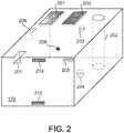
- the calibration block 170 may have different known artificial defects such as holes, notches, delamination, and voids that represent actual defects that can happen during the printing/build process. Referring to FIG. 2 , a calibration block 170 is shown having various known defects and calibration areas.
- the known artificial defects may include a notch 201, hole 202, voids 203, 204, area of delamination 205, and inclusion 206.
- Calibration areas may include areas with known thermal characteristics, such as surface 207 with known reflectivity and emissivity, area 208 of the same material as the powder with known thickness close to the desired layer thickness, blackbody area/surface 209. Further, thermometers 210 may be located at different locations on the calibration block to measure the absolute temperature. Many different critical values such as reflectivity, emissivity and etc. can be measured using the designed calibration block of FIG. 2 . Furthermore, the infrared imaging device 160 can be calibrated by first scanning the calibration block and comparing the result with a known good scan of the calibration block. If there are discrepancies beyond a predetermined threshold, then the device 160 response can be adjusted to normal expectations. Calibration can be done before every scan or after a selected number of scans.
- FIG. 3 illustrates a side, cross-sectional view of a system, in accordance with aspects described herein.
- the heating is accomplished by an induction heating unit 301.
- the coils of the induction heating unit may be embedded in the walls 114, 116 or placed above the build platform and around part 140. As the coils are energized (typically with an alternating current at different frequencies) eddy currents are formed within part 140. These eddy currents generate heat and the heat can be detected by infrared imaging device 160.
- FIG. 4 illustrates a side, cross-sectional view of a system, in accordance with aspects described herein.
- the heating is accomplished by an ultrasonic vibration heater 410.
- the heater 410 includes an applicator 412 and ultrasonic vibrations induce thermal emissions from part 140.
- the thermal emissions from part 140 are captured by infrared imaging device 160.
- the applicator 412 may be disposed on an extendable arm (not shown), so that it can be retracted away from the build section and deployed over the build section as desired.
- ultrasound may be generated in the part 140 from an applicator 413 in or on the platform 112.
- Elastic waves will propagate in the part 140 and in case of internal flaws, such as cracks, the boundary faces move relative to each other (i.e. crack on the surface).
- the resulting rubbing and clapping of crack faces generate frictional heat, which is detected by means of the infrared imaging device (or camera) 160.
- Ultrasonic lock-in and ultrasonic sweep are two thermo
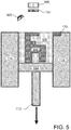
- FIG. 5 illustrates a side, cross-sectional view of a system, in accordance with aspects described herein.
- the heater 165 is arranged above the build platform 112, and may be a flash lamp.
- the infrared imaging device 160 is paired with a filter 161 that is configured for use with device 160.
- the filter 161 may have a spectral response between about 0.8 ⁇ m and about 1,000 ⁇ m, or any subranges therebetween.
- the filter 161 is a bandpass filter that targets all or a portion of the infrared spectrum, thereby increasing the signal to noise ratio for infrared imaging device 160.
- FIG. 6 is a flowchart of the method 600 for inspection of additive manufactured parts and monitoring operational performance of the additive manufacturing apparatus 100, in accordance with aspects described herein.
- the data extracted during thermographic scanning can be used for real time quality control, final quality control and feedback process control to correct the laser or machine properties.
- process i.e., real time
- machine control can be used to remove or cure flaws during the 3D build process.
- the infrared imaging device 160 may be calibrated.
- the calibration block 170 located so as to be within the field of view of infrared imaging device 160 (or vice-versa) and a scan is initiated.
- the response is compared to a known good response and responses of known artificial flaws in the calibration block in order to detect, evaluate, classify and size the defect or measure the layer thickness. If there is a discrepancy, the infrared imaging device (or output thereof) is modified to correct the error. This will yield a very reliable and repeatable scanning process.
- the height of the infrared imaging device can affect the response thereof, or the amount of background light, or the ambient temperature may be factors that affect the response of infrared imaging device 160.
- Calibration blocks 170 are provided to have an accurate and repeatable test for each layer, and to optimize the sensitivity of the scanner/sensors, and to use known defects with known sizes so that the system can use their data for sizing and defect classification.
- the calibration block is also capable of defining critical values such as reflectivity and emissivity values. These known defects can be designed and modified according to the sensitivity and kind of defects needed to be detected and classified. For example, if the critical defect size is a void of 2 mm diameter, a void with 2 mm diameter can be artificially made in the calibration block 170. The system calibrates before scanning to have its response accurately adjusted. Alternatively, 2 mm void and a 2 mm inclusion can be located in the calibration block 170 to use their response for classifying the kind of defect.
- heating step 620 the build platform area, on which at least one part 140 is built, is heated.
- the heating is accomplished with a heater 165, such as a high intensity (and short duration) flash lamp, a quartz lamp or any other suitable device.
- the heater 165 subjects the parts 140 to a rapid heat pulse that is at least partially absorbed and then reflected by the parts 140 and the surrounding powder 130.
- the heating can also be done by eddy current induction or ultrasound, as previously described.
- obtaining step 630 a thermographic scan of the build platform area and parts 140 is obtained in real-time during an additively manufactured build process.
- An infrared imaging device 160 is used to obtain the thermographic scan or image.
- the device 160 may be an infrared camera, a focal plane array infrared sensor, a vanadium oxide microbolometer array sensor, or any other suitable imaging device.
- the infrared imaging device may employ a filter 161 having a spectral response in the infrared spectrum (e.g., between about 0.8 ⁇ m and about 1,000 ⁇ m, or any subranges therebetween).
- thermographic scan (or image) is evaluated, typically by a processor.
- the scan is analyzed and evaluated for areas or regions that may indicate presence of a defect in the part 140.
- the scan data may be evaluated to ascertain characteristics (dimensions, textures, layer thickness, composition, etc.) of the structure(s) being printed and compare these to a 'golden standard', such as a computer-aided design (CAD) specification for the structure.
- CAD computer-aided design
- the CAD specification may be a specification that the additive manufacturing apparatus uses in building the structure. The comparison can assess whether the part is being built consistent with the CAD specification in order to identify possible distortions, deviations, defects or other flaws.
- the evaluation of the scans can additionally identify features in the data that suggest problems with the additive manufacturing apparatus, such as, lack of fusion, porosity or micro/macro cracks or other items that indicate a flaw.
- the data can be evaluated to not only detect errors in the part(s) being built as they are printed, and assign a part 'health' score to each part(s), but also monitor additive manufacturing apparatus health, indicating when the machine might require maintenance or adjustment and identifying what is needed for that maintenance/adjustment.
- the evaluation is performed in real-time during the build process, though in other examples, the evaluation is performed at a later time.
- the data is retained for final assessment, creating a statistical model and system training.
- the data in this step is retained in a memory for the final part/structure assessment, as well as for creating a statistical model, machine learning and system training.
- the gathered data of the same layer of multiple defect-free parts can be used as an input to a machine learning algorithm such as Artificial Neural Networks (ANNs) to train the algorithm to be used for defect detection and classification of parts for that specific layer.
- ANNs Artificial Neural Networks
- One aspect of the current method is that after detecting the flaw, the method classifies the flaw so that the corrective action or decision can be made accordingly.
- Data corresponding to each layer is aggregated into a group corresponding to each part, and in this way a three dimensional "picture" is formed of the multiple layers in each part.
- step 650 a determination is made as to whether an operational flaw with the additive manufacturing apparatus has occurred or a defect in the part has occurred, and if the flaw and/or defect is acceptable or correctible or if the layer thickness is acceptable.
- Different decision making algorithms such as binary hypothesis testing, or Bayesian hypothesis testing can be used and optimized using the statistical model in step 645. For example, if the defect is smaller than a predetermined amount (e.g., less than 0.5 mm), then the build process can continue. If the flaw is correctible, then step 660 is used to correct the flaw. If the defect was an unfused area, then the laser could be directed to re-target that flawed area. However, if the defect is neither acceptable nor correctible, then the part is discarded and the build process for that part ends with step 670.
- a predetermined amount e.g., less than 0.5 mm
- FIG. 7 illustrates a schematic representation of the control system and the additive manufacturing apparatus, in accordance with aspects described herein.
- Additive manufacturing apparatus 100 may include a control system including one or more controller(s) 710, including hardware and/or software for controlling functioning of some or all components of the additive manufacturing apparatus 100.
- Controller(s) 710 may control, for instance, operation of laser 102 (including laser power, laser speed, laser spot size, etc.), recoating blade position, speed or height, and dispensing and build platform operation (e.g., amount of height increase/decrease, etc.).
- controller(s) 710 include one or more control data processing systems for controlling the print process and behavior of the other hardware of the printing apparatus. Control algorithms such as Proportional-Integral-Derivative (PID), Linear Quadratic Regulator (LQR), Fuzzy Logic Controller (FLC) and other suitable control algorithm can be used to calculate the multiple output parameters with respect to input data.
- PID Proportional-Integral-Derivative
- LQR Linear Quadratic Regulator
- FLC Fuzzy Logic Controller
- the infrared imaging device 160 may capture data in real-time during the build process. The data may then be evaluated, in real time, in one example, using one or more algorithms executed as software on a data processing system.
- the data processing system may be included as part of the apparatus 100, in one example. In other examples, the data processing system is in wired or wireless communication with infrared imaging device 160 responsible for acquiring the scan data, where the infrared imaging device communicates the data through one or more wired or wireless communication paths to the data processing system.
- the separate data processing system may be a controller 710 data processing system described above, or may be a different data processing system dedicated to evaluation of the acquired scan data.
- the data processing system that obtains the scan data may evaluate the data, either separately or by one or more of various techniques for comparison with one or more three-dimensional CAD models, to determine whether the part(s) are being printed correctly.
- a designer of the parts to be printed may utilize software to build designs for all of the parts to be printed onto the build platform.
- Software for controlling the additive manufacturing apparatus may then (offline) 'slice' the 3D models of the part(s) to be printed into layers, with each layer to be printed as a 'pass' of the laser.
- layers of a build process may be thermographically scanned and the properties and characteristics of the printed materials may be compared to a CAD specification in order to assess the quality of the build and determine whether operational flaw(s) or defects have occurred.
- the scanning of one or more layers in real time during the additive manufacturing process, and the evaluation of the scan data, which may be in real-time during the build process or may be at a later time, provides online inspection of parts and process monitoring that facilitates assessment of the operational health of the additive manufacturing apparatus.
- FIG. 8 illustrates one example of a data processing system to incorporate and use one or more aspects described herein.
- Data processing system 800 is suitable for storing and/or executing program code, such as program code for performing the processes described above, and includes at least one processor 802 coupled directly or indirectly to memory 804 through, a bus 820.
- processor(s) 802 obtain from memory 804 one or more instructions for execution by the processors.
- Memory 804 may include local memory employed during actual execution of the program code, bulk storage, and cache memories which provide temporary storage of at least some program code in order to reduce the number of times code must be retrieved from bulk storage during program code execution.
- memory 804 includes a hard disk, a random access memory (RAM), a read-only memory (ROM), an erasable programmable read-only memory (EPROM or Flash memory), an optical fiber, a portable compact disc read-only memory (CD-ROM), an optical storage device, a magnetic storage device, or any suitable combination of the foregoing.
- Memory 804 includes an operating system 805 and one or more computer programs 806, such as one or more programs for obtaining scan data from an infrared imaging device 160, and one or more programs for evaluating the obtained scan data to determine whether operational flaws(s) have occurred with an additive manufacturing apparatus or defects have occurred in the parts, in accordance with aspects described herein.
- I/O devices 812, 814 may be coupled to the system either directly or through I/O controllers 810.
- Network adapters 808 may also be coupled to the system to enable the data processing system to become coupled to other data processing systems through intervening private or public networks. Modems, cable modem and ethernet cards are just a few of the currently available types of network adapters 808.
- network adapters 808 and/or input devices 812 facilitate obtaining scan data of a build process in which a three-dimensional structure is printed.
- Data processing system 800 may be coupled to storage 816 (e.g., a non-volatile storage area, such as magnetic disk drives, optical disk drives, a tape drive, cloud storage, etc.), having one or more databases.
- Storage 816 may include an internal storage device or an attached or network accessible storage. Computer programs in storage 816 may be loaded into memory 804 and executed by a processor 802 in a manner known in the art.
- data processing system 800 may be communicatively coupled to the infrared imaging device 160 via one or more communication paths, such as a network communication path, serial connection, or similar, for communicating data between data processing system 800 and the infrared imaging device. Communication may include acquisition by the data processing system of the data acquired by the infrared imaging device 160.
- the data processing system 800 may include fewer components than illustrated, additional components not illustrated herein, or some combination of the components illustrated and additional components.
- Data processing system 800 may include any computing device known in the art, such as a mainframe, server, personal computer, workstation, laptop, handheld computer, tablet, smartphone, telephony device, network appliance, virtualization device, storage controller, etc.
- processes described above may be performed by multiple data processing systems 800, working as part of a clustered computing environment.
- Data processing system 800, memory 804 and/or storage 816 may include data compression algorithms specifically designed for 3D printing due to the large amount of data needed to be stored for each part.
- aspects of the present invention may take the form of a computer program product embodied in one or more computer readable medium(s).
- the one or more computer readable medium(s) may have embodied thereon computer readable program code.
- Various computer readable medium(s) or combinations thereof may be utilized.
- the computer readable medium(s) may comprise a computer readable storage medium, examples of which include (but are not limited to) one or more electronic, magnetic, optical, or semiconductor systems, apparatuses, or devices, or any suitable combination of the foregoing.
- Example computer readable storage medium(s) include, for instance: an electrical connection having one or more wires, a portable computer diskette, a hard disk or mass-storage device, a random access memory (RAM), read-only memory (ROM), and/or erasable-programmable read-only memory such as EPROM or flash memory, an optical fiber, a portable compact disc read-only memory (CD-ROM), an optical storage device, a magnetic storage device (including a tape device), or any suitable combination of the above.
- a computer readable storage medium is defined to comprise a tangible medium that can contain or store program code for use by or in connection with an instruction execution system, apparatus, or device, such as a processor. The program code stored in/on the computer readable medium therefore produces an article of manufacture (such as a "computer program product") including program code.
- a computer program product 900 includes, for instance, one or more computer readable media 902 to store computer readable program code means or logic 904 thereon to provide and facilitate one or more aspects of the present invention.
- Program code contained or stored in/on a computer readable medium 902 can be obtained and executed by a data processing system (computer, computer system, etc. including a component thereof) and/or other devices to cause the data processing system, component thereof, and/or other device to behave/function in a particular manner.
- the program code can be transmitted using any appropriate medium, including (but not limited to) wireless, wireline, optical fiber, and/or radio-frequency.
- Program code for carrying out operations to perform, achieve, or facilitate aspects of the present invention may be written in one or more programming languages.
- the programming language(s) include object-oriented and/or procedural programming languages such as C, C++, C#, Java, etc.
- Program code may execute entirely on the user's computer, entirely remote from the user's computer, or a combination of partly on the user's computer and partly on a remote computer.
- a user's computer and a remote computer are in communication via a network such as a local area network (LAN) or a wide area network (WAN), and/or via an external computer (for example, through the Internet using an Internet Service Provider).
- LAN local area network
- WAN wide area network
- Internet Service Provider for example, AT&T, MCI, Sprint, EarthLink, etc.
- program code includes one or more program instructions obtained for execution by one or more processors.
- Computer program instructions may be provided to one or more processors of, e.g., one or more data processing system, to produce a machine, such that the program instructions, when executed by the one or more processors, perform, achieve, or facilitate aspects of the present invention, such as actions or functions described in flowcharts and/or block diagrams described herein.
- each block, or combinations of blocks, of the flowchart illustrations and/or block diagrams depicted and described herein can be implemented, in some embodiments, by computer program instructions.
- each block in a flowchart or block diagram may represent a module, segment, or portion of code, which comprises one or more executable instructions for implementing the specified behaviors and/or logical functions of the block.
- behaviors/functions specified or performed by a block may occur in a different order than depicted and/or described, or may occur simultaneous to, or partially/wholly concurrent with, one or more other blocks.
- Two blocks shown in succession may, in fact, be executed substantially concurrently, or the blocks may sometimes be executed in the reverse order.
- each block of the block diagrams and/or flowchart illustrations, and combinations of blocks in the block diagrams and/or flowchart illustrations can be implemented wholly by special-purpose hardware-based systems, or in combination with computer instructions, that perform the behaviors/functions specified by a block or entire block diagram or flowchart.
- the method and system of the present invention not only aims at evaluating and modifying the 3D manufacturing apparatus, but is also designed to evaluate each 3D printed part/structure in real time and after the build is completed. For example, the performance of a machine might be very satisfactory, but due to material or other issues some defects occur during the build.
- Non-destructive testing methods that have to be done to inspect each part in the past can now be eliminated using the inventive method and system, since the part/structure is inspected/assessed as it is constructed.
- Non-destructive testing of completed 3D parts may be undesirable because, it is very difficult to perform NDT on the parts due to complex geometry, and complex material properties, and computed tomography (CT) is very time consuming, costly and has other disadvantages.
- CT computed tomography
- a method or device that "comprises”, “has”, “includes” or “contains” one or more steps or elements possesses those one or more steps or elements, but is not limited to possessing only those one or more steps or elements.
- a step of a method or an element of a device that "comprises”, “has”, “includes” or “contains” one or more features possesses those one or more features, but is not limited to possessing only those one or more features.
- a device or structure that is configured in a certain way is configured in at least that way, but may also be configured in ways that are not listed.
- the terms “determine” or “determining” as used herein can include, e.g. in situations where a processor performs the determining, performing one or more calculations or mathematical operations to obtain a result.
Landscapes
- Engineering & Computer Science (AREA)
- Chemical & Material Sciences (AREA)
- Materials Engineering (AREA)
- Manufacturing & Machinery (AREA)
- Physics & Mathematics (AREA)
- Mechanical Engineering (AREA)
- Automation & Control Theory (AREA)
- Optics & Photonics (AREA)
- General Physics & Mathematics (AREA)
- Spectroscopy & Molecular Physics (AREA)
- Analytical Chemistry (AREA)
- Plasma & Fusion (AREA)
- General Health & Medical Sciences (AREA)
- Life Sciences & Earth Sciences (AREA)
- Biochemistry (AREA)
- Health & Medical Sciences (AREA)
- Immunology (AREA)
- Pathology (AREA)
- Radiation Pyrometers (AREA)
- Powder Metallurgy (AREA)
- Studio Devices (AREA)
- Photometry And Measurement Of Optical Pulse Characteristics (AREA)
Applications Claiming Priority (1)
| Application Number | Priority Date | Filing Date | Title |
|---|---|---|---|
| US15/296,354 US20180104742A1 (en) | 2016-10-18 | 2016-10-18 | Method and system for thermographic inspection of additive manufactured parts |
Publications (1)
| Publication Number | Publication Date |
|---|---|
| EP3312009A1 true EP3312009A1 (fr) | 2018-04-25 |
Family
ID=60143539
Family Applications (1)
| Application Number | Title | Priority Date | Filing Date |
|---|---|---|---|
| EP17196918.1A Withdrawn EP3312009A1 (fr) | 2016-10-18 | 2017-10-17 | Procédé et système d'inspection thermographique de pièces fabriquées de manière additive |
Country Status (3)
| Country | Link |
|---|---|
| US (1) | US20180104742A1 (fr) |
| EP (1) | EP3312009A1 (fr) |
| JP (1) | JP2018100954A (fr) |
Cited By (2)
| Publication number | Priority date | Publication date | Assignee | Title |
|---|---|---|---|---|
| EP3403745A1 (fr) * | 2017-05-15 | 2018-11-21 | MTU Aero Engines GmbH | Dispositif de fabrication en couche et procédé de fabrication en couche destinés à la fabrication additive d'au moins une zone de composant d'un composant |
| FR3125979A1 (fr) | 2021-08-09 | 2023-02-10 | Cogit Composites | Installation de fabrication additive par dépôt de fil fondu comportant une buse d'extrusion et un dispositif de mesure et de contrôle thermique du procédé. |
Families Citing this family (36)
| Publication number | Priority date | Publication date | Assignee | Title |
|---|---|---|---|---|
| DE102013217422A1 (de) | 2013-09-02 | 2015-03-05 | Carl Zeiss Industrielle Messtechnik Gmbh | Koordinatenmessgerät und Verfahren zur Vermessung und mindestens teilweisen Erzeugung eines Werkstücks |
| US10168217B2 (en) | 2016-09-28 | 2019-01-01 | Amazon Technologies, Inc. | Automated thermographic inspection for composite structures |
| US10175186B2 (en) * | 2016-09-28 | 2019-01-08 | Amazon Technologies, Inc. | Thermographic inspection process for composite vehicle and components |
| WO2018109734A2 (fr) * | 2016-12-18 | 2018-06-21 | Csir | Appareil et procédé de fabrication additive |
| US10473603B2 (en) | 2017-04-18 | 2019-11-12 | Saudi Arabian Oil Company | Apparatus, system and method for inspecting composite structures using quantitative infra-red thermography |
| US10234848B2 (en) * | 2017-05-24 | 2019-03-19 | Relativity Space, Inc. | Real-time adaptive control of additive manufacturing processes using machine learning |
| US10551297B2 (en) * | 2017-09-22 | 2020-02-04 | Saudi Arabian Oil Company | Thermography image processing with neural networks to identify corrosion under insulation (CUI) |
| DE102017130282A1 (de) * | 2017-12-18 | 2019-06-19 | MTU Aero Engines AG | Verfahren und Vorrichtung zum additiven Herstellen eines Bauteil sowie Bauteil |
| WO2019206903A1 (fr) | 2018-04-23 | 2019-10-31 | Carl Zeiss Industrial Metrology, Llc | Procédé et agencement pour produire une pièce à travailler à l'aide d'une commande en boucle fermée adaptative de techniques de fabrication additive |
| JP7030635B2 (ja) * | 2018-07-06 | 2022-03-07 | 株式会社東芝 | 付加製造方法及び付加製造システム |
| JP2020015944A (ja) * | 2018-07-25 | 2020-01-30 | 株式会社ジェイテクト | 付加製造用学習モデル生成装置、付加製造による造形物の製造条件決定装置および付加製造による造形物の状態推定装置 |
| JP7204236B2 (ja) * | 2018-08-31 | 2023-01-16 | 国立大学法人大阪大学 | 金属積層造形装置及び金属積層造形方法 |
| US11971699B2 (en) | 2018-10-29 | 2024-04-30 | Hewlett-Packard Development Company, L.P. | Thermal mapping |
| US11511491B2 (en) * | 2018-11-08 | 2022-11-29 | General Electric Company | Machine learning assisted development in additive manufacturing |
| CN111204042A (zh) * | 2018-11-21 | 2020-05-29 | 三纬国际立体列印科技股份有限公司 | 具红外线测温器校正结构的3d打印装置 |
| WO2020153949A1 (fr) | 2019-01-23 | 2020-07-30 | Hewlett-Packard Development Company, L.P. | Détection de glissement de pièce tridimensionnelle (3d) |
| US11407179B2 (en) | 2019-03-20 | 2022-08-09 | General Electric Company | Recoater automated monitoring systems and methods for additive manufacturing machines |
| DE102019110360A1 (de) * | 2019-04-18 | 2020-10-22 | Volume Graphics Gmbh | Computer-implementiertes Verfahren zur Bestimmung von Defekten eines mittels eines additiven Fertigungsprozesses hergestellten Objekts |
| WO2020228964A1 (fr) * | 2019-05-16 | 2020-11-19 | Vestel Elektronik Sanayi Ve Ticaret A.S. | Cuiseur à induction, procédé et produit programme d'ordinateur pour régler un entrefer pour une bobine d'induction |
| EP3999320A4 (fr) * | 2019-07-19 | 2023-05-10 | Hewlett-Packard Development Company, L.P. | Adaptation de simulations |
| US20220410489A1 (en) * | 2019-12-19 | 2022-12-29 | The Penn State Research Foundation | Determining build orientation to minimize thermal distortion |
| US11151728B2 (en) * | 2019-12-20 | 2021-10-19 | Ship And Ocean Industries R&D Center | Structure monitoring system and method |
| KR102236149B1 (ko) * | 2019-12-31 | 2021-04-06 | 한국과학기술원 | 3d 프린팅 시스템 및 이의 실시간 피드백 공정제어 방법 |
| KR102236148B1 (ko) * | 2019-12-31 | 2021-04-06 | 한국과학기술원 | 3d 프린팅 공정 중 형성되는 용융풀 크기를 제어할 수 있는 3d 프린팅 시스템 및 방법 |
| KR102194694B1 (ko) * | 2019-12-31 | 2020-12-24 | 한국과학기술원 | 3d 프린팅 공정의 열 화상 및 레이저 초음파 통합 검사 시스템 및 이를 구비한 3d 프린팅 시스템 |
| KR102194695B1 (ko) * | 2019-12-31 | 2020-12-24 | 한국과학기술원 | 3d 프린팅 공정 중 형성되는 적층부의 높이를 추정하는 방법 및 장치, 이를 구비한 3d 프린팅 시스템 |
| CN111203539B (zh) | 2020-04-22 | 2020-07-28 | 中国航发上海商用航空发动机制造有限责任公司 | 预制气孔缺陷、内置气孔缺陷的制备方法及预制件 |
| US11680909B2 (en) * | 2020-05-14 | 2023-06-20 | The Boeing Company | Automated inspection of foreign materials, cracks and other surface anomalies |
| WO2021257100A1 (fr) * | 2020-06-19 | 2021-12-23 | Hewlett-Packard Development Company, L.P. | Génération d'image thermique |
| US11565477B2 (en) | 2020-09-16 | 2023-01-31 | General Electric Company | Test article for additive manufacture and related methods |
| JP7165957B2 (ja) * | 2020-10-20 | 2022-11-07 | 石川県 | 造形状態推定システム、方法、コンピュータプログラム、及び学習モデルの学習方法 |
| US20220193784A1 (en) * | 2020-12-18 | 2022-06-23 | The Boeing Company | Additive manufacturing optical inspection system |
| DE102020134795A1 (de) * | 2020-12-23 | 2022-06-23 | Carl Zeiss Ag | Verfahren und Vorrichtung zur additiven Herstellung eines Werkstücks |
| US11599084B2 (en) * | 2021-06-18 | 2023-03-07 | Kyndryl, Inc. | Early notification system of degradation of 3D printed parts |
| CN113837225A (zh) * | 2021-08-25 | 2021-12-24 | 佛山科学技术学院 | 一种基于深度学习的缺陷检测3d打印装置及方法 |
| KR102592578B1 (ko) * | 2021-12-06 | 2023-10-23 | 한국재료연구원 | 복합 분말 적층 제조 시스템 및 복합 분말 적층 제조 방법 |
Citations (4)
| Publication number | Priority date | Publication date | Assignee | Title |
|---|---|---|---|---|
| US6930278B1 (en) * | 2004-08-13 | 2005-08-16 | 3D Systems, Inc. | Continuous calibration of a non-contact thermal sensor for laser sintering |
| EP2518480A1 (fr) * | 2011-04-27 | 2012-10-31 | General Electric Company | Système et procédé de contrôle thermographique |
| DE102014212246B3 (de) * | 2014-06-26 | 2015-08-06 | MTU Aero Engines AG | Verfahren und Vorrichtung zur Qualitätssicherung |
| US20150352794A1 (en) * | 2014-06-05 | 2015-12-10 | Commonwealth Scientific And Industrial Research Organisation | Distortion prediction and minimisation in additive manufacturing |
Family Cites Families (5)
| Publication number | Priority date | Publication date | Assignee | Title |
|---|---|---|---|---|
| US8653461B1 (en) * | 2007-03-23 | 2014-02-18 | Flir Systems, Inc. | Thermography camera tuned to detect absorption of infrared radiation in a selected spectral bandwidth |
| US7515986B2 (en) * | 2007-04-20 | 2009-04-07 | The Boeing Company | Methods and systems for controlling and adjusting heat distribution over a part bed |
| US10183329B2 (en) * | 2013-07-19 | 2019-01-22 | The Boeing Company | Quality control of additive manufactured parts |
| US9999924B2 (en) * | 2014-08-22 | 2018-06-19 | Sigma Labs, Inc. | Method and system for monitoring additive manufacturing processes |
| KR102463958B1 (ko) * | 2015-06-12 | 2022-11-04 | 머티어리얼리스 엔브이 | 열 이미징을 이용한 적층 제조시의 일관성을 보장하는 시스템 및 방법 |
-
2016
- 2016-10-18 US US15/296,354 patent/US20180104742A1/en not_active Abandoned
-
2017
- 2017-10-04 JP JP2017193927A patent/JP2018100954A/ja active Pending
- 2017-10-17 EP EP17196918.1A patent/EP3312009A1/fr not_active Withdrawn
Patent Citations (4)
| Publication number | Priority date | Publication date | Assignee | Title |
|---|---|---|---|---|
| US6930278B1 (en) * | 2004-08-13 | 2005-08-16 | 3D Systems, Inc. | Continuous calibration of a non-contact thermal sensor for laser sintering |
| EP2518480A1 (fr) * | 2011-04-27 | 2012-10-31 | General Electric Company | Système et procédé de contrôle thermographique |
| US20150352794A1 (en) * | 2014-06-05 | 2015-12-10 | Commonwealth Scientific And Industrial Research Organisation | Distortion prediction and minimisation in additive manufacturing |
| DE102014212246B3 (de) * | 2014-06-26 | 2015-08-06 | MTU Aero Engines AG | Verfahren und Vorrichtung zur Qualitätssicherung |
Cited By (2)
| Publication number | Priority date | Publication date | Assignee | Title |
|---|---|---|---|---|
| EP3403745A1 (fr) * | 2017-05-15 | 2018-11-21 | MTU Aero Engines GmbH | Dispositif de fabrication en couche et procédé de fabrication en couche destinés à la fabrication additive d'au moins une zone de composant d'un composant |
| FR3125979A1 (fr) | 2021-08-09 | 2023-02-10 | Cogit Composites | Installation de fabrication additive par dépôt de fil fondu comportant une buse d'extrusion et un dispositif de mesure et de contrôle thermique du procédé. |
Also Published As
| Publication number | Publication date |
|---|---|
| JP2018100954A (ja) | 2018-06-28 |
| US20180104742A1 (en) | 2018-04-19 |
Similar Documents
| Publication | Publication Date | Title |
|---|---|---|
| EP3312009A1 (fr) | Procédé et système d'inspection thermographique de pièces fabriquées de manière additive | |
| EP3323617B1 (fr) | Procédé et système d'inspection par rétrodiffusion de rayons x de pièces fabriquées de manière additive | |
| EP3282252A1 (fr) | Procédé et système d'inspection de pièces fabriquées de manière additive | |
| EP3308945B1 (fr) | Procédé et système d'inspection fondée sur la topographie et de commande de processus pour des pièces fabriquées par fabrication additive | |
| US20210146447A1 (en) | Additive manufacturing method and apparatus | |
| US11607875B2 (en) | Method and system for monitoring additive manufacturing processes | |
| CN109203479B (zh) | 用于先进增材制造的系统和方法 | |
| US20160098825A1 (en) | Feature extraction method and system for additive manufacturing | |
| CN107848209B (zh) | 使用热成像确保增材制造中的一致性的系统和方法 | |
| Clijsters et al. | In situ quality control of the selective laser melting process using a high-speed, real-time melt pool monitoring system | |
| US11493906B2 (en) | Online monitoring of additive manufacturing using acoustic emission methods | |
| Zenzinger et al. | Process monitoring of additive manufacturing by using optical tomography | |
| US20150177158A1 (en) | Operational performance assessment of additive manufacturing | |
| Sreeraj et al. | A review on non-destructive evaluation and characterization of additively manufactured components | |
| Yi et al. | Optical sensor-based process monitoring in additive manufacturing | |
| Guerra et al. | Off-axis monitoring of the melt pool spatial information in Laser Metal Deposition process | |
| Bowoto et al. | Enhancing dimensional accuracy in 3D printing: a novel software algorithm for real-time quality assessment | |
| Williams et al. | Localised porosity detection in laser powder bed fusion using in-situ monitoring | |
| Lu et al. | Additive Manufacturing Data and Metadata Acquisition—General Practice | |
| Lanigan et al. | In Situ Process Control and Monitoring in Additive Manufacturing—An Overview | |
| CN117349720A (zh) | 基于金属增材制造的原位质量评价方法及系统 |
Legal Events
| Date | Code | Title | Description |
|---|---|---|---|
| PUAI | Public reference made under article 153(3) epc to a published international application that has entered the european phase |
Free format text: ORIGINAL CODE: 0009012 |
|
| STAA | Information on the status of an ep patent application or granted ep patent |
Free format text: STATUS: THE APPLICATION HAS BEEN PUBLISHED |
|
| AK | Designated contracting states |
Kind code of ref document: A1 Designated state(s): AL AT BE BG CH CY CZ DE DK EE ES FI FR GB GR HR HU IE IS IT LI LT LU LV MC MK MT NL NO PL PT RO RS SE SI SK SM TR |
|
| AX | Request for extension of the european patent |
Extension state: BA ME |
|
| STAA | Information on the status of an ep patent application or granted ep patent |
Free format text: STATUS: REQUEST FOR EXAMINATION WAS MADE |
|
| 17P | Request for examination filed |
Effective date: 20181025 |
|
| RBV | Designated contracting states (corrected) |
Designated state(s): AL AT BE BG CH CY CZ DE DK EE ES FI FR GB GR HR HU IE IS IT LI LT LU LV MC MK MT NL NO PL PT RO RS SE SI SK SM TR |
|
| STAA | Information on the status of an ep patent application or granted ep patent |
Free format text: STATUS: THE APPLICATION IS DEEMED TO BE WITHDRAWN |
|
| 18D | Application deemed to be withdrawn |
Effective date: 20200603 |