EP3311990A1 - Composite member - Google Patents
Composite member Download PDFInfo
- Publication number
- EP3311990A1 EP3311990A1 EP15895597.1A EP15895597A EP3311990A1 EP 3311990 A1 EP3311990 A1 EP 3311990A1 EP 15895597 A EP15895597 A EP 15895597A EP 3311990 A1 EP3311990 A1 EP 3311990A1
- Authority
- EP
- European Patent Office
- Prior art keywords
- fiber
- surface side
- reinforced resin
- bonded
- front surface
- Prior art date
- Legal status (The legal status is an assumption and is not a legal conclusion. Google has not performed a legal analysis and makes no representation as to the accuracy of the status listed.)
- Granted
Links
Images


Classifications
-
- B—PERFORMING OPERATIONS; TRANSPORTING
- B29—WORKING OF PLASTICS; WORKING OF SUBSTANCES IN A PLASTIC STATE IN GENERAL
- B29C—SHAPING OR JOINING OF PLASTICS; SHAPING OF MATERIAL IN A PLASTIC STATE, NOT OTHERWISE PROVIDED FOR; AFTER-TREATMENT OF THE SHAPED PRODUCTS, e.g. REPAIRING
- B29C39/00—Shaping by casting, i.e. introducing the moulding material into a mould or between confining surfaces without significant moulding pressure; Apparatus therefor
- B29C39/02—Shaping by casting, i.e. introducing the moulding material into a mould or between confining surfaces without significant moulding pressure; Apparatus therefor for making articles of definite length, i.e. discrete articles
- B29C39/10—Shaping by casting, i.e. introducing the moulding material into a mould or between confining surfaces without significant moulding pressure; Apparatus therefor for making articles of definite length, i.e. discrete articles incorporating preformed parts or layers, e.g. casting around inserts or for coating articles
-
- B—PERFORMING OPERATIONS; TRANSPORTING
- B29—WORKING OF PLASTICS; WORKING OF SUBSTANCES IN A PLASTIC STATE IN GENERAL
- B29C—SHAPING OR JOINING OF PLASTICS; SHAPING OF MATERIAL IN A PLASTIC STATE, NOT OTHERWISE PROVIDED FOR; AFTER-TREATMENT OF THE SHAPED PRODUCTS, e.g. REPAIRING
- B29C45/00—Injection moulding, i.e. forcing the required volume of moulding material through a nozzle into a closed mould; Apparatus therefor
- B29C45/14—Injection moulding, i.e. forcing the required volume of moulding material through a nozzle into a closed mould; Apparatus therefor incorporating preformed parts or layers, e.g. injection moulding around inserts or for coating articles
-
- B—PERFORMING OPERATIONS; TRANSPORTING
- B29—WORKING OF PLASTICS; WORKING OF SUBSTANCES IN A PLASTIC STATE IN GENERAL
- B29C—SHAPING OR JOINING OF PLASTICS; SHAPING OF MATERIAL IN A PLASTIC STATE, NOT OTHERWISE PROVIDED FOR; AFTER-TREATMENT OF THE SHAPED PRODUCTS, e.g. REPAIRING
- B29C70/00—Shaping composites, i.e. plastics material comprising reinforcements, fillers or preformed parts, e.g. inserts
- B29C70/04—Shaping composites, i.e. plastics material comprising reinforcements, fillers or preformed parts, e.g. inserts comprising reinforcements only, e.g. self-reinforcing plastics
- B29C70/06—Fibrous reinforcements only
-
- B—PERFORMING OPERATIONS; TRANSPORTING
- B29—WORKING OF PLASTICS; WORKING OF SUBSTANCES IN A PLASTIC STATE IN GENERAL
- B29C—SHAPING OR JOINING OF PLASTICS; SHAPING OF MATERIAL IN A PLASTIC STATE, NOT OTHERWISE PROVIDED FOR; AFTER-TREATMENT OF THE SHAPED PRODUCTS, e.g. REPAIRING
- B29C70/00—Shaping composites, i.e. plastics material comprising reinforcements, fillers or preformed parts, e.g. inserts
- B29C70/04—Shaping composites, i.e. plastics material comprising reinforcements, fillers or preformed parts, e.g. inserts comprising reinforcements only, e.g. self-reinforcing plastics
- B29C70/06—Fibrous reinforcements only
- B29C70/10—Fibrous reinforcements only characterised by the structure of fibrous reinforcements, e.g. hollow fibres
- B29C70/16—Fibrous reinforcements only characterised by the structure of fibrous reinforcements, e.g. hollow fibres using fibres of substantial or continuous length
- B29C70/18—Fibrous reinforcements only characterised by the structure of fibrous reinforcements, e.g. hollow fibres using fibres of substantial or continuous length in the form of a mat, e.g. sheet moulding compound [SMC]
-
- B—PERFORMING OPERATIONS; TRANSPORTING
- B29—WORKING OF PLASTICS; WORKING OF SUBSTANCES IN A PLASTIC STATE IN GENERAL
- B29C—SHAPING OR JOINING OF PLASTICS; SHAPING OF MATERIAL IN A PLASTIC STATE, NOT OTHERWISE PROVIDED FOR; AFTER-TREATMENT OF THE SHAPED PRODUCTS, e.g. REPAIRING
- B29C70/00—Shaping composites, i.e. plastics material comprising reinforcements, fillers or preformed parts, e.g. inserts
- B29C70/68—Shaping composites, i.e. plastics material comprising reinforcements, fillers or preformed parts, e.g. inserts by incorporating or moulding on preformed parts, e.g. inserts or layers, e.g. foam blocks
-
- B—PERFORMING OPERATIONS; TRANSPORTING
- B29—WORKING OF PLASTICS; WORKING OF SUBSTANCES IN A PLASTIC STATE IN GENERAL
- B29C—SHAPING OR JOINING OF PLASTICS; SHAPING OF MATERIAL IN A PLASTIC STATE, NOT OTHERWISE PROVIDED FOR; AFTER-TREATMENT OF THE SHAPED PRODUCTS, e.g. REPAIRING
- B29C70/00—Shaping composites, i.e. plastics material comprising reinforcements, fillers or preformed parts, e.g. inserts
- B29C70/68—Shaping composites, i.e. plastics material comprising reinforcements, fillers or preformed parts, e.g. inserts by incorporating or moulding on preformed parts, e.g. inserts or layers, e.g. foam blocks
- B29C70/681—Component parts, details or accessories; Auxiliary operations
-
- B—PERFORMING OPERATIONS; TRANSPORTING
- B29—WORKING OF PLASTICS; WORKING OF SUBSTANCES IN A PLASTIC STATE IN GENERAL
- B29C—SHAPING OR JOINING OF PLASTICS; SHAPING OF MATERIAL IN A PLASTIC STATE, NOT OTHERWISE PROVIDED FOR; AFTER-TREATMENT OF THE SHAPED PRODUCTS, e.g. REPAIRING
- B29C70/00—Shaping composites, i.e. plastics material comprising reinforcements, fillers or preformed parts, e.g. inserts
- B29C70/68—Shaping composites, i.e. plastics material comprising reinforcements, fillers or preformed parts, e.g. inserts by incorporating or moulding on preformed parts, e.g. inserts or layers, e.g. foam blocks
- B29C70/685—Shaping composites, i.e. plastics material comprising reinforcements, fillers or preformed parts, e.g. inserts by incorporating or moulding on preformed parts, e.g. inserts or layers, e.g. foam blocks by laminating inserts between two plastic films or plates
-
- B—PERFORMING OPERATIONS; TRANSPORTING
- B29—WORKING OF PLASTICS; WORKING OF SUBSTANCES IN A PLASTIC STATE IN GENERAL
- B29C—SHAPING OR JOINING OF PLASTICS; SHAPING OF MATERIAL IN A PLASTIC STATE, NOT OTHERWISE PROVIDED FOR; AFTER-TREATMENT OF THE SHAPED PRODUCTS, e.g. REPAIRING
- B29C70/00—Shaping composites, i.e. plastics material comprising reinforcements, fillers or preformed parts, e.g. inserts
- B29C70/68—Shaping composites, i.e. plastics material comprising reinforcements, fillers or preformed parts, e.g. inserts by incorporating or moulding on preformed parts, e.g. inserts or layers, e.g. foam blocks
- B29C70/74—Moulding material on a relatively small portion of the preformed part, e.g. outsert moulding
- B29C70/745—Filling cavities in the preformed part
-
- B—PERFORMING OPERATIONS; TRANSPORTING
- B32—LAYERED PRODUCTS
- B32B—LAYERED PRODUCTS, i.e. PRODUCTS BUILT-UP OF STRATA OF FLAT OR NON-FLAT, e.g. CELLULAR OR HONEYCOMB, FORM
- B32B5/00—Layered products characterised by the non- homogeneity or physical structure, i.e. comprising a fibrous, filamentary, particulate or foam layer; Layered products characterised by having a layer differing constitutionally or physically in different parts
- B32B5/02—Layered products characterised by the non- homogeneity or physical structure, i.e. comprising a fibrous, filamentary, particulate or foam layer; Layered products characterised by having a layer differing constitutionally or physically in different parts characterised by structural features of a fibrous or filamentary layer
- B32B5/024—Woven fabric
-
- B—PERFORMING OPERATIONS; TRANSPORTING
- B32—LAYERED PRODUCTS
- B32B—LAYERED PRODUCTS, i.e. PRODUCTS BUILT-UP OF STRATA OF FLAT OR NON-FLAT, e.g. CELLULAR OR HONEYCOMB, FORM
- B32B5/00—Layered products characterised by the non- homogeneity or physical structure, i.e. comprising a fibrous, filamentary, particulate or foam layer; Layered products characterised by having a layer differing constitutionally or physically in different parts
- B32B5/22—Layered products characterised by the non- homogeneity or physical structure, i.e. comprising a fibrous, filamentary, particulate or foam layer; Layered products characterised by having a layer differing constitutionally or physically in different parts characterised by the presence of two or more layers which are next to each other and are fibrous, filamentary, formed of particles or foamed
- B32B5/24—Layered products characterised by the non- homogeneity or physical structure, i.e. comprising a fibrous, filamentary, particulate or foam layer; Layered products characterised by having a layer differing constitutionally or physically in different parts characterised by the presence of two or more layers which are next to each other and are fibrous, filamentary, formed of particles or foamed one layer being a fibrous or filamentary layer
- B32B5/28—Layered products characterised by the non- homogeneity or physical structure, i.e. comprising a fibrous, filamentary, particulate or foam layer; Layered products characterised by having a layer differing constitutionally or physically in different parts characterised by the presence of two or more layers which are next to each other and are fibrous, filamentary, formed of particles or foamed one layer being a fibrous or filamentary layer impregnated with or embedded in a plastic substance
-
- B—PERFORMING OPERATIONS; TRANSPORTING
- B29—WORKING OF PLASTICS; WORKING OF SUBSTANCES IN A PLASTIC STATE IN GENERAL
- B29K—INDEXING SCHEME ASSOCIATED WITH SUBCLASSES B29B, B29C OR B29D, RELATING TO MOULDING MATERIALS OR TO MATERIALS FOR MOULDS, REINFORCEMENTS, FILLERS OR PREFORMED PARTS, e.g. INSERTS
- B29K2105/00—Condition, form or state of moulded material or of the material to be shaped
- B29K2105/06—Condition, form or state of moulded material or of the material to be shaped containing reinforcements, fillers or inserts
- B29K2105/08—Condition, form or state of moulded material or of the material to be shaped containing reinforcements, fillers or inserts of continuous length, e.g. cords, rovings, mats, fabrics, strands or yarns
- B29K2105/0809—Fabrics
-
- B—PERFORMING OPERATIONS; TRANSPORTING
- B32—LAYERED PRODUCTS
- B32B—LAYERED PRODUCTS, i.e. PRODUCTS BUILT-UP OF STRATA OF FLAT OR NON-FLAT, e.g. CELLULAR OR HONEYCOMB, FORM
- B32B2260/00—Layered product comprising an impregnated, embedded, or bonded layer wherein the layer comprises an impregnation, embedding, or binder material
- B32B2260/02—Composition of the impregnated, bonded or embedded layer
- B32B2260/021—Fibrous or filamentary layer
- B32B2260/023—Two or more layers
-
- B—PERFORMING OPERATIONS; TRANSPORTING
- B32—LAYERED PRODUCTS
- B32B—LAYERED PRODUCTS, i.e. PRODUCTS BUILT-UP OF STRATA OF FLAT OR NON-FLAT, e.g. CELLULAR OR HONEYCOMB, FORM
- B32B2262/00—Composition or structural features of fibres which form a fibrous or filamentary layer or are present as additives
- B32B2262/10—Inorganic fibres
- B32B2262/106—Carbon fibres, e.g. graphite fibres
Definitions
- Patent Document 1 Japanese Laid-Open Patent Application No. 2013-23184
- an object of the present invention is to provide a composite member that can further improve the bonding strength between a bonding member and a bonded member to.
- the composite member according to the present invention is obtained by bonding a bonding member made of fiber-reinforced resin to a bonded member comprising a through-hole.
- a front surface side fiber-reinforced resin, a rear surface side fiber-reinforced resin, and a bonded member are integrally bonded with a resin, in a state in which the fibers of at least one fiber-reinforced resin of the rear surface side fiber-reinforced resin and the front surface side fiber-reinforced resin, which are bonding members, are inserted in the through-hole of the bonded member.
- a bonding member and a bonded member are integrally bonded with a resin, in a state in which the fibers of at least one fiber-reinforced resin of the front surface side fiber-reinforced resin and the rear surface side fiber-reinforced resin are inserted in a through-hole of the bonded member. Therefore, the fibers inserted in the through-hole of the bonded member are bonded to the inner perimeter surface of the through-hole. Therefore, when fibers are inserted in a through-hole of a bonded member, as in the present invention, the bonding strength between the bonding member and the bonded member is further enhanced, compared to a case in which fibers are not inserted in a through-hole of the bonded member.
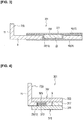
- the composite member 1 according to the first embodiment comprises a bonding member 3 having two or more fiber-reinforced resins containing a multiplicity of continuous fibers, and a bonded member 5 that is bonded to the bonding member 3 via a resin, as illustrated in Figure 1 .
- the bonded member 5 is a bracket 7 made of metal, such as a steel plate.
- This bracket 7 is formed in an L-shape in side view from a flat plate-shaped main body portion 9, and an extending portion 11 that is bent along an edge of the plate main body portion 9 and extends upwardly.
- Various metals may be employed, and the applicable thickness is, for example, 1.0-5.0 mm.
- a through-hole 13 is formed in the plate main body portion 9.
- Various shapes may be employed for this through-hole 13, and a hole diameter of 5.0-50 mm, for example, may be applied.
- the bonding member 3 comprises a front surface side fiber-reinforced resin sheet 15 (front surface side fiber-reinforced resin 17) formed in a plate shape and disposed on the front surface side of the bracket 7 (bonded member 5), and a rear surface side fiber-reinforced resin sheet 19 (rear surface side fiber-reinforced resin 21) formed in a plate shape and disposed on the rear surface side of the bracket 7 (bonded member 5).
- the portion of the front surface side fiber-reinforced resin sheet 15 that corresponds to the through-hole 13 of the bracket 7 is inserted in the through-hole 13 of the bracket 7 and brought close to the rear surface side fiber-reinforced resin sheet 19. That is, the portion of the front surface side fiber-reinforced resin sheet 15 that corresponds to the through-hole 13 of the bracket 7 is formed in a recessed portion 23, and the rear surface side fiber-reinforced resin sheet 19 is formed in a planar shape across the entire surface.
- the side surface of the recessed portion 23 of the front surface side fiber-reinforced resin sheet 15 is disposed along the inner perimeter surface 25 of the through-hole of the bracket 7.
- a composite member 1 is molded by integrally bonding the front surface side fiber-reinforced resin sheet 15, the rear surface side fiber-reinforced resin sheet 19, and the bracket 7 to each other with resin in a state in which the fibers of the front surface side fiber-reinforced resin sheet 15 are inserted into the through-hole 13 of the bracket 7.
- the bonding strength between the bonding member 3 and the bracket 7 is further enhanced, compared to a case in which fibers are not inserted in a through-hole 13 of the bracket 7.
- a holding substrate 317 that is formed to have the same thickness as the bracket 7 is sandwiched between the fiber substrate 303 of the first fiber layer 307 and the fiber substrate 311 of the second fiber layer 315.
- This holding substrate 317 is interposed for the purpose of preventing the first fiber layer 307 and the second fiber layer 315 from becoming dented when the first fiber layer 307 and the second fiber layer 315 are pressed against each other in the thickness direction.
- the front surface side fiber-reinforced resin of the bonding member is a first fiber layer 307 in which a nap 305 is provided on the rear surface of a fiber substrate 303
- the rear surface side fiber-reinforced resin of the bonding member is a second fiber layer 315 in which a nap 313 is provided on the front surface of a fiber substrate 311, as illustrated in Figure 5 .
- the first fiber layer 307 described above is disposed on the front surface side of the bracket 7, and the nap 305 of the first fiber layer 307 is inserted in the through-hole 13 of the bracket 7.
- the applicable thickness of the fiber substrate 303 of the first fiber layer 307 and the fiber substrate 311 of the second fiber layer 315 is, for example, 0.4-5.0 mm. Additionally, the applicable thickness of the nonwoven fabric layer 403 is, for example, 0.2-10.0 mm.
- a nonwoven fabric layer 403 is disposed between the third fiber layer 415 of the bonding member and the bracket 7, and the bonding member is bonded to the bracket 7 by integrally bonding the first fiber layer 307, the third fiber layer 415, the nonwoven fabric layer 403, and the bracket 7 to each other with the resin, in a state in which the fibers of the nonwoven fabric layer 403 are intertwined with the nap 305 of the first fiber layer 307 inserted in the through-hole 13 of the bracket 7.
- the applicable thickness of the fiber substrate 303 of the first fiber layer 307 and the fiber substrate 311 of the second fiber layer 315 is, for example, 0.4-5.0 mm. Additionally, the applicable thickness of the nonwoven fabric layer 403 is, for example, 0.4-5.0 mm.
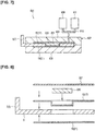
- the molding device 601 used in the resin injection method is configured from a metal mold 607 comprising a lower die 603 disposed on the lower side and an upper mold 605 disposed on the upper side, a first tank 609 and a second tank 611 that store the molten resin to be poured into a cavity inside the metal mold 607, and a pipe 613 that connects the first tank 609 and the second tank 611 with the cavity inside the metal mold 611, as illustrated in Figure 7 .
- the rear surface side fiber-reinforced resin sheet 19, the front surface side fiber-reinforced resin sheet 15, the spacer 230, the coating fiber-reinforced resin sheet 231, and the bracket 7 are arranged in the lower die 603. Thereafter, the upper die 605 is closed, and molten resin is poured from the first tank 609 and the second tank 611 into the cavity inside the metal mold 607 via the pipe 613.
Landscapes
- Engineering & Computer Science (AREA)
- Mechanical Engineering (AREA)
- Chemical & Material Sciences (AREA)
- Composite Materials (AREA)
- Textile Engineering (AREA)
- Manufacturing & Machinery (AREA)
- Laminated Bodies (AREA)
- Moulding By Coating Moulds (AREA)
- Casting Or Compression Moulding Of Plastics Or The Like (AREA)
Abstract
Description
- The present invention relates to a composite member, and more specifically to a composite member that uses a fiber-reinforced resin.
- Conventionally, a composite member obtained by bonding a bonding member containing a fiber-reinforced resin to a member to be bonded is known (for example, refer to Patent Document 1).
- A hood outer panel (composite member) disclosed in this
Patent Document 1 is obtained by bonding an outer panel body (composite member) made of carbon fiber-reinforced resin and a metal bracket (bonded member) with a matrix resin, in a state in which the outer panel body is inserted into the metal bracket. - Specifically, first, a front surface layer made of a carbon fiber woven fabric is disposed on the front surface side of a metal bracket having a through-hole, and a nonwoven fabric and a rear surface layer made of carbon fiber woven fabric are disposed on the rear surface side of the metal bracket. Next, the metal bracket, the front surface layer, the nonwoven fabric, and the rear surface layer are placed in a metal mold, molten resin (matrix resin) is poured into the metal mold, and the metal mold is opened after the molten resin has cured, at which point the metal bracket is bonded to the outer panel body via the matrix resin. The hood outer panel described above is thereby completed.
- In the above-described
Patent Document 1, the fibers of the front surface layer and the fibers of the nonwoven fabric are not inserted in the through-hole of the metal bracket, while the molten resin flows into the through-hole of the metal bracket and is hardened. - Patent Document 1: Japanese Laid-Open Patent Application No.
2013-23184 - However, in recent years, further improvements in the bonding strength have been desired when bonding a bonded member, such as a metal bracket, and a bonding member, such as a front surface layer, a rear surface layer, and a nonwoven fabric.
- Therefore, an object of the present invention is to provide a composite member that can further improve the bonding strength between a bonding member and a bonded member to.
- The composite member according to the present invention is obtained by bonding a bonding member made of fiber-reinforced resin to a bonded member comprising a through-hole. Specifically, a front surface side fiber-reinforced resin, a rear surface side fiber-reinforced resin, and a bonded member are integrally bonded with a resin, in a state in which the fibers of at least one fiber-reinforced resin of the rear surface side fiber-reinforced resin and the front surface side fiber-reinforced resin, which are bonding members, are inserted in the through-hole of the bonded member.
- According to the composite member of the present invention, a bonding member and a bonded member are integrally bonded with a resin, in a state in which the fibers of at least one fiber-reinforced resin of the front surface side fiber-reinforced resin and the rear surface side fiber-reinforced resin are inserted in a through-hole of the bonded member. Therefore, the fibers inserted in the through-hole of the bonded member are bonded to the inner perimeter surface of the through-hole. Therefore, when fibers are inserted in a through-hole of a bonded member, as in the present invention, the bonding strength between the bonding member and the bonded member is further enhanced, compared to a case in which fibers are not inserted in a through-hole of the bonded member.
-
- [
Figure 1 ] is a cross-sectional view of a composite member according to a first embodiment of the present invention. - [
Figure 2 ] is a cross-sectional view of a composite member according to a second embodiment of the present invention. - [
Figure 3 ] is a cross-sectional view of a composite member according to a third embodiment of the present invention. - [
Figure 4 ] is a cross-sectional view of a composite member according to a fourth embodiment of the present invention. - [
Figure 5 ] is a cross-sectional view of a composite member according to a fifth embodiment of the present invention. - [
Figure 6 ] is a cross-sectional view of a composite member according to a sixth embodiment of the present invention. - [
Figure 7 ] is a cross-sectional view explaining the resin injection method for molding the composite member of the present invention. - [
Figure 8 ] is a cross-sectional view explaining the prepreg method for molding the composite member of the present invention. - [
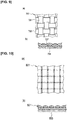
Figure 9 ] is a view illustrating a fabric as the first and second fiber layers; (a) is a plan view of the fabric, and (b) is a cross-sectional view of (a). - [
Figure 10 ] is a view illustrating a multiaxial substrate as the first and second fiber layers; (a) is a plan view of the multiaxial substrate, and (b) is a cross-sectional view of (a). - [
Figure 11 ] is a view illustrating a pile as the first and second fiber layers. - [
Figure 12 ] is a view illustrating a cut pile as the first and second fiber layers. - Embodiments of the present invention will be described below based on the drawings.
- First, the composite member according to a first embodiment of the present invention will be described.
- The
composite member 1 according to the first embodiment comprises abonding member 3 having two or more fiber-reinforced resins containing a multiplicity of continuous fibers, and a bondedmember 5 that is bonded to thebonding member 3 via a resin, as illustrated inFigure 1 . - Specifically, the
bonded member 5 is abracket 7 made of metal, such as a steel plate. Thisbracket 7 is formed in an L-shape in side view from a flat plate-shapedmain body portion 9, and an extendingportion 11 that is bent along an edge of the platemain body portion 9 and extends upwardly. Various metals may be employed, and the applicable thickness is, for example, 1.0-5.0 mm. In addition, a through-hole 13 is formed in the platemain body portion 9. Various shapes may be employed for this through-hole 13, and a hole diameter of 5.0-50 mm, for example, may be applied. - The
bonding member 3 comprises a front surface side fiber-reinforced resin sheet 15 (front surface side fiber-reinforced resin 17) formed in a plate shape and disposed on the front surface side of the bracket 7 (bonded member 5), and a rear surface side fiber-reinforced resin sheet 19 (rear surface side fiber-reinforced resin 21) formed in a plate shape and disposed on the rear surface side of the bracket 7 (bonded member 5). - The front surface side fiber-reinforced
resin sheet 15 contains multiple carbon fibers (continuous fibers), and the applicable sheet thickness is, for example, 0.4-3.0 mm. The rear surface side fiber-reinforcedresin sheet 19 contains multiple carbon fibers (continuous fibers), and the applicable sheet thickness is, for example, 0.4-5.0 mm. - Here, the portion of the front surface side fiber-reinforced
resin sheet 15 that corresponds to the through-hole 13 of thebracket 7 is inserted in the through-hole 13 of thebracket 7 and brought close to the rear surface side fiber-reinforcedresin sheet 19. That is, the portion of the front surface side fiber-reinforcedresin sheet 15 that corresponds to the through-hole 13 of thebracket 7 is formed in arecessed portion 23, and the rear surface side fiber-reinforcedresin sheet 19 is formed in a planar shape across the entire surface. The side surface of therecessed portion 23 of the front surface side fiber-reinforcedresin sheet 15 is disposed along theinner perimeter surface 25 of the through-hole of thebracket 7. In this manner, in the first embodiment, acomposite member 1 is molded by integrally bonding the front surface side fiber-reinforcedresin sheet 15, the rear surface side fiber-reinforcedresin sheet 19, and thebracket 7 to each other with resin in a state in which the fibers of the front surface side fiber-reinforcedresin sheet 15 are inserted into the through-hole 13 of thebracket 7. - The action and effects of the first embodiment will be described below.
- (1) The
composite member 1 according to the first embodiment comprises a bondingmember 3 made of a fiber-reinforced resin containing multiple continuous fibers, and a bracket 7 (bonded member 5) that is bonded to thebonding member 3 via a resin. Thebracket 7 has a through-hole 13 that extends through in the thickness direction, and thebonding member 3 comprises a front surface side fiber-reinforced resin sheet 15 (front surface side fiber-reinforced resin 17) that is disposed on the front surface side of thebracket 7, and a rear surface side fiber-reinforced resin sheet 19 (rear surface side fiber-reinforced resin 21) that is disposed on the rear surface side of thebracket 7. Thebonding member 3 is bonded to thebracket 7 by integrally bonding the front surface side fiber-reinforcedresin sheet 15, the rear surface side fiber-reinforcedresin sheet 19, and thebracket 7 to each other by the resin, in a state in which the fibers of at least one fiber-reinforced resin of the front surface side fiber-reinforcedresin sheet 15 and the rear surface side fiber-reinforcedresin sheet 19 are inserted in the through-hole 13 of thebracket 7. - In this manner, in a state in which the fibers of at least one fiber-reinforced resin of the front surface side fiber-reinforced
resin sheet 15 and the rear surface side fiber-reinforcedresin sheet 19 are inserted in the through-hole 13 of thebracket 7, thebonding member 3 and thebracket 7 are integrally bonded to each other by the resin. Therefore, the fibers that are inserted in the through-hole 13 of thebracket 7 are bonded to theinner perimeter surface 25 of the through-hole 13 by means of the resin. Therefore, when fibers are inserted in a through-hole 13 of thebracket 7, as in the present invention, the bonding strength between thebonding member 3 and thebracket 7 is further enhanced, compared to a case in which fibers are not inserted in a through-hole 13 of thebracket 7. - Next, the second embodiment will be described, but the configurations that are the same as the above-described first embodiment are given the same reference symbols, and the descriptions thereof are omitted.
- In the first embodiment, only the front surface side fiber-reinforced resin sheet is inserted in the through-hole of the bracket to form a recessed portion. However, in the
composite member 101 according to the second embodiment, portions of both the front surface side fiber-reinforced resin sheet 115 (front surface side fiber-reinforced resin 117) and the rear surface side fiber-reinforced resin sheet 119 (rear surface side fiber-reinforced resin 121) that correspond to the through-hole 13 of the bracket 7 (bonded member 5) are inserted in the through-hole 13 of thebracket 7, to bring both the front surface side fiber-reinforcedresin sheet 115 and the rear surface side fiber-reinforcedresin sheet 119 in contact with each other, as illustrated inFigure 2 . As a result, arecessed portion 123a is formed on the front surface side fiber-reinforcedresin sheet 115, and a recessedportion 123b is also formed on the rear surface side fiber-reinforcedresin sheet 119. That is, the height position at which therecessed portions resin sheet 115 and the rear surface side fiber-reinforcedresin sheet 119 that correspond to the through-hole 13 of thebracket 7 come into contact with each other is the center portion of the bracket 7 (bonded member 5) in the thickness direction. - The action and effects of the second embodiment will be described below.
- (1) A
bonding member 103 and a bondedmember 5 are integrally bonded with a resin, in a state in which the fibers of at least one fiber-reinforced resin of the front surface side fiber-reinforced resin sheet 115 (front surface side fiber-reinforced resin 117) and the rear surface side fiber-reinforced resin sheet 119 (rear surface side fiber-reinforced resin 121) are inserted in a through-hole 13 of the bracket 7 (bonded member 5). Therefore, the fibers inserted in the through-hole 13 of the bondedmember 5 are bonded to theinner perimeter surface 25 of the through-hole 13. Therefore, when the fibers are inserted in a through-hole 13 of a bondedmember 5, as in the present invention, the bonding strength between the bondingmember 103 and the bondedmember 5 is further enhanced, compared to a case in which fibers are not inserted in a through-hole 13 of the bondedmember 5. - Next, the third embodiment will be described, but the configurations that are the same as the above-described first and second embodiments are given the same reference symbols, and the descriptions thereof are omitted.
- In the
composite member 201 according to the third embodiment, aspacer 230 and a coating fiber-reinforcedresin sheet 231 are added in the recessedportion 23 of thecomposite member 1 according to the first embodiment, as illustrated inFigure 3 . - Specifically, the portion of the front surface side fiber-reinforced
resin sheet 15 that corresponds to the through-hole 13 of thebracket 7 is inserted in the through-hole 13 of thebracket 7 and brought close to the rear surface side fiber-reinforcedresin sheet 19, to thereby form a recessedportion 23 on the front surface side fiber-reinforcedresin sheet 15. Then, a plate-like spacer 230 of predetermined thickness is housed in the recessedportion 23. For example, a nonwoven fabric layer (low density foam) can be used as thisspacer 230, and the thickness of thespacer 230 is preferably the same as the depth of the recessed portion 23 (for example, 1.0-5.0 mm). The applicable fiber length of the discontinuous fibers constituting the nonwoven fabric layer of thespacer 230 is, for example, 15-60 mm. In addition to a nonwoven fabric layer, one in which multiple pores are formed may be used as the spacer. Furthermore, the coating fiber-reinforcedresin sheet 231 contains carbon fibers (continuous fibers), and the applicable sheet thickness is, for example, 0.4-5.0 mm. Acomposite member 201 according to the second embodiment is molded by integrally bonding the front surface side fiber-reinforcedresin sheet 15, the rear surface side fiber-reinforcedresin sheet 19, thespacer 230, the coating fiber-reinforcedresin sheet 231, and thebracket 7 to each other with resin in a state in which the front surface side fiber-reinforcedresin sheet 15 and thespacer 230 are covered with the planar coating fiber-reinforcedresin sheet 231. - The action and effects of the third embodiment will be described below.
- (1) A recessed
portion 23 is formed by one of the front surface side fiber-reinforcedresin sheet 15 and the rear surface side fiber-reinforcedresin sheet 19, and aspacer 230 is disposed in the recessedportion 23. Here, if aspacer 230 is not disposed in the recessedportion 23, there is the risk that the portion corresponding to the recessedportion 23 will become dented if the coating fiber-reinforcedresin sheet 231 is pressed. Therefore, by disposing aspacer 230 in the recessedportion 23, when the coating fiber-reinforcedresin sheet 231 is pressed, the coating fiber-reinforcedresin sheet 231 comes in contact with the surface of thespacer 230 and generates an appropriate reaction force; it is thereby possible to suppress a depression deformation of the coating fiber-reinforcedresin sheet 231. - Next, the fourth embodiment will be described, but the configurations that are the same as the above-described first to third embodiments are given the same reference symbols, and the descriptions thereof are omitted.
- In the
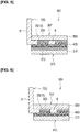
composite member 301 according to the fourth embodiment, the front surface side fiber-reinforced resin of the bonding member is afirst fiber layer 307 in which anap 305 is provided on the rear surface of afiber substrate 303, and the rear surface side fiber-reinforced resin of the bonding member is asecond fiber layer 315 in which anap 313 is provided on the front surface of afiber substrate 311, as illustrated inFigure 4 . Thefirst fiber layer 307 described above is disposed on the front surface side of thebracket 7, and thenap 305 of thefirst fiber layer 307 is inserted in the through-hole 13 of thebracket 7. In addition, thesecond fiber layer 315 of the bonding member is disposed on the rear surface side of thebracket 7, and thenap 313 of thesecond fiber layer 315 is inserted in the through-hole 13 of thebracket 7. As a result, thefirst fiber layer 307, thesecond fiber layer 315, and thebracket 7 are integrally bonded to each other by the resin, in a state in which thenap 305 of thefirst fiber layer 307 and thenap 313 of thesecond fiber layer 315 are intertwined with each other inside the through-hole 13 of thebracket 7. The applicable thickness of thefiber substrate 303 of thefirst fiber layer 307 and thefiber substrate 311 of thesecond fiber layer 315 is, for example, 0.4-5.0 mm. Furthermore, a holdingsubstrate 317 that is formed to have the same thickness as thebracket 7 is sandwiched between thefiber substrate 303 of thefirst fiber layer 307 and thefiber substrate 311 of thesecond fiber layer 315. This holdingsubstrate 317 is interposed for the purpose of preventing thefirst fiber layer 307 and thesecond fiber layer 315 from becoming dented when thefirst fiber layer 307 and thesecond fiber layer 315 are pressed against each other in the thickness direction. - The action and effects of the fourth embodiment will be described below.
- (1) Since the
nap 305 of thefirst fiber layer 307 and thenap 313 of thesecond fiber layer 315 are integrally bonded to each other with the resin in a state of being entangled with each other inside the through-hole 13 of thebracket 7, the bonding strength between the bonding member and the bonded member is further enhanced. - Next, the fourth embodiment will be described, but the configurations that are the same as the above-described first to third embodiments are given the same reference symbols, and the descriptions thereof are omitted.
- In the
composite member 401 according to the fifth embodiment, the front surface side fiber-reinforced resin of the bonding member is afirst fiber layer 307 in which anap 305 is provided on the rear surface of afiber substrate 303, and the rear surface side fiber-reinforced resin of the bonding member is asecond fiber layer 315 in which anap 313 is provided on the front surface of afiber substrate 311, as illustrated inFigure 5 . Thefirst fiber layer 307 described above is disposed on the front surface side of thebracket 7, and thenap 305 of thefirst fiber layer 307 is inserted in the through-hole 13 of thebracket 7. Thesecond fiber layer 315 of the bonding member is disposed on the rear surface side of thebracket 7, anonwoven fabric layer 403 is disposed between thesecond fiber layer 315 of the bonding member and thebracket 7, and the fibers of thenonwoven fabric layer 403 are intertwined with both thenap 305 of thefirst fiber layer 307 and thenap 313 of thesecond fiber layer 315, which are inserted in the through-hole 13 of thebracket 7. Thecomposite member 401 according to the fifth embodiment is molded by integrally bonding thefirst fiber layer 307, thesecond fiber layer 315, thenonwoven fabric layer 403, and thebracket 7 to each other by the resin in this state. The applicable thickness of thefiber substrate 303 of thefirst fiber layer 307 and thefiber substrate 311 of thesecond fiber layer 315 is, for example, 0.4-5.0 mm. Additionally, the applicable thickness of thenonwoven fabric layer 403 is, for example, 0.2-10.0 mm. - The action and effects of the fifth embodiment will be described below.
- (1) The fibers of the
nonwoven fabric layer 403 are intertwined with thenap 305 of thefirst fiber layer 307, and the fibers of thenonwoven fabric layer 403 are intertwined with thenap 313 of thesecond fiber layer 315. In this manner, thefirst fiber layer 307 is connected to thesecond fiber layer 315 via thenonwoven fabric layer 403. Therefore, since the bonding member holds the bonded member by sandwiching same from the front side and the rear side, the bonding strength between the bonding member and the bonded member is further enhanced. - Furthermore, the bonding strength between the bonding member and the bonded member is further enhanced by disposing the
nap 305 of thefirst fiber layer 307 and thenap 313 of thesecond fiber layer 315 in portions other than the through-hole 13 of thebracket 7, and causing same to intertwine with the fibers of thenonwoven fabric layer 403. - Next, the sixth embodiment will be described, but the configurations that are the same as the above-described first to fifth embodiments are given the same reference symbols, and the descriptions thereof are omitted.
- In the
composite member 501 according to the sixth embodiment, the front surface side fiber-reinforced resin of the bonding member is afirst fiber layer 307 in which anap 305 is provided on the rear surface of afiber substrate 303, and the rear surface side fiber-reinforced resin of the bonding member is athird fiber layer 415 made of afiber substrate 311, as illustrated inFIG. 6 - The
first fiber layer 307 described above is disposed on the front surface side of thebracket 7, and thenap 305 of thefirst fiber layer 307 is inserted in the through-hole 13 of thebracket 7. Thethird fiber layer 415 of the bonding member is disposed on the rear surface side of thebracket 7. In addition, anonwoven fabric layer 403 is disposed between thethird fiber layer 415 of the bonding member and thebracket 7, and the bonding member is bonded to thebracket 7 by integrally bonding thefirst fiber layer 307, thethird fiber layer 415, thenonwoven fabric layer 403, and thebracket 7 to each other with the resin, in a state in which the fibers of thenonwoven fabric layer 403 are intertwined with thenap 305 of thefirst fiber layer 307 inserted in the through-hole 13 of thebracket 7. The applicable thickness of thefiber substrate 303 of thefirst fiber layer 307 and thefiber substrate 311 of thesecond fiber layer 315 is, for example, 0.4-5.0 mm. Additionally, the applicable thickness of thenonwoven fabric layer 403 is, for example, 0.4-5.0 mm. - The action and effects of the sixth embodiment will be described below.
- (1) Since the bonding member holds the bonded member by sandwiching same from the front side and the rear side, the bonding strength between the bonding member and the bonded member is further enhanced.
- Next, the seventh embodiment will be described, but the configurations that are the same as the above-described first to sixth embodiments are given the same reference symbols, and the descriptions thereof are omitted.
- In the seventh embodiment, the resin injection method for producing the
composite member 201 according to the above-described third embodiment will be described. - The
molding device 601 used in the resin injection method is configured from ametal mold 607 comprising alower die 603 disposed on the lower side and anupper mold 605 disposed on the upper side, afirst tank 609 and asecond tank 611 that store the molten resin to be poured into a cavity inside themetal mold 607, and apipe 613 that connects thefirst tank 609 and thesecond tank 611 with the cavity inside themetal mold 611, as illustrated inFigure 7 . - First, the rear surface side fiber-reinforced
resin sheet 19, the front surface side fiber-reinforcedresin sheet 15, thespacer 230, the coating fiber-reinforcedresin sheet 231, and thebracket 7 are arranged in thelower die 603. Thereafter, theupper die 605 is closed, and molten resin is poured from thefirst tank 609 and thesecond tank 611 into the cavity inside themetal mold 607 via thepipe 613. Then, when the molten resin penetrates the rear surface side fiber-reinforcedresin sheet 19, the front surface side fiber-reinforcedresin sheet 15, thespacer 230, and the coating fiber-reinforcedresin sheet 231, and the molten resin cools and solidifies, thebracket 7 is bonded to thebracket 7 by the resin, and acomposite member 201 is formed. Then, themetal mold 607 is opened and thecomposite member 201 is removed. - Next, the eighth embodiment will be described, but the configurations that are the same as the above-described first to seventh embodiments are given the same reference symbols, and the descriptions thereof are omitted.
- In the eighth embodiment, the prepreg method for producing the
composite member 201 according to the above-described third embodiment will be described. - A prepreg is prepared by impregnating the rear surface side fiber-reinforced
resin sheet 19, the front surface side fiber-reinforcedresin sheet 15, thespacer 230, and the coating fiber-reinforcedresin sheet 231 according to the above-described third embodiment with molten resin and drying same, as illustrated inFigure 8 . Next, the prepreg and thebracket 7 are placed in a metal mold, which is not shown, and a high-temperature, high-pressure state is maintained. Then, the prepreg and thebracket 7 are bonded, and a composite member is formed. - Next, applicable first fiber layers in the above-described fourth to sixth embodiments will be described using
Figures 9-12 . -
Figure 9 is awoven fabric 705 in whichwarp threads 701 andweft threads 703 are woven orthogonally, and anap 709 extends from the rear surface of thefiber substrate 707.Figure 10 is amultiaxial substrate 801, also called a non-crimp fabric (N.C.F), and anap 803 is provided on the rear surface.Figure 11 is apile 901, and is obtained by connecting apile yarn 907 to afirst base fabric 903 and asecond base fabric 905.Figure 12 is acut pipe 1001, in which the distal end of thepile 901 ofFigure 11 is cut, and anap 1003 is provided on the rear surface thereof. - The present invention is not limited to the above-described embodiments, and various modifications and changes are possible. For example, in
Figure 1 , the front surface side fiber-reinforcedresin sheet 15 and the rear surface side fiber-reinforcedresin sheet 19 were placed in contact inside the through-hole 13 of thebracket 7; however, a gap may be provided between the front surface side fiber-reinforcedresin sheet 15 and the rear surface side fiber-reinforcedresin sheet 19, and the two may be disposed in proximity to each other. - Similarly, in
Figure 2 , the front surface side fiber-reinforcedresin sheet 115 and the rear surface side fiber-reinforcedresin sheet 119 were placed in contact inside the through-hole 13 of thebracket 7; however, a gap may be provided between the front surface side fiber-reinforcedresin sheet 115 and the rear surface side fiber-reinforcedresin sheet 119, and the two may be disposed in proximity to each other. -
- 1, 101, 201, 301, 401, 501 Composite member
- 3 Bonding member
- 5 Bonded Member
- 7 Bracket (Bonded member)
- 13 Through-hole
- 15 Front surface side fiber-reinforced resin sheet (front surface side fiber-reinforced resin)
- 19 Rear surface side fiber-reinforced resin sheet (rear surface side fiber-reinforced resin)
- 23 Recessed portion
- 115 Front surface side fiber-reinforced resin sheet (front surface side fiber-reinforced resin)
- 119 Rear surface side fiber-reinforced resin sheet (rear surface side fiber-reinforced resin)
- 230 Spacer
- 307 First fiber layer
- 305, 313 Nap
- 311 Fiber substrate
- 315 Second fiber layer
- 403 Nonwoven fabric layer
- 415 Third fiber layer
Claims (6)
- A composite member comprising:a bonding member made of a fiber-reinforced resin containing multiple continuous fibers; anda bonded member bonded to the bonding member via a resin, wherein
the bonded member has a through-hole that passes through a thickness direction,
the bonding member comprises a front surface side fiber-reinforced resin disposed on a front surface side of the bonded member, and a rear surface side fiber-reinforced resin disposed on a rear surface side of the bonded member, andthe front surface side fiber-reinforced resin, the rear surface side fiber-reinforced resin and the bonded member are integrally bonded with a resin in a state in which the fibers of at least one of the front surface side fiber-reinforced resin and the rear surface side fiber-reinforced resin of the fiber-reinforced resin are inserted in the through-hole of the bonded member to thereby bond the bonding member to the bonded member. - The composite member as recited in claim 1, wherein
the front surface side fiber-reinforced resin of the bonding member is a front surface side fiber-reinforced resin sheet formed in a plate shape,
the rear surface side fiber-reinforced resin of the bonding member is a rear surface side fiber-reinforced resin sheet formed in a plate shape, and
the front surface side fiber-reinforced resin sheet, the rear surface side fiber-reinforced resin sheet and the bonded member are integrally bonded with a resin in a state in which a portion of at least one of the front surface side fiber-reinforced resin sheet and the rear surface side fiber-reinforced resin sheet that corresponds to the through-hole of the bonded member is inserted in the through-hole of the bonded member to be brought close to the other sheet via the through-hole to thereby bond the bonding member to the bonded member. - The composite member as recited in claim 2, wherein
the portion of at least one of the front surface side fiber-reinforced resin sheet and the rear surface side fiber-reinforced resin sheet that corresponds to the through-hole of the bonded member is inserted in the through-hole of the bonded member to form a recessed portion that is recessed toward the other sheet side, and a spacer having a predetermined thickness is disposed in the recessed portion, and
in a state in which the one sheet and the spacer are covered with a coating fiber-reinforced resin sheet, the front surface side fiber-reinforced resin sheet, the rear surface side fiber-reinforced resin sheet, the spacer, the coating fiber-reinforced resin sheet and the bonded member are integrally bonded to each other with the resin to thereby bond the bonding member to the bonded member. - The composite member as recited in claim 1, wherein
the front surface side fiber-reinforced resin of the bonding member is a first fiber layer in which a nap is provided on a rear surface of a fiber substrate,
the rear surface side fiber-reinforced resin of the bonding member is a second fiber layer in which a nap is provided on a front surface of a fiber substrate,
the first fiber layer is disposed on a front surface side of the bonded member and the nap of the first fiber layer is inserted in the through-hole of the bonded member,
the second fiber layer of the bonding member is disposed on a rear surface side of the bonded member and the nap of the second fiber layer is inserted in the through-hole of the bonded member, and
the first fiber layer, the second fiber layer and the bonded member are integrally bonded to each other with the resin in a state in which the nap of the first fiber layer and the nap of the second fiber layer are intertwined with each other inside the through-hole of the bonded member to thereby bond the bonding member to the bonded member. - The composite member as recited in claim 1, wherein
the front surface side fiber-reinforced resin of the bonding member is a first fiber layer in which a nap is provided on a rear surface of a fiber substrate,
the rear surface side fiber-reinforced resin of the bonding member is a second fiber layer in which a nap is provided on a front surface of a fiber substrate,
the first fiber layer is disposed on a front surface side of the bonded member and the nap of the first fiber layer is inserted in the through-hole of the bonded member,
the second fiber layer of the bonding member is disposed on a rear surface side of the bonded member, and
a nonwoven fabric layer is disposed between the second fiber layer of the bonding member and the bonded member, and the first fiber layer, the second fiber layer, the nonwoven fabric layer and the bonded member are bonded to each other with the resin in a state in which the fiber of the nonwoven fabric layer is intertwined with both the nap of the first fiber layer and the nap of the second fiber layer inserted in the through-hole of the bonded member to thereby bond the bonding member to the bonded member. - The composite member as recited in claim 1, wherein
the front surface side fiber-reinforced resin of the bonding member is a first fiber layer in which a nap is provided on a rear surface of a fiber substrate,
the rear surface side fiber-reinforced resin of the bonding member is a third fiber layer made of a fiber substrate,
the first fiber layer is disposed on a front surface side of the bonded member and the nap of the first fiber layer is inserted in the through-hole of the bonded member,
the third fiber layer of the bonding member is disposed on the rear surface side of the bonded member, and
a nonwoven fabric layer is disposed between the third fiber layer of the bonding member and the bonded member, and the first fiber layer, the third fiber layer, the nonwoven fabric layer, and the bonded member are bonded to each other with the resin in a state in which the fibers of the nonwoven fabric layer are intertwined with the nap of the first fiber layer inserted in the through-hole of the bonded member to thereby bond the bonding member to the bonded member.
Applications Claiming Priority (1)
| Application Number | Priority Date | Filing Date | Title |
|---|---|---|---|
| PCT/JP2015/067467 WO2016203576A1 (en) | 2015-06-17 | 2015-06-17 | Composite member |
Publications (3)
| Publication Number | Publication Date |
|---|---|
| EP3311990A1 true EP3311990A1 (en) | 2018-04-25 |
| EP3311990A4 EP3311990A4 (en) | 2018-08-15 |
| EP3311990B1 EP3311990B1 (en) | 2020-09-02 |
Family
ID=57545215
Family Applications (1)
| Application Number | Title | Priority Date | Filing Date |
|---|---|---|---|
| EP15895597.1A Active EP3311990B1 (en) | 2015-06-17 | 2015-06-17 | Composite member |
Country Status (5)
| Country | Link |
|---|---|
| US (1) | US10899046B2 (en) |
| EP (1) | EP3311990B1 (en) |
| JP (1) | JP6455594B2 (en) |
| CN (1) | CN107708977B (en) |
| WO (1) | WO2016203576A1 (en) |
Cited By (1)
| Publication number | Priority date | Publication date | Assignee | Title |
|---|---|---|---|---|
| EP3991954A3 (en) * | 2020-10-28 | 2022-07-27 | Sedus Stoll AG | Method for producing a single-piece composite fibre structure comprising at least one fibre composite mat and fibre composite structure |
Families Citing this family (5)
| Publication number | Priority date | Publication date | Assignee | Title |
|---|---|---|---|---|
| JP6572822B2 (en) * | 2016-05-12 | 2019-09-11 | トヨタ自動車株式会社 | Method for producing fiber reinforced thermoplastic resin structure |
| WO2018193611A1 (en) * | 2017-04-21 | 2018-10-25 | 日産自動車株式会社 | Connection structure for components formed from fiber-reinforced resin and method for producing component formed from fiber-reinforced resin |
| JP7026466B2 (en) * | 2017-09-12 | 2022-02-28 | 株式会社Subaru | Metal-fiber reinforced resin joint member |
| JP7537333B2 (en) * | 2021-03-25 | 2024-08-21 | トヨタ紡織株式会社 | Composite materials, car seats, car parts |
| KR102466802B1 (en) * | 2021-06-22 | 2022-11-16 | 아진산업(주) | Forming Method Of Composite Material And Product Using The Same |
Family Cites Families (15)
| Publication number | Priority date | Publication date | Assignee | Title |
|---|---|---|---|---|
| US3895084A (en) * | 1972-03-28 | 1975-07-15 | Ducommun Inc | Fiber reinforced composite product |
| JPH04286628A (en) * | 1991-03-15 | 1992-10-12 | Sekisui Chem Co Ltd | Molding method for composite body of fiber reinforced synthetic resin |
| JPH054281A (en) * | 1991-06-28 | 1993-01-14 | Mitsubishi Heavy Ind Ltd | Composite fastener |
| JPH0596680A (en) * | 1991-10-08 | 1993-04-20 | Honda Motor Co Ltd | Lining member and manufacturing method thereof |
| JP3849567B2 (en) * | 2002-04-15 | 2006-11-22 | 日産自動車株式会社 | Bonding method and bonding structure between fiber reinforced resin and metal plate |
| JP4965324B2 (en) * | 2007-04-24 | 2012-07-04 | ポリマテック株式会社 | Decorative sheet, decorative molded body, decorative key sheet, and method for producing decorative sheet |
| CN101462382A (en) * | 2009-01-16 | 2009-06-24 | 武汉理工大学 | Sandwich structure composite material with elastic core material and preparation method thereof |
| JP2013023184A (en) | 2011-07-26 | 2013-02-04 | Toyota Industries Corp | Outer panel for transportation apparatus and method of manufacturing the same |
| JP5681617B2 (en) * | 2011-12-12 | 2015-03-11 | 本田技研工業株式会社 | Manufacturing method of fiber reinforced resin member with nut |
| CN105073389B (en) * | 2013-03-13 | 2018-04-03 | 爱信高丘株式会社 | Composite structure of fiber-reinforced plastic plate and metal plate and manufacturing method thereof |
| US9040138B2 (en) * | 2013-04-29 | 2015-05-26 | General Electric Company | Composite article including composite to metal interlock and method of fabrication |
| JP6070481B2 (en) * | 2013-08-28 | 2017-02-01 | トヨタ自動車株式会社 | Junction structure |
| CN103640267B (en) * | 2013-11-21 | 2016-03-02 | 苏州市莱赛电车技术有限公司 | A kind of Three-dimensional fiber composite material |
| JP2016016592A (en) * | 2014-07-09 | 2016-02-01 | 群馬県 | Dissimilar materials joining method |
| JP6064974B2 (en) * | 2014-10-24 | 2017-01-25 | トヨタ自動車株式会社 | Member connection method |
-
2015
- 2015-06-17 WO PCT/JP2015/067467 patent/WO2016203576A1/en not_active Ceased
- 2015-06-17 EP EP15895597.1A patent/EP3311990B1/en active Active
- 2015-06-17 CN CN201580080974.8A patent/CN107708977B/en active Active
- 2015-06-17 US US15/575,889 patent/US10899046B2/en active Active
- 2015-06-17 JP JP2017524206A patent/JP6455594B2/en active Active
Cited By (1)
| Publication number | Priority date | Publication date | Assignee | Title |
|---|---|---|---|---|
| EP3991954A3 (en) * | 2020-10-28 | 2022-07-27 | Sedus Stoll AG | Method for producing a single-piece composite fibre structure comprising at least one fibre composite mat and fibre composite structure |
Also Published As
| Publication number | Publication date |
|---|---|
| CN107708977A (en) | 2018-02-16 |
| EP3311990A4 (en) | 2018-08-15 |
| EP3311990B1 (en) | 2020-09-02 |
| US10899046B2 (en) | 2021-01-26 |
| WO2016203576A1 (en) | 2016-12-22 |
| JP6455594B2 (en) | 2019-01-23 |
| JPWO2016203576A1 (en) | 2018-03-08 |
| CN107708977B (en) | 2021-01-15 |
| US20180126605A1 (en) | 2018-05-10 |
Similar Documents
| Publication | Publication Date | Title |
|---|---|---|
| EP3311990B1 (en) | Composite member | |
| JP6213673B2 (en) | COMPOSITE MATERIAL MOLDED BODY AND MANUFACTURING METHOD THEREOF | |
| US10889076B2 (en) | Method for producing fiber-reinforced resin shaped product | |
| JP6372195B2 (en) | Preform manufacturing method and fiber reinforced plastic manufacturing method | |
| JP5737870B2 (en) | Non-woven materials for fiber reinforced composites | |
| KR20160132294A (en) | Injection modlding method and injection molded part using fiber reinforced composite material | |
| JP2013502332A (en) | Injection molding method for manufacturing components | |
| JP5725741B2 (en) | Fiber reinforced composite | |
| JP2015178241A (en) | Method of producing fiber-reinforced resin material | |
| JP5682843B2 (en) | Long fiber reinforced resin molded body and method for producing the same | |
| CN109866435A (en) | Fiber-reinforced resin body and its manufacturing method | |
| EP2889131A1 (en) | A Laminated Composite Structure and Related Method | |
| CN108712951B (en) | Method for producing composite material | |
| JP2014100911A (en) | Preform and production method of the same | |
| JP6059841B1 (en) | Molding method of resin structure integrated with two-dimensional steel fabric | |
| JP2015199321A (en) | Manufacturing method of molded products | |
| CN104105584B (en) | Preparation method of fiber-reinforced resin | |
| JP5598931B2 (en) | Fiber reinforced resin substrate, method for producing resin molded body, and resin processing machine for implementing the method | |
| CN103347666B (en) | The manufacture method of preform | |
| DE102010045220A1 (en) | Injection molding device for impregnation of e.g. fabric, with thermoplastic matrix polymer for manufacturing motor vehicle components, has upper and lower parts with lower and upper sides whose surface is lined with spacer material layer | |
| JP2011202303A (en) | Fiber structure and method for producing the same, and preform | |
| JP2008137179A (en) | Manufacturing method of fiber reinforced plastic | |
| JP2018047577A (en) | Method for molding composite material | |
| JP2018001718A (en) | Preform, method for producing preform, and fiber-reinforced plastic using the preform | |
| JP2010274612A (en) | Manufacturing method of FRP molded product by RTM molding method and mold therefor |
Legal Events
| Date | Code | Title | Description |
|---|---|---|---|
| STAA | Information on the status of an ep patent application or granted ep patent |
Free format text: STATUS: THE INTERNATIONAL PUBLICATION HAS BEEN MADE |
|
| PUAI | Public reference made under article 153(3) epc to a published international application that has entered the european phase |
Free format text: ORIGINAL CODE: 0009012 |
|
| STAA | Information on the status of an ep patent application or granted ep patent |
Free format text: STATUS: REQUEST FOR EXAMINATION WAS MADE |
|
| 17P | Request for examination filed |
Effective date: 20180108 |
|
| AK | Designated contracting states |
Kind code of ref document: A1 Designated state(s): AL AT BE BG CH CY CZ DE DK EE ES FI FR GB GR HR HU IE IS IT LI LT LU LV MC MK MT NL NO PL PT RO RS SE SI SK SM TR |
|
| AX | Request for extension of the european patent |
Extension state: BA ME |
|
| A4 | Supplementary search report drawn up and despatched |
Effective date: 20180718 |
|
| RIC1 | Information provided on ipc code assigned before grant |
Ipc: B32B 5/28 20060101ALI20180712BHEP Ipc: B29C 70/68 20060101ALI20180712BHEP Ipc: B29C 45/14 20060101ALI20180712BHEP Ipc: B29C 39/10 20060101ALI20180712BHEP Ipc: B29C 70/74 20060101ALI20180712BHEP Ipc: B29C 70/06 20060101AFI20180712BHEP |
|
| DAV | Request for validation of the european patent (deleted) | ||
| DAX | Request for extension of the european patent (deleted) | ||
| STAA | Information on the status of an ep patent application or granted ep patent |
Free format text: STATUS: EXAMINATION IS IN PROGRESS |
|
| 17Q | First examination report despatched |
Effective date: 20190823 |
|
| GRAP | Despatch of communication of intention to grant a patent |
Free format text: ORIGINAL CODE: EPIDOSNIGR1 |
|
| STAA | Information on the status of an ep patent application or granted ep patent |
Free format text: STATUS: GRANT OF PATENT IS INTENDED |
|
| INTG | Intention to grant announced |
Effective date: 20200430 |
|
| GRAS | Grant fee paid |
Free format text: ORIGINAL CODE: EPIDOSNIGR3 |
|
| GRAA | (expected) grant |
Free format text: ORIGINAL CODE: 0009210 |
|
| STAA | Information on the status of an ep patent application or granted ep patent |
Free format text: STATUS: THE PATENT HAS BEEN GRANTED |
|
| AK | Designated contracting states |
Kind code of ref document: B1 Designated state(s): AL AT BE BG CH CY CZ DE DK EE ES FI FR GB GR HR HU IE IS IT LI LT LU LV MC MK MT NL NO PL PT RO RS SE SI SK SM TR |
|
| REG | Reference to a national code |
Ref country code: GB Ref legal event code: FG4D |
|
| REG | Reference to a national code |
Ref country code: AT Ref legal event code: REF Ref document number: 1308347 Country of ref document: AT Kind code of ref document: T Effective date: 20200915 Ref country code: CH Ref legal event code: EP |
|
| REG | Reference to a national code |
Ref country code: DE Ref legal event code: R096 Ref document number: 602015058633 Country of ref document: DE |
|
| REG | Reference to a national code |
Ref country code: IE Ref legal event code: FG4D |
|
| REG | Reference to a national code |
Ref country code: LT Ref legal event code: MG4D |
|
| PG25 | Lapsed in a contracting state [announced via postgrant information from national office to epo] |
Ref country code: GR Free format text: LAPSE BECAUSE OF FAILURE TO SUBMIT A TRANSLATION OF THE DESCRIPTION OR TO PAY THE FEE WITHIN THE PRESCRIBED TIME-LIMIT Effective date: 20201203 Ref country code: NO Free format text: LAPSE BECAUSE OF FAILURE TO SUBMIT A TRANSLATION OF THE DESCRIPTION OR TO PAY THE FEE WITHIN THE PRESCRIBED TIME-LIMIT Effective date: 20201202 Ref country code: LT Free format text: LAPSE BECAUSE OF FAILURE TO SUBMIT A TRANSLATION OF THE DESCRIPTION OR TO PAY THE FEE WITHIN THE PRESCRIBED TIME-LIMIT Effective date: 20200902 Ref country code: BG Free format text: LAPSE BECAUSE OF FAILURE TO SUBMIT A TRANSLATION OF THE DESCRIPTION OR TO PAY THE FEE WITHIN THE PRESCRIBED TIME-LIMIT Effective date: 20201202 Ref country code: FI Free format text: LAPSE BECAUSE OF FAILURE TO SUBMIT A TRANSLATION OF THE DESCRIPTION OR TO PAY THE FEE WITHIN THE PRESCRIBED TIME-LIMIT Effective date: 20200902 Ref country code: HR Free format text: LAPSE BECAUSE OF FAILURE TO SUBMIT A TRANSLATION OF THE DESCRIPTION OR TO PAY THE FEE WITHIN THE PRESCRIBED TIME-LIMIT Effective date: 20200902 Ref country code: SE Free format text: LAPSE BECAUSE OF FAILURE TO SUBMIT A TRANSLATION OF THE DESCRIPTION OR TO PAY THE FEE WITHIN THE PRESCRIBED TIME-LIMIT Effective date: 20200902 |
|
| REG | Reference to a national code |
Ref country code: NL Ref legal event code: MP Effective date: 20200902 |
|
| REG | Reference to a national code |
Ref country code: AT Ref legal event code: MK05 Ref document number: 1308347 Country of ref document: AT Kind code of ref document: T Effective date: 20200902 |
|
| PG25 | Lapsed in a contracting state [announced via postgrant information from national office to epo] |
Ref country code: LV Free format text: LAPSE BECAUSE OF FAILURE TO SUBMIT A TRANSLATION OF THE DESCRIPTION OR TO PAY THE FEE WITHIN THE PRESCRIBED TIME-LIMIT Effective date: 20200902 Ref country code: RS Free format text: LAPSE BECAUSE OF FAILURE TO SUBMIT A TRANSLATION OF THE DESCRIPTION OR TO PAY THE FEE WITHIN THE PRESCRIBED TIME-LIMIT Effective date: 20200902 Ref country code: PL Free format text: LAPSE BECAUSE OF FAILURE TO SUBMIT A TRANSLATION OF THE DESCRIPTION OR TO PAY THE FEE WITHIN THE PRESCRIBED TIME-LIMIT Effective date: 20200902 |
|
| PG25 | Lapsed in a contracting state [announced via postgrant information from national office to epo] |
Ref country code: EE Free format text: LAPSE BECAUSE OF FAILURE TO SUBMIT A TRANSLATION OF THE DESCRIPTION OR TO PAY THE FEE WITHIN THE PRESCRIBED TIME-LIMIT Effective date: 20200902 Ref country code: RO Free format text: LAPSE BECAUSE OF FAILURE TO SUBMIT A TRANSLATION OF THE DESCRIPTION OR TO PAY THE FEE WITHIN THE PRESCRIBED TIME-LIMIT Effective date: 20200902 Ref country code: SM Free format text: LAPSE BECAUSE OF FAILURE TO SUBMIT A TRANSLATION OF THE DESCRIPTION OR TO PAY THE FEE WITHIN THE PRESCRIBED TIME-LIMIT Effective date: 20200902 Ref country code: PT Free format text: LAPSE BECAUSE OF FAILURE TO SUBMIT A TRANSLATION OF THE DESCRIPTION OR TO PAY THE FEE WITHIN THE PRESCRIBED TIME-LIMIT Effective date: 20210104 Ref country code: CZ Free format text: LAPSE BECAUSE OF FAILURE TO SUBMIT A TRANSLATION OF THE DESCRIPTION OR TO PAY THE FEE WITHIN THE PRESCRIBED TIME-LIMIT Effective date: 20200902 |
|
| PG25 | Lapsed in a contracting state [announced via postgrant information from national office to epo] |
Ref country code: AL Free format text: LAPSE BECAUSE OF FAILURE TO SUBMIT A TRANSLATION OF THE DESCRIPTION OR TO PAY THE FEE WITHIN THE PRESCRIBED TIME-LIMIT Effective date: 20200902 Ref country code: AT Free format text: LAPSE BECAUSE OF FAILURE TO SUBMIT A TRANSLATION OF THE DESCRIPTION OR TO PAY THE FEE WITHIN THE PRESCRIBED TIME-LIMIT Effective date: 20200902 Ref country code: ES Free format text: LAPSE BECAUSE OF FAILURE TO SUBMIT A TRANSLATION OF THE DESCRIPTION OR TO PAY THE FEE WITHIN THE PRESCRIBED TIME-LIMIT Effective date: 20200902 Ref country code: IS Free format text: LAPSE BECAUSE OF FAILURE TO SUBMIT A TRANSLATION OF THE DESCRIPTION OR TO PAY THE FEE WITHIN THE PRESCRIBED TIME-LIMIT Effective date: 20210102 |
|
| REG | Reference to a national code |
Ref country code: DE Ref legal event code: R097 Ref document number: 602015058633 Country of ref document: DE |
|
| PG25 | Lapsed in a contracting state [announced via postgrant information from national office to epo] |
Ref country code: SK Free format text: LAPSE BECAUSE OF FAILURE TO SUBMIT A TRANSLATION OF THE DESCRIPTION OR TO PAY THE FEE WITHIN THE PRESCRIBED TIME-LIMIT Effective date: 20200902 |
|
| PLBE | No opposition filed within time limit |
Free format text: ORIGINAL CODE: 0009261 |
|
| STAA | Information on the status of an ep patent application or granted ep patent |
Free format text: STATUS: NO OPPOSITION FILED WITHIN TIME LIMIT |
|
| 26N | No opposition filed |
Effective date: 20210603 |
|
| PG25 | Lapsed in a contracting state [announced via postgrant information from national office to epo] |
Ref country code: SI Free format text: LAPSE BECAUSE OF FAILURE TO SUBMIT A TRANSLATION OF THE DESCRIPTION OR TO PAY THE FEE WITHIN THE PRESCRIBED TIME-LIMIT Effective date: 20200902 Ref country code: DK Free format text: LAPSE BECAUSE OF FAILURE TO SUBMIT A TRANSLATION OF THE DESCRIPTION OR TO PAY THE FEE WITHIN THE PRESCRIBED TIME-LIMIT Effective date: 20200902 |
|
| PG25 | Lapsed in a contracting state [announced via postgrant information from national office to epo] |
Ref country code: IT Free format text: LAPSE BECAUSE OF FAILURE TO SUBMIT A TRANSLATION OF THE DESCRIPTION OR TO PAY THE FEE WITHIN THE PRESCRIBED TIME-LIMIT Effective date: 20200902 |
|
| PG25 | Lapsed in a contracting state [announced via postgrant information from national office to epo] |
Ref country code: MC Free format text: LAPSE BECAUSE OF FAILURE TO SUBMIT A TRANSLATION OF THE DESCRIPTION OR TO PAY THE FEE WITHIN THE PRESCRIBED TIME-LIMIT Effective date: 20200902 |
|
| REG | Reference to a national code |
Ref country code: CH Ref legal event code: PL |
|
| REG | Reference to a national code |
Ref country code: BE Ref legal event code: MM Effective date: 20210630 |
|
| PG25 | Lapsed in a contracting state [announced via postgrant information from national office to epo] |
Ref country code: LU Free format text: LAPSE BECAUSE OF NON-PAYMENT OF DUE FEES Effective date: 20210617 |
|
| PG25 | Lapsed in a contracting state [announced via postgrant information from national office to epo] |
Ref country code: LI Free format text: LAPSE BECAUSE OF NON-PAYMENT OF DUE FEES Effective date: 20210630 Ref country code: IE Free format text: LAPSE BECAUSE OF NON-PAYMENT OF DUE FEES Effective date: 20210617 Ref country code: CH Free format text: LAPSE BECAUSE OF NON-PAYMENT OF DUE FEES Effective date: 20210630 |
|
| PG25 | Lapsed in a contracting state [announced via postgrant information from national office to epo] |
Ref country code: BE Free format text: LAPSE BECAUSE OF NON-PAYMENT OF DUE FEES Effective date: 20210630 |
|
| PG25 | Lapsed in a contracting state [announced via postgrant information from national office to epo] |
Ref country code: NL Free format text: LAPSE BECAUSE OF NON-PAYMENT OF DUE FEES Effective date: 20200923 Ref country code: CY Free format text: LAPSE BECAUSE OF FAILURE TO SUBMIT A TRANSLATION OF THE DESCRIPTION OR TO PAY THE FEE WITHIN THE PRESCRIBED TIME-LIMIT Effective date: 20200902 |
|
| PG25 | Lapsed in a contracting state [announced via postgrant information from national office to epo] |
Ref country code: HU Free format text: LAPSE BECAUSE OF FAILURE TO SUBMIT A TRANSLATION OF THE DESCRIPTION OR TO PAY THE FEE WITHIN THE PRESCRIBED TIME-LIMIT; INVALID AB INITIO Effective date: 20150617 |
|
| REG | Reference to a national code |
Ref country code: DE Ref legal event code: R084 Ref document number: 602015058633 Country of ref document: DE |
|
| REG | Reference to a national code |
Ref country code: GB Ref legal event code: 746 Effective date: 20230926 |
|
| PG25 | Lapsed in a contracting state [announced via postgrant information from national office to epo] |
Ref country code: MK Free format text: LAPSE BECAUSE OF FAILURE TO SUBMIT A TRANSLATION OF THE DESCRIPTION OR TO PAY THE FEE WITHIN THE PRESCRIBED TIME-LIMIT Effective date: 20200902 |
|
| PG25 | Lapsed in a contracting state [announced via postgrant information from national office to epo] |
Ref country code: MT Free format text: LAPSE BECAUSE OF FAILURE TO SUBMIT A TRANSLATION OF THE DESCRIPTION OR TO PAY THE FEE WITHIN THE PRESCRIBED TIME-LIMIT Effective date: 20200902 |
|
| PGFP | Annual fee paid to national office [announced via postgrant information from national office to epo] |
Ref country code: DE Payment date: 20250520 Year of fee payment: 11 |
|
| PGFP | Annual fee paid to national office [announced via postgrant information from national office to epo] |
Ref country code: GB Payment date: 20250520 Year of fee payment: 11 |
|
| PGFP | Annual fee paid to national office [announced via postgrant information from national office to epo] |
Ref country code: FR Payment date: 20250520 Year of fee payment: 11 |
|
| PG25 | Lapsed in a contracting state [announced via postgrant information from national office to epo] |
Ref country code: TR Free format text: LAPSE BECAUSE OF FAILURE TO SUBMIT A TRANSLATION OF THE DESCRIPTION OR TO PAY THE FEE WITHIN THE PRESCRIBED TIME-LIMIT Effective date: 20200902 |