EP3311953A1 - Feedback-controlled system for cryogenically cooling machining tools - Google Patents
Feedback-controlled system for cryogenically cooling machining tools Download PDFInfo
- Publication number
- EP3311953A1 EP3311953A1 EP17191183.7A EP17191183A EP3311953A1 EP 3311953 A1 EP3311953 A1 EP 3311953A1 EP 17191183 A EP17191183 A EP 17191183A EP 3311953 A1 EP3311953 A1 EP 3311953A1
- Authority
- EP
- European Patent Office
- Prior art keywords
- cutting tool
- sensor
- cryogenic fluid
- cryogenic
- machining
- Prior art date
- Legal status (The legal status is an assumption and is not a legal conclusion. Google has not performed a legal analysis and makes no representation as to the accuracy of the status listed.)
- Granted
Links
Images
Classifications
-
- B—PERFORMING OPERATIONS; TRANSPORTING
- B23—MACHINE TOOLS; METAL-WORKING NOT OTHERWISE PROVIDED FOR
- B23Q—DETAILS, COMPONENTS, OR ACCESSORIES FOR MACHINE TOOLS, e.g. ARRANGEMENTS FOR COPYING OR CONTROLLING; MACHINE TOOLS IN GENERAL CHARACTERISED BY THE CONSTRUCTION OF PARTICULAR DETAILS OR COMPONENTS; COMBINATIONS OR ASSOCIATIONS OF METAL-WORKING MACHINES, NOT DIRECTED TO A PARTICULAR RESULT
- B23Q11/00—Accessories fitted to machine tools for keeping tools or parts of the machine in good working condition or for cooling work; Safety devices specially combined with or arranged in, or specially adapted for use in connection with, machine tools
- B23Q11/10—Arrangements for cooling or lubricating tools or work
- B23Q11/1038—Arrangements for cooling or lubricating tools or work using cutting liquids with special characteristics, e.g. flow rate, quality
- B23Q11/1053—Arrangements for cooling or lubricating tools or work using cutting liquids with special characteristics, e.g. flow rate, quality using the cutting liquid at specially selected temperatures
-
- B—PERFORMING OPERATIONS; TRANSPORTING
- B23—MACHINE TOOLS; METAL-WORKING NOT OTHERWISE PROVIDED FOR
- B23C—MILLING
- B23C5/00—Milling-cutters
- B23C5/28—Features relating to lubricating or cooling
-
- B—PERFORMING OPERATIONS; TRANSPORTING
- B23—MACHINE TOOLS; METAL-WORKING NOT OTHERWISE PROVIDED FOR
- B23Q—DETAILS, COMPONENTS, OR ACCESSORIES FOR MACHINE TOOLS, e.g. ARRANGEMENTS FOR COPYING OR CONTROLLING; MACHINE TOOLS IN GENERAL CHARACTERISED BY THE CONSTRUCTION OF PARTICULAR DETAILS OR COMPONENTS; COMBINATIONS OR ASSOCIATIONS OF METAL-WORKING MACHINES, NOT DIRECTED TO A PARTICULAR RESULT
- B23Q17/00—Arrangements for observing, indicating or measuring on machine tools
- B23Q17/09—Arrangements for observing, indicating or measuring on machine tools for indicating or measuring cutting pressure or for determining cutting-tool condition, e.g. cutting ability, load on tool
- B23Q17/0952—Arrangements for observing, indicating or measuring on machine tools for indicating or measuring cutting pressure or for determining cutting-tool condition, e.g. cutting ability, load on tool during machining
- B23Q17/0985—Arrangements for observing, indicating or measuring on machine tools for indicating or measuring cutting pressure or for determining cutting-tool condition, e.g. cutting ability, load on tool during machining by measuring temperature
Definitions
- Machining techniques take a raw material, called a work piece, and form it into a final, desired shape through a controlled material-removal process.
- Modem machining processes use a variety of cutting tools to shape work pieces, including drills, turning inserts, endmills, taps, threadmills, and others. These various tools can be used for machining such as turning, milling, hole making, cutting and other shaping processes.
- cutting tools are used in machining processes, they are worn down. Over time, the application of cutting tools to work pieces dulls the tools. This is caused in part by the heat and friction created where the tool meets the work piece. Thus, cutting tools are often cooled to increase tool longevity.
- cryogenic cooling One such method of cooling cutting tools is cryogenic cooling. These methods utilize cryogenic coolants, such as liquid nitrogen or carbon dioxide, to cool the tool. Standard apparatuses for cryogenic cooling are commercially available. Some cryogenic machining systems run a coolant through the cutting tool. In contrast, other machining technology provides an external cooling scheme that applies coolant to the surface of the cutting tool. Both types of commercially available systems cool a tool used in machining methods.
- a cryogenic machining system includes a cryogenic fluid source, a flow regulator downstream of the cryogenic fluid source, a machining control unit, at least one sensor downstream of the flow regulator, configured to assess cryogenic fluid and transmit data to the machining control unit, and a cutting tool downstream of the at least one sensor.
- a method of regulating a cryogenically cooled machining system includes flowing a cryogenic coolant through a flow regulator; directing the cryogenic fluid through at least one sensor; assessing at least one property of the cryogenic fluid with the at least one sensor; cooling a cutting tool with the cryogenic coolant; transmitting data about the at least one property of the cryogenic fluid from the sensor to a machining control unit; and adjusting at least one property of the cryogenic coolant based on the data transmitted to the machining control unit.
- the disclosed system allows for a quantitative analysis of the state of a cutting tool and the cryogenic coolant flowing to a cutting tool.
- a feedback-controlled system provides data and information on the cutting tool and the cryogenic coolant not previously collected in machining systems. This information allows for modification of the cryogenic cooling machining system to create longer tool life, improved workpiece metallurgy and surface finish, and more efficient use of cryogenic coolants.
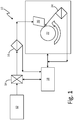
- FIG. 1 is a schematic diagram of feedback-controlled cryogenic machining system 10.
- System 10 includes pressurized cryogenic fluid source 12, flow regulator 14, sensor 16, machining control unit (MCU) 18, cutting tool 20, work piece 22, and infrared (IR) sensor 24.
- Cryogenic fluid source 12 is connected to flow regulator 14 via piping or tubing.
- Sensor 16 is attached to piping or tubing downstream of flow regulator 14, and cutting tool 20 is downstream of sensor 16.
- Cutting tool 20 machines work piece 22.
- IR sensor 24 is aimed at the intersection of cutting tool 20 and work piece 22.
- MCU 18 communicates with sensor 16 and IR sensor 24, and can control flow regulator 14, cutting tool 20, and work piece 22.
- cryogenic fluid source 12 In machining system 10, cutting tool 20 is cooled by a cryogenic fluid from cryogenic fluid source 12.
- Cryogenic coolants are typically liquefied gases, such as liquid nitrogen, hydrogen, or carbon dioxide. Liquid nitrogen is particularly useful for machining purposes as it can be used to chill a cutting tool without any environmental run off.
- Cryogenic fluid source 12 is a pressurized container holding a cryogenic fluid, such as liquid nitrogen, liquid carbon dioxide, or other cryogenic fluid used for cooling.
- Cryogenic fluid source 12 can be a Dewar flask or tank appropriate for holding a cryogenic coolant.
- Cryogenic fluid source 12 is connected to flow regulator 14, which controls the flow of cryogenic fluid from cryogenic fluid source 12 and into the system.
- Flow regulator 14 can be, for instance, a valve system or a variable speed pump.
- Flow regulator 14 can be a hand set regulator, or automatically set by feedback control. Ideally, flow regulator 14 allows enough cryogenic fluid into the system to effectively cool cutting tool 20, but does not waste cryogenic fluid.
- Sensor 16 Downstream of flow regulator 14 are sensor 16.
- Sensor 16 can be one or more sensors configured to detect temperature, pressure, or flow rate of a cryogenic fluid that has flowed through flow regulator 14.
- Sensor 16 can be commercially available sensors, and can be in-line with the flow of cryogenic fluid. Sensor 16 should not obstruct flow of the cryogenic fluid. For instance, sensor 16 can clamp over tubing through which the cryogenic fluid flows.
- a pressure sensor can be configured to detect cryogenic fluid pressure and used to determine cryogenic feed line pulsations.
- a flow sensor can be configured to detect the flow rate of the cryogenic fluid and used to determine feed line pulsations. This information can help determine the optimal feed rate and properties of cryogenic fluid to cutting tool 20.
- Cutting tool 20 is downstream of sensor 16.
- Cutting tool 20 can be a drill, turning insert, tap, broach cutter, abrasive tool, endmill, or threadmill.
- Cutting tool 20 can be used to drill, press, cut or otherwise shape work piece 22.
- a coolant such as liquid nitrogen, can be applied to cutting tool 20 through two methods: internally, through the inside of cutting tool 20, or externally, through a nozzle to cutting tool 20.
- a cryogenic fluid cooling cutting tool 20 can flash into a gas as it hits cutting tool 20, as it enters cutting tool 20, or as it exits cutting tool 20.
- Machining system 10 can be used to change work piece 22 (a raw material, such as titanium alloys) into a desired shape. This is accomplished by a controlled material removal process altering work piece 22 with cutting tool 20. Instructions can be programmed through a user interface (not pictured) to direct the movement and action of cutting tool 20, and the placement and orientation of work piece 22.
- Cutting tool 20 works on a surface of work piece 22 to shape work piece 22.
- Infrared (IR) sensor 24 monitors the surface of work piece 22 and the end of cutting tool 20.
- IR sensor 24 is in close proximity to where cutting tool 20 is working on work piece 22.
- IR sensor 24 optically monitors this area (sometimes referred to as the "cut zone"), including cutting tool 20 and the surface of work piece 22, detecting temperature variations. Temperature variations detected at the cut zone can show the state of cutting tool 20 and work piece 22. If temperature variations are outside of an optimal range, the work of cutting tool 20 can be altered by changing position or the process parameters of cutting tool 20. Additionally, IR sensor 24 can be used to detect heat released from cutting tool 20 as it works on work piece 22. Data collected by IR sensor 24 is sent to Machining control unit 18.
- Machining control unit (MCU) 18 receives data from sensor 16 and IR sensor 24.
- MCU 18 can be an add-on to a larger machining control unit, which can be a computer numerical control or a more complex program designed to control the machining process as a whole.
- MCU 18 analyzes data, such as temperature, pressure, or flow rate data, from sensor 16. The control of temperature, pressure, and flow rate of the cryogenic fluid via flow regulator 14 prevents the cryogenic fluid from flashing to a gas before it cools cutting tool 20.
- MCU 18 can be programmed so each measured property has an ideal range, and MCU 18 can adjust flow regulator 14 as required based on the incoming data. These adjustments allow for an efficient use of cryogenic fluid to cool cutting tool 20, but do not allow waste of cryogenic fluid. These adjustments can be made by MCU 18 automatically, or MCU 18 can notify a user of system 10 that adjustments need to be made.
- MCU 18 can also analyze data provided by IR sensor 24 about cutting tool 20 and work piece 22, allowing for quantitative information on the state of cutting tool 20, including temperature change on the surface of work piece 22 being cut by cutting tool 20. This creates an environment where the user of machining system 10 is notified before cutting tool 20 is dulled, and increasing overall efficiency of the system.
- feedback-controlled cryogenic machining system 10 uses inline sensor 16 to analyze the cryogenic fluid being delivered to cutting tool 20, set bounds for ideal temperature, pressure, and flow of the cryogenic fluid, and uses and IR sensor 24 to analyze temperature changes on the surface of work piece 22 and cutting tool 20. This information allows immediate adjustments by MCU 18 to the system, while machining is taking place, to optimize both the cryogenic cooling and the cutting of the work piece.
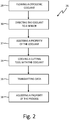
- FIG. 2 is a flow diagram of method 26 of using a feedback-controlled cryogenic machining system.
- Method 26 begins with step 28, where a cryogenic fluid, such as liquid nitrogen, is flowed into the system from a cryogenic fluid source through a flow regulator.
- the source can be a Dewar flask or tank suitable for storing cryogenic fluid.
- the flow regulator can be a valve system or variable speed pump that controls flow of cryogenic fluid out of the source.
- step 30 the cryogenic fluid is flowed through one or more in line sensors.
- step 32 the sensors assess temperature, pressure, flow rate, or any other metrics of interest. These properties show the state of the cryogenic fluid, and whether it is at ideal conditions or should be altered.
- the cryogenic fluid is then flowed to a cutting tool in step 34, where it cools the cutting tool.
- the cryogenic fluid can either be applied to an external surface of the cutting tool through a nozzle, or it can be applied to one or more internal passages of the cutting tool.
- the cutting tool's lifespan is greatly increased by the cryogenic cooling.
- IR infrared
- step 36 data from the sensors is sent to a machining control unit.
- the machining control unit analyzes the data, which can include temperature, pressure, and flow rate information about the cryogenic fluid, and determines which conditions should be altered to optimize the cryogenic cooling, avoid early flash of cryogenic fluid to a gas, and allow for less waste of cryogenic fluid.
- the machining control unit communicates with the flow regulator to adjust the flow of cryogenic fluid into the machining system, if needed.
- the machining control unit can also adjust the cutting tool position and machining process parameters.
- This feedback-controlled cryogenic machining system and method of using a feedback-controlled cryogenic machining system provide the user information regarding cryogenic fluid temperature, pressure and flow rate, all of which can be controlled by the feedback-controlled system.
- the system can make real-time adjustments based on the data it receives. This allows production yields which are better controlled and optimized, and provides real time data as machining processes are occurring.
- this method results in an increased lifespan of the cutting tool by more effectively cooling it, improved quality control of the work piece product by determining when the cutting tool should be replaced, improved efficiency of cooling the cutting tool with cryogenic fluid by wasting less cryogenic coolant, and long term data collection and analysis for use in future machining processes.
- a cryogenic machining system includes a cryogenic fluid source, a flow regulator downstream of the cryogenic fluid source, a machining control unit, at least one sensor downstream of the flow regulator, configured to assess cryogenic fluid and transmit data to the machining control unit, and a cutting tool downstream of the at least one sensor.
- the system of the preceding paragraph can optionally include, additionally and/or alternatively, any one or more of the following features, configurations and/or additional components:
- the at least one sensor is configured to assess flow velocity of the cryogenic fluid.
- the at least one sensor is configured to assess pressure of the cryogenic fluid at the at least one sensor.
- the at least one sensor is configured to assess temperature of the cryogenic fluid at the at least one sensor.
- the at least one sensor is an infrared sensor configured to assess the cryogenic fluid cooling the cutting tool.
- the at least one sensor configured to collect data relating to the cryogenic fluid.
- the at least one sensor configured to transmit data to the machining control unit.
- the machining control unit configured to control the flow regulator.
- the machining control unit configured to control the action and placement of the cutting tool.
- the machining control unit configured to control the movement and placement of the work piece.
- the cutting tool is internally cooled by the cryogenic fluid.
- the cutting tool is externally cooled by the cryogenic fluid.
- a method of regulating a cryogenically cooled machining system includes flowing a cryogenic coolant through a flow regulator; directing the cryogenic fluid through at least one sensor; assessing at least one property of the cryogenic fluid with the at least one sensor; cooling a cutting tool with the cryogenic coolant; transmitting data about the at least one property of the cryogenic fluid from the sensor to a machining control unit; and adjusting at least one property of the cryogenic coolant based on the data transmitted to the machining control unit.
- the method of the preceding paragraph can optionally include, additionally and/or alternatively, any one or more of the following features, configurations and/or additional components:
- the at least one property is pressure.
- the at least one property is flow velocity.
- the at least one property is infrared radiation.
- the method includes adjusting motion of the cutting tool based on the data transmitted to the machining control unit.
- the method includes adjusting placement of a work piece based on the data transmitted to the machining control unit.
Landscapes
- Engineering & Computer Science (AREA)
- Mechanical Engineering (AREA)
- Physics & Mathematics (AREA)
- Fluid Mechanics (AREA)
- Auxiliary Devices For Machine Tools (AREA)
- Automatic Control Of Machine Tools (AREA)
Abstract
Description
- Machining techniques take a raw material, called a work piece, and form it into a final, desired shape through a controlled material-removal process. Modem machining processes use a variety of cutting tools to shape work pieces, including drills, turning inserts, endmills, taps, threadmills, and others. These various tools can be used for machining such as turning, milling, hole making, cutting and other shaping processes.
- As cutting tools are used in machining processes, they are worn down. Over time, the application of cutting tools to work pieces dulls the tools. This is caused in part by the heat and friction created where the tool meets the work piece. Thus, cutting tools are often cooled to increase tool longevity.
- One such method of cooling cutting tools is cryogenic cooling. These methods utilize cryogenic coolants, such as liquid nitrogen or carbon dioxide, to cool the tool. Standard apparatuses for cryogenic cooling are commercially available. Some cryogenic machining systems run a coolant through the cutting tool. In contrast, other machining technology provides an external cooling scheme that applies coolant to the surface of the cutting tool. Both types of commercially available systems cool a tool used in machining methods.
- These methods offer no way to monitor how efficiently the cutting tool is being cooled by the cryogenic coolant. Neither do these methods provide any information on whether a cutting tool has dulled too much to be used, nor do these methods provide information on the state of the cryogenic fluid used in the process. Generally, these methods allow the cutting tool to be used until it no longer works, and allow users to only assess the cutting tool's condition in a qualitative, trial and error method. This causes error in work pieces when the cutting tool has deteriorated, and does not efficiently use cryogenic coolants.
- A cryogenic machining system includes a cryogenic fluid source, a flow regulator downstream of the cryogenic fluid source, a machining control unit, at least one sensor downstream of the flow regulator, configured to assess cryogenic fluid and transmit data to the machining control unit, and a cutting tool downstream of the at least one sensor.
- A method of regulating a cryogenically cooled machining system includes flowing a cryogenic coolant through a flow regulator; directing the cryogenic fluid through at least one sensor; assessing at least one property of the cryogenic fluid with the at least one sensor; cooling a cutting tool with the cryogenic coolant; transmitting data about the at least one property of the cryogenic fluid from the sensor to a machining control unit; and adjusting at least one property of the cryogenic coolant based on the data transmitted to the machining control unit.
-
-
FIG. 1 is a schematic diagram of a feedback-controlled cryogenic machining system. -
FIG. 2 is a flow diagram of a method of executing a feedback-controlled cryogenic machining system. - The disclosed system allows for a quantitative analysis of the state of a cutting tool and the cryogenic coolant flowing to a cutting tool. A feedback-controlled system provides data and information on the cutting tool and the cryogenic coolant not previously collected in machining systems. This information allows for modification of the cryogenic cooling machining system to create longer tool life, improved workpiece metallurgy and surface finish, and more efficient use of cryogenic coolants.
-
FIG. 1 is a schematic diagram of feedback-controlledcryogenic machining system 10.System 10 includes pressurizedcryogenic fluid source 12,flow regulator 14,sensor 16, machining control unit (MCU) 18,cutting tool 20,work piece 22, and infrared (IR)sensor 24.Cryogenic fluid source 12 is connected toflow regulator 14 via piping or tubing.Sensor 16 is attached to piping or tubing downstream offlow regulator 14, andcutting tool 20 is downstream ofsensor 16.Cutting tool 20machines work piece 22.IR sensor 24 is aimed at the intersection ofcutting tool 20 andwork piece 22.MCU 18 communicates withsensor 16 andIR sensor 24, and can controlflow regulator 14,cutting tool 20, andwork piece 22. - In
machining system 10,cutting tool 20 is cooled by a cryogenic fluid fromcryogenic fluid source 12. Cryogenic coolants are typically liquefied gases, such as liquid nitrogen, hydrogen, or carbon dioxide. Liquid nitrogen is particularly useful for machining purposes as it can be used to chill a cutting tool without any environmental run off.Cryogenic fluid source 12 is a pressurized container holding a cryogenic fluid, such as liquid nitrogen, liquid carbon dioxide, or other cryogenic fluid used for cooling.Cryogenic fluid source 12 can be a Dewar flask or tank appropriate for holding a cryogenic coolant. -
Cryogenic fluid source 12 is connected toflow regulator 14, which controls the flow of cryogenic fluid fromcryogenic fluid source 12 and into the system.Flow regulator 14 can be, for instance, a valve system or a variable speed pump.Flow regulator 14 can be a hand set regulator, or automatically set by feedback control. Ideally,flow regulator 14 allows enough cryogenic fluid into the system to effectively coolcutting tool 20, but does not waste cryogenic fluid. - Downstream of
flow regulator 14 aresensor 16.Sensor 16 can be one or more sensors configured to detect temperature, pressure, or flow rate of a cryogenic fluid that has flowed throughflow regulator 14.Sensor 16 can be commercially available sensors, and can be in-line with the flow of cryogenic fluid.Sensor 16 should not obstruct flow of the cryogenic fluid. For instance,sensor 16 can clamp over tubing through which the cryogenic fluid flows. -
Sensor 16 should be capable of detecting whether the cryogenic fluids' attributes fall outside of an optimal range for the cryogenic fluid. A pressure sensor can be configured to detect cryogenic fluid pressure and used to determine cryogenic feed line pulsations. A flow sensor can be configured to detect the flow rate of the cryogenic fluid and used to determine feed line pulsations. This information can help determine the optimal feed rate and properties of cryogenic fluid to cuttingtool 20. -
Cutting tool 20 is downstream ofsensor 16.Cutting tool 20 can be a drill, turning insert, tap, broach cutter, abrasive tool, endmill, or threadmill.Cutting tool 20 can be used to drill, press, cut or otherwise shapework piece 22. A coolant, such as liquid nitrogen, can be applied to cuttingtool 20 through two methods: internally, through the inside ofcutting tool 20, or externally, through a nozzle to cuttingtool 20. Depending on the needs of the specific system, a cryogenic fluidcooling cutting tool 20 can flash into a gas as it hitscutting tool 20, as it enterscutting tool 20, or as it exitscutting tool 20. -
Machining system 10 can be used to change work piece 22 (a raw material, such as titanium alloys) into a desired shape. This is accomplished by a controlled material removal process alteringwork piece 22 withcutting tool 20. Instructions can be programmed through a user interface (not pictured) to direct the movement and action ofcutting tool 20, and the placement and orientation ofwork piece 22. -
Cutting tool 20 works on a surface ofwork piece 22 to shapework piece 22. Infrared (IR)sensor 24 monitors the surface ofwork piece 22 and the end ofcutting tool 20.IR sensor 24 is in close proximity to wherecutting tool 20 is working onwork piece 22.IR sensor 24 optically monitors this area (sometimes referred to as the "cut zone"), includingcutting tool 20 and the surface ofwork piece 22, detecting temperature variations. Temperature variations detected at the cut zone can show the state of cuttingtool 20 andwork piece 22. If temperature variations are outside of an optimal range, the work of cuttingtool 20 can be altered by changing position or the process parameters of cuttingtool 20. Additionally,IR sensor 24 can be used to detect heat released from cuttingtool 20 as it works onwork piece 22. Data collected byIR sensor 24 is sent toMachining control unit 18. - Machining control unit (MCU) 18 receives data from
sensor 16 andIR sensor 24.MCU 18 can be an add-on to a larger machining control unit, which can be a computer numerical control or a more complex program designed to control the machining process as a whole.MCU 18 analyzes data, such as temperature, pressure, or flow rate data, fromsensor 16. The control of temperature, pressure, and flow rate of the cryogenic fluid viaflow regulator 14 prevents the cryogenic fluid from flashing to a gas before it cools cuttingtool 20. -
MCU 18 can be programmed so each measured property has an ideal range, andMCU 18 can adjustflow regulator 14 as required based on the incoming data. These adjustments allow for an efficient use of cryogenic fluid to cool cuttingtool 20, but do not allow waste of cryogenic fluid. These adjustments can be made byMCU 18 automatically, orMCU 18 can notify a user ofsystem 10 that adjustments need to be made. -
MCU 18 can also analyze data provided byIR sensor 24 about cuttingtool 20 andwork piece 22, allowing for quantitative information on the state of cuttingtool 20, including temperature change on the surface ofwork piece 22 being cut by cuttingtool 20. This creates an environment where the user ofmachining system 10 is notified before cuttingtool 20 is dulled, and increasing overall efficiency of the system. - Overall, feedback-controlled
cryogenic machining system 10 usesinline sensor 16 to analyze the cryogenic fluid being delivered to cuttingtool 20, set bounds for ideal temperature, pressure, and flow of the cryogenic fluid, and uses andIR sensor 24 to analyze temperature changes on the surface ofwork piece 22 and cuttingtool 20. This information allows immediate adjustments byMCU 18 to the system, while machining is taking place, to optimize both the cryogenic cooling and the cutting of the work piece. -
FIG. 2 is a flow diagram ofmethod 26 of using a feedback-controlled cryogenic machining system.Method 26 begins withstep 28, where a cryogenic fluid, such as liquid nitrogen, is flowed into the system from a cryogenic fluid source through a flow regulator. The source can be a Dewar flask or tank suitable for storing cryogenic fluid. The flow regulator can be a valve system or variable speed pump that controls flow of cryogenic fluid out of the source. - In
step 30, the cryogenic fluid is flowed through one or more in line sensors. Instep 32, the sensors assess temperature, pressure, flow rate, or any other metrics of interest. These properties show the state of the cryogenic fluid, and whether it is at ideal conditions or should be altered. - The cryogenic fluid is then flowed to a cutting tool in
step 34, where it cools the cutting tool. The cryogenic fluid can either be applied to an external surface of the cutting tool through a nozzle, or it can be applied to one or more internal passages of the cutting tool. The cutting tool's lifespan is greatly increased by the cryogenic cooling. - While the cryogenic fluid is cooling the cutting tool, another sensor can be monitoring the work of the cutting tool on a work piece. This sensor can be an infrared (IR) sensor which monitors heat given off by both the cutting tool and the surface of the work piece. The data collected from the IR sensor can determine whether the flow of the cryogenic fluid is optimal for tool life, machining process parameters and for producing acceptable surface finish and metallurgy.
- In
step 36, data from the sensors is sent to a machining control unit. The machining control unit analyzes the data, which can include temperature, pressure, and flow rate information about the cryogenic fluid, and determines which conditions should be altered to optimize the cryogenic cooling, avoid early flash of cryogenic fluid to a gas, and allow for less waste of cryogenic fluid. - Finally, in
step 38, the machining control unit communicates with the flow regulator to adjust the flow of cryogenic fluid into the machining system, if needed. The machining control unit can also adjust the cutting tool position and machining process parameters. - This feedback-controlled cryogenic machining system and method of using a feedback-controlled cryogenic machining system provide the user information regarding cryogenic fluid temperature, pressure and flow rate, all of which can be controlled by the feedback-controlled system. The system can make real-time adjustments based on the data it receives. This allows production yields which are better controlled and optimized, and provides real time data as machining processes are occurring.
- Overall, this method results in an increased lifespan of the cutting tool by more effectively cooling it, improved quality control of the work piece product by determining when the cutting tool should be replaced, improved efficiency of cooling the cutting tool with cryogenic fluid by wasting less cryogenic coolant, and long term data collection and analysis for use in future machining processes.
- The following are non-exclusive descriptions of possible embodiments of the present invention.
- A cryogenic machining system includes a cryogenic fluid source, a flow regulator downstream of the cryogenic fluid source, a machining control unit, at least one sensor downstream of the flow regulator, configured to assess cryogenic fluid and transmit data to the machining control unit, and a cutting tool downstream of the at least one sensor.
- The system of the preceding paragraph can optionally include, additionally and/or alternatively, any one or more of the following features, configurations and/or additional components:
- The system includes a work piece, wherein the cutting tool is configured to shape the work piece.
- The at least one sensor is configured to assess flow velocity of the cryogenic fluid.
- The at least one sensor is configured to assess pressure of the cryogenic fluid at the at least one sensor.
- The at least one sensor is configured to assess temperature of the cryogenic fluid at the at least one sensor.
- The at least one sensor is an infrared sensor configured to assess the cryogenic fluid cooling the cutting tool.
- The at least one sensor configured to collect data relating to the cryogenic fluid.
- The at least one sensor configured to transmit data to the machining control unit.
- The machining control unit configured to control the flow regulator.
- The machining control unit configured to control the action and placement of the cutting tool.
- The machining control unit configured to control the movement and placement of the work piece.
- The cutting tool is internally cooled by the cryogenic fluid.
- The cutting tool is externally cooled by the cryogenic fluid.
- A method of regulating a cryogenically cooled machining system includes flowing a cryogenic coolant through a flow regulator; directing the cryogenic fluid through at least one sensor; assessing at least one property of the cryogenic fluid with the at least one sensor; cooling a cutting tool with the cryogenic coolant; transmitting data about the at least one property of the cryogenic fluid from the sensor to a machining control unit; and adjusting at least one property of the cryogenic coolant based on the data transmitted to the machining control unit.
- The method of the preceding paragraph can optionally include, additionally and/or alternatively, any one or more of the following features, configurations and/or additional components:
- The at least one property is temperature.
- The at least one property is pressure.
- The at least one property is flow velocity.
- The at least one property is infrared radiation.
- The method includes adjusting motion of the cutting tool based on the data transmitted to the machining control unit.
- The method includes adjusting placement of a work piece based on the data transmitted to the machining control unit.
- While the invention has been described with reference to an exemplary embodiment(s), it will be understood by those skilled in the art that various changes can be made and equivalents can be substituted for elements thereof without departing from the scope of the invention. In addition, many modifications can be made to adapt a particular situation or material to the teachings of the invention without departing from the essential scope thereof. Therefore, it is intended that the invention not be limited to the particular embodiment(s) disclosed, but that the invention will include all embodiments falling within the scope of the appended claims.
Claims (15)
- A cryogenic machining system (10) comprising:a cryogenic fluid source (12);a flow regulator (14) downstream of the cryogenic fluid source (12);a machining control unit (18);at least one sensor (16) downstream of the flow regulator (14), the at least one sensor (16) configured to assess cryogenic fluid and transmit data to the machining control unit (18); anda cutting tool (20) downstream of the at least one sensor (16).
- The system (10) of claim 1 and further comprising a work piece (22), wherein the cutting tool (20) is configured to shape the work piece (22).
- The system (10) of claim 1 or 2, wherein the at least one sensor (16) is configured to assess one or more of flow rate, pressure or temperature of the cryogenic fluid.
- The system (10) of any preceding claim, wherein the at least one sensor (16) is an infrared sensor (24) configured to assess the cutting tool (20).
- The system (10) of any preceding claim, wherein the at least one sensor (16) is configured to collect data relating to the cryogenic fluid.
- The system (10) of any preceding claim, wherein the machining control unit (18) is configured to control the flow regulator (14).
- The system (10) of any preceding claim, wherein the machining control unit (18) is configured to control action and placement of the cutting tool (20).
- The system (10) of any of claims 2 to 7, wherein the machining control unit (18) is configured to control movement and placement of the work piece (22).
- The system (10) of any preceding claim, wherein the cutting tool (20) is internally cooled by the cryogenic fluid.
- The system (10) of any preceding claim, wherein the cutting tool (20) is externally cooled by the cryogenic fluid.
- A method (26) of regulating a cryogenically cooled machining system (10), the method (26) comprising:flowing a cryogenic coolant through a flow regulator (14);directing the cryogenic fluid through at least one sensor (16);assessing at least one property of the cryogenic fluid with the at least one sensor (16);cooling a cutting tool (20) with the cryogenic coolant;transmitting data about the at least one property of the cryogenic fluid from the sensor (16) to a machining control unit (18); andadjusting at least one property of the cryogenic coolant based on the data transmitted to the machining control unit (18).
- The method (26) of claim 11, wherein the at least one property is at least one of temperature, pressure and/or flow velocity.
- The method (26) of claim 11 or 12, further comprising detecting infrared radiation near the cutting tool (20).
- The method (26) of any of claims 11 to 13, further comprising adjusting motion of the cutting tool (20) based on the data transmitted to the machining control unit (18).
- The method (26) of any of claims 11 to 14, further comprising adjusting placement of a work piece (22) based on the data transmitted to the machining control unit (18).
Applications Claiming Priority (1)
| Application Number | Priority Date | Filing Date | Title |
|---|---|---|---|
| US15/296,609 US20180104750A1 (en) | 2016-10-18 | 2016-10-18 | Feedback-controlled system for cyrogenically cooling machining tools |
Publications (2)
| Publication Number | Publication Date |
|---|---|
| EP3311953A1 true EP3311953A1 (en) | 2018-04-25 |
| EP3311953B1 EP3311953B1 (en) | 2022-03-02 |
Family
ID=59901385
Family Applications (1)
| Application Number | Title | Priority Date | Filing Date |
|---|---|---|---|
| EP17191183.7A Active EP3311953B1 (en) | 2016-10-18 | 2017-09-14 | Feedback-controlled system for cryogenically cooling machining tools |
Country Status (2)
| Country | Link |
|---|---|
| US (1) | US20180104750A1 (en) |
| EP (1) | EP3311953B1 (en) |
Cited By (1)
| Publication number | Priority date | Publication date | Assignee | Title |
|---|---|---|---|---|
| CN109262366A (en) * | 2018-10-25 | 2019-01-25 | 广州小乙科技有限公司 | A kind of location type high-speed drilling tooth machining unit with lubrication system |
Families Citing this family (4)
| Publication number | Priority date | Publication date | Assignee | Title |
|---|---|---|---|---|
| US10786853B2 (en) | 2018-06-28 | 2020-09-29 | United Technologies Corporation | Cooling system for rotating cutting tools |
| CN109048485A (en) * | 2018-10-11 | 2018-12-21 | 济南大学 | A kind of liquid nitrogen flow intelligent control cooling system suitable for sub-zero machining |
| FR3095153B1 (en) * | 2019-04-18 | 2021-11-26 | Air Liquide France Ind | Process for supplying cryogenic fluid to a machining machine |
| CN112496363A (en) * | 2020-11-24 | 2021-03-16 | 南京航空航天大学 | Low-temperature system for low-temperature cutting machining and using method thereof |
Citations (7)
| Publication number | Priority date | Publication date | Assignee | Title |
|---|---|---|---|---|
| WO2002096598A1 (en) * | 2001-05-31 | 2002-12-05 | Air Products And Chemicals, Inc. | An apparatus and method for machining with cryogenically cooled oxide-containing ceramic cutting tools |
| WO2009032709A1 (en) * | 2007-08-28 | 2009-03-12 | Air Products And Chemicals, Inc. | Apparatus and method for controlling the temperature of a cryogen |
| EP2347855A1 (en) * | 2010-01-26 | 2011-07-27 | University of Ljubljana | System and method for delivery of liquid cryogenic fluid to machining tools |
| EP2353779A1 (en) * | 2010-02-05 | 2011-08-10 | University of Ljubljana | Cutting tool holder arrangement |
| EP2572825A2 (en) * | 2011-09-23 | 2013-03-27 | United Technologies Corporation | Strengthening by machining |
| DE202013007344U1 (en) * | 2013-08-14 | 2013-09-12 | Ake Knebel Gmbh & Co. Kg | Thermal control for a cutting machine tool |
| WO2015044124A1 (en) * | 2013-09-30 | 2015-04-02 | University Of Ljubljana | Optical sensor arrangement for monitoring cryogenic fluid |
Family Cites Families (33)
| Publication number | Priority date | Publication date | Assignee | Title |
|---|---|---|---|---|
| US7246A (en) * | 1850-04-02 | Blind and shutter opener and fastener | ||
| GB820308A (en) * | 1955-02-25 | 1959-09-16 | Nat Res Dev | Improvements in or relating to controlling the supply of carbon dioxide and like coolants to cutting tools |
| US3889520A (en) * | 1973-02-13 | 1975-06-17 | Theodor Stoferle | Fluidic system for monitoring machine tool wear during a machining operation |
| US4417489A (en) * | 1979-12-21 | 1983-11-29 | Liu Chunghorng R | Method and apparatus for machining a workpiece by varying the tool geometry |
| DE3042211A1 (en) * | 1980-11-08 | 1982-05-19 | Feldmühle AG, 4000 Düsseldorf | METHOD AND DEVICE FOR MONITORING THE INSERT IN TOOLING MACHINES |
| US5387061A (en) * | 1990-12-14 | 1995-02-07 | The United States Of America As Represented By The United States Department Of Energy | Parameter monitoring compensation system and method |
| JPH04242742A (en) * | 1990-12-28 | 1992-08-31 | Konica Corp | Surface treatment method of electrophotographic photoconductor substrate |
| DE4233035C1 (en) * | 1992-10-01 | 1993-07-22 | Daimler-Benz Aktiengesellschaft, 7000 Stuttgart, De | Temperature measurement appts. for cutting tool - contains channel for thermal radiation in cutting tool, diamond covered opening, thermal camera |
| US6161055A (en) * | 1993-05-17 | 2000-12-12 | Laser Measurement International Inc. | Method of determining tool breakage |
| US5509335A (en) * | 1994-02-25 | 1996-04-23 | Value Tech Engineering, Inc. | Cryogenic vapor oxygen free machining method |
| US5522707A (en) * | 1994-11-16 | 1996-06-04 | Metropolitan Industries, Inc. | Variable frequency drive system for fluid delivery system |
| EP1112134B1 (en) * | 1998-09-08 | 2005-07-27 | Makino, Inc. | Tool with control of a fluid axis |
| DE10006727A1 (en) * | 2000-02-15 | 2001-08-23 | Daimler Chrysler Ag | Device for temperature measurement during machining process has channel in machining plate support feeding heat from temperature measurement point to temperature measurement device |
| EP1199126A4 (en) * | 2000-03-03 | 2002-11-20 | Masao Murakawa | ANTI-CALORIE DISPOSABLE TIP AND ANTI-CALORIE DISPOSABLE TOOL HAVING SUCH A DISPOSABLE POINT |
| US6564682B1 (en) * | 2000-11-14 | 2003-05-20 | Air Products And Chemicals, Inc. | Machine tool distributor for cryogenic cooling of cutting tools on a turret plate |
| US20030110781A1 (en) * | 2001-09-13 | 2003-06-19 | Zbigniew Zurecki | Apparatus and method of cryogenic cooling for high-energy cutting operations |
| US6874977B2 (en) * | 2002-02-04 | 2005-04-05 | Morrell Incorporated | High pressure coolant system |
| US20060011002A1 (en) * | 2004-07-13 | 2006-01-19 | Rashleger Timothy L | Machine tool with dimensional change compensation |
| WO2006065838A2 (en) * | 2004-12-13 | 2006-06-22 | Cool Clean Technologies, Inc. | Device for applying cryogenic composition and method of using same |
| DE102008013390B4 (en) * | 2007-03-09 | 2019-03-07 | Hartmut Rieger | Nozzle for the joint spraying of two different, liquid media |
| US20090320655A1 (en) * | 2008-06-30 | 2009-12-31 | Marion Billingsley Grant | Machining tool utilizing a supercritical coolant |
| DE102008044401A1 (en) * | 2008-12-05 | 2010-06-10 | Robert Bosch Gmbh | Power tool, particularly cutting power tool, has work piece overheating protection device working speed of power tool is regulated depending on work piece temperature in work piece working area |
| US8061241B2 (en) * | 2009-04-06 | 2011-11-22 | Creare Incorporated | Indirect cooling of a cutting tool |
| EP2388507A1 (en) * | 2010-05-19 | 2011-11-23 | MOOG GmbH | Lubrication and/or coolant system with adjustable flowrate for a machine tool |
| US8568198B2 (en) * | 2010-07-16 | 2013-10-29 | Pratt & Whitney Canada Corp. | Active coolant flow control for machining processes |
| DE102011003005A1 (en) * | 2011-01-21 | 2012-07-26 | Mag Ias Gmbh | Tool turret for machining workpieces and machining system with such a tool turret |
| US9616540B2 (en) * | 2011-02-08 | 2017-04-11 | The University Of Utah Research Foundation | System and method for dispensing a minimum quantity of cutting fluid |
| WO2012129138A2 (en) * | 2011-03-18 | 2012-09-27 | Cool Clean Technologies, Inc. | Method and apparatus for thermal control within a machining process |
| DE202011052170U1 (en) * | 2011-12-02 | 2013-03-04 | Brinkmann Pumpen K.H. Brinkmann Gmbh & Co. Kg | Coolant system for machine tools |
| DE102013203670A1 (en) * | 2013-03-04 | 2014-09-04 | Index-Werke Gmbh & Co. Kg Hahn & Tessky | machine tool |
| DE102013215057A1 (en) * | 2013-07-31 | 2015-02-05 | Mag Ias Gmbh | Tool spindle for machining workpieces and associated machining tool and machining device with such a tool spindle and method for machining workpieces |
| JP6424582B2 (en) * | 2014-11-25 | 2018-11-21 | 株式会社デンソー | Cutting apparatus and cutting method |
| US10007246B2 (en) * | 2014-12-02 | 2018-06-26 | Caterpillar Inc. | Machining tool utilizing a supercritical coolant |
-
2016
- 2016-10-18 US US15/296,609 patent/US20180104750A1/en not_active Abandoned
-
2017
- 2017-09-14 EP EP17191183.7A patent/EP3311953B1/en active Active
Patent Citations (7)
| Publication number | Priority date | Publication date | Assignee | Title |
|---|---|---|---|---|
| WO2002096598A1 (en) * | 2001-05-31 | 2002-12-05 | Air Products And Chemicals, Inc. | An apparatus and method for machining with cryogenically cooled oxide-containing ceramic cutting tools |
| WO2009032709A1 (en) * | 2007-08-28 | 2009-03-12 | Air Products And Chemicals, Inc. | Apparatus and method for controlling the temperature of a cryogen |
| EP2347855A1 (en) * | 2010-01-26 | 2011-07-27 | University of Ljubljana | System and method for delivery of liquid cryogenic fluid to machining tools |
| EP2353779A1 (en) * | 2010-02-05 | 2011-08-10 | University of Ljubljana | Cutting tool holder arrangement |
| EP2572825A2 (en) * | 2011-09-23 | 2013-03-27 | United Technologies Corporation | Strengthening by machining |
| DE202013007344U1 (en) * | 2013-08-14 | 2013-09-12 | Ake Knebel Gmbh & Co. Kg | Thermal control for a cutting machine tool |
| WO2015044124A1 (en) * | 2013-09-30 | 2015-04-02 | University Of Ljubljana | Optical sensor arrangement for monitoring cryogenic fluid |
Cited By (2)
| Publication number | Priority date | Publication date | Assignee | Title |
|---|---|---|---|---|
| CN109262366A (en) * | 2018-10-25 | 2019-01-25 | 广州小乙科技有限公司 | A kind of location type high-speed drilling tooth machining unit with lubrication system |
| CN109262366B (en) * | 2018-10-25 | 2020-04-07 | 江苏元奕朗甚装饰工程有限公司 | Positioning type high-speed drilling and tapping machine with lubricating structure |
Also Published As
| Publication number | Publication date |
|---|---|
| EP3311953B1 (en) | 2022-03-02 |
| US20180104750A1 (en) | 2018-04-19 |
Similar Documents
| Publication | Publication Date | Title |
|---|---|---|
| EP3311953B1 (en) | Feedback-controlled system for cryogenically cooling machining tools | |
| US20200230770A1 (en) | Feedback-controlled system for cyrogenically cooling machining tools | |
| US9931724B2 (en) | System and method for dispensing a minimum quantity of cutting fluid | |
| CN110058621B (en) | Liquid nitrogen injection amount on-line control method for ultralow temperature cooling processing | |
| Klocke et al. | Influence of a high-pressure lubricoolant supply on thermo-mechanical tool load and tool wear behaviour in the turning of aerospace materials | |
| CN109202524A (en) | A kind of numerically-controlled machine tool cutting adjustable Intelligent cooling device of flow quantity | |
| EP3587031B1 (en) | Cooling system for rotating cutting tools | |
| CN109249275A (en) | A coolant flow adjustable device for CNC machine tools | |
| JP5230939B2 (en) | Aerosol generation method and apparatus | |
| Klocke et al. | Potential of modern lubricoolant strategies on cutting performance | |
| KR101742300B1 (en) | Computerized numerical control lath having function of temperature control | |
| CN209007207U (en) | The adjustable cooling device of intelligence is carried out for numerical control machine tool cutting flow quantity | |
| US10610992B2 (en) | Automated interchangeable coolant distributor | |
| CN206185509U (en) | A device for processing deep blind hole inner groove | |
| Mahapatro et al. | Performance study of carbon dioxide–based vortex tube cooling system in turning of Ti-6Al-4V | |
| CN210968038U (en) | Chip removal cooling device of numerically controlled fraise machine | |
| Pathan et al. | Experimental study on effect of cutting parameters on chip-tool interface temperature and chip formation in turning en-31 hardened steel under flooded and mql conditions | |
| CN207508829U (en) | A kind of machining center intelligently cools down debris removal system | |
| CN121398929A (en) | Machine tool for workpiece machining, hydraulic device, hydraulic system and workpiece machining method | |
| CN110936221A (en) | Processing cooling system of heterogeneous material | |
| CN207223524U (en) | A kind of cutting fluid remains blowning installation | |
| CN103949669A (en) | Milling machine with internal circulation cooling system | |
| CN113784818B (en) | Method for supplying cryogenic fluid to a machining machine | |
| CN121649487A (en) | A process for machining liquid-cooled spade teeth | |
| CN206966673U (en) | A kind of numerically controlled lathe cutter heat sink |
Legal Events
| Date | Code | Title | Description |
|---|---|---|---|
| PUAI | Public reference made under article 153(3) epc to a published international application that has entered the european phase |
Free format text: ORIGINAL CODE: 0009012 |
|
| STAA | Information on the status of an ep patent application or granted ep patent |
Free format text: STATUS: THE APPLICATION HAS BEEN PUBLISHED |
|
| AK | Designated contracting states |
Kind code of ref document: A1 Designated state(s): AL AT BE BG CH CY CZ DE DK EE ES FI FR GB GR HR HU IE IS IT LI LT LU LV MC MK MT NL NO PL PT RO RS SE SI SK SM TR |
|
| AX | Request for extension of the european patent |
Extension state: BA ME |
|
| STAA | Information on the status of an ep patent application or granted ep patent |
Free format text: STATUS: REQUEST FOR EXAMINATION WAS MADE |
|
| 17P | Request for examination filed |
Effective date: 20181025 |
|
| RBV | Designated contracting states (corrected) |
Designated state(s): AL AT BE BG CH CY CZ DE DK EE ES FI FR GB GR HR HU IE IS IT LI LT LU LV MC MK MT NL NO PL PT RO RS SE SI SK SM TR |
|
| STAA | Information on the status of an ep patent application or granted ep patent |
Free format text: STATUS: EXAMINATION IS IN PROGRESS |
|
| 17Q | First examination report despatched |
Effective date: 20201216 |
|
| RAP1 | Party data changed (applicant data changed or rights of an application transferred) |
Owner name: RAYTHEON TECHNOLOGIES CORPORATION |
|
| GRAP | Despatch of communication of intention to grant a patent |
Free format text: ORIGINAL CODE: EPIDOSNIGR1 |
|
| STAA | Information on the status of an ep patent application or granted ep patent |
Free format text: STATUS: GRANT OF PATENT IS INTENDED |
|
| INTG | Intention to grant announced |
Effective date: 20210920 |
|
| GRAS | Grant fee paid |
Free format text: ORIGINAL CODE: EPIDOSNIGR3 |
|
| GRAA | (expected) grant |
Free format text: ORIGINAL CODE: 0009210 |
|
| STAA | Information on the status of an ep patent application or granted ep patent |
Free format text: STATUS: THE PATENT HAS BEEN GRANTED |
|
| AK | Designated contracting states |
Kind code of ref document: B1 Designated state(s): AL AT BE BG CH CY CZ DE DK EE ES FI FR GB GR HR HU IE IS IT LI LT LU LV MC MK MT NL NO PL PT RO RS SE SI SK SM TR |
|
| REG | Reference to a national code |
Ref country code: GB Ref legal event code: FG4D |
|
| REG | Reference to a national code |
Ref country code: CH Ref legal event code: EP Ref country code: AT Ref legal event code: REF Ref document number: 1471866 Country of ref document: AT Kind code of ref document: T Effective date: 20220315 |
|
| REG | Reference to a national code |
Ref country code: DE Ref legal event code: R096 Ref document number: 602017053946 Country of ref document: DE |
|
| REG | Reference to a national code |
Ref country code: IE Ref legal event code: FG4D |
|
| REG | Reference to a national code |
Ref country code: LT Ref legal event code: MG9D |
|
| REG | Reference to a national code |
Ref country code: NL Ref legal event code: MP Effective date: 20220302 |
|
| PG25 | Lapsed in a contracting state [announced via postgrant information from national office to epo] |
Ref country code: SE Free format text: LAPSE BECAUSE OF FAILURE TO SUBMIT A TRANSLATION OF THE DESCRIPTION OR TO PAY THE FEE WITHIN THE PRESCRIBED TIME-LIMIT Effective date: 20220302 Ref country code: RS Free format text: LAPSE BECAUSE OF FAILURE TO SUBMIT A TRANSLATION OF THE DESCRIPTION OR TO PAY THE FEE WITHIN THE PRESCRIBED TIME-LIMIT Effective date: 20220302 Ref country code: NO Free format text: LAPSE BECAUSE OF FAILURE TO SUBMIT A TRANSLATION OF THE DESCRIPTION OR TO PAY THE FEE WITHIN THE PRESCRIBED TIME-LIMIT Effective date: 20220602 Ref country code: LT Free format text: LAPSE BECAUSE OF FAILURE TO SUBMIT A TRANSLATION OF THE DESCRIPTION OR TO PAY THE FEE WITHIN THE PRESCRIBED TIME-LIMIT Effective date: 20220302 Ref country code: HR Free format text: LAPSE BECAUSE OF FAILURE TO SUBMIT A TRANSLATION OF THE DESCRIPTION OR TO PAY THE FEE WITHIN THE PRESCRIBED TIME-LIMIT Effective date: 20220302 Ref country code: ES Free format text: LAPSE BECAUSE OF FAILURE TO SUBMIT A TRANSLATION OF THE DESCRIPTION OR TO PAY THE FEE WITHIN THE PRESCRIBED TIME-LIMIT Effective date: 20220302 Ref country code: BG Free format text: LAPSE BECAUSE OF FAILURE TO SUBMIT A TRANSLATION OF THE DESCRIPTION OR TO PAY THE FEE WITHIN THE PRESCRIBED TIME-LIMIT Effective date: 20220602 |
|
| REG | Reference to a national code |
Ref country code: AT Ref legal event code: MK05 Ref document number: 1471866 Country of ref document: AT Kind code of ref document: T Effective date: 20220302 |
|
| PG25 | Lapsed in a contracting state [announced via postgrant information from national office to epo] |
Ref country code: PL Free format text: LAPSE BECAUSE OF FAILURE TO SUBMIT A TRANSLATION OF THE DESCRIPTION OR TO PAY THE FEE WITHIN THE PRESCRIBED TIME-LIMIT Effective date: 20220302 Ref country code: LV Free format text: LAPSE BECAUSE OF FAILURE TO SUBMIT A TRANSLATION OF THE DESCRIPTION OR TO PAY THE FEE WITHIN THE PRESCRIBED TIME-LIMIT Effective date: 20220302 Ref country code: GR Free format text: LAPSE BECAUSE OF FAILURE TO SUBMIT A TRANSLATION OF THE DESCRIPTION OR TO PAY THE FEE WITHIN THE PRESCRIBED TIME-LIMIT Effective date: 20220603 Ref country code: FI Free format text: LAPSE BECAUSE OF FAILURE TO SUBMIT A TRANSLATION OF THE DESCRIPTION OR TO PAY THE FEE WITHIN THE PRESCRIBED TIME-LIMIT Effective date: 20220302 |
|
| PG25 | Lapsed in a contracting state [announced via postgrant information from national office to epo] |
Ref country code: NL Free format text: LAPSE BECAUSE OF FAILURE TO SUBMIT A TRANSLATION OF THE DESCRIPTION OR TO PAY THE FEE WITHIN THE PRESCRIBED TIME-LIMIT Effective date: 20220302 |
|
| PG25 | Lapsed in a contracting state [announced via postgrant information from national office to epo] |
Ref country code: SM Free format text: LAPSE BECAUSE OF FAILURE TO SUBMIT A TRANSLATION OF THE DESCRIPTION OR TO PAY THE FEE WITHIN THE PRESCRIBED TIME-LIMIT Effective date: 20220302 Ref country code: SK Free format text: LAPSE BECAUSE OF FAILURE TO SUBMIT A TRANSLATION OF THE DESCRIPTION OR TO PAY THE FEE WITHIN THE PRESCRIBED TIME-LIMIT Effective date: 20220302 Ref country code: RO Free format text: LAPSE BECAUSE OF FAILURE TO SUBMIT A TRANSLATION OF THE DESCRIPTION OR TO PAY THE FEE WITHIN THE PRESCRIBED TIME-LIMIT Effective date: 20220302 Ref country code: PT Free format text: LAPSE BECAUSE OF FAILURE TO SUBMIT A TRANSLATION OF THE DESCRIPTION OR TO PAY THE FEE WITHIN THE PRESCRIBED TIME-LIMIT Effective date: 20220704 Ref country code: EE Free format text: LAPSE BECAUSE OF FAILURE TO SUBMIT A TRANSLATION OF THE DESCRIPTION OR TO PAY THE FEE WITHIN THE PRESCRIBED TIME-LIMIT Effective date: 20220302 Ref country code: CZ Free format text: LAPSE BECAUSE OF FAILURE TO SUBMIT A TRANSLATION OF THE DESCRIPTION OR TO PAY THE FEE WITHIN THE PRESCRIBED TIME-LIMIT Effective date: 20220302 Ref country code: AT Free format text: LAPSE BECAUSE OF FAILURE TO SUBMIT A TRANSLATION OF THE DESCRIPTION OR TO PAY THE FEE WITHIN THE PRESCRIBED TIME-LIMIT Effective date: 20220302 |
|
| PG25 | Lapsed in a contracting state [announced via postgrant information from national office to epo] |
Ref country code: IS Free format text: LAPSE BECAUSE OF FAILURE TO SUBMIT A TRANSLATION OF THE DESCRIPTION OR TO PAY THE FEE WITHIN THE PRESCRIBED TIME-LIMIT Effective date: 20220702 Ref country code: AL Free format text: LAPSE BECAUSE OF FAILURE TO SUBMIT A TRANSLATION OF THE DESCRIPTION OR TO PAY THE FEE WITHIN THE PRESCRIBED TIME-LIMIT Effective date: 20220302 |
|
| REG | Reference to a national code |
Ref country code: DE Ref legal event code: R097 Ref document number: 602017053946 Country of ref document: DE |
|
| PLBE | No opposition filed within time limit |
Free format text: ORIGINAL CODE: 0009261 |
|
| STAA | Information on the status of an ep patent application or granted ep patent |
Free format text: STATUS: NO OPPOSITION FILED WITHIN TIME LIMIT |
|
| PG25 | Lapsed in a contracting state [announced via postgrant information from national office to epo] |
Ref country code: DK Free format text: LAPSE BECAUSE OF FAILURE TO SUBMIT A TRANSLATION OF THE DESCRIPTION OR TO PAY THE FEE WITHIN THE PRESCRIBED TIME-LIMIT Effective date: 20220302 |
|
| 26N | No opposition filed |
Effective date: 20221205 |
|
| PG25 | Lapsed in a contracting state [announced via postgrant information from national office to epo] |
Ref country code: SI Free format text: LAPSE BECAUSE OF FAILURE TO SUBMIT A TRANSLATION OF THE DESCRIPTION OR TO PAY THE FEE WITHIN THE PRESCRIBED TIME-LIMIT Effective date: 20220302 |
|
| PG25 | Lapsed in a contracting state [announced via postgrant information from national office to epo] |
Ref country code: MC Free format text: LAPSE BECAUSE OF FAILURE TO SUBMIT A TRANSLATION OF THE DESCRIPTION OR TO PAY THE FEE WITHIN THE PRESCRIBED TIME-LIMIT Effective date: 20220302 |
|
| REG | Reference to a national code |
Ref country code: CH Ref legal event code: PL |
|
| REG | Reference to a national code |
Ref country code: BE Ref legal event code: MM Effective date: 20220930 |
|
| P01 | Opt-out of the competence of the unified patent court (upc) registered |
Effective date: 20230520 |
|
| PG25 | Lapsed in a contracting state [announced via postgrant information from national office to epo] |
Ref country code: LU Free format text: LAPSE BECAUSE OF NON-PAYMENT OF DUE FEES Effective date: 20220914 |
|
| PG25 | Lapsed in a contracting state [announced via postgrant information from national office to epo] |
Ref country code: LI Free format text: LAPSE BECAUSE OF NON-PAYMENT OF DUE FEES Effective date: 20220930 Ref country code: IT Free format text: LAPSE BECAUSE OF FAILURE TO SUBMIT A TRANSLATION OF THE DESCRIPTION OR TO PAY THE FEE WITHIN THE PRESCRIBED TIME-LIMIT Effective date: 20220302 Ref country code: IE Free format text: LAPSE BECAUSE OF NON-PAYMENT OF DUE FEES Effective date: 20220914 Ref country code: FR Free format text: LAPSE BECAUSE OF NON-PAYMENT OF DUE FEES Effective date: 20220930 Ref country code: CH Free format text: LAPSE BECAUSE OF NON-PAYMENT OF DUE FEES Effective date: 20220930 |
|
| PG25 | Lapsed in a contracting state [announced via postgrant information from national office to epo] |
Ref country code: BE Free format text: LAPSE BECAUSE OF NON-PAYMENT OF DUE FEES Effective date: 20220930 |
|
| PG25 | Lapsed in a contracting state [announced via postgrant information from national office to epo] |
Ref country code: HU Free format text: LAPSE BECAUSE OF FAILURE TO SUBMIT A TRANSLATION OF THE DESCRIPTION OR TO PAY THE FEE WITHIN THE PRESCRIBED TIME-LIMIT; INVALID AB INITIO Effective date: 20170914 |
|
| PG25 | Lapsed in a contracting state [announced via postgrant information from national office to epo] |
Ref country code: CY Free format text: LAPSE BECAUSE OF FAILURE TO SUBMIT A TRANSLATION OF THE DESCRIPTION OR TO PAY THE FEE WITHIN THE PRESCRIBED TIME-LIMIT Effective date: 20220302 |
|
| PG25 | Lapsed in a contracting state [announced via postgrant information from national office to epo] |
Ref country code: MK Free format text: LAPSE BECAUSE OF FAILURE TO SUBMIT A TRANSLATION OF THE DESCRIPTION OR TO PAY THE FEE WITHIN THE PRESCRIBED TIME-LIMIT Effective date: 20220302 |
|
| PG25 | Lapsed in a contracting state [announced via postgrant information from national office to epo] |
Ref country code: MT Free format text: LAPSE BECAUSE OF FAILURE TO SUBMIT A TRANSLATION OF THE DESCRIPTION OR TO PAY THE FEE WITHIN THE PRESCRIBED TIME-LIMIT Effective date: 20220302 |
|
| REG | Reference to a national code |
Ref country code: DE Ref legal event code: R081 Ref document number: 602017053946 Country of ref document: DE Owner name: RTX CORPORATION (N.D.GES.D. STAATES DELAWARE),, US Free format text: FORMER OWNER: RAYTHEON TECHNOLOGIES CORPORATION, FARMINGTON, CT, US |
|
| PGFP | Annual fee paid to national office [announced via postgrant information from national office to epo] |
Ref country code: DE Payment date: 20250820 Year of fee payment: 9 |
|
| PGFP | Annual fee paid to national office [announced via postgrant information from national office to epo] |
Ref country code: GB Payment date: 20250820 Year of fee payment: 9 |
|
| PG25 | Lapsed in a contracting state [announced via postgrant information from national office to epo] |
Ref country code: TR Free format text: LAPSE BECAUSE OF FAILURE TO SUBMIT A TRANSLATION OF THE DESCRIPTION OR TO PAY THE FEE WITHIN THE PRESCRIBED TIME-LIMIT Effective date: 20220302 |