EP3311896B1 - Entertainment-oriented multi-mode experience system - Google Patents
Entertainment-oriented multi-mode experience system Download PDFInfo
- Publication number
- EP3311896B1 EP3311896B1 EP15895328.1A EP15895328A EP3311896B1 EP 3311896 B1 EP3311896 B1 EP 3311896B1 EP 15895328 A EP15895328 A EP 15895328A EP 3311896 B1 EP3311896 B1 EP 3311896B1
- Authority
- EP
- European Patent Office
- Prior art keywords
- rail
- screen
- riding vehicle
- amusement
- experience system
- Prior art date
- Legal status (The legal status is an assumption and is not a legal conclusion. Google has not performed a legal analysis and makes no representation as to the accuracy of the status listed.)
- Active
Links
- 230000004936 stimulating effect Effects 0.000 claims description 22
- 230000001360 synchronised effect Effects 0.000 claims description 16
- 230000007246 mechanism Effects 0.000 claims description 12
- 230000003068 static effect Effects 0.000 claims description 4
- 230000001788 irregular Effects 0.000 claims description 3
- 238000000034 method Methods 0.000 description 4
- 230000001133 acceleration Effects 0.000 description 1
- 238000005034 decoration Methods 0.000 description 1
- 230000001419 dependent effect Effects 0.000 description 1
- 238000005516 engineering process Methods 0.000 description 1
- 230000002093 peripheral effect Effects 0.000 description 1
Images


Classifications
-
- A—HUMAN NECESSITIES
- A63—SPORTS; GAMES; AMUSEMENTS
- A63G—MERRY-GO-ROUNDS; SWINGS; ROCKING-HORSES; CHUTES; SWITCHBACKS; SIMILAR DEVICES FOR PUBLIC AMUSEMENT
- A63G21/00—Chutes; Helter-skelters
- A63G21/04—Chutes; Helter-skelters with fixed rails
-
- A—HUMAN NECESSITIES
- A63—SPORTS; GAMES; AMUSEMENTS
- A63G—MERRY-GO-ROUNDS; SWINGS; ROCKING-HORSES; CHUTES; SWITCHBACKS; SIMILAR DEVICES FOR PUBLIC AMUSEMENT
- A63G7/00—Up-and-down hill tracks; Switchbacks
-
- A—HUMAN NECESSITIES
- A63—SPORTS; GAMES; AMUSEMENTS
- A63G—MERRY-GO-ROUNDS; SWINGS; ROCKING-HORSES; CHUTES; SWITCHBACKS; SIMILAR DEVICES FOR PUBLIC AMUSEMENT
- A63G21/00—Chutes; Helter-skelters
- A63G21/06—Chutes; Helter-skelters with passing arrangements for cars
-
- A—HUMAN NECESSITIES
- A63—SPORTS; GAMES; AMUSEMENTS
- A63G—MERRY-GO-ROUNDS; SWINGS; ROCKING-HORSES; CHUTES; SWITCHBACKS; SIMILAR DEVICES FOR PUBLIC AMUSEMENT
- A63G25/00—Autocar-like self-drivers; Runways therefor
-
- A—HUMAN NECESSITIES
- A63—SPORTS; GAMES; AMUSEMENTS
- A63G—MERRY-GO-ROUNDS; SWINGS; ROCKING-HORSES; CHUTES; SWITCHBACKS; SIMILAR DEVICES FOR PUBLIC AMUSEMENT
- A63G31/00—Amusement arrangements
- A63G31/02—Amusement arrangements with moving substructures
-
- A—HUMAN NECESSITIES
- A63—SPORTS; GAMES; AMUSEMENTS
- A63J—DEVICES FOR THEATRES, CIRCUSES, OR THE LIKE; CONJURING APPLIANCES OR THE LIKE
- A63J5/00—Auxiliaries for producing special effects on stages, or in circuses or arenas
- A63J5/02—Arrangements for making stage effects; Auxiliary stage appliances
- A63J5/025—Devices for making mist or smoke effects, e.g. with liquid air
Definitions
- the present disclosure generally relates to amusement systems, and more particularly, to amusement-oriented multi-mode experience systems.
- the rails of entertainment projects are usually single-closed rails, and tourists can only have the experience in a single fixed line.
- the two rails do not essentially cross or join and are actually two parallel rails, and the running parameters of riding vehicles traveling on these two rails, such as speed, acceleration, etc., are very close, and thus different types of experience cannot be provided.
- the dark rides or indoor roller coasters in prior art usually employ fixed scenes, i.e. screens are disposed on some scenes to display dynamic scenarios. The riding vehicle will stop for a period of time upon arriving to the screen and will continue to move after the tourists watch the movies.
- the above-mentioned ways of fixed screens require the riding vehicle to stop, which is difficult to meet the tourists' demands for watching movies during the traveling process.
- US2009/084285A1 discloses an amusement-oriented multi-mode experience system with the features of the preamble of claim 1.
- the present invention provides an amusement-oriented multi-mode experience system defined in claim 1. Preferred embodiments are defined in the dependent claims. By using the experience system, tourists can watch movies and play games when the riding vehicle is moving.
- An amusement-oriented multi-mode experience system of the present disclosure comprises a closed rail; a riding vehicle traveling along the rail.
- a screen rail is provided at the side of the rail.
- a screen synchronous moving mechanism corresponding to the riding vehicle and capable of traveling is provided on the screen rail.
- the screen synchronous moving mechanism comprises a rotary support device and a traveling device.
- the rotary support device is installed with a screen on the top thereof.
- the screen is installed on the top of the rotary support device and is capable of performing a 180° pitching motion via a pitch axis.
- the rotary support device is installed on the traveling device and is capable of performing a 360° rotation in a horizontal plane.
- the traveling device can travel along with the riding vehicle synchronously on the screen rail.
- the screen rail is closed and is in parallel with the rail.
- the screen rail is in a straight line shape and is disposed within the rail.
- the screen is a straight screen, an arc screen, a dome screen, an irregular screen or a fog screen.
- the riding vehicle comprises a wheel-type chassis adapted for traveling along the rail and a cabin mounted on the wheel-type chassis.
- the cabin is rotatably and retractably mounted on the wheel-type chassis via a support equipment.
- the rail comprises a stimulating section and a non-stimulating section.
- a rail switching device is mounted at a bifurcation and an intersection of the stimulating section and the non-stimulating section, the rail switching device includes a straight rail, a curve rail, a connector, a slide rail and a driving and controlling device, which can be assembled together into one piece being capable of lateral motion as a whole.
- a static scene and a dynamic scene are disposed on a side of the rail according to the originality of a theater.
- the amusement-oriented multi-mode experience system comprises a riding vehicle 1, a rail 2, a screen 3, a screen rail 4 and a screen synchronous moving mechanism 5, wherein,
- the riding vehicle 1 is used for carrying tourists, and may move on the fixed rail 2 by employing a wheel-type chassis 10, and each riding vehicle 1 may carry several tourists.
- a tourist cabin 11 may be directly fixed on the wheel-type chassis 10, or may be connected to the wheel-type chassis 10 via a support equipment 12 (such as a multi-degree-of-freedom motion platform, an industrial robot arm, etc.) as shown in Figure 1 .
- the riding vehicle 1 is either automatically driven by an on-board equipment, or driven by an external equipment, such as a friction wheel, a synchronous linear motor, etc. Since the connection between the riding vehicle 1 and the rail 2 can be achieved by conventional technologies, it will not be described in details herein.
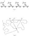
- Each riding vehicle 1 may either travel independently, or be connected in a line, and travel as a train, as shown in Figure 2 .
- the rail 2 either in a closed shape or in a linear shape, comprises a stimulating section 21 and a non-stimulating section 22, as shown in Figure 3 .
- the rail of the stimulating section 21 fluctuates significantly, which brings a great change of the velocity and the angular velocity to the riding vehicle 1.
- the rail of the non-stimulating section 22 does not have significant ups and downs, so that the riding vehicle 1 may travel in a constant velocity along the non-stimulating section 22.
- Rail switching devices 20 are mounted at a bifurcation and an intersection of the stimulating section 21 and the non-stimulating section 22.
- the rail switching device 20 includes a straight rail 23, a curve rail 24, a connector, a slide rail, and a driving and controlling device including a linear motor, and the rail switching device 20 can move laterally as a whole.
- the riding vehicle 1 can be directed to the stimulating section 21 via the rail switching device 20; and when the left end of the curve rail 24 is connected with the present rail, the riding vehicle 1 can be directed to the non-stimulating section via the rail switching device 20.
- the structures of the straight rail 23 and the curve rail 24 are similar to that of roller coaster rail, and the straight rail 23 and the curve rail 24 can move as a whole after being connected by the connectors.
- the straight rail 23, the curve rail 24 and the connectors are mounted on a slide rail, and a linear motor and its actuator are also mounted thereon for controlling the movement of the rail switching device 20.
- the distribution of riding vehicles in different experience lines of the experience system can also be controlled by controlling the position of the rail switching device 20.
- the rails of the experience system may also employ network lines formed by several stimulating sections and several non-stimulating sections, so as to provide tourists with rich multi-mode experience.
- Specific scenes including static scenes and dynamic scenes, are disposed on both sides of the rail 2 according to the originality of a theater.
- the static scenes are mainly indoor decorations, and the dynamic scenes may be generated by controllable and movable performance props.
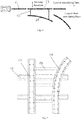
- a screen rail 4 is provided at the side of the rail 2.
- the screen rail 4 either in a closed shape or in a linear shape, is parallelly provided at the side of the rail 2.
- a screen synchronous moving mechanism 5 corresponding to the riding vehicle 1 and capable of traveling is provided on the screen rail 4.
- the screen synchronous moving mechanism 5 comprises a rotary support device 50 and a traveling device 51, and the traveling device 51 can travel synchronously with the riding vehicle 1 along the screen rail 4.
- the rotary support device 50 is installed with a screen 3 on the top thereof.
- the screen 3 is installed on the top of the rotary support device 50 and is capable of performing a 180° pitching motion via a pitch axis, such that the screen 3 can revert or maintain a certain posture. Meanwhile, the rotary support device 50 is installed on the traveling device 51 and is capable of performing a 360° rotation in a horizontal plane.
- the screens 3 include straight screens, arc screens, dome screens, irregular screens, fog screens, etc. Different types of screens are seamlessly combined with peripheral scenes for displaying specific movies. The tourists can watch movies or interact with elements in the movies.
- the screen synchronous moving mechanisms 5 can either stay still or travel around. When a riding vehicle travels to a position in front of the screen 3, it can either stop before the still screen 3 for watching videos or images, or travel synchronously with the screen 3, so as to provide the function that the tourists can watch videos or images during the traveling process.
- the screen rail 4, which is usually located in the same horizontal plane with the rail 2, can be designed into any shape. However, in the synchronous traveling sections, the screen rail 4 is required to be matching with the rail 2 along which the riding vehicle 1 is traveling.
- the screen traveling device 51 can travel along the screen rail 4 for supporting the screen 3 or adjusting the posture and position of the screen 3. When the riding vehicle 1 gets close to the screen 3, the screen traveling device 51 travels synchronously with the riding vehicle 1, and adjusts the position and posture of the screen 3, such that the screen 3 is always in front of the tourists during the traveling process to ensure the immersive feeling of the tourists.
- the riding vehicle 1 and the screen traveling device 51 of the screen 3 move apart after a period of time of synchronous traveling, and continue to travel along their own rails respectively, and the screen 3 may synchronously travel with another riding vehicle 1 at the next moment.
- the screen rail 4 may be a closed rail in any shape, or may be a non-closed rail.
- the screen may reciprocally moves along the non-closed rail, and the movement period of the screen is matching with the interval time between two adjacent riding vehicles.
- the screen 3 is capable of performing a 180° pitching motion via a pitch axis (i.e., reversal motion) to adapt its self with the synchronous traveling with the riding vehicle.
- riding vehicle 1 is in the form of two vehicles/line
- the moving screen 3 is also in the form of two screens/line.
- the present disclosure combines the experiences of a stimulating section and a non-stimulating section in one experience system, so as to satisfy different tourists' demands for different stimulating degrees, and thereby broaden the audience scope of the entertainment project.
- Network lines can be formed by the crossing and intersecting of different lines, which can significantly improve the space utilization of the entertainment facilities.
Description
- The present disclosure generally relates to amusement systems, and more particularly, to amusement-oriented multi-mode experience systems.
- Nowadays, the rails of entertainment projects, such as dark rides and roller coasters, are usually single-closed rails, and tourists can only have the experience in a single fixed line. Even for few dual-rail roller coasters, the two rails do not essentially cross or join and are actually two parallel rails, and the running parameters of riding vehicles traveling on these two rails, such as speed, acceleration, etc., are very close, and thus different types of experience cannot be provided. In addition, the dark rides or indoor roller coasters in prior art usually employ fixed scenes, i.e. screens are disposed on some scenes to display dynamic scenarios. The riding vehicle will stop for a period of time upon arriving to the screen and will continue to move after the tourists watch the movies. The above-mentioned ways of fixed screens require the riding vehicle to stop, which is difficult to meet the tourists' demands for watching movies during the traveling process.
-
US2009/084285A1 discloses an amusement-oriented multi-mode experience system with the features of the preamble ofclaim 1. - The present invention provides an amusement-oriented multi-mode experience system defined in
claim 1. Preferred embodiments are defined in the dependent claims. By using the experience system, tourists can watch movies and play games when the riding vehicle is moving. - An amusement-oriented multi-mode experience system of the present disclosure comprises a closed rail; a riding vehicle traveling along the rail. A screen rail is provided at the side of the rail. A screen synchronous moving mechanism corresponding to the riding vehicle and capable of traveling is provided on the screen rail. The screen synchronous moving mechanism comprises a rotary support device and a traveling device. The rotary support device is installed with a screen on the top thereof. The screen is installed on the top of the rotary support device and is capable of performing a 180° pitching motion via a pitch axis. The rotary support device is installed on the traveling device and is capable of performing a 360° rotation in a horizontal plane. The traveling device can travel along with the riding vehicle synchronously on the screen rail.
- The screen rail is closed and is in parallel with the rail.
- The screen rail is in a straight line shape and is disposed within the rail.
- The screen is a straight screen, an arc screen, a dome screen, an irregular screen or a fog screen.
- The riding vehicle comprises a wheel-type chassis adapted for traveling along the rail and a cabin mounted on the wheel-type chassis.
- The cabin is rotatably and retractably mounted on the wheel-type chassis via a support equipment.
- The rail comprises a stimulating section and a non-stimulating section.
- A rail switching device is mounted at a bifurcation and an intersection of the stimulating section and the non-stimulating section, the rail switching device includes a straight rail, a curve rail, a connector, a slide rail and a driving and controlling device, which can be assembled together into one piece being capable of lateral motion as a whole.
- A static scene and a dynamic scene are disposed on a side of the rail according to the originality of a theater.
- The experience system of the present disclosure incorporates different experience modes, and combines different experience lines and different movie-watching ways. The combination of different lines and different movie-watching ways can provide the tourists with a rich experience of multiple modes. In a single entertainment project, tourists can choose an exciting roller coaster line or a mild changing rail line, the tourists can watch movies on screens or interact when the riding vehicle stops or is traveling.
-
-
Figure 1 is a perspective schematic view of a single riding vehicle according to the present disclosure; -
Figure 2 is a structural schematic view of several riding vehicles jointed together according to the present disclosure; -
Figure 3 is a structural schematic view of a rail according to the present disclosure; -
Figure 4 is an operating principle schematic view of a rail switching device according to the present disclosure; -
Figure 5 is a structural schematic view of a rail switching device according to the present disclosure; -
Figure 6 is a structural schematic view of a screen synchronous moving mechanism according to the present disclosure, a front view and a side view of the screen synchronous moving mechanism are shown therein; -
Figure 7 is a schematic view of the distribution of the riding vehicles and screens according to the present disclosure; -
Figure 8 is a second schematic view of the distribution of the riding vehicles and screens according to the present invention. - Specific embodiments of the present disclosure will be described in details below by referring to the drawings.
- The amusement-oriented multi-mode experience system according to the present disclosure comprises a
riding vehicle 1, arail 2, ascreen 3, ascreen rail 4 and a screensynchronous moving mechanism 5, wherein, - The
riding vehicle 1 is used for carrying tourists, and may move on the fixedrail 2 by employing a wheel-type chassis 10, and eachriding vehicle 1 may carry several tourists. Atourist cabin 11 may be directly fixed on the wheel-type chassis 10, or may be connected to the wheel-type chassis 10 via a support equipment 12 (such as a multi-degree-of-freedom motion platform, an industrial robot arm, etc.) as shown inFigure 1 . Theriding vehicle 1 is either automatically driven by an on-board equipment, or driven by an external equipment, such as a friction wheel, a synchronous linear motor, etc. Since the connection between theriding vehicle 1 and therail 2 can be achieved by conventional technologies, it will not be described in details herein. - Each
riding vehicle 1 may either travel independently, or be connected in a line, and travel as a train, as shown inFigure 2 . - The
rail 2, either in a closed shape or in a linear shape, comprises a stimulating section 21 and anon-stimulating section 22, as shown inFigure 3 . The rail of the stimulating section 21 fluctuates significantly, which brings a great change of the velocity and the angular velocity to theriding vehicle 1. The rail of thenon-stimulating section 22 does not have significant ups and downs, so that theriding vehicle 1 may travel in a constant velocity along thenon-stimulating section 22.Rail switching devices 20 are mounted at a bifurcation and an intersection of the stimulating section 21 and thenon-stimulating section 22. As shown inFigures 4 and 5 , therail switching device 20 includes astraight rail 23, acurve rail 24, a connector, a slide rail, and a driving and controlling device including a linear motor, and therail switching device 20 can move laterally as a whole. When the left end of thestraight rail 23 is connected to the present rail, theriding vehicle 1 can be directed to the stimulating section 21 via therail switching device 20; and when the left end of thecurve rail 24 is connected with the present rail, theriding vehicle 1 can be directed to the non-stimulating section via therail switching device 20. The structures of thestraight rail 23 and thecurve rail 24 are similar to that of roller coaster rail, and thestraight rail 23 and thecurve rail 24 can move as a whole after being connected by the connectors. Thestraight rail 23, thecurve rail 24 and the connectors are mounted on a slide rail, and a linear motor and its actuator are also mounted thereon for controlling the movement of therail switching device 20. The distribution of riding vehicles in different experience lines of the experience system can also be controlled by controlling the position of therail switching device 20. The rails of the experience system may also employ network lines formed by several stimulating sections and several non-stimulating sections, so as to provide tourists with rich multi-mode experience. - Specific scenes, including static scenes and dynamic scenes, are disposed on both sides of the
rail 2 according to the originality of a theater. The static scenes are mainly indoor decorations, and the dynamic scenes may be generated by controllable and movable performance props. - As shown in
Figure 7 andFigure 8 , ascreen rail 4 is provided at the side of therail 2. Thescreen rail 4, either in a closed shape or in a linear shape, is parallelly provided at the side of therail 2. A screensynchronous moving mechanism 5 corresponding to theriding vehicle 1 and capable of traveling is provided on thescreen rail 4. As shown inFigure 6 , the screensynchronous moving mechanism 5 comprises arotary support device 50 and atraveling device 51, and thetraveling device 51 can travel synchronously with theriding vehicle 1 along thescreen rail 4. Therotary support device 50 is installed with ascreen 3 on the top thereof. Thescreen 3 is installed on the top of therotary support device 50 and is capable of performing a 180° pitching motion via a pitch axis, such that thescreen 3 can revert or maintain a certain posture. Meanwhile, therotary support device 50 is installed on the travelingdevice 51 and is capable of performing a 360° rotation in a horizontal plane. - The
screens 3 include straight screens, arc screens, dome screens, irregular screens, fog screens, etc. Different types of screens are seamlessly combined with peripheral scenes for displaying specific movies. The tourists can watch movies or interact with elements in the movies. - The screen synchronous moving
mechanisms 5 can either stay still or travel around. When a riding vehicle travels to a position in front of thescreen 3, it can either stop before the stillscreen 3 for watching videos or images, or travel synchronously with thescreen 3, so as to provide the function that the tourists can watch videos or images during the traveling process. - The
screen rail 4, which is usually located in the same horizontal plane with therail 2, can be designed into any shape. However, in the synchronous traveling sections, thescreen rail 4 is required to be matching with therail 2 along which theriding vehicle 1 is traveling. Thescreen traveling device 51 can travel along thescreen rail 4 for supporting thescreen 3 or adjusting the posture and position of thescreen 3. When the ridingvehicle 1 gets close to thescreen 3, thescreen traveling device 51 travels synchronously with the ridingvehicle 1, and adjusts the position and posture of thescreen 3, such that thescreen 3 is always in front of the tourists during the traveling process to ensure the immersive feeling of the tourists. The ridingvehicle 1 and thescreen traveling device 51 of thescreen 3 move apart after a period of time of synchronous traveling, and continue to travel along their own rails respectively, and thescreen 3 may synchronously travel with another ridingvehicle 1 at the next moment. Thescreen rail 4 may be a closed rail in any shape, or may be a non-closed rail. The screen may reciprocally moves along the non-closed rail, and the movement period of the screen is matching with the interval time between two adjacent riding vehicles. When anon-closed screen rail 4 is employed, thescreen 3 is capable of performing a 180° pitching motion via a pitch axis (i.e., reversal motion) to adapt its self with the synchronous traveling with the riding vehicle. When ridingvehicle 1 is in the form of two vehicles/line, the movingscreen 3 is also in the form of two screens/line. - In view of above, the present disclosure combines the experiences of a stimulating section and a non-stimulating section in one experience system, so as to satisfy different tourists' demands for different stimulating degrees, and thereby broaden the audience scope of the entertainment project. Network lines can be formed by the crossing and intersecting of different lines, which can significantly improve the space utilization of the entertainment facilities. By employing a moving screen synchronously traveling with the riding vehicle, the tourists may engage into the dynamic scenes during the traveling process, which substantially alters the previous experience mode of stopping for watching movies or interacting with scenes.
Claims (8)
- An amusement-oriented multi-mode experience system comprising a rail (2) and a riding vehicle (1) traveling along the rail (2),
a screen rail (4) is provided at a side of the rail (2), a screen synchronous moving mechanism (5) corresponding to the riding vehicle (1) and capable of traveling is provided on the screen rail (4), the screen synchronous moving mechanism (5) comprises a rotary support device (50) and a traveling device (51), the rotary support device (50) is installed with a screen (3) on the top thereof, the screen (3) is installed on the top of the rotary support device (50) and is capable of performing a 180° pitching motion via a pitch axis, and the rotary support device (50) is installed on the traveling device (51) and is capable of performing a 360° rotation in a horizontal plane, the traveling device (51) can travel along with the riding vehicle (1) synchronously on the screen rail (4),
characterized in that the
rail (2) is a closed rail, the screen rail (4) is in a straight line shape and is disposed within the rail (2) the screen synchronous moving mechanism (5) reciprocally moves along the screen rail (4), and the screen synchronous moving mechanism (5) is configured to move together with a first riding vehicle at a side of the screen rail (4) along a first direction, and then move together with a second riding vehicle at the other side of the screen rail (4) along a second direction contrary to the first direction after the screen (3) performing a 180° pitching motion via a pitch axis, wherein the second riding vehicle travels before the first riding vehicle. - The amusement-oriented multi-mode experience system of claim 1, wherein the screen rail (4) is closed and is in parallel with the closed rail (2).
- The amusement-oriented multi-mode experience system of claim 1, wherein the screen (3) is a straight screen, an arc screen, a dome screen, an irregular screen or a fog screen.
- The amusement-oriented multi-mode experience system of claim 1, wherein the riding vehicle (1) comprises a wheel-type chassis (10) adapted for traveling along the closed rail (2) and a tourist cabin (11) mounted on the wheel-type chassis (10).
- The amusement-oriented multi-mode experience system of claim 4, wherein the cabin (11) is rotatably and retractably mounted on the wheel-type chassis (10) via a support equipment.
- The amusement-oriented multi-mode experience system of claim 1, wherein the closed rail (2) comprises a stimulating section (21) and a non-stimulating section (22).
- The amusement-oriented multi-mode experience system of claim 6, wherein a rail switching device (20) is mounted at a bifurcation and an intersection of the stimulating section (21) and a non-stimulating section (22), and the rail switching device (20) comprises a straight rail (23), a curve rail (24), a connector, a slide rail, and a driving and controlling device, which can be assembled together into one piece being capable of lateral motion as a whole.
- The amusement-oriented multi-mode experience system of claim 1, wherein a static scene and a dynamic scene are disposed on a side of the closed rail (2) according to the originality of a theater.
Applications Claiming Priority (2)
| Application Number | Priority Date | Filing Date | Title |
|---|---|---|---|
| CN201510340589.4A CN104998415B (en) | 2015-06-18 | 2015-06-18 | Towards the multi-mode experiencing system of amusement |
| PCT/CN2015/084039 WO2016201755A1 (en) | 2015-06-18 | 2015-07-15 | Entertainment-oriented multi-mode experience system |
Publications (3)
| Publication Number | Publication Date |
|---|---|
| EP3311896A1 EP3311896A1 (en) | 2018-04-25 |
| EP3311896A4 EP3311896A4 (en) | 2019-01-09 |
| EP3311896B1 true EP3311896B1 (en) | 2020-08-26 |
Family
ID=54371436
Family Applications (1)
| Application Number | Title | Priority Date | Filing Date |
|---|---|---|---|
| EP15895328.1A Active EP3311896B1 (en) | 2015-06-18 | 2015-07-15 | Entertainment-oriented multi-mode experience system |
Country Status (5)
| Country | Link |
|---|---|
| US (1) | US10124265B2 (en) |
| EP (1) | EP3311896B1 (en) |
| CN (1) | CN104998415B (en) |
| ES (1) | ES2825705T3 (en) |
| WO (1) | WO2016201755A1 (en) |
Families Citing this family (8)
| Publication number | Priority date | Publication date | Assignee | Title |
|---|---|---|---|---|
| DE102016121799A1 (en) * | 2016-11-14 | 2018-05-17 | Mack Rides Gmbh & Co. Kg | Ride, especially roller coaster |
| CN107320969B (en) * | 2017-08-31 | 2019-09-20 | 大连万达集团股份有限公司 | The dark riding and carrying device of the innervation that can be rolled |
| DE102018209174A1 (en) * | 2018-06-08 | 2019-12-12 | Kuka Deutschland Gmbh | ride |
| US11338213B2 (en) * | 2018-11-12 | 2022-05-24 | Frank Heimes | Acceleration section for a water slide |
| CN109157850A (en) * | 2018-11-15 | 2019-01-08 | 中山市金马科技娱乐设备股份有限公司 | A kind of amusement facility with the mechanism that switches tracks |
| CN109173280A (en) * | 2018-11-15 | 2019-01-11 | 中山市金马科技娱乐设备股份有限公司 | A kind of amusement facility with cyclic track system |
| CN109692481B (en) * | 2018-11-21 | 2021-12-14 | 北京中冶设备研究设计总院有限公司 | Rolling type roller coaster device |
| DE202020101431U1 (en) * | 2020-03-16 | 2021-06-17 | Hereus Establishment | Amusement ride |
Family Cites Families (21)
| Publication number | Priority date | Publication date | Assignee | Title |
|---|---|---|---|---|
| JP3280051B2 (en) * | 1991-12-13 | 2002-04-30 | 株式会社トーゴ | Orbit traveling viewing device |
| JPH1015248A (en) * | 1996-07-04 | 1998-01-20 | Sega Enterp Ltd | Play facility and its elevator |
| JPH1115248A (en) | 1997-06-23 | 1999-01-22 | Fuji Xerox Co Ltd | Toner supply device |
| US7666192B2 (en) * | 2001-02-16 | 2010-02-23 | Kci Licensing, Inc. | Skin grafting devices and methods |
| EP2178610B1 (en) * | 2007-07-06 | 2012-09-05 | Vekoma Rides Engineering B.V. | Amusement ride installation |
| DE102007048012B4 (en) | 2007-09-27 | 2016-03-24 | Robocoaster Ltd. | ride |
| US9839856B2 (en) * | 2008-03-11 | 2017-12-12 | Disney Enterprises, Inc. | Method and system for providing interactivity based on sensor measurements |
| US8179337B2 (en) * | 2008-09-02 | 2012-05-15 | Disney Enterprises | Mobile projected sets |
| US7905790B2 (en) * | 2008-09-05 | 2011-03-15 | Disney Enterprises, Inc. | Theme park ride with ride-through screen system |
| US8021236B2 (en) * | 2009-03-30 | 2011-09-20 | Blammo, Llc | Amusement ride system and method |
| US8137205B2 (en) | 2009-12-04 | 2012-03-20 | Universal City Studios Llc | Motion-based attraction |
| US8727896B2 (en) * | 2012-03-14 | 2014-05-20 | Anton Frolov | Underground and underwater amusement attractions |
| CN202715234U (en) * | 2012-08-06 | 2013-02-06 | 深圳华侨城文化旅游科技有限公司 | Interactive rail car of amusement park |
| CA2907278C (en) * | 2012-10-26 | 2018-08-28 | Dynamic Structures, Ltd. | Flying theatre |
| CN103212205B (en) * | 2013-04-24 | 2016-08-03 | 江苏金刚文化科技集团股份有限公司 | A kind of motor-driven multiple degrees of freedom riding type large-scale recreation experience device |
| GB201320319D0 (en) | 2013-11-18 | 2014-01-01 | Robocoaster Ltd | Movable screen |
| US9278292B2 (en) * | 2014-06-10 | 2016-03-08 | Universal City Studios Llc | Moving show door |
| CN104225922B (en) | 2014-10-16 | 2016-03-30 | 芜湖华强文化科技产业有限公司 | A kind of tunnel type amusement device for experiencing |
| CN204215700U (en) * | 2014-11-07 | 2015-03-18 | 上海杰成展览展示有限公司 | A kind of Novel movable screen apparatus |
| CN104537968B (en) * | 2014-12-31 | 2017-04-26 | 深圳市科瑞兹科技有限公司 | Electronic welcome board, electronic white board and electronic rostrum |
| CN204745632U (en) * | 2015-06-18 | 2015-11-11 | 万达文化旅游规划研究院有限公司 | Device is experienced to multi -mode towards amusement |
-
2015
- 2015-06-18 CN CN201510340589.4A patent/CN104998415B/en active Active
- 2015-07-15 ES ES15895328T patent/ES2825705T3/en active Active
- 2015-07-15 WO PCT/CN2015/084039 patent/WO2016201755A1/en active Application Filing
- 2015-07-15 EP EP15895328.1A patent/EP3311896B1/en active Active
- 2015-07-15 US US15/737,077 patent/US10124265B2/en active Active
Non-Patent Citations (1)
| Title |
|---|
| None * |
Also Published As
| Publication number | Publication date |
|---|---|
| US20180229129A1 (en) | 2018-08-16 |
| US10124265B2 (en) | 2018-11-13 |
| EP3311896A4 (en) | 2019-01-09 |
| WO2016201755A1 (en) | 2016-12-22 |
| EP3311896A1 (en) | 2018-04-25 |
| CN104998415A (en) | 2015-10-28 |
| ES2825705T3 (en) | 2021-05-17 |
| CN104998415B (en) | 2017-08-25 |
Similar Documents
| Publication | Publication Date | Title |
|---|---|---|
| EP3311896B1 (en) | Entertainment-oriented multi-mode experience system | |
| CN101277744B (en) | Amusement ride track with motion base | |
| EP3090789B1 (en) | Platform dynamic vehicle | |
| RU2633222C1 (en) | Moving demonstration door | |
| EP3356005B1 (en) | Amusement park ride tunnel | |
| EP3804827B1 (en) | Trackless vehicle and system for synchronous control of trackless vehicle | |
| EP3147012B1 (en) | Circulating dynamic vehicle viewing system | |
| WO2015071693A1 (en) | Movable screen | |
| EP1079906A1 (en) | Amusement ride vehicle | |
| CN108786122B (en) | Dark ride vehicle system | |
| EP2821116A1 (en) | Attraction for amusement rides based on motion simulation | |
| CN204745632U (en) | Device is experienced to multi -mode towards amusement | |
| JPH0683095U (en) | Entertainment vehicle | |
| CN116510321A (en) | Self-driven sliding rope mechanism |
Legal Events
| Date | Code | Title | Description |
|---|---|---|---|
| STAA | Information on the status of an ep patent application or granted ep patent |
Free format text: STATUS: THE INTERNATIONAL PUBLICATION HAS BEEN MADE |
|
| PUAI | Public reference made under article 153(3) epc to a published international application that has entered the european phase |
Free format text: ORIGINAL CODE: 0009012 |
|
| STAA | Information on the status of an ep patent application or granted ep patent |
Free format text: STATUS: REQUEST FOR EXAMINATION WAS MADE |
|
| 17P | Request for examination filed |
Effective date: 20171214 |
|
| AK | Designated contracting states |
Kind code of ref document: A1 Designated state(s): AL AT BE BG CH CY CZ DE DK EE ES FI FR GB GR HR HU IE IS IT LI LT LU LV MC MK MT NL NO PL PT RO RS SE SI SK SM TR |
|
| AX | Request for extension of the european patent |
Extension state: BA ME |
|
| DAV | Request for validation of the european patent (deleted) | ||
| DAX | Request for extension of the european patent (deleted) | ||
| A4 | Supplementary search report drawn up and despatched |
Effective date: 20181211 |
|
| RIC1 | Information provided on ipc code assigned before grant |
Ipc: A63G 31/02 20060101AFI20181205BHEP Ipc: A63G 25/00 20060101ALI20181205BHEP Ipc: A63G 21/04 20060101ALI20181205BHEP Ipc: A63G 21/06 20060101ALI20181205BHEP |
|
| GRAP | Despatch of communication of intention to grant a patent |
Free format text: ORIGINAL CODE: EPIDOSNIGR1 |
|
| STAA | Information on the status of an ep patent application or granted ep patent |
Free format text: STATUS: GRANT OF PATENT IS INTENDED |
|
| INTG | Intention to grant announced |
Effective date: 20200506 |
|
| GRAS | Grant fee paid |
Free format text: ORIGINAL CODE: EPIDOSNIGR3 |
|
| GRAA | (expected) grant |
Free format text: ORIGINAL CODE: 0009210 |
|
| STAA | Information on the status of an ep patent application or granted ep patent |
Free format text: STATUS: THE PATENT HAS BEEN GRANTED |
|
| AK | Designated contracting states |
Kind code of ref document: B1 Designated state(s): AL AT BE BG CH CY CZ DE DK EE ES FI FR GB GR HR HU IE IS IT LI LT LU LV MC MK MT NL NO PL PT RO RS SE SI SK SM TR |
|
| REG | Reference to a national code |
Ref country code: GB Ref legal event code: FG4D |
|
| REG | Reference to a national code |
Ref country code: CH Ref legal event code: EP |
|
| REG | Reference to a national code |
Ref country code: DE Ref legal event code: R096 Ref document number: 602015058195 Country of ref document: DE |
|
| REG | Reference to a national code |
Ref country code: AT Ref legal event code: REF Ref document number: 1305807 Country of ref document: AT Kind code of ref document: T Effective date: 20200915 |
|
| REG | Reference to a national code |
Ref country code: IE Ref legal event code: FG4D |
|
| REG | Reference to a national code |
Ref country code: LT Ref legal event code: MG4D |
|
| PG25 | Lapsed in a contracting state [announced via postgrant information from national office to epo] |
Ref country code: HR Free format text: LAPSE BECAUSE OF FAILURE TO SUBMIT A TRANSLATION OF THE DESCRIPTION OR TO PAY THE FEE WITHIN THE PRESCRIBED TIME-LIMIT Effective date: 20200826 Ref country code: SE Free format text: LAPSE BECAUSE OF FAILURE TO SUBMIT A TRANSLATION OF THE DESCRIPTION OR TO PAY THE FEE WITHIN THE PRESCRIBED TIME-LIMIT Effective date: 20200826 Ref country code: GR Free format text: LAPSE BECAUSE OF FAILURE TO SUBMIT A TRANSLATION OF THE DESCRIPTION OR TO PAY THE FEE WITHIN THE PRESCRIBED TIME-LIMIT Effective date: 20201127 Ref country code: NO Free format text: LAPSE BECAUSE OF FAILURE TO SUBMIT A TRANSLATION OF THE DESCRIPTION OR TO PAY THE FEE WITHIN THE PRESCRIBED TIME-LIMIT Effective date: 20201126 Ref country code: FI Free format text: LAPSE BECAUSE OF FAILURE TO SUBMIT A TRANSLATION OF THE DESCRIPTION OR TO PAY THE FEE WITHIN THE PRESCRIBED TIME-LIMIT Effective date: 20200826 Ref country code: PT Free format text: LAPSE BECAUSE OF FAILURE TO SUBMIT A TRANSLATION OF THE DESCRIPTION OR TO PAY THE FEE WITHIN THE PRESCRIBED TIME-LIMIT Effective date: 20201228 Ref country code: BG Free format text: LAPSE BECAUSE OF FAILURE TO SUBMIT A TRANSLATION OF THE DESCRIPTION OR TO PAY THE FEE WITHIN THE PRESCRIBED TIME-LIMIT Effective date: 20201126 Ref country code: LT Free format text: LAPSE BECAUSE OF FAILURE TO SUBMIT A TRANSLATION OF THE DESCRIPTION OR TO PAY THE FEE WITHIN THE PRESCRIBED TIME-LIMIT Effective date: 20200826 |
|
| REG | Reference to a national code |
Ref country code: NL Ref legal event code: MP Effective date: 20200826 |
|
| REG | Reference to a national code |
Ref country code: AT Ref legal event code: MK05 Ref document number: 1305807 Country of ref document: AT Kind code of ref document: T Effective date: 20200826 |
|
| PG25 | Lapsed in a contracting state [announced via postgrant information from national office to epo] |
Ref country code: PL Free format text: LAPSE BECAUSE OF FAILURE TO SUBMIT A TRANSLATION OF THE DESCRIPTION OR TO PAY THE FEE WITHIN THE PRESCRIBED TIME-LIMIT Effective date: 20200826 Ref country code: NL Free format text: LAPSE BECAUSE OF FAILURE TO SUBMIT A TRANSLATION OF THE DESCRIPTION OR TO PAY THE FEE WITHIN THE PRESCRIBED TIME-LIMIT Effective date: 20200826 Ref country code: LV Free format text: LAPSE BECAUSE OF FAILURE TO SUBMIT A TRANSLATION OF THE DESCRIPTION OR TO PAY THE FEE WITHIN THE PRESCRIBED TIME-LIMIT Effective date: 20200826 Ref country code: RS Free format text: LAPSE BECAUSE OF FAILURE TO SUBMIT A TRANSLATION OF THE DESCRIPTION OR TO PAY THE FEE WITHIN THE PRESCRIBED TIME-LIMIT Effective date: 20200826 Ref country code: IS Free format text: LAPSE BECAUSE OF FAILURE TO SUBMIT A TRANSLATION OF THE DESCRIPTION OR TO PAY THE FEE WITHIN THE PRESCRIBED TIME-LIMIT Effective date: 20201226 |
|
| PG25 | Lapsed in a contracting state [announced via postgrant information from national office to epo] |
Ref country code: EE Free format text: LAPSE BECAUSE OF FAILURE TO SUBMIT A TRANSLATION OF THE DESCRIPTION OR TO PAY THE FEE WITHIN THE PRESCRIBED TIME-LIMIT Effective date: 20200826 Ref country code: SM Free format text: LAPSE BECAUSE OF FAILURE TO SUBMIT A TRANSLATION OF THE DESCRIPTION OR TO PAY THE FEE WITHIN THE PRESCRIBED TIME-LIMIT Effective date: 20200826 Ref country code: RO Free format text: LAPSE BECAUSE OF FAILURE TO SUBMIT A TRANSLATION OF THE DESCRIPTION OR TO PAY THE FEE WITHIN THE PRESCRIBED TIME-LIMIT Effective date: 20200826 Ref country code: DK Free format text: LAPSE BECAUSE OF FAILURE TO SUBMIT A TRANSLATION OF THE DESCRIPTION OR TO PAY THE FEE WITHIN THE PRESCRIBED TIME-LIMIT Effective date: 20200826 Ref country code: CZ Free format text: LAPSE BECAUSE OF FAILURE TO SUBMIT A TRANSLATION OF THE DESCRIPTION OR TO PAY THE FEE WITHIN THE PRESCRIBED TIME-LIMIT Effective date: 20200826 |
|
| REG | Reference to a national code |
Ref country code: ES Ref legal event code: FG2A Ref document number: 2825705 Country of ref document: ES Kind code of ref document: T3 Effective date: 20210517 |
|
| REG | Reference to a national code |
Ref country code: DE Ref legal event code: R097 Ref document number: 602015058195 Country of ref document: DE |
|
| PG25 | Lapsed in a contracting state [announced via postgrant information from national office to epo] |
Ref country code: AT Free format text: LAPSE BECAUSE OF FAILURE TO SUBMIT A TRANSLATION OF THE DESCRIPTION OR TO PAY THE FEE WITHIN THE PRESCRIBED TIME-LIMIT Effective date: 20200826 Ref country code: AL Free format text: LAPSE BECAUSE OF FAILURE TO SUBMIT A TRANSLATION OF THE DESCRIPTION OR TO PAY THE FEE WITHIN THE PRESCRIBED TIME-LIMIT Effective date: 20200826 |
|
| PG25 | Lapsed in a contracting state [announced via postgrant information from national office to epo] |
Ref country code: SK Free format text: LAPSE BECAUSE OF FAILURE TO SUBMIT A TRANSLATION OF THE DESCRIPTION OR TO PAY THE FEE WITHIN THE PRESCRIBED TIME-LIMIT Effective date: 20200826 |
|
| PLBE | No opposition filed within time limit |
Free format text: ORIGINAL CODE: 0009261 |
|
| STAA | Information on the status of an ep patent application or granted ep patent |
Free format text: STATUS: NO OPPOSITION FILED WITHIN TIME LIMIT |
|
| PG25 | Lapsed in a contracting state [announced via postgrant information from national office to epo] |
Ref country code: IT Free format text: LAPSE BECAUSE OF FAILURE TO SUBMIT A TRANSLATION OF THE DESCRIPTION OR TO PAY THE FEE WITHIN THE PRESCRIBED TIME-LIMIT Effective date: 20200826 |
|
| 26N | No opposition filed |
Effective date: 20210527 |
|
| PG25 | Lapsed in a contracting state [announced via postgrant information from national office to epo] |
Ref country code: SI Free format text: LAPSE BECAUSE OF FAILURE TO SUBMIT A TRANSLATION OF THE DESCRIPTION OR TO PAY THE FEE WITHIN THE PRESCRIBED TIME-LIMIT Effective date: 20200826 |
|
| REG | Reference to a national code |
Ref country code: DE Ref legal event code: R119 Ref document number: 602015058195 Country of ref document: DE |
|
| REG | Reference to a national code |
Ref country code: CH Ref legal event code: PL |
|
| PG25 | Lapsed in a contracting state [announced via postgrant information from national office to epo] |
Ref country code: MC Free format text: LAPSE BECAUSE OF FAILURE TO SUBMIT A TRANSLATION OF THE DESCRIPTION OR TO PAY THE FEE WITHIN THE PRESCRIBED TIME-LIMIT Effective date: 20200826 |
|
| REG | Reference to a national code |
Ref country code: BE Ref legal event code: MM Effective date: 20210731 |
|
| PG25 | Lapsed in a contracting state [announced via postgrant information from national office to epo] |
Ref country code: LI Free format text: LAPSE BECAUSE OF NON-PAYMENT OF DUE FEES Effective date: 20210731 Ref country code: DE Free format text: LAPSE BECAUSE OF NON-PAYMENT OF DUE FEES Effective date: 20220201 Ref country code: CH Free format text: LAPSE BECAUSE OF NON-PAYMENT OF DUE FEES Effective date: 20210731 |
|
| PG25 | Lapsed in a contracting state [announced via postgrant information from national office to epo] |
Ref country code: LU Free format text: LAPSE BECAUSE OF NON-PAYMENT OF DUE FEES Effective date: 20210715 |
|
| PG25 | Lapsed in a contracting state [announced via postgrant information from national office to epo] |
Ref country code: IE Free format text: LAPSE BECAUSE OF NON-PAYMENT OF DUE FEES Effective date: 20210715 Ref country code: BE Free format text: LAPSE BECAUSE OF NON-PAYMENT OF DUE FEES Effective date: 20210731 |
|
| PG25 | Lapsed in a contracting state [announced via postgrant information from national office to epo] |
Ref country code: HU Free format text: LAPSE BECAUSE OF FAILURE TO SUBMIT A TRANSLATION OF THE DESCRIPTION OR TO PAY THE FEE WITHIN THE PRESCRIBED TIME-LIMIT; INVALID AB INITIO Effective date: 20150715 |
|
| PG25 | Lapsed in a contracting state [announced via postgrant information from national office to epo] |
Ref country code: CY Free format text: LAPSE BECAUSE OF FAILURE TO SUBMIT A TRANSLATION OF THE DESCRIPTION OR TO PAY THE FEE WITHIN THE PRESCRIBED TIME-LIMIT Effective date: 20200826 |
|
| PGFP | Annual fee paid to national office [announced via postgrant information from national office to epo] |
Ref country code: FR Payment date: 20230622 Year of fee payment: 9 |
|
| PGFP | Annual fee paid to national office [announced via postgrant information from national office to epo] |
Ref country code: GB Payment date: 20230615 Year of fee payment: 9 Ref country code: ES Payment date: 20230809 Year of fee payment: 9 |
|
| PG25 | Lapsed in a contracting state [announced via postgrant information from national office to epo] |
Ref country code: MK Free format text: LAPSE BECAUSE OF FAILURE TO SUBMIT A TRANSLATION OF THE DESCRIPTION OR TO PAY THE FEE WITHIN THE PRESCRIBED TIME-LIMIT Effective date: 20200826 |