EP3311728A1 - Insertion apparatus and insertion device - Google Patents
Insertion apparatus and insertion device Download PDFInfo
- Publication number
- EP3311728A1 EP3311728A1 EP16811278.7A EP16811278A EP3311728A1 EP 3311728 A1 EP3311728 A1 EP 3311728A1 EP 16811278 A EP16811278 A EP 16811278A EP 3311728 A1 EP3311728 A1 EP 3311728A1
- Authority
- EP
- European Patent Office
- Prior art keywords
- index
- dimension
- assistance tool
- insertion section
- reference position
- Prior art date
- Legal status (The legal status is an assumption and is not a legal conclusion. Google has not performed a legal analysis and makes no representation as to the accuracy of the status listed.)
- Withdrawn
Links
- 238000003780 insertion Methods 0.000 title claims abstract description 104
- 230000037431 insertion Effects 0.000 title claims abstract description 104
- 238000012986 modification Methods 0.000 description 22
- 230000004048 modification Effects 0.000 description 22
- 238000010586 diagram Methods 0.000 description 8
- 230000002093 peripheral effect Effects 0.000 description 7
- 238000003384 imaging method Methods 0.000 description 4
- 210000003238 esophagus Anatomy 0.000 description 2
- 210000002784 stomach Anatomy 0.000 description 2
- 230000000694 effects Effects 0.000 description 1
- 238000005286 illumination Methods 0.000 description 1
- 210000000936 intestine Anatomy 0.000 description 1
- 238000000034 method Methods 0.000 description 1
Images

Classifications
-
- A—HUMAN NECESSITIES
- A61—MEDICAL OR VETERINARY SCIENCE; HYGIENE
- A61B—DIAGNOSIS; SURGERY; IDENTIFICATION
- A61B1/00—Instruments for performing medical examinations of the interior of cavities or tubes of the body by visual or photographical inspection, e.g. endoscopes; Illuminating arrangements therefor
- A61B1/00147—Holding or positioning arrangements
- A61B1/00148—Holding or positioning arrangements using anchoring means
-
- A—HUMAN NECESSITIES
- A61—MEDICAL OR VETERINARY SCIENCE; HYGIENE
- A61B—DIAGNOSIS; SURGERY; IDENTIFICATION
- A61B1/00—Instruments for performing medical examinations of the interior of cavities or tubes of the body by visual or photographical inspection, e.g. endoscopes; Illuminating arrangements therefor
- A61B1/00002—Operational features of endoscopes
- A61B1/00011—Operational features of endoscopes characterised by signal transmission
- A61B1/00018—Operational features of endoscopes characterised by signal transmission using electrical cables
-
- A—HUMAN NECESSITIES
- A61—MEDICAL OR VETERINARY SCIENCE; HYGIENE
- A61B—DIAGNOSIS; SURGERY; IDENTIFICATION
- A61B1/00—Instruments for performing medical examinations of the interior of cavities or tubes of the body by visual or photographical inspection, e.g. endoscopes; Illuminating arrangements therefor
- A61B1/00002—Operational features of endoscopes
- A61B1/00043—Operational features of endoscopes provided with output arrangements
- A61B1/00045—Display arrangement
-
- A—HUMAN NECESSITIES
- A61—MEDICAL OR VETERINARY SCIENCE; HYGIENE
- A61B—DIAGNOSIS; SURGERY; IDENTIFICATION
- A61B1/00—Instruments for performing medical examinations of the interior of cavities or tubes of the body by visual or photographical inspection, e.g. endoscopes; Illuminating arrangements therefor
- A61B1/00064—Constructional details of the endoscope body
- A61B1/00071—Insertion part of the endoscope body
-
- A—HUMAN NECESSITIES
- A61—MEDICAL OR VETERINARY SCIENCE; HYGIENE
- A61B—DIAGNOSIS; SURGERY; IDENTIFICATION
- A61B1/00—Instruments for performing medical examinations of the interior of cavities or tubes of the body by visual or photographical inspection, e.g. endoscopes; Illuminating arrangements therefor
- A61B1/00064—Constructional details of the endoscope body
- A61B1/00071—Insertion part of the endoscope body
- A61B1/0008—Insertion part of the endoscope body characterised by distal tip features
- A61B1/00097—Sensors
-
- A—HUMAN NECESSITIES
- A61—MEDICAL OR VETERINARY SCIENCE; HYGIENE
- A61B—DIAGNOSIS; SURGERY; IDENTIFICATION
- A61B1/00—Instruments for performing medical examinations of the interior of cavities or tubes of the body by visual or photographical inspection, e.g. endoscopes; Illuminating arrangements therefor
- A61B1/00131—Accessories for endoscopes
-
- A—HUMAN NECESSITIES
- A61—MEDICAL OR VETERINARY SCIENCE; HYGIENE
- A61B—DIAGNOSIS; SURGERY; IDENTIFICATION
- A61B1/00—Instruments for performing medical examinations of the interior of cavities or tubes of the body by visual or photographical inspection, e.g. endoscopes; Illuminating arrangements therefor
- A61B1/00131—Accessories for endoscopes
- A61B1/00135—Oversleeves mounted on the endoscope prior to insertion
-
- A—HUMAN NECESSITIES
- A61—MEDICAL OR VETERINARY SCIENCE; HYGIENE
- A61B—DIAGNOSIS; SURGERY; IDENTIFICATION
- A61B1/00—Instruments for performing medical examinations of the interior of cavities or tubes of the body by visual or photographical inspection, e.g. endoscopes; Illuminating arrangements therefor
- A61B1/00147—Holding or positioning arrangements
- A61B1/0016—Holding or positioning arrangements using motor drive units
-
- A—HUMAN NECESSITIES
- A61—MEDICAL OR VETERINARY SCIENCE; HYGIENE
- A61B—DIAGNOSIS; SURGERY; IDENTIFICATION
- A61B1/00—Instruments for performing medical examinations of the interior of cavities or tubes of the body by visual or photographical inspection, e.g. endoscopes; Illuminating arrangements therefor
- A61B1/04—Instruments for performing medical examinations of the interior of cavities or tubes of the body by visual or photographical inspection, e.g. endoscopes; Illuminating arrangements therefor combined with photographic or television appliances
- A61B1/05—Instruments for performing medical examinations of the interior of cavities or tubes of the body by visual or photographical inspection, e.g. endoscopes; Illuminating arrangements therefor combined with photographic or television appliances characterised by the image sensor, e.g. camera, being in the distal end portion
-
- A—HUMAN NECESSITIES
- A61—MEDICAL OR VETERINARY SCIENCE; HYGIENE
- A61B—DIAGNOSIS; SURGERY; IDENTIFICATION
- A61B1/00—Instruments for performing medical examinations of the interior of cavities or tubes of the body by visual or photographical inspection, e.g. endoscopes; Illuminating arrangements therefor
- A61B1/012—Instruments for performing medical examinations of the interior of cavities or tubes of the body by visual or photographical inspection, e.g. endoscopes; Illuminating arrangements therefor characterised by internal passages or accessories therefor
- A61B1/018—Instruments for performing medical examinations of the interior of cavities or tubes of the body by visual or photographical inspection, e.g. endoscopes; Illuminating arrangements therefor characterised by internal passages or accessories therefor for receiving instruments
-
- A—HUMAN NECESSITIES
- A61—MEDICAL OR VETERINARY SCIENCE; HYGIENE
- A61B—DIAGNOSIS; SURGERY; IDENTIFICATION
- A61B17/00—Surgical instruments, devices or methods
- A61B17/00234—Surgical instruments, devices or methods for minimally invasive surgery
- A61B2017/00292—Surgical instruments, devices or methods for minimally invasive surgery mounted on or guided by flexible, e.g. catheter-like, means
- A61B2017/00296—Surgical instruments, devices or methods for minimally invasive surgery mounted on or guided by flexible, e.g. catheter-like, means mounted on an endoscope
-
- A—HUMAN NECESSITIES
- A61—MEDICAL OR VETERINARY SCIENCE; HYGIENE
- A61B—DIAGNOSIS; SURGERY; IDENTIFICATION
- A61B90/00—Instruments, implements or accessories specially adapted for surgery or diagnosis and not covered by any of the groups A61B1/00 - A61B50/00, e.g. for luxation treatment or for protecting wound edges
- A61B90/06—Measuring instruments not otherwise provided for
- A61B2090/061—Measuring instruments not otherwise provided for for measuring dimensions, e.g. length
-
- A—HUMAN NECESSITIES
- A61—MEDICAL OR VETERINARY SCIENCE; HYGIENE
- A61B—DIAGNOSIS; SURGERY; IDENTIFICATION
- A61B90/00—Instruments, implements or accessories specially adapted for surgery or diagnosis and not covered by any of the groups A61B1/00 - A61B50/00, e.g. for luxation treatment or for protecting wound edges
- A61B90/08—Accessories or related features not otherwise provided for
- A61B2090/0807—Indication means
- A61B2090/0811—Indication means for the position of a particular part of an instrument with respect to the rest of the instrument, e.g. position of the anvil of a stapling instrument
Definitions
- the present invention relates to an insertion instrument in which an assistance tool attaching portion for attaching an assistance tool is provided in an insertion section, and an insertion device including the insertion instrument and the assistance tool.
- an insertion section and an assistance tool attached to the assistance tool attaching portion are inserted into the lumen from an insertion opening (i.e., the mouth).
- the observation of the inside of the lumen may be performed while the overall length of the assistance tool in the direction along the longitudinal axis is located inside of the lumen.
- the assistance tool since the assistance tool does not project outside of the patient's body from the insertion opening of the lumen, it is difficult for a surgeon to ascertain the position of the assistance tool which is located inside of the lumen.
- the present invention was designed to address the above problem, and an objective of the present invention is to provide an insertion instrument and an insertion device that allow a surgeon to easily ascertain the position of the assistance tool inside the lumen.
- FIG. 1 shows an endoscope device 1 which is an insertion device according to the present embodiment.
- the endoscope device 1 includes an endoscope 2 which serves as an insertion instrument, and a spiral unit 10 which serves as an assistance tool.
- the endoscope 2 includes an insertion section 3, and the insertion section 3 has a longitudinal axis C.
- the direction along the longitudinal direction is defined as a longitudinal axis C.
- One side on the longitudinal axis C is defined as a distal side (indicated by arrow C1 in FIG. 1 ), and a side opposite to the distal side is defined as a proximal side (indicated by arrow C2 in FIG. 1 ).
- An imaging element such as a CCD is provided inside of the distal portion of the insertion section 3, and the imaging element captures an image of a subject through an observation window (not shown in the drawings) provided on the outer surface of the distal portion of the insertion portion 3. Furthermore, an image signal is transmitted to the image processing device via an imaging cable (not shown in the drawings) extending through the inside of the insertion section 3, the inside of the operation section 5, and the inside of the universal cord 6, and an imaging process is performed by the image processing device. Thus, an image of a subject is generated by the image processing device, and the generated image of the subject is displayed on the display device.
- Light emitted from the light source device is guided through a light guide extending through the inside of the insertion section 3, the inside of the operation section 5, and the inside of the universal cord 6.
- the guided light is emitted on the subject through an illumination window (not shown in the drawings) which is provided on the outer surface of the distal portion of the insertion portion 3.
- FIG. 2 shows the configuration of the proximal portion of the insertion section 3 (the range II in FIG. 1 ).
- Each of the dimension indices Ai is an index indicating a dimension from the distal end of the insertion section 3.
- the dimension index A7 is an index indicating a position that is 70 cm (700 mm) from the distal end of the insertion section 3 toward the proximal side.
- the dimension indices Ai are spaced from each other in the direction along the longitudinal axis C (the longitudinal direction); in the present embodiment, the dimension indices Ai are spaced every 10 cm (100 mm).
- a position index 20 is provided on the outer surface of the proximal portion of the insertion section 3.
- the position index 20 is located at a reference position that is spaced from the proximal end of the spiral unit (an assistance tool) 10 at a predetermined dimension D0 to the proximal side, with the spiral unit 10 being attached to the assistance tool attaching portion (7, 8), and the position index 20 becomes an index indicating that the position is a reference position.
- a predetermined dimension DO is 40 cm (400 mm)
- a position that is 40 cm (400 mm) from the proximal end of the spiral unit 10 which is attached to the assistance tool attaching portion (7, 8) toward the proximal side is defined as a reference position.
- the function and advantageous effects of the endoscope (an insertion instrument) 2 and the endoscope device (an insertion device) 1 according to the present embodiment are explained.
- the spiral unit (an assistance tool) 10 is attached to the assistance tool attaching portion (7, 8) of the insertion section 3, and the insertion section 3 and the spiral unit 10 are inserted into the lumen.
- the insertion section 3 and the spiral unit 10 are inserted from an insertion opening, such as the mouth, into the lumen.
- the spiral unit 10 rotates about the longitudinal axis C.
- the propulsion force toward the distal side or the proximal side acts on the insertion section 3 and the spiral unit 10.
- the movability of the insertion section 3 in the lumen is improved by the propulsion force.
- the indicating state of the position index 20 is not limited to that in the first embodiment.
- a position index 20 is formed only by an emphasis line 22 adjacently provided on the proximal side of the dimension index A8.
- an emphasis pattern 23 is adjacently provided on the proximal side of the dimension index A8, and a position index 20 is formed only by the emphasis pattern 23.
- an emphasis dashed line 25 is adjacently provided on the proximal side of the dimension index A8, and a position index 20 is formed only by the emphasis dashed line 25.
- an emphasis pattern 26 is adjacently provided on the distal side of the dimension index A8, an emphasis pattern 27 is adjacently provided on the proximal side of the dimension index A8, and the dimension index A8 is located between the emphasis pattern 26 and the emphasis pattern 27 in the direction along the longitudinal axis C.
- a position index 20 is formed by the emphasis pattern 26 and the emphasis pattern 27.
- the dimension index A8, which is one of the dimension indices Ai, and the position index 20 are located at the reference position that is spaced from the proximal end of the spiral unit 10 attached to the assistance tool attaching portion (7, 8) at a predetermined dimension D0 to the proximal side.
- the dimension index A8 may serve also as the position index 20 indicating the reference position, by forming only the scale line S8 of the dimension index A8 to be thick.
- the dimension index A8 located at the reference position is indicated in a dashed line, whereas the other dimension indices (Ai other than A8) are indicated in solid lines.
- the dimension index A8 may serve also as the position index 20 indicating the reference position.
- a position index (20) may be formed by a dimension index (for example, A8) located at a reference position by indicating the dimension index (for example, A8) located at the reference position in a color different from the color of the other dimension indices (for example, Ai other than A8).
- the position that is 85 cm (850 mm) from the distal end of the insertion section 3 to the proximal side corresponds to the reference position that is spaced from the proximal end of the spiral unit 10 at a predetermined dimension D0 to the proximal side.
- the insertion instrument (2) includes the insertion section (3) extending from the proximal side to the distal side along the longitudinal axis, and the assistance tool attaching portion (7, 8) to which the assistance tool (10) is attached is provided in the insertion section (3).
- the dimension indices (Ai) are provided on the outer surface of the insertion section (3) as indices indicating dimensions from the distal end of the insertion section (3).
Landscapes
- Health & Medical Sciences (AREA)
- Life Sciences & Earth Sciences (AREA)
- Surgery (AREA)
- Biomedical Technology (AREA)
- Medical Informatics (AREA)
- Optics & Photonics (AREA)
- Pathology (AREA)
- Radiology & Medical Imaging (AREA)
- Biophysics (AREA)
- Engineering & Computer Science (AREA)
- Physics & Mathematics (AREA)
- Heart & Thoracic Surgery (AREA)
- Nuclear Medicine, Radiotherapy & Molecular Imaging (AREA)
- Molecular Biology (AREA)
- Animal Behavior & Ethology (AREA)
- General Health & Medical Sciences (AREA)
- Public Health (AREA)
- Veterinary Medicine (AREA)
- Instruments For Viewing The Inside Of Hollow Bodies (AREA)
- Endoscopes (AREA)
Abstract
Description
- The present invention relates to an insertion instrument in which an assistance tool attaching portion for attaching an assistance tool is provided in an insertion section, and an insertion device including the insertion instrument and the assistance tool.
- International Publication No.
2013/038720 discloses an endoscope device including an insertion section extending along a longitudinal axis, and an assistance tool (a spiral unit) which is attached to an assistance tool attaching portion provided in the insertion section. In the endoscope device, the assistance tool rotates about the longitudinal axis when a driving force is transmitted to the assistance tool with the assistance tool being attached to the assistance tool attaching portion. The rotation of the assistance tool while being pressed toward the inner peripheral side causes a propulsion force toward the distal side or the proximal side to act on the insertion section and the assistance tool. - In the insertion device disclosed in, for example, International Publication No.
2013/038720 , when the inside of a lumen is observed using the insertion device, an insertion section and an assistance tool attached to the assistance tool attaching portion are inserted into the lumen from an insertion opening (i.e., the mouth). The observation of the inside of the lumen may be performed while the overall length of the assistance tool in the direction along the longitudinal axis is located inside of the lumen. In this case, since the assistance tool does not project outside of the patient's body from the insertion opening of the lumen, it is difficult for a surgeon to ascertain the position of the assistance tool which is located inside of the lumen. - The present invention was designed to address the above problem, and an objective of the present invention is to provide an insertion instrument and an insertion device that allow a surgeon to easily ascertain the position of the assistance tool inside the lumen.
- To solve the above mentioned problems, according to one aspect of the invention, an insertion instrument including: an insertion section including an assistance tool attaching portion to which an assistance tool is attached, the insertion section extending from a proximal side to a distal side along a longitudinal axis; a dimension index which is provided on an outer surface of the insertion section, and which indicates a dimension from a distal end of the insertion section; and a position index provided at a reference position, which is spaced from a proximal end of the assistance tool attached to the assistance tool attaching portion at a predetermined dimension to the proximal side, on the outer surface of the insertion section, the position index being an index indicating a position is the reference position.
-
-
FIG. 1 is a schematic diagram of an endoscope device according to a first embodiment, -
FIG. 2 is a schematic diagram of a proximal portion of an insertion section according to the first embodiment, -
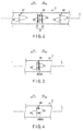
FIG. 3 is a schematic diagram of a dimension index and a position index according to a first modification, -
FIG. 4 is a schematic diagram of a dimension index and a position index according to a second modification, -
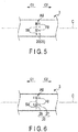
FIG. 5 is a schematic diagram of a dimension index and a position index according to a third modification, -
FIG. 6 is a schematic diagram of a dimension index and a position index according to a fourth modification, -
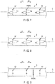
FIG. 7 is a schematic diagram of a proximal portion of an insertion section according to a fifth modification, -
FIG. 8 is a schematic view of a proximal portion of an insertion section according to a sixth modification, and -
FIG. 9 is a schematic diagram of a proximal portion of an insertion section according to a seventh modification. Description of Embodiments - The first embodiment of the present invention will be explained with reference to
FIG. 1 andFIG. 2 .FIG. 1 shows anendoscope device 1 which is an insertion device according to the present embodiment. - As shown in
FIG. 1 , theendoscope device 1 includes an endoscope 2 which serves as an insertion instrument, and aspiral unit 10 which serves as an assistance tool. The endoscope 2 includes aninsertion section 3, and theinsertion section 3 has a longitudinal axis C. Herein, the direction along the longitudinal direction is defined as a longitudinal axis C. One side on the longitudinal axis C is defined as a distal side (indicated by arrow C1 inFIG. 1 ), and a side opposite to the distal side is defined as a proximal side (indicated by arrow C2 inFIG. 1 ). Theinsertion section 3 extends from the proximal side toward the distal side along the longitudinal axis C, and in the endoscope 2, anoperation section 5 is provided on the proximal side with respect to theinsertion portion 3. The endoscope 2 includes a universal cord 6 one end of which is connected to theoperation section 5. The endoscope 2 is connected, via the universal cord 6, to a peripheral device unit that includes an image processing device (not shown in the drawings), a light source device (not shown in the drawings), a drive control device (not shown in the drawings), an operation input device (not shown in the drawings) such as a foot switch etc., and a display device (not shown in the drawings) such as a monitor, etc. - An imaging element (not shown in the drawings) such as a CCD is provided inside of the distal portion of the
insertion section 3, and the imaging element captures an image of a subject through an observation window (not shown in the drawings) provided on the outer surface of the distal portion of theinsertion portion 3. Furthermore, an image signal is transmitted to the image processing device via an imaging cable (not shown in the drawings) extending through the inside of theinsertion section 3, the inside of theoperation section 5, and the inside of the universal cord 6, and an imaging process is performed by the image processing device. Thus, an image of a subject is generated by the image processing device, and the generated image of the subject is displayed on the display device. Light emitted from the light source device is guided through a light guide extending through the inside of theinsertion section 3, the inside of theoperation section 5, and the inside of the universal cord 6. The guided light is emitted on the subject through an illumination window (not shown in the drawings) which is provided on the outer surface of the distal portion of theinsertion portion 3. - The
insertion section 3 includes abase portion 7, and arotation body 8 that is rotatably attached to thebase portion 7 in such a manner that therotation body 8 rotates about the longitudinal axis C with respect to thebase portion 7. Thebase portion 7 and therotation body 8 constitute the assistance tool attaching portion to which a spiral unit (an assistance tool) 10 is detachably attached. When thespiral unit 10 is attached to theinsertion section 3, theinsertion section 3 is inserted through thespiral unit 10, and the outer peripheral side of thebase portion 7 and therotation body 8 are covered with the proximal portion of thespiral unit 10. Thespiral unit 10 includes a cylindrical-shaped tubemain body 11 extending along the longitudinal axis C, and aspiral fin 12 projecting on the outer peripheral surface of the tubemain body 11 toward the outer peripheral side. Thespiral fin 12 spirally extends around the longitudinal axis C. - A
motor casing 15 is attached to theoperation section 5, and an electric motor (not shown in the drawings), which is a drive source, is provided inside themotor casing 15. By performing an operation input with the operation input device (not shown in the drawings), electric power is supplied to the electric motor from the drive control device through electric lines (not shown in the drawings) extending through the inside of theoperation section 5 and the inside of the universal cord 6, and the electric motor is driven. When the electric motor is driven, driving force is transmitted to a driving shaft (not shown in the drawings) extending between themotor casing 15 and thebase portion 7 inside of theinsertion portion 3, and the driving shaft rotates. Thus, the driving force is transmitted to therotation body 8, and therotation body 8 rotates about the longitudinal axis C with respect to thebase portion 7. When therotation body 8 rotates with thespiral unit 10 being attached to the assistance tool attaching portion (7, 8) of theinsertion section 3, the spiral unit (an assistance tool) 10 rotates about the longitudinal axis C with therotation body 8. In the present embodiment, a propulsion force in the distal side or the proximal side acts on theinsertion section 3 and thespiral unit 10 when thespiral unit 10 rotates with pressing pressure acting on thespiral fin 12 toward the inner peripheral side. -
FIG. 2 shows the configuration of the proximal portion of the insertion section 3 (the range II inFIG. 1 ). As shown inFIG. 2 , a plurality of dimension indices Ai (i = 1, 2, ...) are provided on the outer surface of theinsertion section 3. Each of the dimension indices Ai is an index indicating a dimension from the distal end of theinsertion section 3. For example, the dimension index A7 is an index indicating a position that is 70 cm (700 mm) from the distal end of theinsertion section 3 toward the proximal side. The dimension indices Ai are spaced from each other in the direction along the longitudinal axis C (the longitudinal direction); in the present embodiment, the dimension indices Ai are spaced every 10 cm (100 mm). Accordingly, each of the dimension indices Ai is placed at aposition 10 × i cm (i = 1, 2, ...) from the distal end of theinsertion section 3 to the proximal side. Each of the dimension indices Ai consists of a value Fi (i = 1, 2, ...), and a scale line Si (i = 1, 2, ...) that is a first line. In one example, when thespiral unit 10 is attached to the assistance tool attaching portion (7, 8), the distal end of thespiral unit 10 is located at a position that is 20 cm from the distal end of theinsertion section 3 toward the proximal side, and the proximal end of thespiral unit 10 is located at a position that is 40 cm from the distal end of theinsertion section 3 to the proximal side. In this case, thespiral unit 10 extends within the range where the dimension from the distal end of theinsertion section 3 to the proximal side falls under the range between 20 cm and 40 cm. - A
position index 20 is provided on the outer surface of the proximal portion of theinsertion section 3. Theposition index 20 is located at a reference position that is spaced from the proximal end of the spiral unit (an assistance tool) 10 at a predetermined dimension D0 to the proximal side, with thespiral unit 10 being attached to the assistance tool attaching portion (7, 8), and theposition index 20 becomes an index indicating that the position is a reference position. In one example, a predetermined dimension DO is 40 cm (400 mm), and a position that is 40 cm (400 mm) from the proximal end of thespiral unit 10 which is attached to the assistance tool attaching portion (7, 8) toward the proximal side is defined as a reference position. Accordingly, theposition index 20 located at a reference position is separated from the range where the spiral unit (the assistance tool) 10 attached to the assistance tool attaching portion (7, 8) of theinsertion section 3 rotates (actuates), in the direction along the longitudinal axis C. In the present embodiment, theposition index 20 consists ofemphasis lines position index 20 may be formed in the same color as or in a different color from the dimension indices Ai. In the present embodiment, the emphasis lines (the second lines) 21 and 22 of theposition index 20 are formed thicker than the scale lines (the first lines) Si of the dimension indices Ai. Accordingly, the dimension of each of the emphasis lines (the second lines) 21 and 22 in the direction along the longitudinal axis C is larger than the dimension of each of the scale lines (the first lines) Si in the direction along the longitudinal axis C - Furthermore, in the present embodiment, the reference position (a position that is separated from the proximal end of the
spiral unit 10 at a predetermined dimension DO to the proximal side) matches the position that is 80 cm (800 mm) from the distal end of theinsertion section 3 on to proximal side. Thus, the dimension index A8, which is one of the plurality of dimension indices Ai, is located at the reference position. In the present embodiment, theposition index 20 is formed by placing theemphasis line 21 adjacently to the distal side of the dimension index A8 and theemphasis line 22 adjacently to the proximal side of the dimension index A8, and the dimension index A8 is located between the emphasis lines 21 and 22 in the longitudinal direction. - Next, the function and advantageous effects of the endoscope (an insertion instrument) 2 and the endoscope device (an insertion device) 1 according to the present embodiment are explained. When the inside of a lumen, such as an intestine lumen, etc. is observed using the
endoscope device 1, the spiral unit (an assistance tool) 10 is attached to the assistance tool attaching portion (7, 8) of theinsertion section 3, and theinsertion section 3 and thespiral unit 10 are inserted into the lumen. At this time, theinsertion section 3 and thespiral unit 10 are inserted from an insertion opening, such as the mouth, into the lumen. Then, an operation input is performed by the operation input device (not shown in the drawings) with thespiral unit 10 being located inside of the lumen, the electric motor (not shown in the drawings) is driven, and the driving force is transmitted to thespiral unit 10 as described above. Thus, thespiral unit 10 rotates about the longitudinal axis C. When thespiral unit 10 rotates with thespiral fin 12 being pressed toward the inner peripheral side by the lumen wall, the propulsion force toward the distal side or the proximal side (one side of the direction along the longitudinal axis C) acts on theinsertion section 3 and thespiral unit 10. The movability of theinsertion section 3 in the lumen is improved by the propulsion force. - In the present embodiment, the
position index 20 is provided at the reference position that is separated from the proximal end of the spiral unit (an assistance tool) 10 at a predetermined dimension DO to the proximal end, and the reference position is indicated by theposition index 20. Thus, during the observation using theendoscope device 1, the surgeon can ascertain the position of thespiral unit 10 based on theposition index 20. During the observation using theendoscope device 1, the overall length of thespiral unit 10 in the direction along the longitudinal axis C may be located inside of the lumen; even in this case, the surgeon can appropriately ascertain the position of thespiral unit 10 inside of the body lumen based on theposition index 20 located outside the body. - For example, the
insertion section 3 and the spiral unit 10 (the assistance tool) are inserted into the lumen from the mouth (an insertion opening) using theendoscope device 1 in which aposition index 20 is provided at a reference position that is 40 cm (a predetermined dimension D0) from the proximal end of thespiral unit 10 to the proximal side. Herein, the dimension in the lumen (the esophagus) from the mouth (the insertion opening) to the stomach is usually about 40 cm (400 mm), with slight differences among subjects. Accordingly, while theinsertion section 3 and the spiral unit (the assistance tool) 10 are moving to the distal side in the lumen, the surgeon appropriately ascertains that the proximal end of thespiral unit 10 reaches the stomach through the esophagus inside of the lumen, based on the move of theposition index 20 to the region of near the mouth (the insertion opening) toward the distal side. - Since the position of the spiral unit (the assistance tool) 10 in the inside of the lumen is ascertained based on the
position index 20 as described above, there is no necessity of checking the position of thespiral unit 10 by, for example, X-ray radioscopy, etc. Thus, the position of thespiral unit 10 in the lumen can be easily and appropriately ascertained in the present embodiment. For this reason, the workability is improved in the observation of a body cavity using theendoscope device 1. - The indicating state of the
position index 20 is not limited to that in the first embodiment. For example, in the first modification shown inFIG. 3 , aposition index 20 is formed only by anemphasis line 22 adjacently provided on the proximal side of the dimension index A8. In the second modification shown inFIG. 4 , anemphasis pattern 23 is adjacently provided on the proximal side of the dimension index A8, and aposition index 20 is formed only by theemphasis pattern 23. In the third modification shown inFIG. 5 , an emphasis dashedline 25 is adjacently provided on the proximal side of the dimension index A8, and aposition index 20 is formed only by the emphasis dashedline 25. In the fourth modification shown inFIG. 6 , anemphasis pattern 26 is adjacently provided on the distal side of the dimension index A8, anemphasis pattern 27 is adjacently provided on the proximal side of the dimension index A8, and the dimension index A8 is located between theemphasis pattern 26 and theemphasis pattern 27 in the direction along the longitudinal axis C. And, aposition index 20 is formed by theemphasis pattern 26 and theemphasis pattern 27. In each of the first to fourth modifications, the dimension index A8, which is one of the dimension indices Ai, and theposition index 20 are located at the reference position that is spaced from the proximal end of thespiral unit 10 attached to the assistance tool attaching portion (7, 8) at a predetermined dimension D0 to the proximal side. - In a configuration in which one of the plurality of dimension indices Ai (for example, A8) is located at the reference position, a
position index 20 may be formed by indicating the dimension index (for example, A8) that is located at the reference position in an indicating state different from that of the other dimension indices (for example, Ai other than A8). For example, in the fifth modification shown inFIG. 7 , the scale line S8 of the dimension index A8 located at the reference position that is spaced from the proximal end of thespiral unit 10 at a predetermined dimension DO to the proximal side is formed thicker than the scale lines (Si other than S8) of the other dimension indices (Ai other than A8). The dimension index A8 may serve also as theposition index 20 indicating the reference position, by forming only the scale line S8 of the dimension index A8 to be thick. In the sixth modification shown inFIG. 8 , the dimension index A8 located at the reference position is indicated in a dashed line, whereas the other dimension indices (Ai other than A8) are indicated in solid lines. By indicating only the dimension index A8 in a dashed line, the dimension index A8 may serve also as theposition index 20 indicating the reference position. In one modification, a position index (20) may be formed by a dimension index (for example, A8) located at a reference position by indicating the dimension index (for example, A8) located at the reference position in a color different from the color of the other dimension indices (for example, Ai other than A8). - In the foregoing embodiments and modifications, the dimension index A8 is located at the reference position that is spaced from the proximal end of the
spiral unit 10 at a predetermined dimension DO to the proximal side; however, the dimension indices Ai other than the dimension index A8 may be located at the reference position. For example, in a configuration in which the dimension index A7 is located at the reference position, the position that is 70 cm (700 mm) from the distal end of theinsertion section 3 to the proximal side corresponds to the reference position that is spaced from the proximal end of thespiral unit 10 at a predetermined dimension DO to the proximal side. - A configuration in which none of the dimension indices Ai is located at the reference position at which the
position index 20 is located may be possible. For example, in the seventh modification shown inFIG. 9 , anemphasis line 28 is provided in an extended portion between the dimension index A8 and the dimension index A9 in a direction along the longitudinal axis C, and aposition index 20 is formed by theemphasis line 28. Then, theposition index 20 is located at the reference position that is spaced from the proximal end of thespiral unit 10 at a predetermined dimension DO to the proximal side. Accordingly theposition index 20 is separated from each of the dimension indices Ai in the longitudinal direction, and none of the dimension indices Ai are located at the reference position. In this case, for example, the position that is 85 cm (850 mm) from the distal end of theinsertion section 3 to the proximal side corresponds to the reference position that is spaced from the proximal end of thespiral unit 10 at a predetermined dimension D0 to the proximal side. - In the foregoing embodiment and modifications, the spiral unit (10) was explained as an example of an assistance tool that is attached to the insertion section (3); however, an assistance tool is not limited to the spiral unit (10). For example, an assistance tool to which a actuation section which is movably provided with respect to the insertion section (3) in a direction along the longitudinal axis C may be attached to the insertion section (3). In the foregoing embodiment and modifications, the endoscope (2) was explained as an example of an insertion instrument; however, an insertion instrument is not limited to an endoscope (2). For example, the foregoing configuration may be applied to an insertion device in which a manipulator is adopted as an insertion instrument.
- In the foregoing embodiment and modifications, the insertion instrument (2) includes the insertion section (3) extending from the proximal side to the distal side along the longitudinal axis, and the assistance tool attaching portion (7, 8) to which the assistance tool (10) is attached is provided in the insertion section (3). The dimension indices (Ai) are provided on the outer surface of the insertion section (3) as indices indicating dimensions from the distal end of the insertion section (3). On the outer surface of the insertion section (3), a position index (20) is provided at a reference position that is spaced from the proximal end of an assistance tool (10) attached to an assistance tool attaching portion (7, 8) at a predetermined dimension D0 to the proximal side, and the position index (20) is an index that indicates the reference position.
- Although the embodiments, etc. of the present invention have been described above, the present invention is not limited to the above-described embodiments, etc., and, needless to say, various modifications can be made without departing from the spirit of the invention.
Claims (8)
- An insertion instrument comprising:an insertion section including an assistance tool attaching portion to which an assistance tool is attached, the insertion section extending from a proximal side to a distal side along a longitudinal axis;a dimension index which is provided on an outer surface of the insertion section, and which indicates a dimension from a distal end of the insertion section; anda position index provided at a reference position, which is spaced from a proximal end of the assistance tool attached to the assistance tool attaching portion at a predetermined dimension to the proximal side, on the outer surface of the insertion section, the position index being an index indicating a position is the reference position.
- The insertion instrument according to claim 1, wherein
the dimension index is a plurality of dimension indices which are spaced from each other in a direction along the longitudinal axis, and
one of the plurality of dimension indices is located at the reference position. - The insertion instrument according to claim 2, the dimension index located at the reference position forms the position index by being indicated in an indicating state different from that of the other dimension indices.
- The insertion instrument according to claim 1, wherein the position index is formed in a same color as the dimension index.
- The insertion instrument according to claim 1, wherein
the dimension index has a first line, and
the position index includes a second line which is formed thicker than the first line of the dimension index. - The insertion instrument according to claim 1, wherein the reference position is a position that is 400 mm from the proximal end of the assistance tool attached to the assistance tool attaching portion to the proximal side.
- An insertion device comprising:the insertion instrument according to claim 1; andthe assistance tool which is attached to the assistance tool attaching portion of the insertion section.
- The insertion device according to claim 7, the position index is located so as to be separated from a range, in which the assistance tool attached to the insertion section is actuated, in a direction along the longitudinal axis.
Applications Claiming Priority (2)
| Application Number | Priority Date | Filing Date | Title |
|---|---|---|---|
| JP2015122964 | 2015-06-18 | ||
| PCT/JP2016/059915 WO2016203803A1 (en) | 2015-06-18 | 2016-03-28 | Insertion apparatus and insertion device |
Publications (2)
| Publication Number | Publication Date |
|---|---|
| EP3311728A1 true EP3311728A1 (en) | 2018-04-25 |
| EP3311728A4 EP3311728A4 (en) | 2019-04-10 |
Family
ID=57545458
Family Applications (1)
| Application Number | Title | Priority Date | Filing Date |
|---|---|---|---|
| EP16811278.7A Withdrawn EP3311728A4 (en) | 2015-06-18 | 2016-03-28 | Insertion apparatus and insertion device |
Country Status (5)
| Country | Link |
|---|---|
| US (1) | US20170196434A1 (en) |
| EP (1) | EP3311728A4 (en) |
| JP (1) | JP6076567B1 (en) |
| CN (1) | CN107072496A (en) |
| WO (1) | WO2016203803A1 (en) |
Family Cites Families (16)
| Publication number | Priority date | Publication date | Assignee | Title |
|---|---|---|---|---|
| JPH0112801Y2 (en) * | 1978-09-14 | 1989-04-14 | ||
| US6293908B1 (en) * | 1999-02-12 | 2001-09-25 | Fuji Photo Optical Co., Ltd. | Mouthpiece and insertion assisting device for endoscope |
| JP3331187B2 (en) * | 1999-05-18 | 2002-10-07 | 旭光学工業株式会社 | Insertion section of flexible endoscope |
| JP3873285B2 (en) * | 2003-12-24 | 2007-01-24 | 有限会社エスアールジェイ | Endoscope device |
| JP4388549B2 (en) * | 2004-03-18 | 2009-12-24 | オリンパス株式会社 | Insertion device |
| JP4827440B2 (en) * | 2005-05-31 | 2011-11-30 | オリンパスメディカルシステムズ株式会社 | Submucosa peeling treatment device and system |
| US8500628B2 (en) * | 2006-02-28 | 2013-08-06 | Olympus Endo Technology America, Inc. | Rotate-to-advance catheterization system |
| CN201361346Y (en) * | 2008-11-27 | 2009-12-16 | 苏州天臣国际医疗科技有限公司 | Anus dilator seat with scales |
| US8403056B2 (en) * | 2010-07-29 | 2013-03-26 | Vetco Gray Inc. | Drill pipe running tool |
| JP2012090949A (en) * | 2010-09-27 | 2012-05-17 | Terumo Corp | Guide wire for endoscope |
| JP2012070937A (en) * | 2010-09-28 | 2012-04-12 | Fujifilm Corp | Endoscopic system |
| US8579800B2 (en) * | 2011-03-22 | 2013-11-12 | Fabian Emura | Systematic chromoendoscopy and chromocolonoscopy as a novel systematic method to examine organs with endoscopic techniques |
| JP5327986B2 (en) * | 2011-03-31 | 2013-10-30 | 富士フイルム株式会社 | Endoscope insertion aid |
| JP2014068817A (en) * | 2012-09-28 | 2014-04-21 | Fujifilm Corp | Condition visually confirming device for endoscope |
| JP5893543B2 (en) * | 2012-10-05 | 2016-03-23 | オリンパス株式会社 | Introduction device |
| CN103356151A (en) * | 2013-06-28 | 2013-10-23 | 苏州联科盛世科技有限公司 | Multipurpose disposable endoscope for uterine cavity diagnosis and treatment |
-
2016
- 2016-03-28 EP EP16811278.7A patent/EP3311728A4/en not_active Withdrawn
- 2016-03-28 JP JP2016556048A patent/JP6076567B1/en active Active
- 2016-03-28 CN CN201680003342.6A patent/CN107072496A/en active Pending
- 2016-03-28 WO PCT/JP2016/059915 patent/WO2016203803A1/en not_active Ceased
-
2017
- 2017-03-28 US US15/471,282 patent/US20170196434A1/en not_active Abandoned
Also Published As
| Publication number | Publication date |
|---|---|
| WO2016203803A1 (en) | 2016-12-22 |
| EP3311728A4 (en) | 2019-04-10 |
| JPWO2016203803A1 (en) | 2017-06-29 |
| US20170196434A1 (en) | 2017-07-13 |
| CN107072496A (en) | 2017-08-18 |
| JP6076567B1 (en) | 2017-02-08 |
Similar Documents
| Publication | Publication Date | Title |
|---|---|---|
| US7951068B2 (en) | Rotating self-traveling endoscope system, rotating self-traveling endoscope insertion assisting tool, and method for technique of inserting endoscope insertion portion into small intestine using rotating self-traveling endoscope system | |
| JP5030514B2 (en) | Endoscope and endoscope system | |
| CN107847110B (en) | Manipulators and Medical Systems | |
| JP5025319B2 (en) | Rotating self-propelled endoscope system | |
| JP2014068817A (en) | Condition visually confirming device for endoscope | |
| JP6218992B2 (en) | Insertion device | |
| US20230122213A1 (en) | Endoscope and treatment tool elevating mechanism | |
| JP4922618B2 (en) | Endoscope and endoscope system | |
| EP1726251A1 (en) | Insertion device | |
| CN121057549A (en) | Systems and methods for robotic endocavitary suturing instruments | |
| WO2006129440A1 (en) | Endoscope device | |
| JP6147710B2 (en) | Endoscope hood and endoscope system | |
| US9603507B2 (en) | Insertion device | |
| JP2025503395A (en) | Systems and methods for robotic endoscope shafts | |
| EP2401952A1 (en) | Endoscope apparatus | |
| EP3311728A1 (en) | Insertion apparatus and insertion device | |
| JP2007307241A (en) | Rotating self-propelled endoscope and rotating self-propelled endoscope apparatus | |
| JP2025533673A (en) | Systems and methods for intubation of medical devices | |
| CN113413115B (en) | Knob assembly, operation part and electronic endoscope | |
| JP5030449B2 (en) | Endoscope insertion aid | |
| US20230225597A1 (en) | Endoscopic imaging device and endoscope | |
| CN219331577U (en) | Disposable medical endoscope convenient to insert | |
| JP2007185393A (en) | Endoscope insertion part with case | |
| JP2012213572A (en) | Supplementary observation device for endoscope | |
| JP2005334472A (en) | Medical system |
Legal Events
| Date | Code | Title | Description |
|---|---|---|---|
| STAA | Information on the status of an ep patent application or granted ep patent |
Free format text: STATUS: THE INTERNATIONAL PUBLICATION HAS BEEN MADE |
|
| PUAI | Public reference made under article 153(3) epc to a published international application that has entered the european phase |
Free format text: ORIGINAL CODE: 0009012 |
|
| STAA | Information on the status of an ep patent application or granted ep patent |
Free format text: STATUS: REQUEST FOR EXAMINATION WAS MADE |
|
| 17P | Request for examination filed |
Effective date: 20180112 |
|
| AK | Designated contracting states |
Kind code of ref document: A1 Designated state(s): AL AT BE BG CH CY CZ DE DK EE ES FI FR GB GR HR HU IE IS IT LI LT LU LV MC MK MT NL NO PL PT RO RS SE SI SK SM TR |
|
| AX | Request for extension of the european patent |
Extension state: BA ME |
|
| DAV | Request for validation of the european patent (deleted) | ||
| DAX | Request for extension of the european patent (deleted) | ||
| A4 | Supplementary search report drawn up and despatched |
Effective date: 20190308 |
|
| RIC1 | Information provided on ipc code assigned before grant |
Ipc: G02B 23/24 20060101ALI20190304BHEP Ipc: A61B 1/00 20060101AFI20190304BHEP |
|
| STAA | Information on the status of an ep patent application or granted ep patent |
Free format text: STATUS: THE APPLICATION IS DEEMED TO BE WITHDRAWN |
|
| 18D | Application deemed to be withdrawn |
Effective date: 20191008 |