EP3311296B1 - Uart with automated protocols - Google Patents
Uart with automated protocols Download PDFInfo
- Publication number
- EP3311296B1 EP3311296B1 EP16733274.1A EP16733274A EP3311296B1 EP 3311296 B1 EP3311296 B1 EP 3311296B1 EP 16733274 A EP16733274 A EP 16733274A EP 3311296 B1 EP3311296 B1 EP 3311296B1
- Authority
- EP
- European Patent Office
- Prior art keywords
- uart
- mode
- protocol
- bit
- microcontroller
- Prior art date
- Legal status (The legal status is an assumption and is not a legal conclusion. Google has not performed a legal analysis and makes no representation as to the accuracy of the status listed.)
- Active
Links
Images


Classifications
-
- G—PHYSICS
- G06—COMPUTING OR CALCULATING; COUNTING
- G06F—ELECTRIC DIGITAL DATA PROCESSING
- G06F13/00—Interconnection of, or transfer of information or other signals between, memories, input/output devices or central processing units
- G06F13/38—Information transfer, e.g. on bus
- G06F13/382—Information transfer, e.g. on bus using universal interface adapter
- G06F13/385—Information transfer, e.g. on bus using universal interface adapter for adaptation of a particular data processing system to different peripheral devices
-
- G—PHYSICS
- G06—COMPUTING OR CALCULATING; COUNTING
- G06F—ELECTRIC DIGITAL DATA PROCESSING
- G06F13/00—Interconnection of, or transfer of information or other signals between, memories, input/output devices or central processing units
- G06F13/38—Information transfer, e.g. on bus
- G06F13/42—Bus transfer protocol, e.g. handshake; Synchronisation
- G06F13/4247—Bus transfer protocol, e.g. handshake; Synchronisation on a daisy chain bus
- G06F13/426—Bus transfer protocol, e.g. handshake; Synchronisation on a daisy chain bus using an embedded synchronisation, e.g. Firewire bus, Fibre Channel bus, SSA bus
-
- G—PHYSICS
- G06—COMPUTING OR CALCULATING; COUNTING
- G06F—ELECTRIC DIGITAL DATA PROCESSING
- G06F13/00—Interconnection of, or transfer of information or other signals between, memories, input/output devices or central processing units
- G06F13/38—Information transfer, e.g. on bus
- G06F13/42—Bus transfer protocol, e.g. handshake; Synchronisation
- G06F13/4282—Bus transfer protocol, e.g. handshake; Synchronisation on a serial bus, e.g. I2C bus, SPI bus
- G06F13/4295—Bus transfer protocol, e.g. handshake; Synchronisation on a serial bus, e.g. I2C bus, SPI bus using an embedded synchronisation
Definitions
- the present disclosure relates to serial interfaces, in particular to a universal asynchronous receiver/transmitter ("UART") interface with automated protocols.
- UART universal asynchronous receiver/transmitter
- UARTs are well known and commonly used in microcontrollers to provide a communication channel.
- a UART interface translates parallel data into a serial transmission form.
- Various types of protocols exists and are used in UART communication as defined by various communication standards such as Electronic Industries Alliance standards RS-232, RS-422 or RS-485.
- US Patent Application Publication US 2015/0074306 discloses a single wire communication interface and protocol.
- US Patent Application Publication US 2013/297831 discloses a serial bit processor.
- a universal asynchronous receiver/transmitter (UART) interface is disclosed.
- the UART interface may include a configurable asynchronous receiver and transmitter unit; and a configurable state machine, wherein the state machine allows configuration of the receiver and transmitter unit to support various baud rates and provide for start bit and stop bit configuration, wherein the state machine is further configurable to automatically support a plurality of communication protocols.
- the plurality of communication protocols may include a DMX protocol. In the same or alternative embodiments, the plurality of communication protocols may include a DALI protocol. In the same or alternative embodiments, the plurality of communication protocols may include a LIN protocol.
- an operating mode is set through a configuration register.
- the state machine provides automatic support for a break, MAB, frame width, MTBF and MTBP.
- a microcontroller system may also include a microcontroller including the UART.
- the microcontroller may be selected from a group consisting of: an 8-bit microcontroller, a 16-bit microcontroller, and a 32-bit microcontroller.
- the microcontroller may further include a timer coupled to the UART interface.
- the operating mode may include a Manchester mode.
- a universal asynchronous receiver/transmitter can be provided that allows multi-stcp protocols such as Digital Multiplex (“DMX”), Local Interconnect Network (“LIN”), Digital Addressable Lighting Interface (“DALI”), etc. to be implemented using just data interactions.
- multi-stcp protocols such as Digital Multiplex (“DMX”), Local Interconnect Network (“LIN”), Digital Addressable Lighting Interface (“DALI”), etc.
- DMX Digital Multiplex
- LIN Local Interconnect Network
- DALI Digital Addressable Lighting Interface
- BRK break
- START bit STOP Bit
- Checksum Checksum
- a user may write and read the data to be transmitted or received.
- a "user” may refer to any appropriate electronic device and/or operator of said device.
- the UART may then automatically insert START, STOP, IDLE periods, Checksum calculation, Data Insertion, Parity bits, etc..
- at least the following protocols can be implemented: Automatic DMX protocol, Automatic DALI protocol, Automatic LIN protocol.
- Certain conventional UARTs may only provide relatively low-level control of bits. Higher-level issues (e.g., where to place the START and STOP bit(s), Checksum, etc.) are taken care of in software because most microcontrollers have plenty of software cycles available. However, on smaller solutions, such as an 8-bit microcontroller, the total available software cycles are lower, so hardware blocks may be leveraged to take the load off the software.
- a general protocol software setup may be provided.
- a baud rate value e.g., a baud rate generator bit "BRGH/L"
- BRGH/L baud rate generator bit
- Clock rates may be provided for different protocols, for example, DMX may use a clock rate between 5-250 KHz, DALI a clock rate from 2180-2666 Hz (which translates to Manchester 1090-1333 baud at the pin), and LIN a clock rate from 100 Hz-20 KHz.
- a watermark value may be set up to the required watermark. For example, if an interrupt is desired when the Transmit first-in-first-out ("FIFO") reaches 3, a particular configuration may set TINTFLG[2:0] to 3. Other configuration values may be also be used without departing from the scope of the present disclosure. For example, logic levels on appropriate signal pins can be set up to the desired value, depending on the protocol; a transmit polarity bit may be set; a model selection signal may be set to a desired mode; a transmit-enable signal may be set; a receive-enable signal may be set; etc.
- BRK e.g., DMX and LIN
- checksum values, parity internal adders (and any of its working registers) are cleared at the beginning of all protocol modes.
- the Checksum and Parity Status bits are not cleared. These may be cleared by the user according to some embodiments.
- the UART with automated protocol may take advantage of a DMX protocol.
- the particular protocol may be chosen by a plurality of bits that allow a user to select one of a plurality of available protocol modes.
- a particular configuration may select the DMX protocol by setting a "USE_PROT" signal to a logic high.
- DMX is a protocol used in Stage and Show Equipment. This includes Lighting, Fog Machines etc.
- the protocol consists of a Control console that sends out commands, and Equipment such as Theater Lights that receive these commands.
- the protocol is one-way, with the Console transmitting commands and the Equipment receiving them. Equipment never transmits anything and Consoles never receive anything.
- DMX configurations do not include error controls or re-transmit mechanisms.
- DMX or DMX-512 as it may also be known, consists of a "Universe" of 512 channels. This means that one Console can output up to 512 bytes on a single DMX link. Each Equipment on the line is programmed to listen to one of more of these bytes. For example, a Fog machine connected to one of the universes may be programmed to receive starting at byte number 10 and receive 4 byte counts, and a lighting unit may be programmed to byte number 22 and receive one byte count.
- Each DMX transmission may begin with a BREAK followed by a byte called the 'Start Code'.
- the width of the BREAK is set up with a particular register, for example the P1 register. Break is followed by a "Make After Break (MAB)".
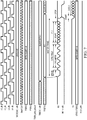
- Figure 1 illustrates an example transmission of the first through 512th byte, in accordance with certain embodiments of the present disclosure.
- Each byte transmitted will produce an interrupt event when a particular signal, (e.g., USE_FIFO) is set to a particular logic level (e.g., 0).
- the interrupt frequency may alter when that signal is altered. For example, when the signal is set to the opposite logic level (e.g., 1), the interrupt frequency may depend on the Watermark Setting.
- a BREAK character e.g., at least 11 clocks wide.
- the UART After the Start code, the UART will receive the 1st through 512th byte. Rather than have 512 interrupts for the received bytes, the UART is able to ignore the received bytes until the one that is of interest is received. This is done using other memory portions of the UART (e.g., the P2 and P3 registers).
- One memory portion e.g., the P2 register
- One memory portion may hold the value of the byte number to start the receive process.
- a user may program the P2 register to 10.
- the Lighting fixture discussed earlier may be programmed to number 22.
- Another memory portion (e.g., register P3) may hold the value for the number of bytes to receive.
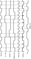
- FIG. 2 illustrates an example corresponding DMX receive protocol, in accordance with certain embodiments of the present disclosure.
- the UART with automated DMX protocol may also include a transmit software model.
- the transmit software model may be set up by asserting a particular signal.
- a pin signal e.g., P1H/L
- P1H/L may be set to a desired duration for the transmitted BREAK.
- a typical value is 13.
- the model may then write the Start Code into a communication bus (e.g., TXB[7:0]). This may make the UART transmit the BREAK when the first word is written into the FIFO.
- the BREAK may last for the desired duration (e.g., by the number of clock counts set on 'P1H/L').
- the UART may then write the remaining Channels into the communication bus (e.g., TXB[7:0]).
- the transmission output may go high and stay high until more bus contents become available. This may result in a transmission timer reset signal (e.g., uart_timer_reset_tx) from not toggling until more space on the bus is made available.
- An external Timer such as Timer 2
- the UART may automatically handle the MAB and 2-STOP Bits.
- the UART with automated DMX protocol may also include a receive software model.
- the receive software model may be set up by asserting a particular signal. For example, a first pin signal (e.g., P2H/L) may be set to a desired byte count to start receiving data. Additionally, a second pin signal (e.g., P3H/L) may be set to a desired count of bytes to receive starting at the first pin signal.
- the UART may wait for a BREAK to appear on the line. When it does, the sampling clock may be synchronized.
- the first byte received is the START code and is always loaded into the FIFO.
- a receive watermark interrupt signal (e.g., int_rx) is always flagged when the START code is received regardless of Watermark/FIFO setting. Starting from the byte after the Start code, the byte count (address) is specified by the first pin signal is matched. Once matched, the value on the second pin signal may be loaded into the FIFO.
- a receive watermark interrupt signal (e.g., int_rx) may be set the interrupt whenever the Watermark is reached. If the receive line is idle for more than a predetermined time (e.g., one second), the DMX link may be considered dead. An external timer may be used to time this predetermined time if the UART does not have a timer large enough to count to the predetermined time.
- the UART with automated protocol may take advantage of a DALI protocol.
- the particular protocol may be chosen by a plurality of bits that allow a user to select one of a plurality of available protocol modes. For example, a particular configuration may select the DALI protocol by setting a "USE_PROT" signal to a logic high.
- DALI is a protocol used to control lighting in large buildings such as offices and factories. It consists of two modes: “Devices" and "Gear.” A “Device” is the main controller that sends out commands to the lighting fixtures. The lighting fixture itself is known as "Gear.” All bit transmission may be done in Manchester Encoding, which is done by the hardware.
- the DALI wire is half-duplex; the transmit and receive lines are electrically tied together through an AC transformer.
- DALI is transmitted most significant bit (“MSb") first.
- the UART transaction may begin when the "Device” starts a transmission.
- a Device transmission consists of 2 Bytes in DALI 1.0 and 3 Bytes in DALI 2.0. The first one is a control byte designated by 'YAAAAAAS' followed by one or two data bytes. These bytes coming out of the Device is called a "Forward Frame".
- the interrupt frequency may depend on the Watermark Setting.
- an interrupt signal e.g., int_tx or TXBE/TXBF
- TXMTIF interrupt collision signal
- the UART When in DALI mode, the UART must make sure that both STOP bits are correctly received before the current byte is considered a valid receive. If either STOP bit is not correctly received, the receive byte is discarded before transferring from the shifter to the RXB.
- the UART hardware will detect the required number of STOP bits and respond with an error to the user if that number is not detected.
- the UART with automated DALI protocol may include a device software model.
- the device software model may be set up by asserting a particular signal. For example, a pin signal (e.g., P1H/L) may be set to a desired number of clock cycles between Forward Frames. Typically, this value will be eleven or greater.
- the UART may then transmit data (e.g., on X[7:0] immediately following YAAAAAAS. Therefore both bytes must be available before transmission can begin.
- the UART may then write the value of 'YAAAAAAS' header into a portion of the transmission bus (e.g., TXB[7:0]). Since this is the first write into the bus, it may immediately be copied into the transmission shifter, freeing up one location on the bus.
- the UART may then write the value of the data byte from the transmit data (e.g., on X[7:0]) onto the transmission bus (e.g., onto TXB[7:0]). If a 24-bit DALI 2.0 transmission is desired, a third byte must be written into the bus before the transmission shifter becomes empty. If the bus remains empty, a transmission line may go high and stay high.
- the UART may wait for the number of clocks between frames specified on the pin signal (e.g., P1H/L). During this time, the transmission output is held high. For DALI, this value is eleven, which will make the UART wait for eleven clocks to wait for a Back Frame.
- the UART may then transmit the next channels out of the transmission bus FIFO.
- a transmit watermark interrupt signal (e.g., int_tx) may trigger an interrupt whenever the Watermark is reached.
- the UART may make sure that a Header-Data byte pair is present before starting transmission for each Frame.
- the UART may automatically generate Manchester timing.
- the UART with automated DALI protocol may include a gear software model.
- the gear software model may be set up by asserting a particular signal.
- a pin signal e.g., P1H/L
- P1H/L may be set to a desired maximum number of clock cycles after Forward Frames to start a Back Frame. Typically, this value must be less than eleven (e.g., twenty-two half-bit times).
- the UART may begin listening for a Received Forward Frame. This is needed because a Forward Frame must be received before a Back Frame is transmitted.
- a Forward Frame is received, it is processed by the Application software.
- the value of the Back frame is written into a portion of the transmission bus (e.g., TXB[7:0]).
- the UART may ensure that fewer than the desired maximum number of clock cycles after the Forward Frame has passed. If the bus word is made available before this time expires, it is transmitted as a Back Frame. If more than that has passed, the content of the shifter is discarded. The word will be transferred from the bus into the transmission Shifter, but it will not be transmitted. For the next Back Frame, a new bus word must be written onto the bus by the user.
- the UART may wait for another Forward Frame. During this time, the transmission output may be held high. The UART may then transmit the next channels out of the bus FIFO when the next Forward Frame is received.
- the transmit watermark interrupt signal (e.g., int_tx) may trigger an interrupt whenever the Watermark is reached.
- the UART with automated protocol may take advantage of a LIN protocol.
- the particular protocol may be chosen by a plurality of bits that allow a user to select one of a plurality of available protocol modes. For example, a particular configuration may select the LIN protocol by setting a "USE_PROT" signal to a logic high.
- LIN is a protocol used in Automotive Applications.
- the LIN network consists of two kinds of software processes: a "Master” process and a "Slave” process. Each network only has one Master process and has one or more Slave processes.
- the Master process resides on one processor UART. All the other UARTs on the network are driven by Slave Software processes. From a physical layer point of view, the UART macro on one processor may be driven by both a Master and a Slave process, as long as only one Master process exists on one network.
- the UART begins when a Master process starts a transmission by transmitting a Break, followed by a Delimiter bit, followed by a Sync Field and protected identification ("PID") byte.
- the PID determines which Slave Process is expected to respond to the Master. After the PID byte is an Interbyte Space, whose length is set by a memory portion of the UART (e.g., the P3 register). Before the Interbyte Space expires, one or more of the Slave processes may respond to the Master Process. If no one responds within the Interbyte Space, the Master is free to start another transmission.
- the Slave Software process may drive the same UART as the Master, or may reside on another UART or another processor device altogether.
- the Slave Process starts by waiting for a Master Frame. If the PID matches, the Slave process responds by either doing nothing, or by transmitting the required response.
- up to eight bytes may be transmitted by the slave.
- the Slave UART automatically calculates the Checksum for the transmitted words, and transmits it as a data byte at the end of those bytes (e.g., at the 9th data byte), which completes the LIN transaction.
- the Checksum may be calculated by adding additional bits (e.g., eight bits) at a time and adding the carry bit to the result. This Checksum may then be transmitted with the transmission data.
- the Checksum is calculated using the same algorithm.
- the next byte (e.g., the ninth byte), which is the checksum value calculated by the transmitter is inverted and added to the locally calculated checksum. For example, if the result is all '1's, then the checksum has passed.
- Table 1 below illustrates an example taken from the LIN 2.2A specification. Table 1 uses the example values for the four data bytes involved in the calculation are 0x4A, 0x55, 0x93, 0xE5.
- Checksum may be available: Legacy and Enhanced.
- legacy checksum only data bytes D0 through D7 are used to calculate checksum.
- Enhanced Checksum data D0 through D7 and PID are included. Which checksum is used in the calculation can be controlled by software using a particular bit (e.g., a C0EN bit).
- the UART with automated LIN protocol may include a transmit software model.
- the transmit software model may be set up by asserting a particular signal. For example, a pin signal (e.g., P2H/L) may be set to a desired number of bytes to transmit.
- a pin signal e.g., P2H/L
- the Master Process may load a value (e.g., on P1L[5:0]) for the PID to be transmitted.
- the slave process may write up to eight bytes to be transmitted into the transmission bus FIFO.
- the value may be ignored since no PID transmission is needed.
- writing the PID value may begin a transmission process.
- the transmission process may include a Break, followed by a SYNC byte, followed by contents of the loaded value (e.g., from P1L[5:0]).
- PID values may be calculated by the hardware and transmitted.
- the UART may check the transmission bus occupancy. If the bus is not empty, that means a Slave process resides on the UART that want to transmit out bytes. The bytes in the bus are transmitted out until the number of transmit bytes stored on the pin signal (e.g., P2H).
- a transmit output (e.g., TXS) may be held high until either the bus is written, or the contents of the loaded value are written, whichever comes first. If the loaded value (e.g., P1L) is written, it is assumed that the Master is starting a new frame, the checksum/parity engine is reset and the whole BREAK-SYNC transmission process starts again.
- TXS transmit output
- a transmit watermark interrupt signal (e.g., int_tx) may trigger an interrupt whenever the Watermark is reached.
- the UART with automated LIN protocol may include a receive software model for certain slave-only modes.
- the transmit software model may be set up by asserting a particular signal.
- a pin signal e.g., P3H/L
- the UART may wait for a BREAK to appear on the line.
- the sampling clock is synchronized with the Sync Frame.
- a receive interrupt collision signal (e.g., RXBIF) is flagged, checksum and parity calculators are reset.
- the first byte received is PID.
- the receive interrupt (e.g., int_rx) is always flagged when the PID is received regardless of Watermark/FIFO setting.
- a UART may automatically calculate and verify other values (e.g., P0 and P1). If they disagree, a collision interrupt signal (e.g., PERIF) may be flagged. Incoming bytes are received until the number of bytes from the pin signal (e.g., P3H/L) are received.
- a certain bit (e.g., C0EN) must be set to the correct value before the start bit of the last byte in the packet is received.
- the receive watermark interrupt signal (e.g., int_rx) will trigger an interrupt whenever the Watermark is reached.
- the UART may automatically calculate a check sum (e.g., Checksum0 or 1) and XOR with the received Checksum to get all Is.
- the locally calculated Checksum may be stored in a memory portion (e.g., the UxRXCHK register).
- the checksum received from the receive input may be stored in the receive bus as if it was data.
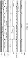
- Figure 5 illustrates an example timing diagram of a LIN master/slave mode, in accordance with certain embodiments of the present disclosure.
- Figure 6 illustrates a continuing example timing diagram of a LIN master/slave mode, in accordance with certain embodiments of the present disclosure.
- Figure 7 illustrates an example timing diagram of a LIN slave only mode, in accordance with certain embodiments of the present disclosure.
- Figure 8 illustrates a continuing example timing diagram of a LIN slave only mode, in accordance with certain embodiments of the present disclosure.
- the UART may operate in an Asynchronous Address Detect Mode.
- the Asynchronous Address Detect Mode may be used for modes where there are multiple receivers connected to one bus. When a transmitter transmits on this bus, it is useful for every receiver to know whether or not it is being addressed. This allows each receiving UART to eliminate unnecessary interrupts to its CPU.
- the UART may include an address detect transmission software model. In some embodiments, this model may be set up by setting a MODE signal. For example, MODE may be set to choose Asynchronous 9-bit mode with address detect ('0101').
- the UART may instigate a BREAK transmission. For example, the UART may write a logical one to the SENDB bit. Writing into a memory portion (e.g., P1 register) immediately after the SENDB will cause BREAK to be transmitted. Once BREAK transmission is completed, the SENDB bit may be auto-cleared. This may be followed by an eight-bit value of the memory portion (e.g., P1) to be transmitted. The ninth bit may be automatically transmitted as 1.
- a memory portion e.g., P1 register
- the SENDB bit may be auto-cleared. This may be followed by an eight-bit value of the memory portion (e.g., P1) to be transmitted.
- the ninth bit may be automatically transmitted as 1.
- the memory portion e.g., P1 register
- the SENDB bit can be ignored, or written to zero.
- Writing into the memory portion may cause the eight-bit value of the contents of the memory portion (e.g., P1) to be transmitted with the ninth bit automatically transmitted as one. This is an address transmission.
- Writing into the transmission bus register will cause the eight-bit value of the transmission bus to be transmitted with the ninth bit automatically transmitted as zero. This is a data transmission. The decision of what to transmit first depends on whether the memory portion (e.g., P1 register) is written. If both the memory portion (e.g., P1) and transmission bus are written, the contents of the memory portion (e.g., P1) are transmitted followed by any contents of the transmission bus.
- the UART may include an address detect receive software model.
- this model may be set up by setting a MODE signal.
- MODE may be set to choose an Asynchronous nine-bit mode with address detect ('0101').
- the UART may set up a first memory portion (e.g., P2) with the address to match.
- a second memory portion e.g., P3 may be set as an address mask.
- P2 a '0000 0000' to P3.
- the raw received address is loaded into the received FIFO. Any data (an eight-bit byte with the ninth bit set to zero) that follows is then loaded into the receive FIFO. This process continues until another address (e.g., an eight-bit byte with the ninth bit set to one) that mismatches with the contents of the first memory portion (e.g., P2) is received.
- the UART with automated protocol may take advantage of an asynchronous Manchester protocol.
- the particular protocol may be chosen by a plurality of bits that allow a user to select one of a plurality of available protocol modes. For example, a particular configuration may select the Manchester protocol by setting "USE_PROT" to a logic high. This mode is the generic UART connection mode, except that all the bits are Manchester-encoded by hardware. The same hardware used in DALI mode may be re-used here.
- the user may write transmit words into the transmission bus (e.g., TXB ⁇ 7:0>) in the transmit direction.
- a low-to-high start bit, followed by the contents of the bus may then be transmitted.
- the receive direction as each word is received, it is loaded in to the receive bus (e.g., RXB ⁇ 7:0>) and decoded from the incoming Manchester.
- USE_FIFO 1
- the interrupt frequency depends on the Watermark Setting.
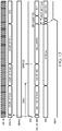
- Figure 9 illustrates an example Manchester decoding scheme for transmission, in accordance with certain embodiments of the present disclosure.
- Figure 10 illustrates an example Manchester decoding scheme for receiving, in accordance with certain embodiments of the present disclosure.
- Figure 11 illustrates a continuing example Manchester decoding scheme for receiving, in accordance with certain embodiments of the present disclosure.
- Figure 12 illustrates a further continuing example Manchester decoding scheme for receiving, in accordance with certain embodiments of the present disclosure.
- Figure 13 illustrates a still further example Manchester decoding scheme for receiving, in accordance with certain embodiments of the present disclosure.
- the clock rate for receive data may be different from that of transmission data; therefore it may be necessary to maintain a separate register to count clocks coming out of BRG. In these timing diagrams this register may be called BRG-RX. This is an internal register and is not available to read or write in the SFR space.
- the UART can decode Manchester encoding using hardware. Software does not have to be invoked to handle a high-to-low transitions of a Manchester decoding scheme. Rather, the UART simply receives recovered data bits. This allows Manchester transmissions of an unlimited (back-to-back) number of bytes, with no need for breaks between bytes.
- the UART with automated protocol may take advantage of a transmission software model.
- model may begin with the UART writing the words to be transmitted into the transmission bus. This may cause the START to be output, which is a low to high transition, followed by one byte of data.
- the bits are transmitted back to back with no START bit in between them. This allows an unlimited number of bytes to be transmitted back to back after the START bit.
- the shifter goes empty, the transmission line goes inactive.
- the UART will transmit a new START bit followed by the transmission bus word and the cycle repeats.
- the UART with automated protocol may take advantage of a receive software model.
- model may begin with an inactive (1) followed by a Manchester '1' (low to high). The Manchester half bit time is derived from the first low transition. Any data received is decoded from Manchester and loaded into the receive FIFO.
Landscapes
- Engineering & Computer Science (AREA)
- Theoretical Computer Science (AREA)
- Physics & Mathematics (AREA)
- General Engineering & Computer Science (AREA)
- General Physics & Mathematics (AREA)
- Information Transfer Systems (AREA)
- Communication Control (AREA)
- Synchronisation In Digital Transmission Systems (AREA)
Applications Claiming Priority (3)
| Application Number | Priority Date | Filing Date | Title |
|---|---|---|---|
| US201562181533P | 2015-06-18 | 2015-06-18 | |
| US15/185,257 US10331610B2 (en) | 2015-06-18 | 2016-06-17 | UART with automated protocols |
| PCT/US2016/038312 WO2016205776A1 (en) | 2015-06-18 | 2016-06-20 | Uart with automated protocols |
Publications (2)
| Publication Number | Publication Date |
|---|---|
| EP3311296A1 EP3311296A1 (en) | 2018-04-25 |
| EP3311296B1 true EP3311296B1 (en) | 2020-12-23 |
Family
ID=56289610
Family Applications (1)
| Application Number | Title | Priority Date | Filing Date |
|---|---|---|---|
| EP16733274.1A Active EP3311296B1 (en) | 2015-06-18 | 2016-06-20 | Uart with automated protocols |
Country Status (7)
| Country | Link |
|---|---|
| US (1) | US10331610B2 (enExample) |
| EP (1) | EP3311296B1 (enExample) |
| JP (1) | JP2018524859A (enExample) |
| KR (1) | KR20180019544A (enExample) |
| CN (1) | CN107771329A (enExample) |
| TW (1) | TW201709080A (enExample) |
| WO (1) | WO2016205776A1 (enExample) |
Families Citing this family (6)
| Publication number | Priority date | Publication date | Assignee | Title |
|---|---|---|---|---|
| CN107066412B (zh) * | 2017-05-27 | 2023-05-02 | 梦孚(上海)教育科技有限公司 | 一种通信电路及其方法 |
| CN107346298A (zh) * | 2017-07-11 | 2017-11-14 | 郑州云海信息技术有限公司 | 一种并行总线与uart总线间协议转换的方法及系统 |
| CN109152137B (zh) * | 2018-09-03 | 2020-12-15 | 深圳市汇德科技有限公司 | 一种基于led控制系统的抗干扰解码装置和一种led控制系统 |
| JP7369950B2 (ja) * | 2020-02-27 | 2023-10-27 | パナソニックIpマネジメント株式会社 | 照明器具および照明制御システム |
| EP4047485B1 (en) * | 2021-02-17 | 2023-09-06 | Aptiv Technologies Limited | Lin master testing device |
| CN113778920B (zh) * | 2021-11-12 | 2022-02-08 | 湖南双菱电子科技有限公司 | 一种嵌入式处理器串口通信方法和软件开发工具包 |
Family Cites Families (11)
| Publication number | Priority date | Publication date | Assignee | Title |
|---|---|---|---|---|
| US5371736A (en) | 1992-12-21 | 1994-12-06 | Abb Power T&D Company, Inc. | Universal protocol programmable communications interface |
| DE69533599T2 (de) * | 1994-02-02 | 2005-10-13 | Advanced Micro Devices, Inc., Sunnyvale | Leistungssteuerung in einem asynchronen Sender/Empfänger |
| US6263033B1 (en) * | 1998-03-09 | 2001-07-17 | Advanced Micro Devices, Inc. | Baud rate granularity in single clock microcontrollers for serial port transmissions |
| JP2003115888A (ja) * | 2001-10-05 | 2003-04-18 | Matsushita Electric Ind Co Ltd | 通信条件の自動設定方法と通信装置および通信システム |
| SG134232A1 (en) * | 2006-01-05 | 2007-08-29 | Telechips Inc | Audio system, and usb/uart common communication system for the same |
| CN101127023B (zh) * | 2006-08-17 | 2010-05-26 | 四川维肯电子有限公司 | 一种多总线接口的通用异步串口扩展芯片 |
| CN101009619A (zh) * | 2006-12-28 | 2007-08-01 | 中国科学院计算技术研究所 | 一种无线传感器网络网关设备 |
| DE102008018808A1 (de) * | 2008-04-15 | 2009-10-22 | Ledon Lighting Jennersdorf Gmbh | Mikrocontroller optimierte Pulsweitenmodulation-(PWM)-Ansteuerung einer Licht emittierenden Diode(LED) |
| US8639851B2 (en) | 2012-05-02 | 2014-01-28 | Atmel Corporation | Serial bit processor |
| US10108578B2 (en) | 2013-09-11 | 2018-10-23 | Texas Instruments Incorporated | Single wire communications interface and protocol |
| US9788375B2 (en) * | 2013-11-28 | 2017-10-10 | Panasonic Intellectual Property Management Co., Ltd. | Lighting device and illumination apparatus using same |
-
2016
- 2016-06-17 US US15/185,257 patent/US10331610B2/en active Active
- 2016-06-20 WO PCT/US2016/038312 patent/WO2016205776A1/en not_active Ceased
- 2016-06-20 CN CN201680034759.9A patent/CN107771329A/zh active Pending
- 2016-06-20 TW TW105119335A patent/TW201709080A/zh unknown
- 2016-06-20 EP EP16733274.1A patent/EP3311296B1/en active Active
- 2016-06-20 KR KR1020177035534A patent/KR20180019544A/ko not_active Withdrawn
- 2016-06-20 JP JP2017561908A patent/JP2018524859A/ja active Pending
Non-Patent Citations (1)
| Title |
|---|
| None * |
Also Published As
| Publication number | Publication date |
|---|---|
| WO2016205776A1 (en) | 2016-12-22 |
| US10331610B2 (en) | 2019-06-25 |
| CN107771329A (zh) | 2018-03-06 |
| TW201709080A (zh) | 2017-03-01 |
| KR20180019544A (ko) | 2018-02-26 |
| US20160371220A1 (en) | 2016-12-22 |
| EP3311296A1 (en) | 2018-04-25 |
| JP2018524859A (ja) | 2018-08-30 |
Similar Documents
| Publication | Publication Date | Title |
|---|---|---|
| EP3311296B1 (en) | Uart with automated protocols | |
| CN105683936B (zh) | 具有多个从设备标识符的相机控制从设备 | |
| US9740655B2 (en) | Data transmission using a protocol exception state | |
| CN103218331B (zh) | 采用同步模式切换及帧优先级自动调整的总线装置及方法 | |
| US10241955B2 (en) | Dynamically adjustable multi-line bus shared by multi-protocol devices | |
| JP5563165B2 (ja) | 切り替え可能なデータレートによる直列データ伝送のための方法及び装置 | |
| US9300323B2 (en) | Method and device for serially transferring data, having switchable data encoding | |
| CN108885602A (zh) | 多协议i3c共用命令码 | |
| US9019959B2 (en) | Node, switch, and system | |
| JP2015536067A (ja) | 可変的なデータレート対応のコントローラエリアネットワーク | |
| US10579581B2 (en) | Multilane heterogeneous serial bus | |
| CN107408097A (zh) | 用于旧式和下一代设备在共享多模总线上共存的告别重置和重启方法 | |
| CN104995874B (zh) | 具有协议异常状态的数据传输协议 | |
| JP2018524859A5 (enExample) | ||
| CN105208021A (zh) | 一种数据通讯方法及其系统 | |
| WO2019070361A1 (en) | MULTI-LINE BUS WITH DYNAMIC ADJUSTMENT SHARED BY MULTIPROTOCOL DEVICES | |
| CN106330357B (zh) | 一种serdes的传输校验方法、节点与系统 | |
| WO2007060620A1 (en) | Synchronized receiver | |
| CN202385121U (zh) | 一种基于fsm的短距离家居通讯协议的控制系统 | |
| CN106603430A (zh) | 基于sopc的通用数据通信接口集成方法 | |
| CN111884987A (zh) | 电子设备和用于电子设备的方法 | |
| WO2004012405A2 (en) | Packet processing architecture | |
| CN107066412B (zh) | 一种通信电路及其方法 | |
| CN114788248B (zh) | 数据传输通道上通信参与方之间循环传输数据的方法及数据传输系统 | |
| CN1490734A (zh) | 一种紧凑型外围部件互连总线系统中控制平面的实现方法 |
Legal Events
| Date | Code | Title | Description |
|---|---|---|---|
| STAA | Information on the status of an ep patent application or granted ep patent |
Free format text: STATUS: THE INTERNATIONAL PUBLICATION HAS BEEN MADE |
|
| PUAI | Public reference made under article 153(3) epc to a published international application that has entered the european phase |
Free format text: ORIGINAL CODE: 0009012 |
|
| STAA | Information on the status of an ep patent application or granted ep patent |
Free format text: STATUS: REQUEST FOR EXAMINATION WAS MADE |
|
| 17P | Request for examination filed |
Effective date: 20180112 |
|
| AK | Designated contracting states |
Kind code of ref document: A1 Designated state(s): AL AT BE BG CH CY CZ DE DK EE ES FI FR GB GR HR HU IE IS IT LI LT LU LV MC MK MT NL NO PL PT RO RS SE SI SK SM TR |
|
| AX | Request for extension of the european patent |
Extension state: BA ME |
|
| DAV | Request for validation of the european patent (deleted) | ||
| DAX | Request for extension of the european patent (deleted) | ||
| STAA | Information on the status of an ep patent application or granted ep patent |
Free format text: STATUS: EXAMINATION IS IN PROGRESS |
|
| 17Q | First examination report despatched |
Effective date: 20190704 |
|
| REG | Reference to a national code |
Ref country code: DE Ref legal event code: R079 Ref document number: 602016050204 Country of ref document: DE Free format text: PREVIOUS MAIN CLASS: G06F0013420000 Ipc: G06F0013380000 |
|
| GRAP | Despatch of communication of intention to grant a patent |
Free format text: ORIGINAL CODE: EPIDOSNIGR1 |
|
| STAA | Information on the status of an ep patent application or granted ep patent |
Free format text: STATUS: GRANT OF PATENT IS INTENDED |
|
| RIC1 | Information provided on ipc code assigned before grant |
Ipc: G06F 13/38 20060101AFI20200525BHEP |
|
| INTG | Intention to grant announced |
Effective date: 20200616 |
|
| GRAJ | Information related to disapproval of communication of intention to grant by the applicant or resumption of examination proceedings by the epo deleted |
Free format text: ORIGINAL CODE: EPIDOSDIGR1 |
|
| STAA | Information on the status of an ep patent application or granted ep patent |
Free format text: STATUS: EXAMINATION IS IN PROGRESS |
|
| GRAR | Information related to intention to grant a patent recorded |
Free format text: ORIGINAL CODE: EPIDOSNIGR71 |
|
| GRAS | Grant fee paid |
Free format text: ORIGINAL CODE: EPIDOSNIGR3 |
|
| STAA | Information on the status of an ep patent application or granted ep patent |
Free format text: STATUS: GRANT OF PATENT IS INTENDED |
|
| GRAA | (expected) grant |
Free format text: ORIGINAL CODE: 0009210 |
|
| STAA | Information on the status of an ep patent application or granted ep patent |
Free format text: STATUS: THE PATENT HAS BEEN GRANTED |
|
| INTC | Intention to grant announced (deleted) | ||
| INTG | Intention to grant announced |
Effective date: 20201111 |
|
| AK | Designated contracting states |
Kind code of ref document: B1 Designated state(s): AL AT BE BG CH CY CZ DE DK EE ES FI FR GB GR HR HU IE IS IT LI LT LU LV MC MK MT NL NO PL PT RO RS SE SI SK SM TR |
|
| REG | Reference to a national code |
Ref country code: GB Ref legal event code: FG4D |
|
| REG | Reference to a national code |
Ref country code: DE Ref legal event code: R096 Ref document number: 602016050204 Country of ref document: DE |
|
| REG | Reference to a national code |
Ref country code: AT Ref legal event code: REF Ref document number: 1348399 Country of ref document: AT Kind code of ref document: T Effective date: 20210115 |
|
| REG | Reference to a national code |
Ref country code: IE Ref legal event code: FG4D |
|
| PG25 | Lapsed in a contracting state [announced via postgrant information from national office to epo] |
Ref country code: RS Free format text: LAPSE BECAUSE OF FAILURE TO SUBMIT A TRANSLATION OF THE DESCRIPTION OR TO PAY THE FEE WITHIN THE PRESCRIBED TIME-LIMIT Effective date: 20201223 Ref country code: NO Free format text: LAPSE BECAUSE OF FAILURE TO SUBMIT A TRANSLATION OF THE DESCRIPTION OR TO PAY THE FEE WITHIN THE PRESCRIBED TIME-LIMIT Effective date: 20210323 Ref country code: FI Free format text: LAPSE BECAUSE OF FAILURE TO SUBMIT A TRANSLATION OF THE DESCRIPTION OR TO PAY THE FEE WITHIN THE PRESCRIBED TIME-LIMIT Effective date: 20201223 Ref country code: GR Free format text: LAPSE BECAUSE OF FAILURE TO SUBMIT A TRANSLATION OF THE DESCRIPTION OR TO PAY THE FEE WITHIN THE PRESCRIBED TIME-LIMIT Effective date: 20210324 |
|
| REG | Reference to a national code |
Ref country code: AT Ref legal event code: MK05 Ref document number: 1348399 Country of ref document: AT Kind code of ref document: T Effective date: 20201223 |
|
| REG | Reference to a national code |
Ref country code: NL Ref legal event code: MP Effective date: 20201223 |
|
| PG25 | Lapsed in a contracting state [announced via postgrant information from national office to epo] |
Ref country code: LV Free format text: LAPSE BECAUSE OF FAILURE TO SUBMIT A TRANSLATION OF THE DESCRIPTION OR TO PAY THE FEE WITHIN THE PRESCRIBED TIME-LIMIT Effective date: 20201223 Ref country code: BG Free format text: LAPSE BECAUSE OF FAILURE TO SUBMIT A TRANSLATION OF THE DESCRIPTION OR TO PAY THE FEE WITHIN THE PRESCRIBED TIME-LIMIT Effective date: 20210323 Ref country code: SE Free format text: LAPSE BECAUSE OF FAILURE TO SUBMIT A TRANSLATION OF THE DESCRIPTION OR TO PAY THE FEE WITHIN THE PRESCRIBED TIME-LIMIT Effective date: 20201223 |
|
| PG25 | Lapsed in a contracting state [announced via postgrant information from national office to epo] |
Ref country code: NL Free format text: LAPSE BECAUSE OF FAILURE TO SUBMIT A TRANSLATION OF THE DESCRIPTION OR TO PAY THE FEE WITHIN THE PRESCRIBED TIME-LIMIT Effective date: 20201223 Ref country code: HR Free format text: LAPSE BECAUSE OF FAILURE TO SUBMIT A TRANSLATION OF THE DESCRIPTION OR TO PAY THE FEE WITHIN THE PRESCRIBED TIME-LIMIT Effective date: 20201223 |
|
| REG | Reference to a national code |
Ref country code: LT Ref legal event code: MG9D |
|
| PG25 | Lapsed in a contracting state [announced via postgrant information from national office to epo] |
Ref country code: RO Free format text: LAPSE BECAUSE OF FAILURE TO SUBMIT A TRANSLATION OF THE DESCRIPTION OR TO PAY THE FEE WITHIN THE PRESCRIBED TIME-LIMIT Effective date: 20201223 Ref country code: PT Free format text: LAPSE BECAUSE OF FAILURE TO SUBMIT A TRANSLATION OF THE DESCRIPTION OR TO PAY THE FEE WITHIN THE PRESCRIBED TIME-LIMIT Effective date: 20210423 Ref country code: SK Free format text: LAPSE BECAUSE OF FAILURE TO SUBMIT A TRANSLATION OF THE DESCRIPTION OR TO PAY THE FEE WITHIN THE PRESCRIBED TIME-LIMIT Effective date: 20201223 Ref country code: LT Free format text: LAPSE BECAUSE OF FAILURE TO SUBMIT A TRANSLATION OF THE DESCRIPTION OR TO PAY THE FEE WITHIN THE PRESCRIBED TIME-LIMIT Effective date: 20201223 Ref country code: SM Free format text: LAPSE BECAUSE OF FAILURE TO SUBMIT A TRANSLATION OF THE DESCRIPTION OR TO PAY THE FEE WITHIN THE PRESCRIBED TIME-LIMIT Effective date: 20201223 Ref country code: CZ Free format text: LAPSE BECAUSE OF FAILURE TO SUBMIT A TRANSLATION OF THE DESCRIPTION OR TO PAY THE FEE WITHIN THE PRESCRIBED TIME-LIMIT Effective date: 20201223 Ref country code: EE Free format text: LAPSE BECAUSE OF FAILURE TO SUBMIT A TRANSLATION OF THE DESCRIPTION OR TO PAY THE FEE WITHIN THE PRESCRIBED TIME-LIMIT Effective date: 20201223 |
|
| PG25 | Lapsed in a contracting state [announced via postgrant information from national office to epo] |
Ref country code: AT Free format text: LAPSE BECAUSE OF FAILURE TO SUBMIT A TRANSLATION OF THE DESCRIPTION OR TO PAY THE FEE WITHIN THE PRESCRIBED TIME-LIMIT Effective date: 20201223 Ref country code: PL Free format text: LAPSE BECAUSE OF FAILURE TO SUBMIT A TRANSLATION OF THE DESCRIPTION OR TO PAY THE FEE WITHIN THE PRESCRIBED TIME-LIMIT Effective date: 20201223 |
|
| REG | Reference to a national code |
Ref country code: DE Ref legal event code: R097 Ref document number: 602016050204 Country of ref document: DE |
|
| PG25 | Lapsed in a contracting state [announced via postgrant information from national office to epo] |
Ref country code: IS Free format text: LAPSE BECAUSE OF FAILURE TO SUBMIT A TRANSLATION OF THE DESCRIPTION OR TO PAY THE FEE WITHIN THE PRESCRIBED TIME-LIMIT Effective date: 20210423 |
|
| PG25 | Lapsed in a contracting state [announced via postgrant information from national office to epo] |
Ref country code: IT Free format text: LAPSE BECAUSE OF FAILURE TO SUBMIT A TRANSLATION OF THE DESCRIPTION OR TO PAY THE FEE WITHIN THE PRESCRIBED TIME-LIMIT Effective date: 20201223 Ref country code: AL Free format text: LAPSE BECAUSE OF FAILURE TO SUBMIT A TRANSLATION OF THE DESCRIPTION OR TO PAY THE FEE WITHIN THE PRESCRIBED TIME-LIMIT Effective date: 20201223 |
|
| PLBE | No opposition filed within time limit |
Free format text: ORIGINAL CODE: 0009261 |
|
| STAA | Information on the status of an ep patent application or granted ep patent |
Free format text: STATUS: NO OPPOSITION FILED WITHIN TIME LIMIT |
|
| PG25 | Lapsed in a contracting state [announced via postgrant information from national office to epo] |
Ref country code: DK Free format text: LAPSE BECAUSE OF FAILURE TO SUBMIT A TRANSLATION OF THE DESCRIPTION OR TO PAY THE FEE WITHIN THE PRESCRIBED TIME-LIMIT Effective date: 20201223 |
|
| 26N | No opposition filed |
Effective date: 20210924 |
|
| PG25 | Lapsed in a contracting state [announced via postgrant information from national office to epo] |
Ref country code: MC Free format text: LAPSE BECAUSE OF FAILURE TO SUBMIT A TRANSLATION OF THE DESCRIPTION OR TO PAY THE FEE WITHIN THE PRESCRIBED TIME-LIMIT Effective date: 20201223 Ref country code: ES Free format text: LAPSE BECAUSE OF FAILURE TO SUBMIT A TRANSLATION OF THE DESCRIPTION OR TO PAY THE FEE WITHIN THE PRESCRIBED TIME-LIMIT Effective date: 20201223 |
|
| REG | Reference to a national code |
Ref country code: CH Ref legal event code: PL |
|
| GBPC | Gb: european patent ceased through non-payment of renewal fee |
Effective date: 20210620 |
|
| PG25 | Lapsed in a contracting state [announced via postgrant information from national office to epo] |
Ref country code: SI Free format text: LAPSE BECAUSE OF FAILURE TO SUBMIT A TRANSLATION OF THE DESCRIPTION OR TO PAY THE FEE WITHIN THE PRESCRIBED TIME-LIMIT Effective date: 20201223 |
|
| REG | Reference to a national code |
Ref country code: BE Ref legal event code: MM Effective date: 20210630 |
|
| PG25 | Lapsed in a contracting state [announced via postgrant information from national office to epo] |
Ref country code: LU Free format text: LAPSE BECAUSE OF NON-PAYMENT OF DUE FEES Effective date: 20210620 |
|
| PG25 | Lapsed in a contracting state [announced via postgrant information from national office to epo] |
Ref country code: LI Free format text: LAPSE BECAUSE OF NON-PAYMENT OF DUE FEES Effective date: 20210630 Ref country code: IE Free format text: LAPSE BECAUSE OF NON-PAYMENT OF DUE FEES Effective date: 20210620 Ref country code: GB Free format text: LAPSE BECAUSE OF NON-PAYMENT OF DUE FEES Effective date: 20210620 Ref country code: CH Free format text: LAPSE BECAUSE OF NON-PAYMENT OF DUE FEES Effective date: 20210630 |
|
| PG25 | Lapsed in a contracting state [announced via postgrant information from national office to epo] |
Ref country code: IS Free format text: LAPSE BECAUSE OF FAILURE TO SUBMIT A TRANSLATION OF THE DESCRIPTION OR TO PAY THE FEE WITHIN THE PRESCRIBED TIME-LIMIT Effective date: 20210423 Ref country code: FR Free format text: LAPSE BECAUSE OF NON-PAYMENT OF DUE FEES Effective date: 20210630 |
|
| PG25 | Lapsed in a contracting state [announced via postgrant information from national office to epo] |
Ref country code: BE Free format text: LAPSE BECAUSE OF NON-PAYMENT OF DUE FEES Effective date: 20210630 |
|
| PG25 | Lapsed in a contracting state [announced via postgrant information from national office to epo] |
Ref country code: CY Free format text: LAPSE BECAUSE OF FAILURE TO SUBMIT A TRANSLATION OF THE DESCRIPTION OR TO PAY THE FEE WITHIN THE PRESCRIBED TIME-LIMIT Effective date: 20201223 |
|
| P01 | Opt-out of the competence of the unified patent court (upc) registered |
Effective date: 20230528 |
|
| PG25 | Lapsed in a contracting state [announced via postgrant information from national office to epo] |
Ref country code: HU Free format text: LAPSE BECAUSE OF FAILURE TO SUBMIT A TRANSLATION OF THE DESCRIPTION OR TO PAY THE FEE WITHIN THE PRESCRIBED TIME-LIMIT; INVALID AB INITIO Effective date: 20160620 |
|
| PG25 | Lapsed in a contracting state [announced via postgrant information from national office to epo] |
Ref country code: MK Free format text: LAPSE BECAUSE OF FAILURE TO SUBMIT A TRANSLATION OF THE DESCRIPTION OR TO PAY THE FEE WITHIN THE PRESCRIBED TIME-LIMIT Effective date: 20201223 |
|
| PG25 | Lapsed in a contracting state [announced via postgrant information from national office to epo] |
Ref country code: MT Free format text: LAPSE BECAUSE OF FAILURE TO SUBMIT A TRANSLATION OF THE DESCRIPTION OR TO PAY THE FEE WITHIN THE PRESCRIBED TIME-LIMIT Effective date: 20201223 |
|
| PGFP | Annual fee paid to national office [announced via postgrant information from national office to epo] |
Ref country code: DE Payment date: 20250520 Year of fee payment: 10 |