EP3311074B1 - Brenner mit verbrennungsluftbetriebener strahlpumpe - Google Patents
Brenner mit verbrennungsluftbetriebener strahlpumpe Download PDFInfo
- Publication number
- EP3311074B1 EP3311074B1 EP16812139.0A EP16812139A EP3311074B1 EP 3311074 B1 EP3311074 B1 EP 3311074B1 EP 16812139 A EP16812139 A EP 16812139A EP 3311074 B1 EP3311074 B1 EP 3311074B1
- Authority
- EP
- European Patent Office
- Prior art keywords
- jet pump
- combustion air
- flue gas
- fuel
- burner
- Prior art date
- Legal status (The legal status is an assumption and is not a legal conclusion. Google has not performed a legal analysis and makes no representation as to the accuracy of the status listed.)
- Active
Links
Images

Classifications
-
- F—MECHANICAL ENGINEERING; LIGHTING; HEATING; WEAPONS; BLASTING
- F23—COMBUSTION APPARATUS; COMBUSTION PROCESSES
- F23C—METHODS OR APPARATUS FOR COMBUSTION USING FLUID FUEL OR SOLID FUEL SUSPENDED IN A CARRIER GAS OR AIR
- F23C7/00—Combustion apparatus characterised by arrangements for air supply
- F23C7/02—Disposition of air supply not passing through burner
- F23C7/06—Disposition of air supply not passing through burner for heating the incoming air
-
- F—MECHANICAL ENGINEERING; LIGHTING; HEATING; WEAPONS; BLASTING
- F23—COMBUSTION APPARATUS; COMBUSTION PROCESSES
- F23C—METHODS OR APPARATUS FOR COMBUSTION USING FLUID FUEL OR SOLID FUEL SUSPENDED IN A CARRIER GAS OR AIR
- F23C9/00—Combustion apparatus characterised by arrangements for returning combustion products or flue gases to the combustion chamber
- F23C9/06—Combustion apparatus characterised by arrangements for returning combustion products or flue gases to the combustion chamber for completing combustion
-
- F—MECHANICAL ENGINEERING; LIGHTING; HEATING; WEAPONS; BLASTING
- F23—COMBUSTION APPARATUS; COMBUSTION PROCESSES
- F23C—METHODS OR APPARATUS FOR COMBUSTION USING FLUID FUEL OR SOLID FUEL SUSPENDED IN A CARRIER GAS OR AIR
- F23C9/00—Combustion apparatus characterised by arrangements for returning combustion products or flue gases to the combustion chamber
-
- F—MECHANICAL ENGINEERING; LIGHTING; HEATING; WEAPONS; BLASTING
- F23—COMBUSTION APPARATUS; COMBUSTION PROCESSES
- F23D—BURNERS
- F23D14/00—Burners for combustion of a gas, e.g. of a gas stored under pressure as a liquid
- F23D14/46—Details
- F23D14/62—Mixing devices; Mixing tubes
- F23D14/64—Mixing devices; Mixing tubes with injectors
-
- F—MECHANICAL ENGINEERING; LIGHTING; HEATING; WEAPONS; BLASTING
- F23—COMBUSTION APPARATUS; COMBUSTION PROCESSES
- F23J—REMOVAL OR TREATMENT OF COMBUSTION PRODUCTS OR COMBUSTION RESIDUES; FLUES
- F23J15/00—Arrangements of devices for treating smoke or fumes
-
- F—MECHANICAL ENGINEERING; LIGHTING; HEATING; WEAPONS; BLASTING
- F23—COMBUSTION APPARATUS; COMBUSTION PROCESSES
- F23C—METHODS OR APPARATUS FOR COMBUSTION USING FLUID FUEL OR SOLID FUEL SUSPENDED IN A CARRIER GAS OR AIR
- F23C2201/00—Staged combustion
- F23C2201/10—Furnace staging
- F23C2201/101—Furnace staging in vertical direction, e.g. alternating lean and rich zones
-
- F—MECHANICAL ENGINEERING; LIGHTING; HEATING; WEAPONS; BLASTING
- F23—COMBUSTION APPARATUS; COMBUSTION PROCESSES
- F23C—METHODS OR APPARATUS FOR COMBUSTION USING FLUID FUEL OR SOLID FUEL SUSPENDED IN A CARRIER GAS OR AIR
- F23C2202/00—Fluegas recirculation
- F23C2202/30—Premixing fluegas with combustion air
-
- F—MECHANICAL ENGINEERING; LIGHTING; HEATING; WEAPONS; BLASTING
- F23—COMBUSTION APPARATUS; COMBUSTION PROCESSES
- F23C—METHODS OR APPARATUS FOR COMBUSTION USING FLUID FUEL OR SOLID FUEL SUSPENDED IN A CARRIER GAS OR AIR
- F23C2900/00—Special features of, or arrangements for combustion apparatus using fluid fuels or solid fuels suspended in air; Combustion processes therefor
- F23C2900/09002—Specific devices inducing or forcing flue gas recirculation
Definitions
- the present disclosure relates to devices, methods, and systems utilizing a burner with a combustion air driven jet pump.
- Oxides of nitrogen in the form of Nitrogen Oxide (i.e., NO) and Nitrogen Dioxide (NO 2 ) are generated by the burning of fossil fuels.
- NOx Nitrogen Oxide
- NO 2 Nitrogen Dioxide
- Flue gas recycling is an industry accepted way to achieve low NOx emissions in fossil fuel fired combustion applications. Numerous field and laboratory studies have proven the beneficial effect of recycling flue gas using a variety of fossil fuel burner-sealed fired chamber test arrangements. However, the addition of flue gas recycling to any fired application requires increased equipment complexity, capital, and/or operational expense.
- One method to achieve flue gas recycling using premixed burners is to have the flue gas ducted back to a point near the combustion air intake where it can enter the combustion air fan to be mixed with the combustion air and fuel gas. This method requires additional piping and apparatus around the burner and boiler (or other sealed fired chamber).
- Another method, applicable to non-premixed burners, is to use an auxiliary fan to suction flue gas from the exhaust stack or fired chamber, and discharge that flue gas into the burner housing where it mixes with the incoming combustion air provided by the combustion air fan.
- This method requires additional flue gas piping and an additional corrosion resistant, high temperature rated fan to transport the hot flue gas.
- US5269679 discloses a gas-fired burner incorporating an air driven jet pump for mixing air, fuel, and recirculated flue gas is disclosed.
- the burner is configured for the staged introduction of combustion air to provide a fuel-rich combustion zone and a fuel-lean combustion zone.
- the burner achieves reduced NOx emission levels in high temperature applications which use preheated combustion air.
- US5413477 discloses a gas-fired burner incorporating an air driven jet pump for mixing air, fuel, and recirculated flue gas with reduced heat loss from the recirculated flue gas is disclosed.
- the burner is configured for the staged introduction of combustion air to provide a fuel-rich combustion zone and a fuel-lean combustion zone.
- Internal flue gas channels deliver cooled flue gas to the primary fuel-rich combustion zone.
- a valve assembly may be provided to control the flow of flue gas.
- Secondary air channels concentrically arranged within the flue gas channels deliver superheated, staged air to the secondary fuel-lean combustion zone. Heat is transferred from the hot flue gas to the counterflowing cooler secondary air.
- the burner achieves reduced NOx emission levels in high temperature applications which use preheated combustion air with no or minimal loss in thermal efficiency from flue gas recirculation.
- US4800866 discloses a radiant tube burner assembly comprising a radiant tube having a burner leg and an exhaust leg.
- a plenum for mixing combustion air and products of combustion from the exhaust leg is positioned to direct the resultant mixture into the burner leg.
- a jet pump for directing high velocity combustion air through a nozzle and along a central longitudinal axis of the plenum aspirates the products of combustion from the exhaust leg through a duct in registry with the plenum and the exhaust leg.
- a restricted orifice associated with the duct is dimensioned and sized in relation to the jet pump nozzle to control the amount of products of combustion aspirated to the plenum.
- a conventional fuel source including a fuel pipe and conventional exhaust means also form a part of the assembly.
- WO01/07833 discloses a reduction in NOx formation for high temperature applications with hot and regenerative combustion air is accomplished with flame control as follows.
- Initial NOx formation is reduced by introducing internally recirculated waste gases extracted directly from the chamber atmosphere adjacent to the burner quarl and a regulated air flow into the fuel stream. This stream of gases intersects with a ring of combustion air sufficient in flow rate to initiate the combustion process on the heavily diluted gas stream perimeter.
- Further reduction in NOx formation is accomplished by diluting the combustion air with "in chamber” waste gases.
- the lean burning gas stream is allowed to expand onto the hot face of an air baffle at which localised combustion takes place.
- the high velocity air streams exiting the air baffle induce waste gases into the overall mixture and the combustion process is completed with the desired air/fuel ratio in the furnace chamber.
- a burner apparatus according to the present invention is provided in claim 1. Further embodiments of the invention are provided in the dependent claims.
- FIG 1 is an angled overhead view of a burner with a combustion air driven jet pump according to one or more embodiments of the present invention.
- the burner apparatus 100 includes a combustion air inlet 102.
- Combustion air is air received from outside the apparatus for use in the combustion process (e.g., ambient air).
- Flue gas is also received through a flue gas inlet 104, for example, from the exhaust stack and/or firing chamber.
- the flue gas enters the burner apparatus via the inlet and progresses into a flue gas receiving chamber 112.
- the flue gas and combustion air are mixed in a narrowing portion of the chamber 114 used to convey the fluids (e.g., flue gas, combustion air).
- Fuel is also added into the chamber at fuel gas manifold 116 through a number of fuel ports 206-1, 206-2, 206-N.
- the fuel and flue gas-combustion air mixture are mixed to form a fuel-flue gas-combustion air mixture in a mixing portion of the chamber 118.
- the mixture is ignited and the flame and resultant flue gas exits the chamber at outlet 108.
- inventions of the present invention could be constructed, for example, of rolled and formed sheet metal, tubing, and/or pipe. In various embodiments, other suitable materials can be used.
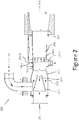
- Figure 2 is a cutaway side view of a burner with a combustion air driven jet pump according to one or more embodiments of the present invention.
- Figure 2 provides an example of the interior of a burner assembly (e.g., burner assembly 100 of the embodiment of Figure 1 ) 200.
- the burner apparatus 200 includes a combustion air inlet 202.
- the combustion air inlet includes a chamber that has a tapering portion 210 forming an air nozzle 211 with a diameter (d) at its innermost end.
- diameter can be a diameter of a fluid path having circular cross section or can be a measurement of a largest width of a fluid path having a non-circular cross section (e.g., oval, rectangular).
- the assembly can include a distribution element at or near the end of the air nozzle 211 (e.g., at or near the smallest diameter of the air nozzle).
- a perforated plate e.g., having a number of holes formed therein
- This can, for instance, act to keep the flue gas more uniformly distributed in a receiving chamber 212 before it is educted by the nozzle 211.
- Such a mechanism can cause the flue gas to be more uniformly fed into the jet pump, which can provide a better (more uniform) mixture into the mixing tube where fuel gas is added.
- Flue gas is received through a flue gas inlet 204.
- the flue gas enters the burner apparatus via the inlet and progresses into the flue gas receiving chamber 212, referred to herein generally as the jet pump bell, although the bell also includes tapering portion 214.
- the flue gas and combustion air are mixed in a narrowing portion of the chamber 214 used to convey the fluids (e.g., flue gas, combustion air).
- the chamber can be a constant diameter.
- the chamber can have the diameter D (with reference to Figure 2 ) for portions 212, 214, and 216.
- fuel is added into the chamber at an upstream location of the burner throat 216 through a number of fuel inlets 206-1, 206-2, 206-3, 206-4, 206-N (referred to generally as inlets 206).
- inlets 206 can, for example, be fuel jets or fuel ports.
- the fuel and flue gas-combustion air mixture are mixed to form a fuel-flue gas-combustion air mixture in a mixing portion of the burner throat 216 which has a diameter (D).
- the mixture is ignited and the flame and resultant flue gas exits at outlet 208.
- the apparatus can include a flame attachment ledge 218 that allows a surface on which the fuel-flue gas-combustion air mixture can be ignited.
- one burner apparatus includes a jet pump located inside a burner housing.
- the jet pump e.g., elements 202, 210, and 212
- the jet pump has a jet pump inlet 202 that is connected to a combustion air fan (not shown) but can be provided upstream of the inlet 202 of the burner housing (elements including 210, 211, 212, 214, 216).
- the combustion air fan provides a volume of combustion air and combustion air pressure sufficient to drive the jet pump.
- the burner apparatus utilizes a jet pump arrangement designed and located inside the burner housing (e.g., elements 212, 214, and 216).
- the jet pump inlet 202 is connected to the combustion air fan, which provides the combustion air volume and pressure to drive the pump.
- the jet pump bell 212 which receives air from the centrally positioned combustion air nozzle 211, creates a negative pressure condition when the combustion air fan is operating.
- This negative pressure once connected to the flue gas source (e.g., exhaust stack and/or fired chamber), can be used to pull flue gas from the flue gas source without the use of an additional fan or the need to upsize the combustion air fan.
- the flue gas source e.g., exhaust stack and/or fired chamber
- the flue gas enters the burner housing inside the jet pump bell 212.
- the flue gas is educted and mixed with the combustion air at chamber portion 214.
- the mixture then passes into the burner throat 216 where it can be mixed with fuel in various ways to provide a flame at the burner outlet 208.
- the burner throat 216 includes a number of fuel inlets 206 provided downstream from the jet pump, but on the upstream portion of the burner throat. In this way, the fuel can be dispersed and mixed in the burner throat before it is ignited.
- the fuel can be better dispersed into the flue gas-combustion air mixture passing through the burner throat. Further, if the inlets are arranged generally uniformly spaced from each other, the fuel can be more evenly disbursed.
- This fuel port (inlet) arrangement also utilizes the available fuel gas pressure and fuel port velocity to increase the negative pressure created by the jet pump.
- This fuel port arrangement also provides a means to mix the gaseous fuel with the combustion air-flue gas mixture. This increase in negative pressure (suction) allows larger volumes of flue gas to be drawn, which improves the NOx reduction mechanism, while using smaller transport ducting (e.g., elements 204, 212, 214, 216), among other benefits.
- the burner apparatus 200 can include a combustion air inlet 202 which communicates to a frustoconical nozzle 211 centered in the jet pump bell 212.
- the jet pump bell 212 has a larger diameter inlet end that connects to the flue gas source 204, and tapers at 214 to a smaller diameter outlet end that connects to a mixing tube 216 which extends downstream to the burner discharge end 208.
- the nozzle 211 with diameter (d) and mixing tube 216 with diameter (D) are sized and located according to the following ratios:
- the mixing tube can include a fuel gas manifold that surrounds the tube radially at some distance downstream from the entrance of the mixing tube 216.
- the inside wall of the manifold (also the mixing tube wall), can, for example, include a series of holes drilled radially and inward at an angle ranging from 0-90 degrees and directed downstream toward the burner exit 208. The angled nature of the holes allows the fuel to be introduced into the mixing tube in a downstream direction which can increase negative pressure and increase the amount of flue gas that can be drawn into the burner apparatus 200.
- Combustion air enters the nozzle inlet 202, accelerates and ejects into the center of the jet pump bell 212.
- the negative pressure generated by the higher velocity combustion air ejecting into the jet pump bell draws flue gas from the flue gas source.
- the mixture of flue gas and combustion air passes through the mixing tube for some distance before fuel gas is injected into the stream radially and, in some embodiments, at an angle downstream that creates an additional negative pressure to increase the overall suction that the device can provide.
- the fuel gas, combustion air, and flue gas mix are carried downstream to the burner discharge end, where the mixture is initially lit by a pilot or other ignition means.
- the resulting flame can be stabilized indefinitely by various flame stabilization methods known to people of normal skill in the art.
- a stabilizing ledge 218 can be provided to provide a flame attachment surface that may assist in stabilizing the flame.
- combustion air is moved from a larger volume area into a smaller volume area, thereby speeding the flow of the air toward the outlet of the jet pump.
- the negative pressure, within the jet pump bell, generated from the jet pump can be used to pull flue gas from one or more flue gas sources, such as an exhaust stack or fired chamber.
- supplemental or alternative negative pressure can be generated by a number of fuel inlets that direct fuel into the apparatus downstream from the jet pump bell.
- the fuel inlets can be angled to inject fuel in a downstream direction (away from the jet pump bell outlet) and thereby create a negative pressure that can pull flue gas into the jet pump bell.
- the burner apparatus has a burner throat portion, as discussed above, which is located downstream from the jet pump bell.
- the burner throat includes a number of fuel inlets provided downstream from the jet pump bell, but on an upstream portion of the burner throat.
- the flue gas is educted and mixed with the combustion air to provide a combustion air-flue gas mixture.
- This combustion air-flue gas mixture then passes into the burner throat where it is mixed with fuel to provide a flame at the burner outlet.
- the jet pump bell includes a tapered portion that tapers to an outlet having a smaller diameter than a maximum diameter of the jet pump bell. This structure can also aid in creating negative pressure similarly to the narrowing toward the outlet in the jet pump.
- the burner apparatus allows for the combustion air to provide negative pressure to draw flue gas into the apparatus for use in the combustion process without the use of additional or upgraded fans for either the combustion air path or the flue gas path.
- multiple fuel inlets are arranged around the circumference of the burner throat. This can allow for better mixing of the fuel with the combustion air-flue gas mixture. This can be especially true at the edges of the burner throat where an injector nearer to the central elongate axis of the throat may not be able to mix the fuel as well.
- the inlets can be arranged generally uniformly spaced from each other. This can also allow for better mixing of the fuel with the combustion air-flue gas mixture. According to the invention, the fuel inlets are provided downstream from the jet pump bell. This can be beneficial, for example, to allow for mixing of the fuel with the combustion air-flue gas mixture once those two items have been mixed.
- the fuel inlets can provide fuel gas pressure and fuel velocity, when fuel is injected by the fuel inlets, which supplements negative pressure created by the jet pump that is present within the burner throat. This can be particularly true when the inlets are directed downstream.
- the jet pump bell includes a tapered portion that tapers to an outlet having a smaller diameter than a maximum diameter of the jet pump bell. This can be beneficial in providing the negative pressure characteristics for pulling flue gas into the jet pump bell.
- the outlet of the jet pump has a diameter that is smaller than the diameter of the outlet of the jet pump bell. This can also be beneficial in providing the negative pressure characteristics for pulling flue gas into the jet pump bell.
- the jet pump outlet can be centrally positioned within the jet pump bell with respect to an elongate axis of the jet pump bell, in some embodiments. This can be beneficial, for example, because the flow through the apparatus can be more symmetrical and therefore mixing can be more uniform.
- the embodiments of the present invention provide a number of different ways to induce a negative pressure to pull flue gas into an apparatus in order to create a combustion air-flue gas mixture that can be combined with fuel gas.
- a or "a number of” something can refer to one or more such things.
- a number of resources can refer to one or more resources.
- designator "N”, as used herein, particularly with respect to reference numerals in the drawings, indicates that a number of the particular feature so designated can be included with a number of embodiments of the present invention.
Landscapes
- Engineering & Computer Science (AREA)
- Mechanical Engineering (AREA)
- General Engineering & Computer Science (AREA)
- Chemical & Material Sciences (AREA)
- Combustion & Propulsion (AREA)
- Physics & Mathematics (AREA)
- Thermal Sciences (AREA)
Claims (6)
- Brennervorrichtung (200), umfassend:ein Brennergehäuse;eine Strahlpumpe, die innerhalb des Brennergehäuses positioniert ist, wobei die Strahlpumpe eine Strahlpumpenglocke (212) und einen Verbrennungslufteinlass (202) aufweist, der Verbrennungsluft aufnimmt, eine Kammer zum Aufnehmen der Verbrennungsluft vom Verbrennungslufteinlass (202) und einen sich verjüngenden Abschnitt (210) der Kammer, der sich zu einem Strahlpumpenauslass (211) mit einem kleineren Durchmesser als der Durchmesser des Verbrennungslufteinlasses (202) verjüngt, wobei der Strahlpumpenauslass (211) innerhalb der Strahlpumpenglocke (212) positioniert ist, und das Pumpen der Verbrennungsluft in die Strahlpumpenglocke (212) ermöglicht, wobei der von der Strahlpumpe erzeugte Unterdruck innerhalb der Strahlpumpenglocke (212) verwendet werden kann, um Rauchgas aus mindestens einem von einem Abgasrohr oder einer befeuerten Kammer zu ziehen;wobei die Strahlpumpe ferner umfassteinen Rauchgaseinlass (204), der mit der Strahlpumpenglocke (212) verbunden ist, um zu ermöglichen, dass sich Rauchgas mit der Verbrennungsluft in der Strahlpumpenglocke (212) vermischt, um ein Verbrennungsluft-Rauchgasgemisch zu bilden;wobei die Brennervorrichtung ferner umfassteinen Brenneraustritt (216), der stromabwärts der Strahlpumpenglocke (212) positioniert ist; undeine Mehrzahl von Brennstoffeinlässen (206), die mit dem Brenneraustritt (216) verbunden ist, um zu ermöglichen, dass sich Brennstoff mit dem Verbrennungsluft/Rauchgas-Gemisch vermischt, um ein Verbrennungsluft-Rauchgas-Brennstoff-Gemisch zu bilden,wobei das Verbrennungsluft-Rauchgas-Brennstoff-Gemisch entzündet wird und die Flamme und das resultierende Rauchgas die Brennervorrichtung an einem Auslass (208) verlassen;wobei die Strahlpumpenglocke (212) einen sich verjüngenden Abschnitt einschließt, der sich zu einem Auslass verjüngt, der einen kleineren Durchmesser als ein maximaler Durchmesser der Strahlpumpenglocke aufweist,wobei die Mehrzahl von Brennstoffeinlässen (206) um einen Umfang des Brenneraustritts (216) und an einem stromaufwärtigen Abschnitt davon angeordnet ist.
- Vorrichtung nach Anspruch 1, wobei ein weiterer Unterdruck durch die Mehrzahl von Brennstoffeinlässen (206) erzeugt wird.
- Vorrichtung nach Anspruch 2, wobei das Rauchgas abgezogen und mit der Verbrennungsluft gemischt wird, um das Verbrennungsluft-Rauchgas-Gemisch bereitzustellen.
- Vorrichtung nach Anspruch 1, wobei die Brennstoffeinlässe (206) im Allgemeinen gleichmäßig voneinander beabstandet angeordnet sind.
- Vorrichtung nach Anspruch 2, wobei der Brenngasdruck und die Brennstoffgeschwindigkeit des durch die Brennstoffeinlässe (206) eingespritzten Brennstoffs den weiteren Unterdruck innerhalb des Brenneraustritts (216) erzeugen.
- Vorrichtung nach Anspruch 5, wobei der Auslass der Strahlpumpe einen Durchmesser aufweist, der kleiner als der Durchmesser des Auslasses der Strahlpumpenglocke (212) ist.
Applications Claiming Priority (2)
| Application Number | Priority Date | Filing Date | Title |
|---|---|---|---|
| US14/741,219 US9982885B2 (en) | 2015-06-16 | 2015-06-16 | Burner with combustion air driven jet pump |
| PCT/US2016/035689 WO2016204982A1 (en) | 2015-06-16 | 2016-06-03 | Burner with combustion air driven jet pump |
Publications (3)
| Publication Number | Publication Date |
|---|---|
| EP3311074A1 EP3311074A1 (de) | 2018-04-25 |
| EP3311074A4 EP3311074A4 (de) | 2019-02-13 |
| EP3311074B1 true EP3311074B1 (de) | 2021-09-01 |
Family
ID=57545603
Family Applications (1)
| Application Number | Title | Priority Date | Filing Date |
|---|---|---|---|
| EP16812139.0A Active EP3311074B1 (de) | 2015-06-16 | 2016-06-03 | Brenner mit verbrennungsluftbetriebener strahlpumpe |
Country Status (5)
| Country | Link |
|---|---|
| US (1) | US9982885B2 (de) |
| EP (1) | EP3311074B1 (de) |
| CN (1) | CN107750319B (de) |
| ES (1) | ES2890493T3 (de) |
| WO (1) | WO2016204982A1 (de) |
Families Citing this family (8)
| Publication number | Priority date | Publication date | Assignee | Title |
|---|---|---|---|---|
| US9982885B2 (en) * | 2015-06-16 | 2018-05-29 | Honeywell International Inc. | Burner with combustion air driven jet pump |
| US11226092B2 (en) * | 2016-09-22 | 2022-01-18 | Utilization Technology Development, Nfp | Low NOx combustion devices and methods |
| US20190120485A1 (en) * | 2017-10-19 | 2019-04-25 | Haier Us Appliance Solutions, Inc. | Fuel supply system for a gas burner assembly |
| US10451271B2 (en) | 2017-12-20 | 2019-10-22 | Honeywell International Inc. | Staged fuel burner with jet induced exhaust gas recycle |
| US10533741B2 (en) * | 2017-12-20 | 2020-01-14 | Honeywell International Inc. | Low NOx burner with exhaust gas recycle and partial premix |
| US11187408B2 (en) | 2019-04-25 | 2021-11-30 | Fives North American Combustion, Inc. | Apparatus and method for variable mode mixing of combustion reactants |
| CN111609402B (zh) * | 2020-05-09 | 2022-09-16 | 北京泷涛环境科技有限公司 | 燃烧器以及燃气锅炉 |
| TW202200935A (zh) * | 2020-06-23 | 2022-01-01 | 日商林內有限公司 | 氣體噴嘴及燃燒裝置 |
Family Cites Families (29)
| Publication number | Priority date | Publication date | Assignee | Title |
|---|---|---|---|---|
| US3927958A (en) | 1974-10-29 | 1975-12-23 | Gen Motors Corp | Recirculating combustion apparatus |
| US4130388A (en) * | 1976-09-15 | 1978-12-19 | Flynn Burner Corporation | Non-contaminating fuel burner |
| US4445842A (en) | 1981-11-05 | 1984-05-01 | Thermal Systems Engineering, Inc. | Recuperative burner with exhaust gas recirculation means |
| US4800866A (en) * | 1987-03-13 | 1989-01-31 | Bloom Engineering Company, Inc. | Low NOX radiant tube burner and method |
| US5195884A (en) * | 1992-03-27 | 1993-03-23 | John Zink Company, A Division Of Koch Engineering Company, Inc. | Low NOx formation burner apparatus and methods |
| US5240409A (en) * | 1992-04-10 | 1993-08-31 | Institute Of Gas Technology | Premixed fuel/air burners |
| US5413477A (en) | 1992-10-16 | 1995-05-09 | Gas Research Institute | Staged air, low NOX burner with internal recuperative flue gas recirculation |
| US5269679A (en) | 1992-10-16 | 1993-12-14 | Gas Research Institute | Staged air, recirculating flue gas low NOx burner |
| CA2124069A1 (en) | 1993-05-24 | 1994-11-25 | Boris M. Kramnik | Low emission, fixed geometry gas turbine combustor |
| US5636977A (en) | 1994-10-13 | 1997-06-10 | Gas Research Institute | Burner apparatus for reducing nitrogen oxides |
| US6106276A (en) * | 1996-09-10 | 2000-08-22 | National Tank Company | Gas burner system providing reduced noise levels |
| FR2788112B1 (fr) * | 1998-12-30 | 2001-06-08 | Total Raffinage Distribution | Appareil de type torchere et procede pour la combustion de gaz |
| KR20010009896A (ko) | 1999-07-14 | 2001-02-05 | 손재익 | 젯 펌프를 구비한 공업로용 가스 연소기 |
| AU6001300A (en) | 1999-07-23 | 2001-02-13 | Dyson Hotwork Limited | Improved industrial burner for fuel |
| US6383461B1 (en) | 1999-10-26 | 2002-05-07 | John Zink Company, Llc | Fuel dilution methods and apparatus for NOx reduction |
| US6383462B1 (en) * | 1999-10-26 | 2002-05-07 | John Zink Company, Llc | Fuel dilution methods and apparatus for NOx reduction |
| DE10309799A1 (de) | 2003-03-05 | 2004-09-23 | Sgl Acotec Gmbh | Verfahren und Vorrichtung zur Herstellung von Chlorwasserstoff |
| US7967600B2 (en) * | 2006-03-27 | 2011-06-28 | John Zink Company, Llc | Flare apparatus |
| US8408896B2 (en) * | 2007-07-25 | 2013-04-02 | Lummus Technology Inc. | Method, system and apparatus for firing control |
| CN201159471Y (zh) * | 2008-01-30 | 2008-12-03 | 上海开能新技术工程有限公司 | 高温烟气引射器 |
| DE102010010791A1 (de) * | 2010-03-09 | 2011-09-15 | Honeywell Technologies Sarl | Mischvorrichtung für einen Gasbrenner |
| CN201819226U (zh) * | 2010-08-20 | 2011-05-04 | 贵州航空发动机研究所 | 一种焚烧炉的引射混燃装置 |
| CN202521609U (zh) * | 2012-03-15 | 2012-11-07 | 哈尔滨金鑫电气有限责任公司 | 一种多功能蓄热式脉冲烧嘴 |
| CN203068521U (zh) * | 2013-01-18 | 2013-07-17 | 福建三能节能科技有限责任公司 | 一种引射吸风式燃烧器 |
| US20160025366A1 (en) * | 2013-05-24 | 2016-01-28 | Emerson Electric Co. | Facilitating Installation and/or Use of a Controller and/or Maintenance of a Climate Control System |
| CN203375450U (zh) * | 2013-06-08 | 2014-01-01 | 中国联合工程公司 | 一种烟气回流式高热值燃气蓄热烧嘴 |
| US9416966B2 (en) * | 2014-07-25 | 2016-08-16 | Flame Commander Corp. | Venturi nozzle for a gas combustor |
| US9982885B2 (en) * | 2015-06-16 | 2018-05-29 | Honeywell International Inc. | Burner with combustion air driven jet pump |
| US9749483B2 (en) * | 2015-11-13 | 2017-08-29 | Kabushiki Kaisha Toshiba | Image forming apparatus and method for displaying template in image forming apparatus |
-
2015
- 2015-06-16 US US14/741,219 patent/US9982885B2/en active Active
-
2016
- 2016-06-03 CN CN201680036094.5A patent/CN107750319B/zh active Active
- 2016-06-03 ES ES16812139T patent/ES2890493T3/es active Active
- 2016-06-03 WO PCT/US2016/035689 patent/WO2016204982A1/en not_active Ceased
- 2016-06-03 EP EP16812139.0A patent/EP3311074B1/de active Active
Also Published As
| Publication number | Publication date |
|---|---|
| EP3311074A4 (de) | 2019-02-13 |
| US9982885B2 (en) | 2018-05-29 |
| CN107750319A (zh) | 2018-03-02 |
| CN107750319B (zh) | 2021-04-09 |
| US20160370002A1 (en) | 2016-12-22 |
| WO2016204982A1 (en) | 2016-12-22 |
| EP3311074A1 (de) | 2018-04-25 |
| ES2890493T3 (es) | 2022-01-20 |
Similar Documents
| Publication | Publication Date | Title |
|---|---|---|
| EP3311074B1 (de) | Brenner mit verbrennungsluftbetriebener strahlpumpe | |
| EP3502559B1 (de) | Nox-armer brenner mit abgasrückführung und teilvormischung | |
| EP0657689B1 (de) | Brenner mit niedrigem NOx-Gehalt, mit abgestufter Luftzufuhr mit interner rekuperativer Rauchgasrückführung | |
| US4505666A (en) | Staged fuel and air for low NOx burner | |
| US7670135B1 (en) | Burner and method for induction of flue gas | |
| MXPA01006286A (es) | Metodos de dilucion de combustibles y aparatos para la reduccion de nox. | |
| NO155116B (no) | Fremgangsmaate og anordning for ovnsfyring. | |
| CA2897422C (en) | Low nox combustion method and apparatus | |
| US5636977A (en) | Burner apparatus for reducing nitrogen oxides | |
| ZA200502379B (en) | Method and apparatus for heat treatment | |
| RU2689654C2 (ru) | Горелка | |
| JP2005521024A (ja) | NOx低放出の改良型バーナーシステム | |
| WO2012141982A1 (en) | Natural draft low swirl burner | |
| US10451271B2 (en) | Staged fuel burner with jet induced exhaust gas recycle | |
| US10006628B2 (en) | Low NOx gas burners with carryover ignition | |
| EP0076036B1 (de) | Verfahren und Vorrichtung zum Verbrennen von Brennstoff in Stufen | |
| US6893252B2 (en) | Fuel spud for high temperature burners | |
| US6866502B2 (en) | Burner system employing flue gas recirculation | |
| US9388983B2 (en) | Low NOx burner with low pressure drop | |
| JP4264003B2 (ja) | 改良型燃焼排ガス循環を使用するバーナーシステム | |
| US20050074711A1 (en) | Burner apparatus | |
| CN105531541A (zh) | 用于燃烧气体燃料或者液体燃料的燃烧器组件和方法 | |
| EP3714208B1 (de) | Wand-strahlungsbrenner | |
| EP4345373A1 (de) | Brennstoff-luft-misch- und flammenstabilisierungsvorrichtung für einen emissionsarmen brenner mit interner rauchgasrückführung | |
| WO2015172899A1 (en) | Method for operating a burner and combustion system |
Legal Events
| Date | Code | Title | Description |
|---|---|---|---|
| STAA | Information on the status of an ep patent application or granted ep patent |
Free format text: STATUS: THE INTERNATIONAL PUBLICATION HAS BEEN MADE |
|
| PUAI | Public reference made under article 153(3) epc to a published international application that has entered the european phase |
Free format text: ORIGINAL CODE: 0009012 |
|
| STAA | Information on the status of an ep patent application or granted ep patent |
Free format text: STATUS: REQUEST FOR EXAMINATION WAS MADE |
|
| 17P | Request for examination filed |
Effective date: 20171212 |
|
| AK | Designated contracting states |
Kind code of ref document: A1 Designated state(s): AL AT BE BG CH CY CZ DE DK EE ES FI FR GB GR HR HU IE IS IT LI LT LU LV MC MK MT NL NO PL PT RO RS SE SI SK SM TR |
|
| AX | Request for extension of the european patent |
Extension state: BA ME |
|
| DAV | Request for validation of the european patent (deleted) | ||
| DAX | Request for extension of the european patent (deleted) | ||
| A4 | Supplementary search report drawn up and despatched |
Effective date: 20190115 |
|
| RIC1 | Information provided on ipc code assigned before grant |
Ipc: F23C 9/00 20060101ALI20190109BHEP Ipc: F23D 1/00 20060101AFI20190109BHEP |
|
| STAA | Information on the status of an ep patent application or granted ep patent |
Free format text: STATUS: EXAMINATION IS IN PROGRESS |
|
| 17Q | First examination report despatched |
Effective date: 20200407 |
|
| GRAP | Despatch of communication of intention to grant a patent |
Free format text: ORIGINAL CODE: EPIDOSNIGR1 |
|
| STAA | Information on the status of an ep patent application or granted ep patent |
Free format text: STATUS: GRANT OF PATENT IS INTENDED |
|
| INTG | Intention to grant announced |
Effective date: 20210423 |
|
| GRAS | Grant fee paid |
Free format text: ORIGINAL CODE: EPIDOSNIGR3 |
|
| GRAA | (expected) grant |
Free format text: ORIGINAL CODE: 0009210 |
|
| STAA | Information on the status of an ep patent application or granted ep patent |
Free format text: STATUS: THE PATENT HAS BEEN GRANTED |
|
| AK | Designated contracting states |
Kind code of ref document: B1 Designated state(s): AL AT BE BG CH CY CZ DE DK EE ES FI FR GB GR HR HU IE IS IT LI LT LU LV MC MK MT NL NO PL PT RO RS SE SI SK SM TR |
|
| REG | Reference to a national code |
Ref country code: GB Ref legal event code: FG4D |
|
| REG | Reference to a national code |
Ref country code: CH Ref legal event code: EP Ref country code: AT Ref legal event code: REF Ref document number: 1426606 Country of ref document: AT Kind code of ref document: T Effective date: 20210915 |
|
| REG | Reference to a national code |
Ref country code: DE Ref legal event code: R096 Ref document number: 602016063184 Country of ref document: DE |
|
| REG | Reference to a national code |
Ref country code: IE Ref legal event code: FG4D |
|
| REG | Reference to a national code |
Ref country code: LT Ref legal event code: MG9D |
|
| REG | Reference to a national code |
Ref country code: NL Ref legal event code: MP Effective date: 20210901 |
|
| REG | Reference to a national code |
Ref country code: ES Ref legal event code: FG2A Ref document number: 2890493 Country of ref document: ES Kind code of ref document: T3 Effective date: 20220120 |
|
| PG25 | Lapsed in a contracting state [announced via postgrant information from national office to epo] |
Ref country code: RS Free format text: LAPSE BECAUSE OF FAILURE TO SUBMIT A TRANSLATION OF THE DESCRIPTION OR TO PAY THE FEE WITHIN THE PRESCRIBED TIME-LIMIT Effective date: 20210901 Ref country code: SE Free format text: LAPSE BECAUSE OF FAILURE TO SUBMIT A TRANSLATION OF THE DESCRIPTION OR TO PAY THE FEE WITHIN THE PRESCRIBED TIME-LIMIT Effective date: 20210901 Ref country code: LT Free format text: LAPSE BECAUSE OF FAILURE TO SUBMIT A TRANSLATION OF THE DESCRIPTION OR TO PAY THE FEE WITHIN THE PRESCRIBED TIME-LIMIT Effective date: 20210901 Ref country code: BG Free format text: LAPSE BECAUSE OF FAILURE TO SUBMIT A TRANSLATION OF THE DESCRIPTION OR TO PAY THE FEE WITHIN THE PRESCRIBED TIME-LIMIT Effective date: 20211201 Ref country code: NO Free format text: LAPSE BECAUSE OF FAILURE TO SUBMIT A TRANSLATION OF THE DESCRIPTION OR TO PAY THE FEE WITHIN THE PRESCRIBED TIME-LIMIT Effective date: 20211201 Ref country code: HR Free format text: LAPSE BECAUSE OF FAILURE TO SUBMIT A TRANSLATION OF THE DESCRIPTION OR TO PAY THE FEE WITHIN THE PRESCRIBED TIME-LIMIT Effective date: 20210901 Ref country code: FI Free format text: LAPSE BECAUSE OF FAILURE TO SUBMIT A TRANSLATION OF THE DESCRIPTION OR TO PAY THE FEE WITHIN THE PRESCRIBED TIME-LIMIT Effective date: 20210901 |
|
| REG | Reference to a national code |
Ref country code: AT Ref legal event code: MK05 Ref document number: 1426606 Country of ref document: AT Kind code of ref document: T Effective date: 20210901 |
|
| PG25 | Lapsed in a contracting state [announced via postgrant information from national office to epo] |
Ref country code: PL Free format text: LAPSE BECAUSE OF FAILURE TO SUBMIT A TRANSLATION OF THE DESCRIPTION OR TO PAY THE FEE WITHIN THE PRESCRIBED TIME-LIMIT Effective date: 20210901 Ref country code: LV Free format text: LAPSE BECAUSE OF FAILURE TO SUBMIT A TRANSLATION OF THE DESCRIPTION OR TO PAY THE FEE WITHIN THE PRESCRIBED TIME-LIMIT Effective date: 20210901 Ref country code: GR Free format text: LAPSE BECAUSE OF FAILURE TO SUBMIT A TRANSLATION OF THE DESCRIPTION OR TO PAY THE FEE WITHIN THE PRESCRIBED TIME-LIMIT Effective date: 20211202 |
|
| PG25 | Lapsed in a contracting state [announced via postgrant information from national office to epo] |
Ref country code: AT Free format text: LAPSE BECAUSE OF FAILURE TO SUBMIT A TRANSLATION OF THE DESCRIPTION OR TO PAY THE FEE WITHIN THE PRESCRIBED TIME-LIMIT Effective date: 20210901 |
|
| PG25 | Lapsed in a contracting state [announced via postgrant information from national office to epo] |
Ref country code: IS Free format text: LAPSE BECAUSE OF FAILURE TO SUBMIT A TRANSLATION OF THE DESCRIPTION OR TO PAY THE FEE WITHIN THE PRESCRIBED TIME-LIMIT Effective date: 20220101 Ref country code: SM Free format text: LAPSE BECAUSE OF FAILURE TO SUBMIT A TRANSLATION OF THE DESCRIPTION OR TO PAY THE FEE WITHIN THE PRESCRIBED TIME-LIMIT Effective date: 20210901 Ref country code: SK Free format text: LAPSE BECAUSE OF FAILURE TO SUBMIT A TRANSLATION OF THE DESCRIPTION OR TO PAY THE FEE WITHIN THE PRESCRIBED TIME-LIMIT Effective date: 20210901 Ref country code: RO Free format text: LAPSE BECAUSE OF FAILURE TO SUBMIT A TRANSLATION OF THE DESCRIPTION OR TO PAY THE FEE WITHIN THE PRESCRIBED TIME-LIMIT Effective date: 20210901 Ref country code: PT Free format text: LAPSE BECAUSE OF FAILURE TO SUBMIT A TRANSLATION OF THE DESCRIPTION OR TO PAY THE FEE WITHIN THE PRESCRIBED TIME-LIMIT Effective date: 20220103 Ref country code: NL Free format text: LAPSE BECAUSE OF FAILURE TO SUBMIT A TRANSLATION OF THE DESCRIPTION OR TO PAY THE FEE WITHIN THE PRESCRIBED TIME-LIMIT Effective date: 20210901 Ref country code: EE Free format text: LAPSE BECAUSE OF FAILURE TO SUBMIT A TRANSLATION OF THE DESCRIPTION OR TO PAY THE FEE WITHIN THE PRESCRIBED TIME-LIMIT Effective date: 20210901 Ref country code: CZ Free format text: LAPSE BECAUSE OF FAILURE TO SUBMIT A TRANSLATION OF THE DESCRIPTION OR TO PAY THE FEE WITHIN THE PRESCRIBED TIME-LIMIT Effective date: 20210901 Ref country code: AL Free format text: LAPSE BECAUSE OF FAILURE TO SUBMIT A TRANSLATION OF THE DESCRIPTION OR TO PAY THE FEE WITHIN THE PRESCRIBED TIME-LIMIT Effective date: 20210901 |
|
| REG | Reference to a national code |
Ref country code: DE Ref legal event code: R097 Ref document number: 602016063184 Country of ref document: DE |
|
| PLBE | No opposition filed within time limit |
Free format text: ORIGINAL CODE: 0009261 |
|
| STAA | Information on the status of an ep patent application or granted ep patent |
Free format text: STATUS: NO OPPOSITION FILED WITHIN TIME LIMIT |
|
| PG25 | Lapsed in a contracting state [announced via postgrant information from national office to epo] |
Ref country code: DK Free format text: LAPSE BECAUSE OF FAILURE TO SUBMIT A TRANSLATION OF THE DESCRIPTION OR TO PAY THE FEE WITHIN THE PRESCRIBED TIME-LIMIT Effective date: 20210901 |
|
| 26N | No opposition filed |
Effective date: 20220602 |
|
| PG25 | Lapsed in a contracting state [announced via postgrant information from national office to epo] |
Ref country code: SI Free format text: LAPSE BECAUSE OF FAILURE TO SUBMIT A TRANSLATION OF THE DESCRIPTION OR TO PAY THE FEE WITHIN THE PRESCRIBED TIME-LIMIT Effective date: 20210901 |
|
| PG25 | Lapsed in a contracting state [announced via postgrant information from national office to epo] |
Ref country code: MC Free format text: LAPSE BECAUSE OF FAILURE TO SUBMIT A TRANSLATION OF THE DESCRIPTION OR TO PAY THE FEE WITHIN THE PRESCRIBED TIME-LIMIT Effective date: 20210901 |
|
| REG | Reference to a national code |
Ref country code: CH Ref legal event code: PL |
|
| PG25 | Lapsed in a contracting state [announced via postgrant information from national office to epo] |
Ref country code: LU Free format text: LAPSE BECAUSE OF NON-PAYMENT OF DUE FEES Effective date: 20220603 Ref country code: LI Free format text: LAPSE BECAUSE OF NON-PAYMENT OF DUE FEES Effective date: 20220630 Ref country code: IE Free format text: LAPSE BECAUSE OF NON-PAYMENT OF DUE FEES Effective date: 20220603 Ref country code: CH Free format text: LAPSE BECAUSE OF NON-PAYMENT OF DUE FEES Effective date: 20220630 |
|
| P01 | Opt-out of the competence of the unified patent court (upc) registered |
Effective date: 20230414 |
|
| PG25 | Lapsed in a contracting state [announced via postgrant information from national office to epo] |
Ref country code: HU Free format text: LAPSE BECAUSE OF FAILURE TO SUBMIT A TRANSLATION OF THE DESCRIPTION OR TO PAY THE FEE WITHIN THE PRESCRIBED TIME-LIMIT; INVALID AB INITIO Effective date: 20160603 |
|
| PG25 | Lapsed in a contracting state [announced via postgrant information from national office to epo] |
Ref country code: MK Free format text: LAPSE BECAUSE OF FAILURE TO SUBMIT A TRANSLATION OF THE DESCRIPTION OR TO PAY THE FEE WITHIN THE PRESCRIBED TIME-LIMIT Effective date: 20210901 Ref country code: CY Free format text: LAPSE BECAUSE OF FAILURE TO SUBMIT A TRANSLATION OF THE DESCRIPTION OR TO PAY THE FEE WITHIN THE PRESCRIBED TIME-LIMIT Effective date: 20210901 |
|
| PG25 | Lapsed in a contracting state [announced via postgrant information from national office to epo] |
Ref country code: MT Free format text: LAPSE BECAUSE OF FAILURE TO SUBMIT A TRANSLATION OF THE DESCRIPTION OR TO PAY THE FEE WITHIN THE PRESCRIBED TIME-LIMIT Effective date: 20210901 |
|
| PGFP | Annual fee paid to national office [announced via postgrant information from national office to epo] |
Ref country code: ES Payment date: 20240710 Year of fee payment: 9 |
|
| PGFP | Annual fee paid to national office [announced via postgrant information from national office to epo] |
Ref country code: DE Payment date: 20250626 Year of fee payment: 10 |
|
| PGFP | Annual fee paid to national office [announced via postgrant information from national office to epo] |
Ref country code: GB Payment date: 20250617 Year of fee payment: 10 |
|
| PGFP | Annual fee paid to national office [announced via postgrant information from national office to epo] |
Ref country code: BE Payment date: 20250624 Year of fee payment: 10 |
|
| PGFP | Annual fee paid to national office [announced via postgrant information from national office to epo] |
Ref country code: FR Payment date: 20250624 Year of fee payment: 10 |
|
| PGFP | Annual fee paid to national office [announced via postgrant information from national office to epo] |
Ref country code: IT Payment date: 20250623 Year of fee payment: 10 |