EP3310967B1 - Sicherheitsbarriere und verfahren zur herstellung einer sicherheitsbarriere - Google Patents
Sicherheitsbarriere und verfahren zur herstellung einer sicherheitsbarriere Download PDFInfo
- Publication number
- EP3310967B1 EP3310967B1 EP15733918.5A EP15733918A EP3310967B1 EP 3310967 B1 EP3310967 B1 EP 3310967B1 EP 15733918 A EP15733918 A EP 15733918A EP 3310967 B1 EP3310967 B1 EP 3310967B1
- Authority
- EP
- European Patent Office
- Prior art keywords
- panel
- security barrier
- construction unit
- reinforcement
- front panel
- Prior art date
- Legal status (The legal status is an assumption and is not a legal conclusion. Google has not performed a legal analysis and makes no representation as to the accuracy of the status listed.)
- Active
Links
Images



Classifications
-
- E—FIXED CONSTRUCTIONS
- E04—BUILDING
- E04H—BUILDINGS OR LIKE STRUCTURES FOR PARTICULAR PURPOSES; SWIMMING OR SPLASH BATHS OR POOLS; MASTS; FENCING; TENTS OR CANOPIES, IN GENERAL
- E04H17/00—Fencing, e.g. fences, enclosures, corrals
- E04H17/14—Fences constructed of rigid elements, e.g. with additional wire fillings or with posts
- E04H17/16—Fences constructed of rigid elements, e.g. with additional wire fillings or with posts using prefabricated panel-like elements, e.g. wired frames
-
- E—FIXED CONSTRUCTIONS
- E01—CONSTRUCTION OF ROADS, RAILWAYS, OR BRIDGES
- E01F—ADDITIONAL WORK, SUCH AS EQUIPPING ROADS OR THE CONSTRUCTION OF PLATFORMS, HELICOPTER LANDING STAGES, SIGNS, SNOW FENCES, OR THE LIKE
- E01F13/00—Arrangements for obstructing or restricting traffic, e.g. gates, barricades ; Preventing passage of vehicles of selected category or dimensions
- E01F13/02—Arrangements for obstructing or restricting traffic, e.g. gates, barricades ; Preventing passage of vehicles of selected category or dimensions free-standing; portable, e.g. for guarding open manholes ; Portable signs or signals specially adapted for fitting to portable barriers
- E01F13/022—Pedestrian barriers; Barriers for channelling or controlling crowds
-
- E—FIXED CONSTRUCTIONS
- E04—BUILDING
- E04H—BUILDINGS OR LIKE STRUCTURES FOR PARTICULAR PURPOSES; SWIMMING OR SPLASH BATHS OR POOLS; MASTS; FENCING; TENTS OR CANOPIES, IN GENERAL
- E04H17/00—Fencing, e.g. fences, enclosures, corrals
- E04H17/14—Fences constructed of rigid elements, e.g. with additional wire fillings or with posts
- E04H17/16—Fences constructed of rigid elements, e.g. with additional wire fillings or with posts using prefabricated panel-like elements, e.g. wired frames
- E04H17/161—Fences constructed of rigid elements, e.g. with additional wire fillings or with posts using prefabricated panel-like elements, e.g. wired frames using wire panels
Definitions
- the present invention relates to a security barrier comprising a front panel and a bottom panel, wherein in installed state of the security barrier the bottom panel is connected at an angle to the front panel.
- the present invention also relates to a method of installing a security barrier on the ground, wherein a front panel and a bottom panel are provided, wherein the front panel is erected and the bottom panel is placed on the ground.
- Security barriers are used to prevent people, animals etc. from intruding a certain area. Many countries have one or several security barriers for protecting their national borders as such in order to prevent people from other countries from immigrating. Also industrial sites, nature reserves, military sites or other areas/grounds are surrounded with security barriers to prevent intrusion of people and animals. These security barriers need to be solid and strong in order to effectively stop potential intruders. They also need to be able to absorb impacts from vehicles such as cars, trucks etc. because people can attempt to destruct a part of the security barrier by crashing into the security barrier with a moving vehicle. Security barriers can be used for temporary, semi-permanent or permanent access protection of areas.
- a common type of such a security barrier is a gabion-type security barrier comprising several front panels, side panels, bottom panels and rear panels. These security barriers have several compartments each confined by a said front panel, two consecutive side panels, a said bottom panel and a said rear panel. By placing a weight in these compartments, a said security barrier is kept in place. These security barriers have a certain strength and rigidity. These security barriers are not really apt to absorb impacts from moving vehicles. They are also prone to rupturing at the level of the connection of the different panels, when impact forces are exerted on them by moving vehicles. An example of such a security barrier is described in WO 2008/020247 .
- EP2000593A Another barrier is described in EP2000593A having side portions interconnected at their upper edge and a retention device covering a side portion and forming a shelf that lies on the ground and on which a weight may be placed.
- the object of the invention is also to provide a method of installing such a security barrier.
- the object of the invention is achieved by providing a security barrier as defined by the features of claim 1.
- the reinforcement panel covers and doubles at least part of the front panel.
- the reinforcement panel preferably extends substantially parallel to the front panel.
- the angle between the reinforcement panel and the bottom panel is then substantially the same as the angle between the front panel and the bottom panel.
- the reinforcement panel is connected to the front panel. Because of this connection, an impact force exerted on the security barrier, will be better absorbed.
- the reinforcement panel covers at least the front panel adjacent to the connection of the front panel to the bottom panel.
- Vehicles normally drive on the ground on which the security barrier is placed.
- the bottom panel is placed on the ground.
- the front panel is several meters high, this means that a vehicle, which crashes into the security barrier, will only contact a lower portion of the security barrier. It is therefore only necessary to double a lower portion of the front panel.
- the reinforcement panel is connected to the bottom panel. Forces acting upon the security barrier are then also well guided from the reinforcement panel to the bottom panel, such that impact forces can be well absorbed.
- the security barrier is composed of at least two construction units, wherein a first construction unit of the at least two construction units comprises the front panel and wherein a second construction unit of the at least two construction units comprises the bottom panel and the reinforcement panel, wherein the security barrier can adopt at least two configurations, a first configuration being a compact configuration wherein the first and the second construction unit are separated from each other and a second configuration in installed state of the security barrier wherein the first and the second construction unit are connected.
- the first configuration is more compact and thus suitable for transport and storage.
- the security barrier can thus be delivered on site in its first configuration and then be transformed to its second configuration.
- the security barrier can comprise in its first configuration several separate first construction units and several second construction units which are connected to each other when installing the security barrier. By making use of several separate first and second construction units, the security barrier can be made very compact. With several standardized first and second construction units, it is also simple to create a security barrier of the desired length.
- the reinforcement panel is pivotally connected to the bottom panel and the second construction unit is folded in the first configuration.
- the pivotal connection ensures that the second construction unit can be folded and thus can be made more compact.
- the panels are pivotally connected to each other at the level of their edges. The dimensions of the reinforcement panel then preferably do not exceed the corresponding dimensions of the bottom panel.
- the first construction unit comprises multiple said front panels and the second construction unit comprises multiple said reinforcement panels and at least one said bottom panel.
- the front panels can also be consecutively pivotally connected to each other, such that they can be folded.
- the security barrier comprises side panels which, in installed state of the security barrier, are connected at an angle to the front panel and are connected at an angle to the bottom panel.
- the side panels provide additional strength and solidity. They also work as wind bracing. Forces acting upon the security barrier, for example upon the front panel(s), are here also guided through the side panels such that impact forces can be better absorbed.
- the side panels preferably comprise unconnected edges, wherein at least one said edge is at least partially reinforced with a profile.
- a said profile causes the side panel to be less prone to inclination when forces are acting upon the security barrier.
- the profile thus reinforces the side panels, so that impact forces acting upon the security barrier can be better withstood and absorbed.
- every unconnected edge has such a profile and preferably each profile extends over substantially the entire length of a said unconnected edge.
- a said profile is a U-shaped profile. This is a simple form which can be easily manufactured and be put upon a said unconnected edge. Also with U-shaped profiles the best results are obtained. With H-shaped profiles and L-shaped profiles good results can be obtained. However H-shaped profiles comprise more material than U-shaped profiles to provide the same additional strength to the security barrier.
- the first construction unit comprises at least two said side panels, which are pivotally connected to the front panel of the first construction unit.
- the pivotal connections ensure that the first construction unit can be folded and thus can be made more compact.
- edges of the side panels are pivotally connected to an edge of the front panel.
- the dimensions of each side panel also preferably extends within the corresponding dimensions of the front panel.
- the security barrier comprises a strengthening panel, which in installed state of the security barrier is connected to the front panel and two consecutive said side panels, at a certain distance from the bottom panel.
- This strengthening panel ensures that impact forces exerted on the security barrier, for example on the front panel(s), are well absorbed by the side panels.
- the strengthening panel itself also absorbs said impact forces. Also the risk of rupture, when impact forces are exerted on it, is low.
- the second construction unit comprises the strengthening panel.
- This strengthening panel is than preferably pivotally connected to the reinforcement panel of the second construction unit.
- the second construction unit can be compactly folded. Also such a second construction unit can be easily connected to the first construction unit by unfolding the second construction unit, placing the reinforcement panel against the front panel and for example connecting the reinforcement panel to the front panel.
- the strengthening panel extends, in installed state of the security barrier, substantially parallel to the bottom panel. Impact forces are well absorbed when the strengthening panel extends parallel to the bottom panel.
- the front panel, the bottom panel, the strengthening panel and the reinforcement panel have rectangular shapes and the side panels have a pentagonal shape, wherein one part of each side panel has a right-angled triangular shape and is located above the strengthening panel in installed state of the security barrier and in which the other part of each side panel has a rectangular shape and is located below the strengthening panel in installed state of the security barrier.
- the angles between the front panel and the bottom panel, the front panel and the side panels, the strengthening panel and the front panel and between the strengthening panel and the side panels, are preferably 90°.
- a security barrier according to this specific embodiment is strong and solid and is well apt to absorb impact forces exerted on it by for example moving vehicles.
- the said one part with a right-angled triangular shape is just as capable of withstanding forces as if it were rectangularly shaped, with the same dimensions as the dimensions of the straight sides of the right angled triangle. In addition it contains less material.
- a right-angled triangular shape is also easy to produce.
- the said other part has a rectangular shape in such a way that in combination with the reinforcement panel, and the bottom panel, a container can be formed.
- the side panels have a stair shape.
- the bottom panel is connected to at least three said side panels. In such an embodiment more than two side panels rest on the bottom panel. This ensures that the bottom of the security barrier is firm and solid such that the security barrier is well apt to absorb impact forces.
- the security barrier in the installed state of the security barrier, comprises at least one container, confined on the bottom by the bottom panel, on its sides by two said side panels and on the front by the reinforcement panel, wherein the back of the container is open such that the container is accessible from the back.
- extra weight can be placed on the bottom panel. With an open back this can be done easily by approaching the security barrier from the back and placing extra weight on the bottom panel. There is then no back panel that complicates the placing of extra weight on the bottom panel.
- the bottom panel and the reinforcement panel are preferably covered with a UV-resistant material, such as geotextile, plastic, coir mat,... If side panels are present, the side panels are also preferably partially covered with said UV-resistant material. In this manner it is possible to place something upon the bottom panel which is not UV-resistant, because the UV-resistant material will protect it. If a weight is placed on the bottom panel and/or if a container (when present) is filled, this UV-resistant material shields said weight or said container. Someone standing in front of the security barrier and looking at the front panel, will not see the weight and/or the inside of the container.
- a UV-resistant material such as geotextile, plastic, coir mat
- the mesh panels can for example comprise a first set of wires extending substantially parallel to one another and a second set of wires extending substantially parallel to one another, wherein the wires from the first set and the second set intersect, and where these intersect are mutually attached.
- the wires' elongate elements or rod-shaped elements are indicated. These wires are, for example, formed by pulling force or by extrusion and they can be made out of metal, plastic, etc.
- the wires can for example be welded together where they intersect in order to attach the wires.
- Welding indicates every operation or treatment, whether or not with the addition of welding materials or gluing materials or products and whether or not accompanied by a (local) heating of the parts to be connected, which creates a durable connection without external coupling means and with a substantially mechanical connecting function.
- the mesh panels can also be produced by making holes in solid panels and by stretching these panels as such to create a wire-shaped pattern.
- Mesh panels can easily be manufactured in the desired strength and firmness. Also mesh panels comprise openings between their wires. Material can thus be saved. When monitoring a border or a protected area it is desired that one can see what is happening on the other side of the security barrier. With a security barrier comprising mesh panels, one can easily look through the security barrier to see what is happening. When it is not desired that people can look through the security barrier, the mesh panels can easily be blinded.
- the wires of the first set are arranged, in a systematic way, alternately on both sides of the second set of wires.
- the object of the invention is also achieved by providing a method of installing a security barrier as defined by the features of claim 10.
- a security barrier as defined by the features of claim 10.
- the bottom panel By placing the bottom panel on the ground, it is indicated that the bottom panel is placed upon a ground surface. This surface may be located at ground level.
- a ditch or the like is dug out, before installing the security barrier. In this latter situation the security barrier is installed in this ditch and the bottom panel will at least be partially located below ground level.
- a strong security barrier is obtained.
- a said reinforcement panel that covers and doubles at least part of the front panel, strengthens the front panel and ensures that the security barrier is well apt to absorb impact forces exerted on it.
- a security barrier with the desired properties is obtained.
- existing security barriers can be turned into a security barrier according to the invention.
- a first construction unit comprising the front panel
- a second construction unit comprising the bottom panel and the reinforcement panel
- the first and the second construction units are connected to each other by connecting the bottom panel to the front panel and connecting the reinforcement panel substantially parallel to the front panel.
- the second construction unit is provided in a first position where the bottom panel and the reinforcement panel are pivotally connected to each other and folded and the second construction unit is unfolded before connecting it to the first construction unit.
- the bottom panel and the reinforcement panel are so provided that they are pivotally connected to each other, allowing them to be delivered in a compact and folded manner.
- they are pivotally connected to each other at the level of their edges and also preferably the dimensions of the reinforcement panel do not exceed the corresponding dimensions of the bottom panel.
- the first construction unit is provided with at least two side panels, wherein during the connection of the first and the second construction unit, the side panels are connected to the bottom panel and the reinforcement panel.
- a security barrier with additional strength and solidity can be erected. These side panels also work as wind bracing. Such a security barrier is also better apt to absorb impact forces exerted on it.
- the first construction unit is provided in a first position where the side panels are pivotally connected to the front panel and folded and the first construction unit is unfolded before connecting it to the second construction unit.
- the side panels are pivotally connected to the front panel at the level of their edges and also preferably the dimensions of the side panels do not exceed the corresponding dimensions of the front panel.
- the second construction unit is provided with a strengthening panel which is pivotally connected to the reinforcement panel, and during the connection of the first and the second construction unit the strengthening panel is connected to the side panels and the front panel.
- a strengthening panel By providing such a strengthening panel, the installed security barrier will have more strength and solidity.
- the security barrier is also better apt to absorb impact forces exerted on it.
- the strengthening panel is pivotally connected to the reinforcement panel such that the second construction unit can be delivered compactly.
- a container confined by the bottom panel, the reinforcement panel and the side panels is formed, and the container is filled.
- the container is fit to be filled, for example by a weight.
- weight is placed on the bottom panel, such that the security barrier becomes more solid and is strengthened.
- the security barrier is then apt to absorb a greater impact force exerted on it.
- the weight can be a concrete block, a filled (big) bag, such as a bag filled with sand.
- the filled bag is preferably closed when using the security barrier, such that when an impact force is exerted on the security barrier, the bag remains filled and the bag retains its weight as such limiting the amount of movement of the security barrier, when experiencing impact forces.
- the bag can also be placed empty in the containers and then later filled e.g. with material surrounding the security barrier such as sand, rocks, etc.
- the said bag is preferably made of a water-permeable material such as for example geotextile, coconut coir, perforated plastic, perforated metal, woven plastics or woven fibers.
- the bag should let water through, but should not let through the material with which it is filled. This is especially important if the bag is filled with sand. Because of the water permeability, the occurrence of water logging is avoided.
- the container is filled before the strengthening panel is connected to the side panels. When the strengthening panel is not connected to the side panels, the container is easily accessible.
- the bottom panel and the reinforcement panel are pivotally connected to each other by means of a spiral that connects an edge of the bottom panel with an edge of the reinforcement panel and a bottom edge of the front panel is provided with a spiral, wherein the said spirals are brought together until they engage in one another and wherein a rod is fitted in the said spirals for interconnecting the spirals in order to connect the bottom panel and the reinforcement panel to the front panel.
- a rod By placing a rod into two interconnected spirals, a solid and strong connection between the panels is obtained, such that the security barrier can absorb greater impact forces and the security barrier is less likely to rupture when absorbing an impact force. Also with such a method it is easy to install the security barrier quickly.
- many of the interconnected panels are connected to each other with the aid of spirals.
- the connected panels of each construction unit are preferably interconnected to each other with the aid of spirals and the two constructions units are connected to each other by engaging spirals of the first construction unit with spirals of the second construction unit and putting rods through them.
- the security barrier is a security barrier according to the invention as mentioned above.
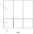
- Figures 1 and 2 show simplified representations of a security barrier (1) according to a first embodiment of the invention, in installed state of the security barrier (1).
- Figures 3 to 5 show parts of this barrier (1) and in figure 6 an alternative embodiment of a part of the security barrier (1) is shown. Of course other embodiments are possible.
- the security barrier (1) of figures 1 and 2 comprise one bottom panel (3), three front panels (2), three side panels (5), three reinforcement panels (4) and three strengthening panels (6). All these panels (2, 3, 4, 5, 6) are mesh panels. Those panels (2, 3, 4, 5, 6) are represented as a white surface. The meshes would make the figures unclear. Also not all panels (2, 3, 4, 5, 6) are indicated with their number for clarity reasons.
- each front panel (2) is connected at an angle of 90° to the bottom panel (3), one or two said side panels (5) and a said strengthening panel (6). Further the bottom panel (3) is connected at an angle of 90° to the three side panels (5) and the three reinforcement panels (4). Each strengthening panel (6) is further connected at an angle of 90° to one or two side panels (5) an to a said reinforcement panel (4).
- Each reinforcement panel (4) is connected parallel to a said front panel (2) such that it covers a bottom part of the respective front panel (2), that is adjacent to the connection between the bottom part (2) and the respective front panel (2), in order to double the bottom part of the said front panel (2).
- the unconnected edges of the side panels (5) are each reinforced with a U-shaped profile (8).
- the strengthening panel (6) extends substantially parallel to the bottom panel (3).
- the front panels (2), the bottom panel (3), the strengthening panels (6) and the reinforcement panels (4) have rectangular shapes and the side panels (5) have a pentagonal shape, wherein the upper part of each side panel (5) has a right-angled triangular shape and is located above the strengthening panels (6) and in which the lower part of each side panel (5) has a rectangular shape and is located below the strengthening panels (6).
- the security barrier (1) comprises two containers which are confined on the bottom by the bottom panel (3), on its sides by the lower parts of two said side panels (5), on the top by a said strengthening panel (6) and on the front by a said reinforcement panel (4), wherein the back of the container is open such that the container is accessible from the back.
- the security barrier (1) can have a fourth side panel (not shown), connected to the front panel (2) and to the strengthening panel (6) and the reinforcement panel (4) which are only connected to one side panel (5) in figures 1 and 2 , such that the security barrier (1) has three containers.
- a security barrier can be composed of several security barriers (1), as shown in figures 1 and 2 , such that a longer security barrier is obtained.
- the security barrier (1) as shown in figures 1 and 2 is then a standardized construction module by which a security barrier of the desired length can be easily obtained.
- the security barrier (1) shown in figures 1 and 2 , is composed of a first and a second construction unit (7a, 7b).
- the first construction unit (7a) according to the first embodiment of the security barrier (1) is shown in figure 3 .
- An alternative embodiment of the first construction unit (7a) is shown in figure 6 .
- the second construction unit (7b) of the first embodiment of the security barrier (1) is shown in figures 4 and 5 .
- the first construction unit (7a) comprises the three front panels (2) and the three side panels (5). These side panels (5) are pivotally connected to the front panels (2) at the level of their edges with the aid of spirals. As a result, the first construction unit (7a) can adopt a compact configuration wherein the side panels (5) are folded up against the front panels (5). This improves the transportation and storage.
- the front panels (2) are provided with spirals, at the level where the edges of the reinforcement panels (4) are provided to be connected to the front panels (2).
- the side panels (5) are provided with spirals at the level where they are provided to be connected to the strengthening panels (6) and the bottom panel (3).
- the first construction unit (7a) as shown in figure 6 is similar, but it only comprises two front panels (2).
- the second construction unit (7b) as shown in figures 4 and 5 comprises the bottom panel (3), the three reinforcement panels (4) and the three strengthening panels (6). These strengthening panels (6) are pivotally connected to the reinforcement panels (4) at the level of their edges with the aid of spirals, and the reinforcement panels (4) are connected to the bottom panel (3) at the level of their edges with the aid of spirals. As a result, the second construction unit (7b) can adopt a compact configuration where the strengthening panels (6) are folded up against the reinforcement panels (4) and the reinforcement panels (4) are folded up against the bottom panel (3). This improves the transportation and storage. Also the other edges of each reinforcement panel (4) and each strengthening panel (6) and also the bottom panel (3), are provided with spirals to connect them to the first construction unit (7a).
- the security barrier (1) can adopt at least two configurations, a first configuration being a compact configuration wherein the first and the second construction units (7a, 7b) are separated from each other and each folded and a second configuration, in installed state of the security barrier (1), wherein the first and the second construction units (7a, 7b) are connected.
- the security barrier (1) is delivered in its first configuration. Then each construction unit (7a, 7b) is unfolded. Then the first construction unit (7a) and the second construction unit (7b) are placed against each other such that the reinforcement panels (4) lean against the bottom parts of the front panels (2) and such that the front panels (2), bottom panel (3) and side panels (5) also take the right configuration and the spirals of the first connection unit (7a) engage with respective spirals of the second construction unit (7b). Rods are fitted through the engaged spirals as such to firmly connect the first construction unit (7a) to the second construction unit (7b).
- the strengthening panels (6) are connected to the side panels (5) by engaging spirals connected to the strengthening panels (6) with spirals connected to the side panels (5) and putting a rod into the said engaged spirals, weights are placed on the bottom panel (3) as such to fill the containers and strengthen the security barrier (1).
- the strengthening panels (6) are then connected to the side panels (5).
- the bottom panels (3), the reinforcement panels (4) and the lower parts of the side panels (5) are further covered with a UV-resistant material. This protects the weights placed upon the bottom panel (3) from UV-light and it also makes sure that a person, standing in front of the security barrier (1), cannot see the weight.
Landscapes
- Engineering & Computer Science (AREA)
- Architecture (AREA)
- Civil Engineering (AREA)
- Structural Engineering (AREA)
- Refuge Islands, Traffic Blockers, Or Guard Fence (AREA)
Claims (15)
- Sicherheitsbarriere (1), umfassend- eine vordere Tafel (2) und;- eine untere Tafel (3);wobei im installierten Zustand der Sicherheitsbarriere (1) die untere Tafel (3) in einem Winkel mit der vorderen Tafel (2) verbunden ist, wobei die Sicherheitsbarriere (1) eine Verstärkungstafel (4) umfasst, die im installierten Zustand der Sicherheitsbarriere (1) zumindest einen Teil der vorderen Tafel (2) bedeckt, um zumindest den Teil der vorderen Tafel (2) zu doppeln, dadurch gekennzeichnet, dass die Sicherheitsbarriere (1) Seitentafeln (5) umfasst, die im installierten Zustand der Sicherheitsbarriere (1) in einem Winkel mit der vorderen Tafel (2) verbunden sind und in einem Winkel mit der unteren Tafel (3) verbunden sind, und wobei in dem installierten Zustand der Sicherheitsbarriere (1) die Sicherheitsbarriere (1) zumindest einen Behälter umfasst, der am Boden durch die untere Tafel (3), an seinen Seiten durch zwei der Seitentafeln (5) und an der Vorderseite durch die Verstärkungstafel (4) begrenzt wird, wobei die Rückseite des Behälters offen ist, so dass der Behälter von der Rückseite her zugänglich ist.
- Sicherheitsbarriere (1) nach Anspruch 1, dadurch gekennzeichnet, dass die Verstärkungstafel (4) mit der vorderen Tafel (2) verbunden ist.
- Sicherheitsbarriere (1) nach Anspruch 1 oder 2, dadurch gekennzeichnet, dass im installierten Zustand der Sicherheitsbarriere (1) die Verstärkungstafel (4) zumindest die vordere Tafel (2) benachbart zu der Verbindung der vorderen Tafel (2) mit der unteren Tafel (3) abdeckt.
- Sicherheitsbarriere (1) nach Anspruch 3, dadurch gekennzeichnet, dass im installierten Zustand der Sicherheitsbarriere (1) die Verstärkungstafel (4) mit der unteren Tafel (3) verbunden ist.
- Sicherheitsbarriere (1) nach einem der vorhergehenden Ansprüche, dadurch gekennzeichnet, dass die Sicherheitsbarriere (1) aus mindestens zwei Baueinheiten (7a, 7b) besteht, wobei eine erste Baueinheit (7a) der zumindest zwei Baueinheiten (7a, 7b) die vordere Tafel (2) umfasst, und wobei eine zweite Baueinheit (7b) der zumindest zwei Baueinheiten (7a, 7b) die untere Tafel (3) und die Verstärkungstafel (4) umfasst, wobei die Sicherheitsbarriere (1) zumindest zwei Konfigurationen einnehmen kann, wobei eine erste Konfiguration eine kompakte Konfiguration ist, in der die erste und die zweite Baueinheit (7a, 7b) voneinander getrennt sind, und eine zweite Konfiguration im installierten Zustand der Sicherheitsbarriere (1) vorliegt, wobei die erste und die zweite Baueinheit (7a, 7b) verbunden sind.
- Sicherheitsbarriere (1) nach Anspruch 5, dadurch gekennzeichnet, dass die Verstärkungstafel (4) schwenkbar mit der unteren Tafel (3) verbunden ist, und wobei die zweite Baueinheit (7b) in der ersten Konfiguration eingeklappt ist.
- Sicherheitsbarriere (1) nach Anspruch 5 oder 6, dadurch gekennzeichnet, dass die erste Baueinheit (7a) zumindest die zwei Seitentafeln (5) umfasst, die schwenkbar mit der vorderen Tafel (2) der ersten Baueinheit (7a) verbunden sind.
- Sicherheitsbarriere (1) nach einem der vorhergehenden Ansprüche, dadurch gekennzeichnet, dass die Sicherheitsbarriere (1) eine Versteifungstafel (6) umfasst, die im installierten Zustand der Sicherheitsbarriere (1) mit der vorderen Tafel (2) und den zwei aufeinanderfolgenden Seitentafeln (5) in einem bestimmten Abstand von der unteren Tafel (3) verbunden ist.
- Sicherheitsbarriere (1) nach Anspruch 8, dadurch gekennzeichnet, dass die Versteifungstafel (6) sich im installierten Zustand der Sicherheitsbarriere (1) im Wesentlichen parallel zu der unteren Tafel (3) erstreckt.
- Verfahren zur Installation einer Sicherheitsbarriere (1) auf dem Boden, wobei eine vordere Tafel (2) und eine untere Tafel (3) vorgesehen werden, wobei die vordere Tafel (2) aufgerichtet wird und die untere Tafel (3) auf dem Boden platziert wird, wobei eine Verstärkungstafel (4) vorgesehen und zumindest ein Teil der vorderen Tafel (2) durch die Verstärkungstafel (4) abgedeckt und gedoppelt wird, dadurch gekennzeichnet, dass eine erste Baueinheit (7a) umfassend die vordere Tafel (2) und eine zweite Baueinheit (7b) umfassend die untere Tafel (3) sowie die Verstärkungstafel (4) vorgesehen werden, wobei die erste und die zweite Baueinheit (7a, 7b) miteinander durch Verbinden der unteren Tafel (3) mit der vorderen Tafel (2) und Verbinden der Verstärkungstafel (4) im Wesentlichen parallel zu der vorderen Tafel (2) verbunden werden, dass die erste Baueinheit (7a) mit zumindest zwei Seitentafeln (5) versehen ist, wobei während der Verbindung der ersten und der zweiten Baueinheit (7a, 7b) die Seitentafeln (5) mit der unteren Tafel (3) und der Verstärkungstafel (4) verbunden werden, und dass während der Verbindung der ersten und zweiten Baueinheit (7a, 7b) ein Behälter gebildet wird, und dass der Behälter befüllt wird.
- Verfahren nach Anspruch 10, dadurch gekennzeichnet, dass die zweite Baueinheit (7b) in einer ersten Stellung bereitgestellt wird, in welcher die untere Tafel (3) und die Verstärkungstafel (4) schwenkbar miteinander verbunden und eingeklappt sind, und dass die zweite Baueinheit (7b) aufgeklappt wird, bevor sie mit der ersten Baueinheit (7a) verbunden wird.
- Verfahren nach Anspruch 10 oder 11, dadurch gekennzeichnet, dass die erste Baueinheit (7a) in einer ersten Stellung bereitgestellt wird, in welcher die Seitentafeln (5) schwenkbar mit der vorderen Tafel (2) verbunden und eingeklappt sind, und dass die erste Baueinheit (7a) aufgeklappt wird, bevor sie mit der zweiten Baueinheit (7b) verbunden wird.
- Verfahren nach einem der Ansprüche 10 bis 12, dadurch gekennzeichnet, dass die zweite Baueinheit (7b) mit einer Versteifungstafel (6) versehen wird, die schwenkbar mit der Verstärkungstafel (4) verbunden wird, wobei während der Verbindung der ersten und der zweiten Baueinheit (7a, 7b) die Versteifungstafel (6) mit den Seitentafeln (5) und der vorderen Tafel (2) verbunden wird.
- Verfahren nach einem der Ansprüche 10 bis 13, dadurch gekennzeichnet, dass der Behälter befüllt wird, bevor die Versteifungstafel (6) mit den Seitentafeln (5) verbunden wird.
- Verfahren nach einem der Ansprüche 10 bis 14, wobei die Sicherheitsbarriere (1) eine Sicherheitsbarriere (1) nach einem der Ansprüche 1 bis 9 ist.
Applications Claiming Priority (1)
| Application Number | Priority Date | Filing Date | Title |
|---|---|---|---|
| PCT/IB2015/054576 WO2016203292A1 (en) | 2015-06-17 | 2015-06-17 | Security barrier and method of installing a security barrier |
Publications (2)
| Publication Number | Publication Date |
|---|---|
| EP3310967A1 EP3310967A1 (de) | 2018-04-25 |
| EP3310967B1 true EP3310967B1 (de) | 2019-08-14 |
Family
ID=53502716
Family Applications (1)
| Application Number | Title | Priority Date | Filing Date |
|---|---|---|---|
| EP15733918.5A Active EP3310967B1 (de) | 2015-06-17 | 2015-06-17 | Sicherheitsbarriere und verfahren zur herstellung einer sicherheitsbarriere |
Country Status (6)
| Country | Link |
|---|---|
| US (1) | US20180179782A1 (de) |
| EP (1) | EP3310967B1 (de) |
| BE (1) | BE1023444B1 (de) |
| RU (1) | RU2681142C1 (de) |
| WO (1) | WO2016203292A1 (de) |
| ZA (1) | ZA201708171B (de) |
Families Citing this family (2)
| Publication number | Priority date | Publication date | Assignee | Title |
|---|---|---|---|---|
| RU2747069C1 (ru) * | 2020-10-07 | 2021-04-23 | Управляющая компания общество с ограниченной ответственностью | Ограждение головки балансира станка-качалки |
| GB2621326A (en) * | 2022-08-04 | 2024-02-14 | Praesidiad Holding Bvba | Fence panel |
Family Cites Families (6)
| Publication number | Priority date | Publication date | Assignee | Title |
|---|---|---|---|---|
| US4526347A (en) * | 1981-06-09 | 1985-07-02 | Institute For Industrial Research And Standards | Fence assembly |
| US7494112B2 (en) * | 2005-04-25 | 2009-02-24 | Jeffrey Earl Fromm | Rapid deployment barrier and method of using the same |
| US20090230373A1 (en) | 2006-08-15 | 2009-09-17 | Hesco Bastion Limited | Security barrier |
| SE531421C2 (sv) * | 2007-06-08 | 2009-03-31 | Feros Ab | Anordning avsedd att användas som en avgränsning mellan två områden |
| BE1022107B1 (nl) * | 2013-02-05 | 2016-02-16 | Betafence Holding Nv | Afrastering en werkwijze om een dergelijke afrastering te installeren |
| RU149038U1 (ru) * | 2014-08-28 | 2014-12-20 | Сергей Иванович Мазенков | Модуль ограждения и ограждение на его основе |
-
2015
- 2015-06-17 EP EP15733918.5A patent/EP3310967B1/de active Active
- 2015-06-17 WO PCT/IB2015/054576 patent/WO2016203292A1/en not_active Ceased
- 2015-06-17 US US15/737,671 patent/US20180179782A1/en not_active Abandoned
- 2015-06-17 RU RU2018101445A patent/RU2681142C1/ru active
-
2016
- 2016-04-22 BE BE2016/5277A patent/BE1023444B1/nl not_active IP Right Cessation
-
2017
- 2017-11-30 ZA ZA2017/08171A patent/ZA201708171B/en unknown
Non-Patent Citations (1)
| Title |
|---|
| None * |
Also Published As
| Publication number | Publication date |
|---|---|
| BE1023444A1 (nl) | 2017-03-21 |
| RU2681142C1 (ru) | 2019-03-04 |
| WO2016203292A1 (en) | 2016-12-22 |
| ZA201708171B (en) | 2019-06-26 |
| US20180179782A1 (en) | 2018-06-28 |
| EP3310967A1 (de) | 2018-04-25 |
| BE1023444B1 (nl) | 2017-03-21 |
Similar Documents
| Publication | Publication Date | Title |
|---|---|---|
| US9435088B2 (en) | Structural tube based vehicle crash fence | |
| US10738425B2 (en) | Security barrier | |
| US9670631B2 (en) | Vehicle and personal barrier for construction site | |
| AU2018366709B2 (en) | Erectable barrier's basic unit and an erectable barrier comprising the same | |
| US9074337B2 (en) | Gabion system | |
| EP3684979B1 (de) | Zaun mit zaunmodulen | |
| US20090250675A1 (en) | Vehicle Barrier | |
| US9481970B2 (en) | Gabion | |
| US20070163189A1 (en) | Explosion-absorbing panels and wall structures | |
| EP2271806A2 (de) | Fahrzeugsperre | |
| US9335140B2 (en) | Architectural mesh blast screen system | |
| US20180179782A1 (en) | Security barrier and method of installing a security barrier | |
| AU2009290631A1 (en) | Sight screen | |
| WO2011108982A1 (en) | Storage cage intended for temporary protection of domestic animal or other objects | |
| US10030409B2 (en) | Fence and method of installing a fence | |
| WO2012107745A1 (en) | Security barrier | |
| JP2017002482A (ja) | 落石土砂防護柵付き擁壁 | |
| KR102754058B1 (ko) | 가드레일 보강 및 도약방지 보조레일 | |
| KR100787593B1 (ko) | 격자망 합성 강재틀 옹벽구조 | |
| EA043733B1 (ru) | Складной защитный барьер | |
| ES1091755U (es) | Pantalla acústica protectora con elementos vegetales | |
| HK1134330B (zh) | 安全栅栏 |
Legal Events
| Date | Code | Title | Description |
|---|---|---|---|
| STAA | Information on the status of an ep patent application or granted ep patent |
Free format text: STATUS: THE INTERNATIONAL PUBLICATION HAS BEEN MADE |
|
| PUAI | Public reference made under article 153(3) epc to a published international application that has entered the european phase |
Free format text: ORIGINAL CODE: 0009012 |
|
| STAA | Information on the status of an ep patent application or granted ep patent |
Free format text: STATUS: REQUEST FOR EXAMINATION WAS MADE |
|
| 17P | Request for examination filed |
Effective date: 20171227 |
|
| AK | Designated contracting states |
Kind code of ref document: A1 Designated state(s): AL AT BE BG CH CY CZ DE DK EE ES FI FR GB GR HR HU IE IS IT LI LT LU LV MC MK MT NL NO PL PT RO RS SE SI SK SM TR |
|
| AX | Request for extension of the european patent |
Extension state: BA ME |
|
| DAV | Request for validation of the european patent (deleted) | ||
| DAX | Request for extension of the european patent (deleted) | ||
| GRAP | Despatch of communication of intention to grant a patent |
Free format text: ORIGINAL CODE: EPIDOSNIGR1 |
|
| STAA | Information on the status of an ep patent application or granted ep patent |
Free format text: STATUS: GRANT OF PATENT IS INTENDED |
|
| RAP1 | Party data changed (applicant data changed or rights of an application transferred) |
Owner name: GUARDIAR EUROPE |
|
| INTG | Intention to grant announced |
Effective date: 20190319 |
|
| GRAS | Grant fee paid |
Free format text: ORIGINAL CODE: EPIDOSNIGR3 |
|
| GRAA | (expected) grant |
Free format text: ORIGINAL CODE: 0009210 |
|
| STAA | Information on the status of an ep patent application or granted ep patent |
Free format text: STATUS: THE PATENT HAS BEEN GRANTED |
|
| AK | Designated contracting states |
Kind code of ref document: B1 Designated state(s): AL AT BE BG CH CY CZ DE DK EE ES FI FR GB GR HR HU IE IS IT LI LT LU LV MC MK MT NL NO PL PT RO RS SE SI SK SM TR |
|
| REG | Reference to a national code |
Ref country code: GB Ref legal event code: FG4D |
|
| REG | Reference to a national code |
Ref country code: CH Ref legal event code: EP Ref country code: AT Ref legal event code: REF Ref document number: 1167183 Country of ref document: AT Kind code of ref document: T Effective date: 20190815 |
|
| REG | Reference to a national code |
Ref country code: IE Ref legal event code: FG4D |
|
| REG | Reference to a national code |
Ref country code: DE Ref legal event code: R096 Ref document number: 602015035824 Country of ref document: DE |
|
| RAP2 | Party data changed (patent owner data changed or rights of a patent transferred) |
Owner name: GUARDIAR EUROPE BVBA |
|
| REG | Reference to a national code |
Ref country code: NL Ref legal event code: MP Effective date: 20190814 |
|
| REG | Reference to a national code |
Ref country code: LT Ref legal event code: MG4D |
|
| PG25 | Lapsed in a contracting state [announced via postgrant information from national office to epo] |
Ref country code: HR Free format text: LAPSE BECAUSE OF FAILURE TO SUBMIT A TRANSLATION OF THE DESCRIPTION OR TO PAY THE FEE WITHIN THE PRESCRIBED TIME-LIMIT Effective date: 20190814 Ref country code: LT Free format text: LAPSE BECAUSE OF FAILURE TO SUBMIT A TRANSLATION OF THE DESCRIPTION OR TO PAY THE FEE WITHIN THE PRESCRIBED TIME-LIMIT Effective date: 20190814 Ref country code: NL Free format text: LAPSE BECAUSE OF FAILURE TO SUBMIT A TRANSLATION OF THE DESCRIPTION OR TO PAY THE FEE WITHIN THE PRESCRIBED TIME-LIMIT Effective date: 20190814 Ref country code: BG Free format text: LAPSE BECAUSE OF FAILURE TO SUBMIT A TRANSLATION OF THE DESCRIPTION OR TO PAY THE FEE WITHIN THE PRESCRIBED TIME-LIMIT Effective date: 20191114 Ref country code: PT Free format text: LAPSE BECAUSE OF FAILURE TO SUBMIT A TRANSLATION OF THE DESCRIPTION OR TO PAY THE FEE WITHIN THE PRESCRIBED TIME-LIMIT Effective date: 20191216 Ref country code: NO Free format text: LAPSE BECAUSE OF FAILURE TO SUBMIT A TRANSLATION OF THE DESCRIPTION OR TO PAY THE FEE WITHIN THE PRESCRIBED TIME-LIMIT Effective date: 20191114 Ref country code: FI Free format text: LAPSE BECAUSE OF FAILURE TO SUBMIT A TRANSLATION OF THE DESCRIPTION OR TO PAY THE FEE WITHIN THE PRESCRIBED TIME-LIMIT Effective date: 20190814 Ref country code: SE Free format text: LAPSE BECAUSE OF FAILURE TO SUBMIT A TRANSLATION OF THE DESCRIPTION OR TO PAY THE FEE WITHIN THE PRESCRIBED TIME-LIMIT Effective date: 20190814 |
|
| REG | Reference to a national code |
Ref country code: AT Ref legal event code: MK05 Ref document number: 1167183 Country of ref document: AT Kind code of ref document: T Effective date: 20190814 |
|
| PG25 | Lapsed in a contracting state [announced via postgrant information from national office to epo] |
Ref country code: RS Free format text: LAPSE BECAUSE OF FAILURE TO SUBMIT A TRANSLATION OF THE DESCRIPTION OR TO PAY THE FEE WITHIN THE PRESCRIBED TIME-LIMIT Effective date: 20190814 Ref country code: GR Free format text: LAPSE BECAUSE OF FAILURE TO SUBMIT A TRANSLATION OF THE DESCRIPTION OR TO PAY THE FEE WITHIN THE PRESCRIBED TIME-LIMIT Effective date: 20191115 Ref country code: IS Free format text: LAPSE BECAUSE OF FAILURE TO SUBMIT A TRANSLATION OF THE DESCRIPTION OR TO PAY THE FEE WITHIN THE PRESCRIBED TIME-LIMIT Effective date: 20191214 Ref country code: AL Free format text: LAPSE BECAUSE OF FAILURE TO SUBMIT A TRANSLATION OF THE DESCRIPTION OR TO PAY THE FEE WITHIN THE PRESCRIBED TIME-LIMIT Effective date: 20190814 Ref country code: ES Free format text: LAPSE BECAUSE OF FAILURE TO SUBMIT A TRANSLATION OF THE DESCRIPTION OR TO PAY THE FEE WITHIN THE PRESCRIBED TIME-LIMIT Effective date: 20190814 Ref country code: LV Free format text: LAPSE BECAUSE OF FAILURE TO SUBMIT A TRANSLATION OF THE DESCRIPTION OR TO PAY THE FEE WITHIN THE PRESCRIBED TIME-LIMIT Effective date: 20190814 |
|
| PG25 | Lapsed in a contracting state [announced via postgrant information from national office to epo] |
Ref country code: TR Free format text: LAPSE BECAUSE OF FAILURE TO SUBMIT A TRANSLATION OF THE DESCRIPTION OR TO PAY THE FEE WITHIN THE PRESCRIBED TIME-LIMIT Effective date: 20190814 |
|
| PG25 | Lapsed in a contracting state [announced via postgrant information from national office to epo] |
Ref country code: AT Free format text: LAPSE BECAUSE OF FAILURE TO SUBMIT A TRANSLATION OF THE DESCRIPTION OR TO PAY THE FEE WITHIN THE PRESCRIBED TIME-LIMIT Effective date: 20190814 Ref country code: EE Free format text: LAPSE BECAUSE OF FAILURE TO SUBMIT A TRANSLATION OF THE DESCRIPTION OR TO PAY THE FEE WITHIN THE PRESCRIBED TIME-LIMIT Effective date: 20190814 Ref country code: DK Free format text: LAPSE BECAUSE OF FAILURE TO SUBMIT A TRANSLATION OF THE DESCRIPTION OR TO PAY THE FEE WITHIN THE PRESCRIBED TIME-LIMIT Effective date: 20190814 Ref country code: RO Free format text: LAPSE BECAUSE OF FAILURE TO SUBMIT A TRANSLATION OF THE DESCRIPTION OR TO PAY THE FEE WITHIN THE PRESCRIBED TIME-LIMIT Effective date: 20190814 Ref country code: PL Free format text: LAPSE BECAUSE OF FAILURE TO SUBMIT A TRANSLATION OF THE DESCRIPTION OR TO PAY THE FEE WITHIN THE PRESCRIBED TIME-LIMIT Effective date: 20190814 |
|
| PG25 | Lapsed in a contracting state [announced via postgrant information from national office to epo] |
Ref country code: SK Free format text: LAPSE BECAUSE OF FAILURE TO SUBMIT A TRANSLATION OF THE DESCRIPTION OR TO PAY THE FEE WITHIN THE PRESCRIBED TIME-LIMIT Effective date: 20190814 Ref country code: CZ Free format text: LAPSE BECAUSE OF FAILURE TO SUBMIT A TRANSLATION OF THE DESCRIPTION OR TO PAY THE FEE WITHIN THE PRESCRIBED TIME-LIMIT Effective date: 20190814 Ref country code: IS Free format text: LAPSE BECAUSE OF FAILURE TO SUBMIT A TRANSLATION OF THE DESCRIPTION OR TO PAY THE FEE WITHIN THE PRESCRIBED TIME-LIMIT Effective date: 20200224 Ref country code: SM Free format text: LAPSE BECAUSE OF FAILURE TO SUBMIT A TRANSLATION OF THE DESCRIPTION OR TO PAY THE FEE WITHIN THE PRESCRIBED TIME-LIMIT Effective date: 20190814 |
|
| REG | Reference to a national code |
Ref country code: DE Ref legal event code: R097 Ref document number: 602015035824 Country of ref document: DE |
|
| PLBE | No opposition filed within time limit |
Free format text: ORIGINAL CODE: 0009261 |
|
| STAA | Information on the status of an ep patent application or granted ep patent |
Free format text: STATUS: NO OPPOSITION FILED WITHIN TIME LIMIT |
|
| PG2D | Information on lapse in contracting state deleted |
Ref country code: IS |
|
| 26N | No opposition filed |
Effective date: 20200603 |
|
| PG25 | Lapsed in a contracting state [announced via postgrant information from national office to epo] |
Ref country code: SI Free format text: LAPSE BECAUSE OF FAILURE TO SUBMIT A TRANSLATION OF THE DESCRIPTION OR TO PAY THE FEE WITHIN THE PRESCRIBED TIME-LIMIT Effective date: 20190814 |
|
| PG25 | Lapsed in a contracting state [announced via postgrant information from national office to epo] |
Ref country code: MC Free format text: LAPSE BECAUSE OF FAILURE TO SUBMIT A TRANSLATION OF THE DESCRIPTION OR TO PAY THE FEE WITHIN THE PRESCRIBED TIME-LIMIT Effective date: 20190814 |
|
| REG | Reference to a national code |
Ref country code: CH Ref legal event code: PL |
|
| PG25 | Lapsed in a contracting state [announced via postgrant information from national office to epo] |
Ref country code: LU Free format text: LAPSE BECAUSE OF NON-PAYMENT OF DUE FEES Effective date: 20200617 |
|
| PG25 | Lapsed in a contracting state [announced via postgrant information from national office to epo] |
Ref country code: LI Free format text: LAPSE BECAUSE OF NON-PAYMENT OF DUE FEES Effective date: 20200630 Ref country code: CH Free format text: LAPSE BECAUSE OF NON-PAYMENT OF DUE FEES Effective date: 20200630 |
|
| PGFP | Annual fee paid to national office [announced via postgrant information from national office to epo] |
Ref country code: FR Payment date: 20210615 Year of fee payment: 7 Ref country code: DE Payment date: 20210618 Year of fee payment: 7 |
|
| PGFP | Annual fee paid to national office [announced via postgrant information from national office to epo] |
Ref country code: BE Payment date: 20210624 Year of fee payment: 7 Ref country code: IE Payment date: 20210617 Year of fee payment: 7 |
|
| PG25 | Lapsed in a contracting state [announced via postgrant information from national office to epo] |
Ref country code: MT Free format text: LAPSE BECAUSE OF FAILURE TO SUBMIT A TRANSLATION OF THE DESCRIPTION OR TO PAY THE FEE WITHIN THE PRESCRIBED TIME-LIMIT Effective date: 20190814 Ref country code: CY Free format text: LAPSE BECAUSE OF FAILURE TO SUBMIT A TRANSLATION OF THE DESCRIPTION OR TO PAY THE FEE WITHIN THE PRESCRIBED TIME-LIMIT Effective date: 20190814 |
|
| PG25 | Lapsed in a contracting state [announced via postgrant information from national office to epo] |
Ref country code: MK Free format text: LAPSE BECAUSE OF FAILURE TO SUBMIT A TRANSLATION OF THE DESCRIPTION OR TO PAY THE FEE WITHIN THE PRESCRIBED TIME-LIMIT Effective date: 20190814 |
|
| REG | Reference to a national code |
Ref country code: DE Ref legal event code: R119 Ref document number: 602015035824 Country of ref document: DE |
|
| REG | Reference to a national code |
Ref country code: BE Ref legal event code: MM Effective date: 20220630 |
|
| PG25 | Lapsed in a contracting state [announced via postgrant information from national office to epo] |
Ref country code: IE Free format text: LAPSE BECAUSE OF NON-PAYMENT OF DUE FEES Effective date: 20220617 Ref country code: FR Free format text: LAPSE BECAUSE OF NON-PAYMENT OF DUE FEES Effective date: 20220630 |
|
| PG25 | Lapsed in a contracting state [announced via postgrant information from national office to epo] |
Ref country code: DE Free format text: LAPSE BECAUSE OF NON-PAYMENT OF DUE FEES Effective date: 20230103 Ref country code: BE Free format text: LAPSE BECAUSE OF NON-PAYMENT OF DUE FEES Effective date: 20220630 |
|
| P01 | Opt-out of the competence of the unified patent court (upc) registered |
Effective date: 20230526 |
|
| PGFP | Annual fee paid to national office [announced via postgrant information from national office to epo] |
Ref country code: GB Payment date: 20250618 Year of fee payment: 11 |
|
| PGFP | Annual fee paid to national office [announced via postgrant information from national office to epo] |
Ref country code: IT Payment date: 20250618 Year of fee payment: 11 |