EP3310653B1 - Fluid flow control for an aerofoil - Google Patents
Fluid flow control for an aerofoil Download PDFInfo
- Publication number
- EP3310653B1 EP3310653B1 EP16750993.4A EP16750993A EP3310653B1 EP 3310653 B1 EP3310653 B1 EP 3310653B1 EP 16750993 A EP16750993 A EP 16750993A EP 3310653 B1 EP3310653 B1 EP 3310653B1
- Authority
- EP
- European Patent Office
- Prior art keywords
- duct
- fluid
- wing
- region
- opening
- Prior art date
- Legal status (The legal status is an assumption and is not a legal conclusion. Google has not performed a legal analysis and makes no representation as to the accuracy of the status listed.)
- Active
Links
- 239000012530 fluid Substances 0.000 title claims description 110
- 230000015572 biosynthetic process Effects 0.000 claims description 19
- 230000000694 effects Effects 0.000 description 10
- 238000004458 analytical method Methods 0.000 description 6
- 239000000446 fuel Substances 0.000 description 5
- 230000003993 interaction Effects 0.000 description 5
- 238000005452 bending Methods 0.000 description 4
- 238000009826 distribution Methods 0.000 description 4
- 238000000034 method Methods 0.000 description 4
- 230000002829 reductive effect Effects 0.000 description 4
- 238000005728 strengthening Methods 0.000 description 4
- 230000007423 decrease Effects 0.000 description 3
- 230000006872 improvement Effects 0.000 description 3
- 230000009467 reduction Effects 0.000 description 3
- 230000002411 adverse Effects 0.000 description 2
- 238000007664 blowing Methods 0.000 description 2
- 238000004364 calculation method Methods 0.000 description 2
- 230000003247 decreasing effect Effects 0.000 description 2
- 238000011161 development Methods 0.000 description 2
- 238000010586 diagram Methods 0.000 description 2
- 230000013011 mating Effects 0.000 description 2
- 238000005096 rolling process Methods 0.000 description 2
- 235000001674 Agaricus brunnescens Nutrition 0.000 description 1
- 101100042630 Caenorhabditis elegans sin-3 gene Proteins 0.000 description 1
- 230000001174 ascending effect Effects 0.000 description 1
- 230000008859 change Effects 0.000 description 1
- 230000009194 climbing Effects 0.000 description 1
- 238000004891 communication Methods 0.000 description 1
- 230000000254 damaging effect Effects 0.000 description 1
- 238000013461 design Methods 0.000 description 1
- 239000011888 foil Substances 0.000 description 1
- 238000011065 in-situ storage Methods 0.000 description 1
- 230000002401 inhibitory effect Effects 0.000 description 1
- 238000002955 isolation Methods 0.000 description 1
- 238000004519 manufacturing process Methods 0.000 description 1
- 230000005012 migration Effects 0.000 description 1
- 238000013508 migration Methods 0.000 description 1
- 230000000116 mitigating effect Effects 0.000 description 1
- 238000012986 modification Methods 0.000 description 1
- 230000004048 modification Effects 0.000 description 1
- 244000045947 parasite Species 0.000 description 1
- 238000000926 separation method Methods 0.000 description 1
- 238000004088 simulation Methods 0.000 description 1
- 230000008719 thickening Effects 0.000 description 1
- 230000007704 transition Effects 0.000 description 1
Images


Classifications
-
- B—PERFORMING OPERATIONS; TRANSPORTING
- B64—AIRCRAFT; AVIATION; COSMONAUTICS
- B64C—AEROPLANES; HELICOPTERS
- B64C23/00—Influencing air flow over aircraft surfaces, not otherwise provided for
- B64C23/06—Influencing air flow over aircraft surfaces, not otherwise provided for by generating vortices
- B64C23/065—Influencing air flow over aircraft surfaces, not otherwise provided for by generating vortices at the wing tips
- B64C23/069—Influencing air flow over aircraft surfaces, not otherwise provided for by generating vortices at the wing tips using one or more wing tip airfoil devices, e.g. winglets, splines, wing tip fences or raked wingtips
-
- B—PERFORMING OPERATIONS; TRANSPORTING
- B64—AIRCRAFT; AVIATION; COSMONAUTICS
- B64C—AEROPLANES; HELICOPTERS
- B64C21/00—Influencing air flow over aircraft surfaces by affecting boundary layer flow
- B64C21/02—Influencing air flow over aircraft surfaces by affecting boundary layer flow by use of slot, ducts, porous areas or the like
-
- Y—GENERAL TAGGING OF NEW TECHNOLOGICAL DEVELOPMENTS; GENERAL TAGGING OF CROSS-SECTIONAL TECHNOLOGIES SPANNING OVER SEVERAL SECTIONS OF THE IPC; TECHNICAL SUBJECTS COVERED BY FORMER USPC CROSS-REFERENCE ART COLLECTIONS [XRACs] AND DIGESTS
- Y02—TECHNOLOGIES OR APPLICATIONS FOR MITIGATION OR ADAPTATION AGAINST CLIMATE CHANGE
- Y02T—CLIMATE CHANGE MITIGATION TECHNOLOGIES RELATED TO TRANSPORTATION
- Y02T50/00—Aeronautics or air transport
- Y02T50/10—Drag reduction
Definitions
- This invention relates to a device for influencing the fluid flow over an aerofoil, and in particular to influencing the wake flow of an aerofoil.
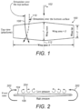
- Figure 1 shows the wings 100 of an aircraft in plan view.
- the wings are shown with a wingspan b, a wing area S, a root chord length C r and a tip chord length Ct and are disposed either side of a fuselage (indicated here by the centreline 112).
- An oncoming fluid with a free stream velocity V ⁇ (relative to the wings) is shown at 102.
- the wings have an upper surface 104 and a lower surface 106.
- the fluid flow over the upper and lower surfaces of the wing when the wing is at an appropriate angle of attack to the flow, produces a relatively low pressure region over the upper surface and a relatively high pressure region over the lower surface to thereby generate lift.
- the upper surface may therefore be referred to as a lower, or low, pressure surface and the lower surface a higher, or high, pressure surface.
- the streamlines over the lower surface diverge from the fuselage in the outboard direction whilst the streamlines over the upper surface converge to the fuselage in the inboard direction.
- vortices are produced.
- the resultant vortex field extends across the trailing edge of the wing out to the wingtips.
- the vortices along the trailing edge may be referred to as bound vortices; that is according to Kutta Joukowsky theorem they circulate the wing as a boundary layer leaving vortices to shed from the trailing-edge of the wing.
- the wingtip vortices are known as trailing vortices and extend downstream from the wingtips.
- the vortices shed from both wings produce a trailing vortex sheet, bound by vortices attached and trailing from the wingtips.
- the vortices of the vortex sheet have less energy (i.e. their cores are at relatively lower pressure) than those at the wingtips and as a consequence are drawn towards or into the wingtip vortex core thus strengthening the wake turbulence generated.
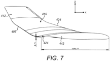
- the vortices shed from the wing are illustrated in figure 2 , which shows the wing in front view.
- the vortices shed from the wingtips are denoted at 202 and the lower energy vortex sheet denoted at 204.
- the effect of vortices shed from the wing trailing edge and wingtip vortices is to induce a downward component of velocity at and behind the wing.
- This downward component is called downwash.
- the magnitude of the downwash at any section along the span is equal to the sum of the effects of all the trailing vortices along the entire span.
- the effect of the downwash is to change the relative direction of the airstream over the section of the wing, which reduces the angle of attack of the wing.
- the downwash in effect rotates the relative direction of the incoming flow. This rotation of the airflow over the wing causes a corresponding rotation of the lift vector (which is typically perpendicular to the relative direction of the incoming flow) to produce a drag component in the direction of motion.
- This component is called the "Induced Drag", and may be denoted D i .
- blended winglets - airfoil section members extending upwardly from the tips of the wings.
- the purpose of these winglets is to control the flow of air from the high-pressure (lower wing) surface to the lower pressure (upper wing) surface and so reduce the strength of wingtip vortices, and thus the Induced Drag.
- blended winglets may provide some reduction in the induced drag created by the wingtip vortices, it does not eliminate the trailing vortex wake created by the converging/diverging airflows at the wing trailing edge. Further, since such winglets are subject to dynamic and lateral flow forces, the winglet produces tension and/or torsion stresses in the associated wing spar section(s) of the wing. Wings employing winglets therefore often require strengthening to avoid mechanical failure. They may also have additional weight penalties.
- US 2011/0309202 describes a control device for a wing that comprises an airbox assembly connected to an aerofoil wingtip.
- the airbox assembly includes passages that receive air from the lower surface of the aerofoil and accelerate and exhaust air upwardly, outwardly and rearwardly of the aerofoil.
- EP 2604517 describes an airfoil tip vortex mitigation device that includes an intake port on a first surface of an airfoil and an exit port in fluid communication with the intake port and disposed on a second surface of the airfoil where air pressure is less than at the first surface.
- US 5,806,807 describes a vortex attenuating airfoil.
- An air passage extends through the airfoil from an inlet on the high pressure side to an outlet on the low pressure side.
- the outlet is positioned in the outboard area between a deflector and tip of the airfoil.
- US 4,382,569 describes a capture device at the tip of an fluid foil.
- the capture device intercepts a quantity of crossflow fluid which is generated by the difference in pressure on the lower surface relative to the upper surface so that lift-induced drag is reduced.
- a device for influencing the wake flow of an aircraft wing having an inboard root end and an outboard tip end, a high pressure side and a low pressure side and a leading edge and a trailing edge
- the device comprising a body adapted for attachment in the region of the tip of the aircraft wing and having a through-duct with a first opening at a first end of the duct being located on the high pressure side of the wing and a second opening at a second end of the duct being located on the low pressure side of the wing, the duct being configured to, when the wing is exposed to fluid flow, permit an fluid flow through the duct so as to inhibit the flow of fluid around the outboard extremity of the wing and to direct the fluid flow through the duct into a pair of opposing rotating flows of substantially equal magnitude externally of the duct
- the first opening of the duct is formed in part from: (i) an intake surface contoured to entrain oncoming fluid into the duct along an inboard region at relative low pressure
- the present invention also provides an aerofoil comprising a structure for influencing the wake flow of the aerofoil as described above.
- the duct may have a plenum located between the first and second openings, and a first restriction located between the plenum and the first opening.
- the duct may further have a second restriction located between the plenum and the second opening.
- the fluid-arresting structure may be in the shape of an aerofoil nose section. It may define an outboard edge of the first opening.
- the fluid-arresting structure may be a convex portion of the outboard wall of the duct.
- the fluid-arresting structure may at least in part define the first restriction.
- the fluid-arresting structure may be configured to, when the device or aerofoil is exposed to fluid flow, reduce the velocity of fluid entering the duct within an outboard region of the duct to thereby generate the relative high pressure region.
- the fluid-arresting structure may comprise a trip strip in the vicinity of the first opening.
- the region of relative high pressure may cause the airflow through the duct to have a pressure and velocity imbalance between inboard and outboard sides of the duct within the first restriction and the plenum.
- the duct may be configured to have a cross-sectional area profile that causes the region of relative high pressure to adopt an aerofoil shape oriented generally along the longitudinal direction of the duct.
- the duct may be configured so that, when the device or aerofoil is exposed to a fluid flow, the region of relative low pressure along the inboard region of the duct and the increase in duct surface area from the first restriction to the plenum causes the region of relative high pressure to adopt the aerofoil shape.
- the region of relative high pressure may cause part of the airflow through the duct to adopt a first rotational component.
- the region of relative high pressure of aerofoil shape causes part of the airflow through the duct to adopt streamlines that follow said aerofoil shape thereby causing said part of the airflow to adopt the first rotational component.
- the duct may be configured to generate a region of relative low pressure along its inboard wall adjacent to the region of relative high pressure
- the body may comprise an intake surface that extends into an inboard wall of the duct, the intake surface being configured to, when the device or aerofoil is exposed to fluid flow, entrain fluid into the duct via the first opening, the intake surface extending generally in an upwards and outboard direction to encourage a part of the fluid flow through the duct to remain attached to the inboard wall.
- the intake surface may be contoured so as to cause a part of the fluid flow through the duct along its inboard region to adopt a second rotational component opposite in direction to the first rotational component.
- the second restriction may be configured to cause the part of the airflow with the first rotational component to adopt a substantially equal mass flow rate as the part of the airflow with the second rotational component and to direct said parts of the airflow out of the duct via the second opening into the pair of opposing rotating flows.
- the second restriction may be configured to equalise fluid pressure and velocity imbalances between the inboard and outboard regions of the duct.
- the region of relative high pressure may have a fluid velocity less than approximately 60ms -1 when the device or aerofoil is exposed to fluid flow with a velocity between 190ms -1 and 210ms -1 .
- the intake surface leading into the duct opening may be swept relative to a chord line of the body. It may be swept by approximately 5 degrees.
- the body may have a first outer surface that encompasses the first opening and a second outer surface that encompasses the second opening, the first and second outer surfaces being cambered so as to, when exposed to fluid flow, generate a first localised region of low pressure outboard of the first opening on the high pressure side, and a second region of low pressure inboard of the second opening on the low pressure side, whereby the first and second low pressure regions pressure balance the pair of opposing rotating flows.
- the second region of low pressure may be in the vicinity of the tip and operate to re-orientate streamlines thereover to thereby inhibit the creation of vortices from the trailing edge.
- the body may have a leading edge and at least one chord line, the leading edge defining a sweep angle relative to the at least one chord line.
- the sweep angle between the chord line and leading edge may be approximately 24 degrees.
- the centroid of the second opening may be positioned outboard and aft relative to the centroid of the first opening.
- the first opening may be a fluid inlet and the second opening a fluid outlet.
- an aircraft wing having a formation at its tip defining a duct extending through the wing from its underside to its upper side, the duct having an inlet on the underside of the wing and an outlet on the upper side of the wing, a plenum between the inlet and the outlet and a restriction between the inlet and the plenum, the duct being configured so that, when the wing is exposed to a free-stream flow, a flow is developed through the duct, the restriction contributes to the formation of a relatively high pressure region on the outboard side of the duct in the region of the plenum and the majority of the flow leaving the duct by the outlet is constituted as two counter-rotating vortices.
- the inboard surface of the duct may be concave in the region of the restriction and the outboard wall of the duct is convex in the region of the restriction.
- the inboard edge of the inlet may be smoothly curved and extend generally in an upwards and outboard direction, thereby encouraging the attachment of a boundary layer to the inboard wall of the duct.
- the outboard edge of the inlet may comprise an abrupt formation for encouraging a turbulent flow at the outboard region of the entrance to the duct.
- the abrupt formation may be a trip strip extending along the outboard edge of the inlet.
- the duct may be configured such that when the wing is subject to a free-stream flow at a cruising speed of the aircraft the two counter-rotating vortices are of substantially equal energy.
- the duct may be configured such that when the wing is subject to a free-stream flow at a cruising speed of the aircraft the two counter-rotating vortices are directed in such a way as to meet and substantially cancel the angular momentum of their respective flows downstream of the wing.
- the device may form part of the aerofoil (e.g. be integral with the aerofoil) or it may be a standalone component capable of being fitted to existing aerofoils in the region of the aerofoil's tip, i.e. so as to occupy an outboard position of the aerofoil.
- the device comprises a passive fluid-blowing system that inhibits the formation of wingtip vortices and thus reduces induced drag on the aerofoil.
- the fluid-blowing system comprises a body with a duct extending through the body from a first opening positioned on the normally high pressure side of the aerofoil (for an aircraft wing this is the lower surface of the aerofoil) to a second opening positioned on the normally low pressure side of the aerofoil (for an aircraft wing this is the upper surface of the aerofoil).
- a first opening positioned on the normally high pressure side of the aerofoil for an aircraft wing this is the lower surface of the aerofoil
- a second opening positioned on the normally low pressure side of the aerofoil (for an aircraft wing this is the upper surface of the aerofoil).
- the flows extend substantially in the direction of the free stream flow to which the aerofoil is subject.
- the flows rotate in opposite directions to each other.
- the flows are of substantially equal magnitude, or more particularly vorticity magnitude.
- the duct is configured such that these contra-rotating flows are directed so as to interact with each other downstream of the duct.
- the duct is configured that due in part to the substantially equal magnitude and opposite rotation direction of the flows, the interaction of the flows causes their vorticity to at least substantially cancel in the near downstream of the aerofoil. In comparison with normal aerofoils, this cancellation can have the effect of reducing induced drag.
- the body of the device may be shaped to induce the entrainment of fluid in the high pressure region into the inlet of the duct and to prevent the separation of flow within the duct which might otherwise adversely affect the ability of the duct to generate the contra-rotating flows at its outlet.
- the body of the device may as such be swept (i.e. with the centroid of the outlet being aft of the centroid of the inlet with respect to the direction of free stream flow over the aerofoil) and canted (i.e. with the centroid of the outlet being outboard of the centroid of the inlet).
- the figures are described with reference to Cartesian coordinate axes.
- the x-axis extends along the longitudinal extent of the fuselage of the aircraft.
- the y-axis is perpendicular to the x-axis and extends along the general spanwise direction of the aircraft.
- the y-axis need not necessarily be parallel to the wings of the aircraft: the wings may be swept for example.
- the z-axis is orthogonal to both the x and y-axes.
- FIG. 3 shows an aircraft 300.
- the aircraft comprises a fuselage 302 and wings 304 a and 304 b .
- the oncoming fluid flow relative to the aircraft is denoted V ⁇
- Each wing has an upper surface 306 a,b and a lower surface 308 a,b .
- the upper surface is in a region of relative low pressure and the lower surface is in a region of relative high pressure.
- the pressure differential is caused by the flow of the fluid over the wing during normal use of the aircraft (e.g. during flight and at a suitable angle of attack).
- the wings of the aircraft have a root end 310 a,b and a tip end 312 a,b .
- Each wing further comprises a leading edge 314 a,b and a trailing edge 316 a,b .
- the leading edge is the foremost edge of the wing. It is the edge that first comes into contact with the oncoming fluid flow.
- the trailing edge is the rear or aftmost edge of the wing.
- the root end may refer to the end of the wing disposed at or in the vicinity of the fuselage.
- the portion of the wing disposed at the root end may as such be referred to as the root.
- the tip end may refer to the end of the wing furthest or further from the fuselage. It may refer to the region of the wing in which the outer extremity of the wing is disposed.
- the outer extremity of the wing may as such be referred to as the tip of the wing.
- the tip and root of the wing may be the extrema of a range of positions along the general spanwise direction of the aircraft. These positions may be referred to herein as inboard and outboard.
- 'inboard' may refer to positions or locations towards or in the vicinity of the centreline of the aircraft, or towards the root end of the wing.
- 'Inboard' may also be used in a directional sense to define the orientation of a surface or component.
- an inboard surface may be one which faces in the general inboard direction towards the centreline of the aircraft and/or towards the root end of the wing. That is, an inboard surface may have a surface normal in the general inboard direction.
- 'outboard' may be used in a directional sense to define the orientation of a surface or component.
- an outboard surface may be one which faces in the general outboard direction towards the wingtip and/or tip end and away from the centreline of the aircraft.
- An outboard surface may have a surface normal in the general outboard direction. Inboard and outboard may also be used in a relative sense to indicate the location of a surface or component. For example, an inboard surface/feature/component may be positioned between an outboard component and the root end. Similarly, an outboard surface/feature/component may be positioned between an inboard component and the tip end.
- the wings comprise a pair of structures, or devices, 318 a,b for influencing the wake flow of the wings.
- the structures comprise a body 320 located in the vicinity of the tip of the wing.
- the exterior of the body is generally of aerofoil shape and comprises a low pressure surface 322 and a high pressure surface 324.
- the body is elongate along the x-axis, and also along the z-axis or more preferably along a direction having components in the z and y-axes.
- the high pressure surface is in the region of high pressure under the wing and the low pressure surface is in the region of low pressure above the wing.
- the body further comprises a duct 326 extending therethrough between a first opening 328 and a second opening 330.
- the first opening is located on the high pressure side of the wing and the second opening is located on the low pressure side of the wing. That is, the first opening is positioned in the region of high pressure under the wing and the second opening is positioned in the region of low pressure above the wing. The first opening is located on the high pressure surface 324 of the body.
- the body could extend substantially upward from the wingtip, but in the present example the body is shaped so as to be swept and canted.
- the first and second openings may therefore be arranged so that the centroid of the second opening is aft and outboard of the centroid of the first opening.
- the first opening entrains the oncoming fluid and the duct directs this fluid outboard (due to the sweep of the body), rearwards and upwards (due to the cant of the body) towards the second opening.
- the first opening therefore operates as an inlet and the second opening operates as an outlet, or exhaust.
- the duct permits an airflow therethrough that inhibits the spanwise flow of fluid around the wingtip and directs the flow into a pair of counter-rotating streams of substantially equal magnitude externally of the duct in the vicinity of the wing's trailing edge. These counter-rotating streams substantially cancel each other in the vicinity of the wing's trailing edge thereby inhibiting the formation of wingtip vortices.
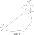
- FIG 4 shows the structure 400 in side view along the inboard direction; figure 5 shows the structure in front view; figure 6 shows the structure in top, or plan view, figure 7 shows the structure in side view along the outboard direction and figure 8 shows the structure in crosssection in a plane perpendicular to the x-axis.
- figures and other figures described herein contain dimensions of the structure. It is to be understood that these dimensions are merely an example and various other dimensions may be used without departing from the principles described herein. The dimension of the structure may for example depend upon the aerofoil and/or aircraft to which the structure is attached or integrally formed with.
- the structure 400 comprises a body 402.
- the body is shaped, or dimensioned, so as to generate lift when subjected to an oncoming fluid flow, and as such may be referred to as being of an aerofoil shape. It extends in a spanwise direction (in these examples it has a span of approximately 600 mm).
- the body has a leading edge 404 and a trailing edge 406. It has an inboard end 424 and an outboard end 426. It further has a lower side 408 and an upper side 410.
- the upper side 410 is in the region of relative low pressure and the lower side 408 is in the region of relative high pressure.
- the lower side 408 may therefore be referred to as the high pressure side of the body, and the upper side 410 may be referred to as the low pressure side of the body. Both the high pressure side and the low pressure side extend between the leading edge and trailing edge of the body.
- the body is canted and swept.
- the leading edge of the body 404 forms a sweep angle of approximately 66 degrees.
- the body may have increasing degrees of cant along its spanwise extent in the outboard direction. That is, the outboard end of the body may be disposed at a greater cant angle than the inboard end of the body. In these examples the maximum cant angle of the body is approximately 26 degrees. Because the body is swept and canted, it has a chord length which is a function of the position along the body's span. As can be seen with reference to figure 6 , the chord length decreases in the outboard direction towards the tip of the body.
- the body comprises at its outboard end opposing outer, or external, surfaces 412 and 414.
- Outer surface 412 forms part of the low pressure side of the body and outer surface 414 forms part of the high pressure side of the body.
- the outer surfaces may be symmetrical or near symmetrical about an axis 416, and may extend along the chordwise direction of the body. Axis 416 may define the maximum cant angle of the body.
- the outer surfaces may additionally be cambered. The camber of the outer surfaces may be greater than the camber of the remaining surfaces of the upper side 410 and lower side 408. That is, the outer surfaces 412 and 414 may have a camber angle that exceeds that of the remaining surfaces forming the upper and lower sides of the body.
- the body further comprises an intake surface 448 on the high pressure side of the body that feeds into a duct 428 extending through the body from a first opening 418 to a second opening 420 (best seen with reference to figure 8 ).
- the first opening is located in the high pressure region below the wing and the second opening is located in the low pressure region above the wing.
- the first opening is located on the lower side of the body. It may be located at the base of the outer surface 414.
- the second opening is located on the low pressure aspect of the wing.
- the body may be shaped so that the centroid of the second opening is vertically above the centroid of the first opening (i.e.
- the centroids have the same x and y coordinates), but in this example the body is shaped so that the second opening is located outboard and aft relative to the first opening on the high pressure aspect of the wing.
- the duct therefore extends in an outboard and aft direction from the first opening to the second opening.
- the intake surface 448 may similarly extend generally in the outboard and upwards direction towards the duct inlet and may therefore be swept relative to the chordline of the body.
- Figure 9 shows the tip region of an aircraft wing with the wake-influencing device indicated at 400.
- the duct housed within the body of the device is illustrated at 428.
- Figure 10 is a view of the underside of a wing 1000 illustrating the duct's first opening 418 on the high pressure aspect of the wing. This view illustrates how the intake surface 448 feeds into the duct.
- Figure 11 shows a view through the duct along the direction from the first opening 418 towards the second opening 420.
- first and second openings may extend along the chord length of the body or a substantial part thereof.
- the duct may therefore extend along the full chord length of the body (or a substantial part thereof).
- the chord length of a chord C at an arbitrary position within the duct is shown at 422 for the purposes of illustration in figures 6 and 9 .
- the first opening may be generally orientated along the chord line of the body (i.e. the opening is oriented along the general direction of the chord of the body).
- the first opening may be swept relative to the chord line of the body. It may for example be oriented, or inclined, outboard by approximately 5 degrees relative to the chord line of the body. It has been found that this is an effective arrangement for entraining oncoming fluid through the first opening into the duct.
- the width of the first opening may vary as a function of position along the chord of the body. That is, the width of the first opening may vary along its length. The width may increase and decrease along the chord of the body in a rolling arrangement.
- the front, or leading, edge of the opening is shown at 1102, and the rear edge shown at 1104.
- the front edge of the opening is the edge located in the vicinity of the leading edge of the body 404.
- the rear edge of the opening is the edge located in the vicinity of the trailing edge of the body.
- the width of the opening, w increases from the front edge along the chordwise direction before reaching a maximum width w max . Thereafter, the width of the opening decreases along the chord direction towards the rear edge.
- rolling-swept intake An opening with a rolling width profile and that is swept relative to the chord line of the body may be referred to as rolling-swept intake.
- a rolling-swept intake may be effective at entraining oncoming fluid into the duct.
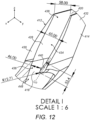
- the duct 428 is shown in more detail in figure 12 , which shows an enlarged view of the region 1 in figure 8 .
- the duct is defined by walls, or boundaries, which form part of the body. These walls further define the opposing outer surfaces 412 and 414: that is, the interior surface of the wall defines the duct, and the exterior surface of the wall defines the opposing outer surfaces.
- the duct is defined by an inboard wall 430 and an outboard wall 432.
- the inboard and outboard walls may be formed from a continuous, or single, surface. In that case, the 'inboard' wall may refer to the portion of the continuous wall that is on the inboard side, and the 'outboard' wall may refer to the portion of the continuous wall that is on the outboard side.
- the duct comprises a plenum 434 located between the first and second openings, and a first restriction 436 located between the plenum and the first opening.
- the duct additionally comprises a second restriction 438 between the plenum and the second opening.
- the width of the second restriction may be larger than the first restriction, but smaller than the width of the plenum.
- the diameter of the first restriction is approximately 46mm
- the diameter of the plenum approximately 65mm
- the diameter of the second restriction approximately 58 mm.
- the duct may therefore be described as comprising a venturi in the vicinity of the first opening that expands into the plenum, with the plenum reducing to a second venturi in the vicinity of the second opening.
- the duct thus has a converging-diverging-converging profile along its extent between the first and second openings.
- the inboard board wall 430 may be concave so as to at least in part define the restrictions and plenum.
- the outboard wall of the duct 432 may define a fluid-arresting structure, or formation, 440 that, when the aerofoil is exposed to oncoming fluid flow, generates a region of relative high pressure within the duct.
- the structure 440 may be located in the vicinity of the first opening.
- the fluid arresting structure defines the outboard edge of the duct's first opening.
- the inboard side of the duct's first opening is formed from the intake surface 448.
- the fluid-arresting structure may be any suitable abrupt formation (e.g. it may be mushroom shaped, or rectangular), but in this example is a convex portion of the outboard wall of the duct.
- the fluid-arresting structure may therefore be said to be in the shape of an aerofoil nose section, i.e. the structure may be shaped similarly to the front portion of an aerofoil that encompasses the aerofoil leading edge.
- the nose section may define a leading edge radius, in this example of approximately 12mm.
- the aerofoil structure 440 may have an associated chordline C D that extends into the duct towards the second opening. That is, the chordline of the structure lies in a direction parallel to, or approximately parallel to, the longitudinal direction of the duct between the first and second openings. The chordline may therefore be parallel, or approximately parallel to the maximum cant angle of the body.
- the structure may be oriented so that its leading edge is in the vicinity of the first opening.
- the structure may further extend across the duct in a direction generally parallel to the chordline of the body. Thus the structure may extend generally along the x-axis. It may extend across the full chord length of the duct.
- the structure 400 for influencing the wake is a standalone component capable of being fitted to the tip, or outboard end, of an aircraft wing.
- the structure may as such comprise an inboard surface 442 (best seen with reference to figure 7 ) that has a mating region configured to conform to the shape of the corresponding portion of the wing tip.
- the mating surface 442 of the device may for example be configured to exactly mate with a corresponding surface of the wing to which it is to be attached.
- the structure 400 may alternatively be integrally formed with the aircraft wing so as to form part of the wing.
- Figure 13 illustrates the streamlines of fluid flowing through the duct in normal operation.
- 'Normal operation' may refer to the wake-influencing structure 400 being attached to or otherwise forming part of an aircraft wing subject to an oncoming fluid flow at a freestream velocity.
- 'Normal use' may refer to the aircraft being at cruising speed, or when the aircraft is ascending (i.e. during the climbing phase of a flight) or descending (i.e. during the landing phase of a flight).
- fluid flows into the duct through opening 418 on the high pressure side and exits the duct through the opening 420 on the low pressure side.
- the first opening 418 may therefore be referred to as an inlet
- the second opening 420 may therefore be referred to as an outlet, or exhaust.
- the duct is configured so that the fluid exiting the exhaust is in the form of two rotating flows 1302 and 1304 that extend substantially in the direction of the freestream flow to which the wing is subjected.
- the oncoming fluid (indicated generally at 1306) may be entrained into the duct by the intake surface 448 and rolling-swept inlet 418.
- the sweep angle of the inlet relative to the chordline of the body (which may be approximately 5 degrees) may assist in entraining the oncoming fluid flow.
- the intake surface 448 is smoothly curved and extends generally in an upward and outboard direction towards the second opening to encourage part of the fluid flow through the duct to remain attached to the inboard wall.
- the attached flow is indicated by the dashed markings at 1308.
- the intake surface is contoured so as to cause part of the incoming fluid through the duct along the inboard side to adopt a rotational component. That is, the transition of the attached flow along the intake surface towards the duct inlet imparts a vorticity into the flow.
- the intake surface 448 is generally convex so as to impart an anti-clockwise rotational component into the attached flow
- the part of the fluid flow that enters the duct through the inboard side of the inlet has a velocity close to, or approximately equal to, the freestream velocity of the oncoming flow. More specifically, CFD studies have found that for a free stream velocity of 202ms -1 , the velocity of a stream tube entering the duct at its inboard side was approximately 190ms -1 .
- the fluid-arresting formation 440 on the outboard wall of the duct facilitates a reduction in velocity of the entrained fluid and thus an increase in fluid pressure within the duct.
- the structure 440 thus generates a region of relative high pressure within the duct, indicated at 1310. Due to the location of the fluid-arresting formation on the outboard side of the duct, the velocity of the fluid entering the duct is reduced within the outboard region of the duct inlet.
- the fluid-arresting structure in contrast to the smoothly curved intake surface, is an abrupt formation that may reduce the velocity of fluid entering the duct by encouraging a turbulent flow (and thus a thickening of the boundary layer) in the duct's outboard region in the vicinity of the inlet.
- the generated region of high pressure may be localised within the duct. That is, the region of high pressure may occupy a sub-volume, or sub-region, of the duct. As such, the region of high pressure may be referred to as a high pressure core.
- the fluid-arresting structure generates a high pressure core that exists within the duct's first restriction and plenum, and is locate in situ on the outboard side of the duct. The region of relative high pressure therefore generates a fluid pressure and velocity imbalance between the inboard and outboard sides of the duct within the first restriction and plenum.
- the structure 440 may be trip stripped around the radius of its nose. This may assist in facilitating the reduction in velocity of the entrained fluid by encouraging the development of the turbulent flow.
- the trip strip may extend across the structure in the chordwise direction of the body.
- suitable dimensions of the trip strip may for example be approximately 1 mm in depth and a surface area coverage within the duct of between approximately 18,000mm 2 and 36,000mm 2 .
- the duct 418 has a cross-sectional area profile (i.e. the cross-sectional area varies as a function of position along the duct in the general longitudinal direction) that causes the high pressure region 1310 to adopt an aerofoil shape that is oriented generally along the longitudinal direction of the duct.
- a cross-sectional area profile i.e. the cross-sectional area varies as a function of position along the duct in the general longitudinal direction
- the interaction of the relatively low pressure region on the inboard side of the duct and the increase in the duct's cross-sectional area from the first restriction into the plenum causes the high pressure region to adopt the aerofoil shape.
- the boundary of the relative high pressure region is convex.
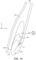
- Figures 14 and 15 show the high pressure core in more detail.
- Figure 14 shows a schematic illustration of the high pressure core and figure 15 shows the pressure field obtained from CFD analysis within a duct designed by the inventor and fitted to Embraer ERJ145 wing exposed to a freestream velocity of approximately 200ms -1 .
- the high pressure core is indicated generally at 1400.
- the core is shown as extending along approximately 50-70% the length of the duct.
- the magnitude of the fluid velocity is less than approximately 60ms -1 when the freestream velocity of the oncoming fluid flow is between 190ms -1 and 210ms-'.
- the fluid velocity/pressure may not be constant within the core but the core may instead exhibit a pressure/velocity gradient therein.
- the core contains a first sub-region 1420 wherein the fluid velocity is less than approximately 15ms -1 , and a second sub-region 1430 wherein the fluid velocity is less than approximately 30ms -1 .
- the first and second sub-regions may be in a nested arrangement (in this case the first sub-region is nested within the second sub-region).
- Figure 15 shows the high pressure core indicated generally at 1500 within duct 1502.
- the body housing the duct is indicated generally at 1504, and has a high pressure side 1506 and a low pressure side 1508.
- Intake surface 1510 feeds into the duct inlet 1512.
- the fluid-arresting structure that contributes to the development of the high pressure core is shown at 1514. It can be seen that within the high pressure core the fluid velocity is less than approximately 50ms -1 .
- the high pressure core adopts an aerofoil shape with a boundary that is convex.
- the core 1500 comprises a plurality of approximately isobaric regions in a nested arrangement with a pressure/velocity gradient such that the inner regions are of higher pressure/lower velocity than the outer regions.
- the pressure field shows that within a region of the core the fluid velocity is less than 15ms -1 .
- the pressure field further illustrates the fluid velocity/pressure imbalance between the inboard 1516 and outboard 1518 sides of the duct.
- part of the fluid flow through the duct adopts streamlines that follow the aerofoil shape of the high pressure region thereby causing that fluid flow to adopt a clockwise rotational component.
- part of the inlet flow 1312 follows the camber prescribed by the high pressure region towards the plenum and adopts a rotational component opposite in direction to the fluid flow along the inboard direction. In this manner the region of high pressure within the duct causes part of the fluid flow therethrough to adopt a rotational component.
- the divergence of the flow within the duct is maintained as the fluid exits the duct and causes the exiting fluid to be in the form of two opposing vorticity flows.
- the duct can be configured in such a way as to generate a high pressure core within the duct that leads to the creation of fluid flow within the duct with balanced divergent streamlines. When such a flow exits the duct through the second opening it may take the form of two opposing vorticity flows of substantially equal vorticity magnitude.
- the body 402 may be configured so that its exterior surfaces are shaped, or contoured, to generate a pressure field in the region of the tip of the wing that pressure balances these two rotating flows. This pressure balancing may encourage the two rotating flows to interact so that their vorticities substantially cancel in the near downstream of the wing, reducing the induced drag of the aerofoil.
- CFD analysis has shown that for an Embraer ERJ145 regional airliner at 36,000 feet and Mach 0.686 (202.5ms -1 ), a wake-controlling device similar to that described above led to the cancellation of wingtip vortices at approximately 1.75m aft of the wingtip trailing edge. This compares favourably with normal aerofoils comprising winglets, where wingtip vortices may be present in the aerofoil's wake for up to three kilometres.
- the pressure balancing of the rotating flows generated by the duct may be achieved by the outer surfaces 412 and 414.
- surface 414 which forms part of the high pressure side of the body 408 may be cambered so as to generate a localised region of relative low pressure outboard of the fluid inlet 418 on the high pressure aspect of the wing.
- surface 412 which forms part of the low pressure side of the body may be cambered so as to generate a localised region of relative low pressure inboard of the outlet 420 on the low pressure side that pressure balances the localised low-pressure region below the lower side of the body indicated in the region shown by 414.
- the body 402 may further be configured so as to inhibit the effects of the trailing vortex sheet shed from the trailing edge of the wing. It has been described above with reference to figure 1 that this vortex sheet may be generated from the interaction at the wing's trailing edge of the streamlines over the upper surface of the wing converging to the fuselage, and the streamlines over the lower surface of the wing diverging from the fuselage. It has been found that the localised region of relative low pressure generated by the cambered outer surface 412 at the outboard end of the upper side of the body 410 can oppose the positive pressure gradient that may exist along the upper surface of the wing in the outboard direction.
- the generated low-pressure region operates to re-orientate the flow over the upper side of the body 410 towards the flow over the lower side of the body 408.
- the outer surface 412 operates to re-orientate the streamlines over the upper side of the body (and the aerofoil) to better, or more closely, match the streamlines over the lower side of the body (and aerofoil) by turning the streamlines outboard. Re-orienting the streamlines over the upper and lower surfaces may inhibit the creation of vortices at the trailing edge, thus potentially further reducing the induced drag of the wing.
- FIG 16 is a schematic illustration of a CFD image obtained by the inventor (which is shown in figure 17 ).
- the high pressure region beneath the wing is illustrated generally at 1602, and the low pressure region above the wing is illustrated generally at 1604.
- the low pressure region includes an area 1606 located above the wing at its outboard end in the vicinity of the wing tip. This area corresponds to the low pressure region generated from the cambered outer surface 412 and is located inboard of the duct outlet.
- the low pressure region further includes a region 1608 located beneath the lower surface of the wing at its outboard end in the vicinity of the wingtip. This low pressure region extends outboard of the duct inlet 418 and corresponds to the region of low pressure generated by cambered outer surface 414.
- Low pressure regions 1606 and 1608 operate to pressure balance the opposing rotating flow that exits the outlet 420 as described above.
- Figure 17 shows the pressure field around an aircraft obtained from CFD analysis.
- the low pressure region above the wings of the aircraft is indicated generally at 1702, and the high pressure region below the aircraft is indicated generally at 1704.
- the localised region of low pressure on the outboard side of the wingtip on the high pressure side is shown at 1708. This corresponds to the region of localised region of low pressure generated from the outer surface 414.
- the localised region of low pressure on the inboard side of the body on the low pressure side is shown at 1706. This region corresponds to the region of low pressure generated from outer surface 412.
- Examples of the wake-controlling device described above may therefore reduce the induced drag of an aircraft wing by reducing the effect of both wing tip and trailing vortices. Reducing the induced drag may enable the wings to generate a required level of lift at a decreased angle of attack compared to a normal wing and with reduced thrust provided from the engines.
- the device may enable aircrafts to reduce fuel consumption.
- a wake-influencing device as described above could lead to an improvement of circa 15% in an aircraft's lift to drag ratio (L/D) during cruise, which corresponds to an approximate 10% fuel saving.
- L/D lift to drag ratio
- the device could provide a circa 20% improvement in the LID ratio, corresponding to a circa 15% fuel saving.
- the device could provide a circa 10% improvement in an aircraft's lift to drag ratio (L/D), corresponding to an approximate 5% fuel saving. It is therefore believed that a device as described herein has the potential to lead to substantial cost savings for aircraft.
- the device reduces the potentially damaging effects of wingtip vortices generated by normal aircraft wings by causing the vortices to be cancelled in the near downstream of the wing.
- the device may enable the wingtip vortices to be substantially cancelled aft of the wing without generating any additional tension and/or torsion in the wing. This is because the device manipulates fluid flowing therethrough to cancel the wingtip vortices via a fluid-fluid interaction, as opposed to a fluid-structure interaction.
- the device may be fitted to an existing wing without requiring that the wing undergo spar strengthening (as is often required when fitting winglets), meaning existing wings may be modified with reduced operational down time, potentially leading to further cost savings.
- the wing can effectively be modelled as a section of an infinite trapezoidal wing.
- Equation (7) gives an estimated bending moment for the modified wing of 4.91 ⁇ 10 5 Nm .
- the loss of pressure due to fluid escaping through the duct was considered, but found to only incur a negligible ⁇ 80Nm moment in the opposite direction to the bending moment due to lift. This was found from Computational Fluid Dynamic (CFD) simulations of the wingtip.
- CFD Computational Fluid Dynamic
- a device for modifying the wake of an aerofoil in the form of an aircraft wing in the form of an aircraft wing. It will be appreciated that this is for the purposes of illustration only and that the principles of the device as described herein may applied to any aerofoil. That is, a device for modifying the wake of an aerofoil as described herein may be applied to any suitable aerofoil such as, for example, helicopter rotor blades, wind turbines, fans, a marine underwater turbine blade, a propeller blade or a hydrofoil.
- the value ⁇ is a dimensionless value that represents the position along the Sears-Haack body at which the duct starts.
Landscapes
- Engineering & Computer Science (AREA)
- Aviation & Aerospace Engineering (AREA)
- Structures Of Non-Positive Displacement Pumps (AREA)
Applications Claiming Priority (2)
| Application Number | Priority Date | Filing Date | Title |
|---|---|---|---|
| GBGB1512480.3A GB201512480D0 (en) | 2015-07-16 | 2015-07-16 | Fluid flow control for an aerofoil |
| PCT/GB2016/052167 WO2017009670A1 (en) | 2015-07-16 | 2016-07-18 | Fluid flow control for an aerofoil |
Publications (2)
| Publication Number | Publication Date |
|---|---|
| EP3310653A1 EP3310653A1 (en) | 2018-04-25 |
| EP3310653B1 true EP3310653B1 (en) | 2023-08-23 |
Family
ID=54014076
Family Applications (1)
| Application Number | Title | Priority Date | Filing Date |
|---|---|---|---|
| EP16750993.4A Active EP3310653B1 (en) | 2015-07-16 | 2016-07-18 | Fluid flow control for an aerofoil |
Country Status (6)
| Country | Link |
|---|---|
| US (1) | US10919618B2 (da) |
| EP (1) | EP3310653B1 (da) |
| CN (1) | CN107848619B (da) |
| DK (1) | DK3310653T3 (da) |
| GB (2) | GB201512480D0 (da) |
| WO (1) | WO2017009670A1 (da) |
Families Citing this family (4)
| Publication number | Priority date | Publication date | Assignee | Title |
|---|---|---|---|---|
| US10407164B2 (en) * | 2016-10-28 | 2019-09-10 | Honeywell International Inc. | Air distribution system with drag reducing inlet |
| WO2018130612A1 (en) * | 2017-01-12 | 2018-07-19 | Infinity Holding B.V. | A device for influencing the wake flow of an aerofoil, aerofoil comprising such a device, and aircraft comprising such an aerofoil |
| NL2018783B1 (en) * | 2017-01-12 | 2018-07-25 | Infinity Holding B V | A device for influencing the wake flow of an aerofoil, aerofoil comprising such a device, and aircraft comprising such an aerofoil |
| CN112124561B (zh) * | 2020-09-27 | 2022-02-25 | 中国商用飞机有限责任公司 | 用于飞行器的翼梢小翼的气动减阻结构及飞行器 |
Family Cites Families (23)
| Publication number | Priority date | Publication date | Assignee | Title |
|---|---|---|---|---|
| US2075817A (en) * | 1934-08-17 | 1937-04-06 | Arthur W Loerke | Wing vortex reducer |
| GB732617A (en) | 1952-07-09 | 1955-06-29 | Karin Maria Turton | Improvements in or relating to wing units and the like for aircraft |
| US3144220A (en) * | 1962-02-23 | 1964-08-11 | Mathias H Kittelson | Control apparatus |
| US4382569A (en) | 1979-12-26 | 1983-05-10 | Grumman Aerospace Corporation | Wing tip flow control |
| US4478380A (en) * | 1982-12-03 | 1984-10-23 | Frakes James F | Wing tip vortices suppressor |
| DE3836673A1 (de) * | 1988-10-28 | 1990-05-03 | Michael Harriehausen | Verfahren und anordnung zur verminderung des induzierten widerstandes eines fluegels |
| US5348253A (en) * | 1993-02-01 | 1994-09-20 | Gratzer Louis B | Blended winglet |
| US5806807A (en) * | 1995-10-04 | 1998-09-15 | Haney; William R. | Airfoil vortex attenuation apparatus and method |
| US5791875A (en) * | 1996-09-10 | 1998-08-11 | Mcdonnell Douglas Helicopter Co. | Tip vortex reduction system |
| US6474604B1 (en) * | 1999-04-12 | 2002-11-05 | Jerry E. Carlow | Mobius-like joining structure for fluid dynamic foils |
| US6368059B1 (en) | 2000-07-28 | 2002-04-09 | Lockheed Martin Corporation | Controlled passive porosity systems to mitigate cavitation |
| US7207526B2 (en) * | 2002-06-26 | 2007-04-24 | Mccarthy Peter T | High efficiency tip vortex reversal and induced drag reduction |
| US7100875B2 (en) * | 2004-02-20 | 2006-09-05 | The Boeing Company | Apparatus and method for the control of trailing wake flows |
| CN201023655Y (zh) * | 2007-03-16 | 2008-02-20 | 雷良榆 | 机翼翼梢反方向旋流装置 |
| GB0802000D0 (en) | 2008-02-04 | 2008-03-12 | Wingtec Holdings Ltd | Aerofoil control devices |
| US8128035B2 (en) * | 2008-04-15 | 2012-03-06 | The Boeing Company | Winglets with recessed surfaces, and associated systems and methods |
| EP2404517A1 (en) | 2009-03-02 | 2012-01-11 | JMI Co., Ltd | Fixing device of ornament and method for fixing ornament by fixing device |
| US8651813B2 (en) * | 2009-05-29 | 2014-02-18 | Donald James Long | Fluid dynamic body having escapelet openings for reducing induced and interference drag, and energizing stagnant flow |
| US8490926B2 (en) * | 2010-01-29 | 2013-07-23 | The Boeing Company | Multi-stage flow control actuation |
| GB2468978B (en) * | 2010-04-27 | 2012-04-04 | Aerodynamic Res Innovation Holdings Ltd | Fluid flow control device for an aerofoil |
| US8960609B2 (en) * | 2011-12-15 | 2015-02-24 | Lockheed Martin Corporation | Minimally intrusive wingtip vortex wake mitigation using inside-mold-line surface modifications |
| EP2644497B1 (en) * | 2012-03-29 | 2016-01-20 | Airbus Operations GmbH | Wing for an aircraft, aircraft and method for reducing aerodynamic drag and improving maximum lift |
| US20170073062A1 (en) * | 2015-09-12 | 2017-03-16 | Gregory S. Firth | Variable Geometry Wingtip |
-
2015
- 2015-07-16 GB GBGB1512480.3A patent/GB201512480D0/en not_active Ceased
-
2016
- 2016-07-18 US US15/743,720 patent/US10919618B2/en active Active
- 2016-07-18 CN CN201680041978.XA patent/CN107848619B/zh active Active
- 2016-07-18 WO PCT/GB2016/052167 patent/WO2017009670A1/en active Application Filing
- 2016-07-18 GB GB1612416.6A patent/GB2542664B/en active Active
- 2016-07-18 EP EP16750993.4A patent/EP3310653B1/en active Active
- 2016-07-18 DK DK16750993.4T patent/DK3310653T3/da active
Also Published As
| Publication number | Publication date |
|---|---|
| GB201612416D0 (en) | 2016-08-31 |
| US20180201364A1 (en) | 2018-07-19 |
| WO2017009670A1 (en) | 2017-01-19 |
| GB2542664A (en) | 2017-03-29 |
| EP3310653A1 (en) | 2018-04-25 |
| GB2542664B (en) | 2018-03-14 |
| GB201512480D0 (en) | 2015-08-19 |
| CN107848619A (zh) | 2018-03-27 |
| US10919618B2 (en) | 2021-02-16 |
| CN107848619B (zh) | 2021-10-26 |
| DK3310653T3 (da) | 2023-09-25 |
Similar Documents
| Publication | Publication Date | Title |
|---|---|---|
| CN107757879B (zh) | 用于飞行器的机翼的翼尖装置、飞行器及用途 | |
| Selby et al. | Control of low-speed turbulent separated flow using jet vortex generators | |
| US8485476B2 (en) | Discrete co-flow jet (DCFJ) airfoil | |
| US20110260008A1 (en) | Fluid flow control device for an aerofoil | |
| US7134631B2 (en) | Vorticity cancellation at trailing edge for induced drag elimination | |
| US8186617B2 (en) | Aircraft having a lambda-box wing configuration | |
| US10625847B2 (en) | Split winglet | |
| US20090065631A1 (en) | Emissionless silent and ultra-efficient airplane using cfj airfoil | |
| EP3310653B1 (en) | Fluid flow control for an aerofoil | |
| US20090014592A1 (en) | Co-flow jet aircraft | |
| US20110309202A1 (en) | Wingtec Holding Limited | |
| US6318677B1 (en) | Method and apparatus for generating a stable leading-edge lifting-vortex controller | |
| EP2604517B1 (en) | Airfoil comprising a minimally intrusive wingtip vortex mitigation device | |
| Boermans | Research on sailplane aerodynamics at Delft University of Technology | |
| EP2604516A2 (en) | Minimally intrusive wingtip vortex wake mitigation using microvane arrays | |
| US20220297829A1 (en) | Lift enhancement assembly of an aerial vehicle with fixed wings | |
| US4860976A (en) | Attached jet spanwise blowing lift augmentation system | |
| EP0052360A1 (en) | Air aspiration device of aircraft-mounted gas-turbine engine | |
| WO2018130612A1 (en) | A device for influencing the wake flow of an aerofoil, aerofoil comprising such a device, and aircraft comprising such an aerofoil | |
| NL2018783B1 (en) | A device for influencing the wake flow of an aerofoil, aerofoil comprising such a device, and aircraft comprising such an aerofoil | |
| Ahluwalia et al. | CFD analysis on different shapes of winglet at low subsonic flow | |
| WO2019239123A1 (en) | Wing-tip device | |
| Palmer et al. | Effect of Curved Boundary Layer Fences on Aerodynamic Efficiency | |
| Rozbytskyi et al. | The Influence of Leading Edge Vortex Generators on the Efficiency of Lateral Control Surfaces | |
| WO2004094227A1 (en) | Apparatus and method for the reduction of drag |
Legal Events
| Date | Code | Title | Description |
|---|---|---|---|
| STAA | Information on the status of an ep patent application or granted ep patent |
Free format text: STATUS: THE INTERNATIONAL PUBLICATION HAS BEEN MADE |
|
| PUAI | Public reference made under article 153(3) epc to a published international application that has entered the european phase |
Free format text: ORIGINAL CODE: 0009012 |
|
| STAA | Information on the status of an ep patent application or granted ep patent |
Free format text: STATUS: REQUEST FOR EXAMINATION WAS MADE |
|
| 17P | Request for examination filed |
Effective date: 20180116 |
|
| AK | Designated contracting states |
Kind code of ref document: A1 Designated state(s): AL AT BE BG CH CY CZ DE DK EE ES FI FR GB GR HR HU IE IS IT LI LT LU LV MC MK MT NL NO PL PT RO RS SE SI SK SM TR |
|
| AX | Request for extension of the european patent |
Extension state: BA ME |
|
| DAV | Request for validation of the european patent (deleted) | ||
| DAX | Request for extension of the european patent (deleted) | ||
| STAA | Information on the status of an ep patent application or granted ep patent |
Free format text: STATUS: EXAMINATION IS IN PROGRESS |
|
| STAA | Information on the status of an ep patent application or granted ep patent |
Free format text: STATUS: EXAMINATION IS IN PROGRESS |
|
| 17Q | First examination report despatched |
Effective date: 20211105 |
|
| GRAP | Despatch of communication of intention to grant a patent |
Free format text: ORIGINAL CODE: EPIDOSNIGR1 |
|
| STAA | Information on the status of an ep patent application or granted ep patent |
Free format text: STATUS: GRANT OF PATENT IS INTENDED |
|
| INTG | Intention to grant announced |
Effective date: 20230316 |
|
| GRAS | Grant fee paid |
Free format text: ORIGINAL CODE: EPIDOSNIGR3 |
|
| GRAA | (expected) grant |
Free format text: ORIGINAL CODE: 0009210 |
|
| STAA | Information on the status of an ep patent application or granted ep patent |
Free format text: STATUS: THE PATENT HAS BEEN GRANTED |
|
| AK | Designated contracting states |
Kind code of ref document: B1 Designated state(s): AL AT BE BG CH CY CZ DE DK EE ES FI FR GR HR HU IE IS IT LI LT LU LV MC MK MT NL NO PL PT RO RS SE SI SK SM TR |
|
| RBV | Designated contracting states (corrected) |
Designated state(s): AL AT BE BG CH CY CZ DE DK EE ES FI FR GR HR HU IE IS IT LI LT LU LV MC MK MT NL NO PL PT RO RS SE SI SK SM TR |
|
| REG | Reference to a national code |
Ref country code: CH Ref legal event code: EP |
|
| REG | Reference to a national code |
Ref country code: IE Ref legal event code: FG4D |
|
| REG | Reference to a national code |
Ref country code: DE Ref legal event code: R096 Ref document number: 602016082133 Country of ref document: DE |
|
| P01 | Opt-out of the competence of the unified patent court (upc) registered |
Effective date: 20230814 |
|
| REG | Reference to a national code |
Ref country code: DK Ref legal event code: T3 Effective date: 20230918 |
|
| REG | Reference to a national code |
Ref country code: LT Ref legal event code: MG9D |
|
| REG | Reference to a national code |
Ref country code: NL Ref legal event code: MP Effective date: 20230823 |
|
| REG | Reference to a national code |
Ref country code: AT Ref legal event code: MK05 Ref document number: 1602324 Country of ref document: AT Kind code of ref document: T Effective date: 20230823 |
|
| PG25 | Lapsed in a contracting state [announced via postgrant information from national office to epo] |
Ref country code: GR Free format text: LAPSE BECAUSE OF FAILURE TO SUBMIT A TRANSLATION OF THE DESCRIPTION OR TO PAY THE FEE WITHIN THE PRESCRIBED TIME-LIMIT Effective date: 20231124 |
|
| PG25 | Lapsed in a contracting state [announced via postgrant information from national office to epo] |
Ref country code: IS Free format text: LAPSE BECAUSE OF FAILURE TO SUBMIT A TRANSLATION OF THE DESCRIPTION OR TO PAY THE FEE WITHIN THE PRESCRIBED TIME-LIMIT Effective date: 20231223 |
|
| PG25 | Lapsed in a contracting state [announced via postgrant information from national office to epo] |
Ref country code: SE Free format text: LAPSE BECAUSE OF FAILURE TO SUBMIT A TRANSLATION OF THE DESCRIPTION OR TO PAY THE FEE WITHIN THE PRESCRIBED TIME-LIMIT Effective date: 20230823 Ref country code: RS Free format text: LAPSE BECAUSE OF FAILURE TO SUBMIT A TRANSLATION OF THE DESCRIPTION OR TO PAY THE FEE WITHIN THE PRESCRIBED TIME-LIMIT Effective date: 20230823 Ref country code: PT Free format text: LAPSE BECAUSE OF FAILURE TO SUBMIT A TRANSLATION OF THE DESCRIPTION OR TO PAY THE FEE WITHIN THE PRESCRIBED TIME-LIMIT Effective date: 20231226 Ref country code: NO Free format text: LAPSE BECAUSE OF FAILURE TO SUBMIT A TRANSLATION OF THE DESCRIPTION OR TO PAY THE FEE WITHIN THE PRESCRIBED TIME-LIMIT Effective date: 20231123 Ref country code: NL Free format text: LAPSE BECAUSE OF FAILURE TO SUBMIT A TRANSLATION OF THE DESCRIPTION OR TO PAY THE FEE WITHIN THE PRESCRIBED TIME-LIMIT Effective date: 20230823 Ref country code: LV Free format text: LAPSE BECAUSE OF FAILURE TO SUBMIT A TRANSLATION OF THE DESCRIPTION OR TO PAY THE FEE WITHIN THE PRESCRIBED TIME-LIMIT Effective date: 20230823 Ref country code: LT Free format text: LAPSE BECAUSE OF FAILURE TO SUBMIT A TRANSLATION OF THE DESCRIPTION OR TO PAY THE FEE WITHIN THE PRESCRIBED TIME-LIMIT Effective date: 20230823 Ref country code: IS Free format text: LAPSE BECAUSE OF FAILURE TO SUBMIT A TRANSLATION OF THE DESCRIPTION OR TO PAY THE FEE WITHIN THE PRESCRIBED TIME-LIMIT Effective date: 20231223 Ref country code: HR Free format text: LAPSE BECAUSE OF FAILURE TO SUBMIT A TRANSLATION OF THE DESCRIPTION OR TO PAY THE FEE WITHIN THE PRESCRIBED TIME-LIMIT Effective date: 20230823 Ref country code: GR Free format text: LAPSE BECAUSE OF FAILURE TO SUBMIT A TRANSLATION OF THE DESCRIPTION OR TO PAY THE FEE WITHIN THE PRESCRIBED TIME-LIMIT Effective date: 20231124 Ref country code: FI Free format text: LAPSE BECAUSE OF FAILURE TO SUBMIT A TRANSLATION OF THE DESCRIPTION OR TO PAY THE FEE WITHIN THE PRESCRIBED TIME-LIMIT Effective date: 20230823 Ref country code: AT Free format text: LAPSE BECAUSE OF FAILURE TO SUBMIT A TRANSLATION OF THE DESCRIPTION OR TO PAY THE FEE WITHIN THE PRESCRIBED TIME-LIMIT Effective date: 20230823 |
|
| PG25 | Lapsed in a contracting state [announced via postgrant information from national office to epo] |
Ref country code: PL Free format text: LAPSE BECAUSE OF FAILURE TO SUBMIT A TRANSLATION OF THE DESCRIPTION OR TO PAY THE FEE WITHIN THE PRESCRIBED TIME-LIMIT Effective date: 20230823 |
|
| PG25 | Lapsed in a contracting state [announced via postgrant information from national office to epo] |
Ref country code: ES Free format text: LAPSE BECAUSE OF FAILURE TO SUBMIT A TRANSLATION OF THE DESCRIPTION OR TO PAY THE FEE WITHIN THE PRESCRIBED TIME-LIMIT Effective date: 20230823 |
|
| PG25 | Lapsed in a contracting state [announced via postgrant information from national office to epo] |
Ref country code: SM Free format text: LAPSE BECAUSE OF FAILURE TO SUBMIT A TRANSLATION OF THE DESCRIPTION OR TO PAY THE FEE WITHIN THE PRESCRIBED TIME-LIMIT Effective date: 20230823 Ref country code: RO Free format text: LAPSE BECAUSE OF FAILURE TO SUBMIT A TRANSLATION OF THE DESCRIPTION OR TO PAY THE FEE WITHIN THE PRESCRIBED TIME-LIMIT Effective date: 20230823 Ref country code: ES Free format text: LAPSE BECAUSE OF FAILURE TO SUBMIT A TRANSLATION OF THE DESCRIPTION OR TO PAY THE FEE WITHIN THE PRESCRIBED TIME-LIMIT Effective date: 20230823 Ref country code: EE Free format text: LAPSE BECAUSE OF FAILURE TO SUBMIT A TRANSLATION OF THE DESCRIPTION OR TO PAY THE FEE WITHIN THE PRESCRIBED TIME-LIMIT Effective date: 20230823 Ref country code: CZ Free format text: LAPSE BECAUSE OF FAILURE TO SUBMIT A TRANSLATION OF THE DESCRIPTION OR TO PAY THE FEE WITHIN THE PRESCRIBED TIME-LIMIT Effective date: 20230823 Ref country code: SK Free format text: LAPSE BECAUSE OF FAILURE TO SUBMIT A TRANSLATION OF THE DESCRIPTION OR TO PAY THE FEE WITHIN THE PRESCRIBED TIME-LIMIT Effective date: 20230823 |