EP3310464B1 - Single weld contactor - Google Patents
Single weld contactor Download PDFInfo
- Publication number
- EP3310464B1 EP3310464B1 EP16815105.8A EP16815105A EP3310464B1 EP 3310464 B1 EP3310464 B1 EP 3310464B1 EP 16815105 A EP16815105 A EP 16815105A EP 3310464 B1 EP3310464 B1 EP 3310464B1
- Authority
- EP
- European Patent Office
- Prior art keywords
- cup body
- port
- cap
- membrane
- center tube
- Prior art date
- Legal status (The legal status is an assumption and is not a legal conclusion. Google has not performed a legal analysis and makes no representation as to the accuracy of the status listed.)
- Active
Links
Images


Classifications
-
- B—PERFORMING OPERATIONS; TRANSPORTING
- B01—PHYSICAL OR CHEMICAL PROCESSES OR APPARATUS IN GENERAL
- B01D—SEPARATION
- B01D63/00—Apparatus in general for separation processes using semi-permeable membranes
- B01D63/02—Hollow fibre modules
- B01D63/024—Hollow fibre modules with a single potted end
-
- B—PERFORMING OPERATIONS; TRANSPORTING
- B01—PHYSICAL OR CHEMICAL PROCESSES OR APPARATUS IN GENERAL
- B01D—SEPARATION
- B01D19/00—Degasification of liquids
- B01D19/0031—Degasification of liquids by filtration
-
- B—PERFORMING OPERATIONS; TRANSPORTING
- B01—PHYSICAL OR CHEMICAL PROCESSES OR APPARATUS IN GENERAL
- B01D—SEPARATION
- B01D27/00—Cartridge filters of the throw-away type
- B01D27/08—Construction of the casing
-
- B—PERFORMING OPERATIONS; TRANSPORTING
- B01—PHYSICAL OR CHEMICAL PROCESSES OR APPARATUS IN GENERAL
- B01D—SEPARATION
- B01D29/00—Filters with filtering elements stationary during filtration, e.g. pressure or suction filters, not covered by groups B01D24/00 - B01D27/00; Filtering elements therefor
- B01D29/88—Filters with filtering elements stationary during filtration, e.g. pressure or suction filters, not covered by groups B01D24/00 - B01D27/00; Filtering elements therefor having feed or discharge devices
-
- B—PERFORMING OPERATIONS; TRANSPORTING
- B01—PHYSICAL OR CHEMICAL PROCESSES OR APPARATUS IN GENERAL
- B01D—SEPARATION
- B01D35/00—Filtering devices having features not specifically covered by groups B01D24/00 - B01D33/00, or for applications not specifically covered by groups B01D24/00 - B01D33/00; Auxiliary devices for filtration; Filter housing constructions
- B01D35/30—Filter housing constructions
-
- B—PERFORMING OPERATIONS; TRANSPORTING
- B01—PHYSICAL OR CHEMICAL PROCESSES OR APPARATUS IN GENERAL
- B01D—SEPARATION
- B01D61/00—Processes of separation using semi-permeable membranes, e.g. dialysis, osmosis or ultrafiltration; Apparatus, accessories or auxiliary operations specially adapted therefor
-
- B—PERFORMING OPERATIONS; TRANSPORTING
- B01—PHYSICAL OR CHEMICAL PROCESSES OR APPARATUS IN GENERAL
- B01D—SEPARATION
- B01D63/00—Apparatus in general for separation processes using semi-permeable membranes
- B01D63/02—Hollow fibre modules
- B01D63/021—Manufacturing thereof
- B01D63/022—Encapsulating hollow fibres
-
- B—PERFORMING OPERATIONS; TRANSPORTING
- B01—PHYSICAL OR CHEMICAL PROCESSES OR APPARATUS IN GENERAL
- B01D—SEPARATION
- B01D63/00—Apparatus in general for separation processes using semi-permeable membranes
- B01D63/02—Hollow fibre modules
- B01D63/021—Manufacturing thereof
- B01D63/0232—Manufacturing thereof using hollow fibers mats as precursor, e.g. wound or pleated mats
-
- B—PERFORMING OPERATIONS; TRANSPORTING
- B01—PHYSICAL OR CHEMICAL PROCESSES OR APPARATUS IN GENERAL
- B01D—SEPARATION
- B01D63/00—Apparatus in general for separation processes using semi-permeable membranes
- B01D63/02—Hollow fibre modules
- B01D63/025—Bobbin units
-
- B—PERFORMING OPERATIONS; TRANSPORTING
- B01—PHYSICAL OR CHEMICAL PROCESSES OR APPARATUS IN GENERAL
- B01D—SEPARATION
- B01D63/00—Apparatus in general for separation processes using semi-permeable membranes
- B01D63/02—Hollow fibre modules
- B01D63/032—More than two tube sheets for one bundle
-
- B—PERFORMING OPERATIONS; TRANSPORTING
- B01—PHYSICAL OR CHEMICAL PROCESSES OR APPARATUS IN GENERAL
- B01D—SEPARATION
- B01D65/00—Accessories or auxiliary operations, in general, for separation processes or apparatus using semi-permeable membranes
- B01D65/003—Membrane bonding or sealing
-
- B—PERFORMING OPERATIONS; TRANSPORTING
- B01—PHYSICAL OR CHEMICAL PROCESSES OR APPARATUS IN GENERAL
- B01D—SEPARATION
- B01D69/00—Semi-permeable membranes for separation processes or apparatus characterised by their form, structure or properties; Manufacturing processes specially adapted therefor
- B01D69/08—Hollow fibre membranes
-
- B—PERFORMING OPERATIONS; TRANSPORTING
- B01—PHYSICAL OR CHEMICAL PROCESSES OR APPARATUS IN GENERAL
- B01D—SEPARATION
- B01D19/00—Degasification of liquids
-
- B—PERFORMING OPERATIONS; TRANSPORTING
- B01—PHYSICAL OR CHEMICAL PROCESSES OR APPARATUS IN GENERAL
- B01D—SEPARATION
- B01D2313/00—Details relating to membrane modules or apparatus
- B01D2313/02—Specific tightening or locking mechanisms
- B01D2313/025—Specific membrane holders
-
- B—PERFORMING OPERATIONS; TRANSPORTING
- B01—PHYSICAL OR CHEMICAL PROCESSES OR APPARATUS IN GENERAL
- B01D—SEPARATION
- B01D2313/00—Details relating to membrane modules or apparatus
- B01D2313/04—Specific sealing means
- B01D2313/041—Gaskets or O-rings
-
- B—PERFORMING OPERATIONS; TRANSPORTING
- B01—PHYSICAL OR CHEMICAL PROCESSES OR APPARATUS IN GENERAL
- B01D—SEPARATION
- B01D2313/00—Details relating to membrane modules or apparatus
- B01D2313/04—Specific sealing means
- B01D2313/042—Adhesives or glues
-
- B—PERFORMING OPERATIONS; TRANSPORTING
- B01—PHYSICAL OR CHEMICAL PROCESSES OR APPARATUS IN GENERAL
- B01D—SEPARATION
- B01D2313/00—Details relating to membrane modules or apparatus
- B01D2313/20—Specific housing
- B01D2313/205—Specific housing characterised by the shape
-
- B—PERFORMING OPERATIONS; TRANSPORTING
- B01—PHYSICAL OR CHEMICAL PROCESSES OR APPARATUS IN GENERAL
- B01D—SEPARATION
- B01D2313/00—Details relating to membrane modules or apparatus
- B01D2313/21—Specific headers, end caps
-
- B—PERFORMING OPERATIONS; TRANSPORTING
- B01—PHYSICAL OR CHEMICAL PROCESSES OR APPARATUS IN GENERAL
- B01D—SEPARATION
- B01D2313/00—Details relating to membrane modules or apparatus
- B01D2313/44—Cartridge types
-
- B—PERFORMING OPERATIONS; TRANSPORTING
- B01—PHYSICAL OR CHEMICAL PROCESSES OR APPARATUS IN GENERAL
- B01D—SEPARATION
- B01D2315/00—Details relating to the membrane module operation
- B01D2315/22—Membrane contactor
-
- B—PERFORMING OPERATIONS; TRANSPORTING
- B01—PHYSICAL OR CHEMICAL PROCESSES OR APPARATUS IN GENERAL
- B01D—SEPARATION
- B01D2323/00—Details relating to membrane preparation
- B01D2323/58—Fusion; Welding
-
- B—PERFORMING OPERATIONS; TRANSPORTING
- B01—PHYSICAL OR CHEMICAL PROCESSES OR APPARATUS IN GENERAL
- B01D—SEPARATION
- B01D27/00—Cartridge filters of the throw-away type
- B01D27/005—Making filter elements not provided for elsewhere
-
- B—PERFORMING OPERATIONS; TRANSPORTING
- B01—PHYSICAL OR CHEMICAL PROCESSES OR APPARATUS IN GENERAL
- B01D—SEPARATION
- B01D29/00—Filters with filtering elements stationary during filtration, e.g. pressure or suction filters, not covered by groups B01D24/00 - B01D27/00; Filtering elements therefor
- B01D29/88—Filters with filtering elements stationary during filtration, e.g. pressure or suction filters, not covered by groups B01D24/00 - B01D27/00; Filtering elements therefor having feed or discharge devices
- B01D29/90—Filters with filtering elements stationary during filtration, e.g. pressure or suction filters, not covered by groups B01D24/00 - B01D27/00; Filtering elements therefor having feed or discharge devices for feeding
- B01D29/908—Filters with filtering elements stationary during filtration, e.g. pressure or suction filters, not covered by groups B01D24/00 - B01D27/00; Filtering elements therefor having feed or discharge devices for feeding provoking a tangential stream
Definitions
- the present disclosure is directed to novel or improved membrane contactors.
- Membrane contactors are devices used to, among other things, degas liquids.
- membrane contactors may be used to degas the ink used in, for example, industrial printers.
- Hollow fiber membrane contactors typically operate on a diffusion principle.
- Such membrane contactors typically have a shell side and a lumen (or tube) side, and these sides are separated with a membrane, for example, a microporous membrane.
- the gas entrained liquid is introduced into one side of the contactor, while vacuum or a combination of vacuum and swept gas is passed through the other side. As the liquid passes through its side, the gas diffuses across the membrane into the other side.
- US 2007/278145 A1 describes a membrane contactor that includes a housing, a stack of membrane mats, and a cap.
- the housing has a closed end and an open end.
- the closed end includes an outlet port.
- the cap is united to the open end and includes an inlet port.
- US 7 638 049 B2 discloses a hollow fiber membrane contactor.
- the hollow fiber membrane contactor includes a cartridge, a shell, a first end cap, and a second end cap.
- the shell which is adapted for enclosing the cartridge, has two ends and an opening.
- the cartridge further includes a perforated center tube, a hollow fiber fabric, a first tube sheet, a second tube sheet, and a plug.
- the first end cap has an opening therethrough, which is in communication with hollow fiber lumens via said first headspace.
- the second end cap has an opening, and it is in communication with the center tube.
- US 5 059 374 A discloses a process for sealing a hollow fiber membrane separation module into a case.
- the hollow fiber membrane separation module is formed from a plurality of hollow fibers arranged in a bundle surrounding a core and having tube sheets surrounding each end of the bundles which bind the hollow fibers together.
- the disclosed process simultaneous with such sealing creates first and second spaces overlying the ends of the plurality of hollow fibers.
- WO 2006/081059 A2 describes a hollow fiber cartridge including a stack of hollow fiber mats.
- the stack has a major axis and two end faces Each mat is substantially perpendicular to the axis.
- An end cap is united to each end face.
- US 2005/194305 A1 discloses a hollow fiber membrane contactor, and method of making same.
- the hollow fiber membrane contactor includes a shell having an internal bonding surface, an interlocking geometry ring being provided on said internal bonding surface; a unitized structure; a potting material joining said unitized structure to said shell at said interlocking geometry ring thereby forming an interlocking seal therebetween; and end caps.
- the end caps are adjoined to lateral ends of said shell.
- US 2001/035093 A1 describes a gas-permeable membrane apparatus which comprises a chamber having an inlet-end connector portion and an outlet-end connector portion; a tube bundle housed within said chamber; a cylindrical coupling insertable into each of the connector portions of said chamber, having at a first end thereof a line connector portion for connecting a liquid inlet line or outlet line and having at a second end thereof a tube bundle connector portion for connecting said tube bundle; and a fastener member for threadably fastening each of said cylindrical couplings.
- US 2006/081524 A1 describes a hollow fiber membrane contactor which includes a perforated center tube, a first mat comprising a first hollow fiber membrane, a second mat comprising a second hollow fiber membrane, a first tube sheet, a second tube sheet, a shell, and end caps.
- the shell surrounds the first and second mats, and it is sealed to the tube sheets.
- the end caps are affixed to the shell thereby defining headspaces between the tube sheets and the end caps.
- the present invention concerns a membrane contactor and a method of making the membrane contactor as defined in the attached claims.
- Figure 1 shows the 1x3 contactor; it requires two welds, W 1 and W 2 to seal the cap to the body and the membrane cartridge.
- Figure 2 shows the 2x6 contactor; it has two caps C 1 and C 2 .
- a new or improved membrane contactor includes: a cap has an internally beveled surface and a cap port; a cup body has an externally beveled surface in sealing engagement with the internally beveled surface and a side port on a side of the cup body and an end port located on an end of the cup body; and a membrane cartridge is located within the cup body, is sealed to an open end of the cup body, and is in sealed fluid communication with the end port.
- Such an inventive contactor may be made by a method of making a membrane contactor includes the steps of: sealingly mating a perforated center of a membrane contactor with the end port of a cup body; sealingly joining an end of the membrane cartridge adjacent an open end of the cup body; and sealingly joining a beveled surface of the cap to a beveled external surface of the cup body.
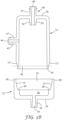
- Contactor 10 generally includes a cap 12, a cup body 14, and membrane cartridge 16.
- the membrane cartridge 16 may be located within the cup body 14.
- the cap 12 and cup body 14 are sealingly joined by joint 13 along joining surfaces 13' and 13".
- Surface 13' may be an internally facing joining surface located on cap 12, and surface 13" may be an externally facing joining surface located on cup body 14.
- the joint 13 is illustrated as a scarf joint (i.e., surfaces 13' and 13" are beveled), but joint 13 may be a shear joint (i.e., surfaces 13' and 13" are parallel to the axis of the contactor 10), or a butt joint or any other combination of joint designs.
- the contactor 10 will be illustrated with the scarf joint, but the shear joint may be used in place thereof.
- Cap 12 may be generally cup shaped (e.g., circular cross-section) with an open end 18 and a closed end 20, see Figure 3B .
- Cap 12 may also include an internally beveled surface 13', a shoulder 26, a skirt 28, a headspace 30, and a cap port 32 with an opening 34 therethrough.
- Cap port 32 may be a nipple extending away from cap 12.
- Beveled surface 13' may have a shallow angle, for example ⁇ 30°, or 4°-15°.
- Skirt 28 extends beyond joint 13, thereby concealing joint 13.
- Nipple is a sealable fitting, for example - a Luer (or medical) fitting, NPT, straight tube, compression, quick-connect, or any other suitable fitting.
- Cup body 14 may be generally cup shaped (e.g., circular cross-section) with an open end 36 and a closed end 38, see Figure 3B .
- Cup body 14 may also include an externally beveled surface 13", a shoulder 40, a side port 42 with an opening 44 therethrough, and end port 46 with an opening 48 therethrough.
- Beveled surface 13" may complement the angle of beveled surface 13'.
- Side port 42 may be a nipple 47 extending away from the cup body 14.
- End port 46 may include a nipple extending away from the cup body 14.
- End port 46 also includes an inwardly extending nipple 50 with a mating external surface 52. Mating external surface 52 may be beveled.
- Mating external surface 52 may have a shallow angle, for example ⁇ 30°, or 4°-15°.
- Nipple is a sealable fitting, for example - a Luer (or medical) fitting, NPT, straight tube, compression, quick-connect, or any other suitable fitting.
- Membrane cartridge 16 generally includes a bundle of membranes (e.g., hollow fiber membranes) 54 surrounding and bonded to a perforated center tube 56, see Figure 3A .
- the cartridge 16 has a first end 58 and a second end 60.
- a plug 62 is disposed in the center tube 56 adjacent second end 60.
- a mating internal surface 64 is located at the first end of the perforated center tube 56 adjacent the first end 58. Mating internal surface 64 may be beveled. Mating internal surface 64 may complement the angle of mating external surface 52.
- the hollow fiber membranes of bundle 54 are closed at the first end 58 and open at the second end 60.
- the bundle 54 may be bonded to the center tube 56 by a potting material. Potting material (e.g., epoxy, polyurethane, thermoplastic polymer, and/or adhesive) may be formed into walls 66 at the first end 58 and the second end 60 of the cartridge 16.
- Potting material e.g., epoxy, polyurethane, thermoplastic
- FIG. 3C illustrates that cartridge 16 may be made two-at-a-time, cartridge 16A and 16B.
- the membrane are wound around the center tube 56, so that the end of the membranes are closed 58A and 58B.
- the membrane is a plurality of hollow fibers
- the hollow fibers may be knit into a fabric (the lateral edges of the fabric will have closed or looped over ends) and then wound around the center tube 56.
- the membranes may be joined to the center tube 56 in a conventional fashion, i.e., potting at 66A, 66A/B, and 66B.
- cartridge 16A and cartridge 16B are separated (e.g., cut apart) along line 68.
- Plugs 62 may be formed at the same time that the potting at 66A/B are formed.
- cartridge 16 When assembled, see Figure 3A , (or assembling), cartridge 16 is inserted into cup body 14 by engaging mating surface 64 of the center tube 56 with the mating surface 52 of the end port 46. These mating surfaces 52 and 64 must be held in sealing engagement when cartridge 16 is fixed to cup body 14. This sealing engagement may be accomplished by luer lock, press fit, interference fit, snap fit, threading, welding, and/or gluing. These mating surfaces 52 and 64 may be held in sealing engagement when cartridge 16 is fixed to cup body 14 by, for example, material 70 or a mechanism (not shown). The material 70 or the mechanism also seals the cartridge 16 and cup body 14 in fluid tight engagement. Material 70 may be any material conventionally known in the art. Such materials 70 include potting and/or glue.
- Such mechanisms include threading, clips, o-rings, snap fittings.
- gas entrained liquid enters contactor 10 via end port 46 and travels along center tube 56 until blocked by plug 62.
- the gas entrained liquid exits the perforated center tube 56 and travels radially across the external surfaces of the hollow fiber membranes, and exits contactor 10 via side port 42 (this path defines the shell side).
- Vacuum or vacuum/sweep gas are introduced via cap port 32 and are in fluid communication with the lumens of the hollow fibers via headspace 30 (this path defines the tube side).
- the entrained gas is drawn from the liquid across the membranes and exits via cap port 32.
Landscapes
- Chemical & Material Sciences (AREA)
- Chemical Kinetics & Catalysis (AREA)
- Engineering & Computer Science (AREA)
- Manufacturing & Machinery (AREA)
- Water Supply & Treatment (AREA)
- Separation Using Semi-Permeable Membranes (AREA)
- Degasification And Air Bubble Elimination (AREA)
Applications Claiming Priority (2)
| Application Number | Priority Date | Filing Date | Title |
|---|---|---|---|
| US201562182684P | 2015-06-22 | 2015-06-22 | |
| PCT/US2016/038328 WO2016209761A1 (en) | 2015-06-22 | 2016-06-20 | Single weld contactor |
Publications (3)
| Publication Number | Publication Date |
|---|---|
| EP3310464A1 EP3310464A1 (en) | 2018-04-25 |
| EP3310464A4 EP3310464A4 (en) | 2019-03-06 |
| EP3310464B1 true EP3310464B1 (en) | 2025-02-12 |
Family
ID=57585462
Family Applications (1)
| Application Number | Title | Priority Date | Filing Date |
|---|---|---|---|
| EP16815105.8A Active EP3310464B1 (en) | 2015-06-22 | 2016-06-20 | Single weld contactor |
Country Status (6)
| Country | Link |
|---|---|
| US (1) | US10610831B2 (enExample) |
| EP (1) | EP3310464B1 (enExample) |
| JP (1) | JP6838817B2 (enExample) |
| KR (1) | KR102645537B1 (enExample) |
| CN (1) | CN107810045B (enExample) |
| WO (1) | WO2016209761A1 (enExample) |
Families Citing this family (2)
| Publication number | Priority date | Publication date | Assignee | Title |
|---|---|---|---|---|
| US10729991B2 (en) * | 2015-06-22 | 2020-08-04 | 3M Innovative Properties Company | Compact cross-flow contactor |
| US20190030459A1 (en) * | 2017-07-25 | 2019-01-31 | Hamilton Sundstrand Corporation | Fluid degassing systems |
Family Cites Families (13)
| Publication number | Priority date | Publication date | Assignee | Title |
|---|---|---|---|---|
| JPS57159502A (en) * | 1981-03-26 | 1982-10-01 | Toyobo Co Ltd | Separation membrane apparatus |
| WO1984002478A1 (en) * | 1982-12-20 | 1984-07-05 | Baxter Travenol Lab | End closure for tubular housing |
| JPH01151908A (ja) * | 1987-09-29 | 1989-06-14 | Teijin Ltd | 中空糸型流体処理器 |
| DE69022502T2 (de) * | 1989-02-09 | 1996-05-02 | Dow Chemical Co | Membrantrennvorrichtung und verfahren zur herstellung. |
| US5059374A (en) * | 1989-02-09 | 1991-10-22 | The Dow Chemical Company | Method for sealing a hollow fiber membrane module in a case |
| JP2001246232A (ja) * | 2000-03-03 | 2001-09-11 | Japan Gore Tex Inc | ガス透過膜装置 |
| US7264725B2 (en) * | 2004-03-04 | 2007-09-04 | Celgard Inc. | Hollow fiber membrane contactor and method of making same |
| US7638049B2 (en) * | 2004-03-30 | 2009-12-29 | Celgard Inc. | Three-port high performance mini hollow fiber membrane contactor |
| US20060081524A1 (en) | 2004-10-15 | 2006-04-20 | Amitava Sengupta | Membrane contactor and method of making the same |
| US7338601B2 (en) * | 2004-12-10 | 2008-03-04 | Uop Llc | Membrane separation assemblies |
| US7628916B2 (en) * | 2005-01-26 | 2009-12-08 | Celgard Llc | Hollow fiber module |
| US7641795B2 (en) | 2006-06-05 | 2010-01-05 | Celgard Llc | Membrane contactor |
| CN104226116B (zh) * | 2014-07-01 | 2016-06-22 | 杭州求是膜技术有限公司 | 一种膜接触器及其制造工艺 |
-
2016
- 2016-06-20 CN CN201680037024.1A patent/CN107810045B/zh active Active
- 2016-06-20 WO PCT/US2016/038328 patent/WO2016209761A1/en not_active Ceased
- 2016-06-20 EP EP16815105.8A patent/EP3310464B1/en active Active
- 2016-06-20 JP JP2017566334A patent/JP6838817B2/ja active Active
- 2016-06-20 KR KR1020187001076A patent/KR102645537B1/ko active Active
- 2016-06-20 US US15/560,040 patent/US10610831B2/en active Active
Also Published As
| Publication number | Publication date |
|---|---|
| US10610831B2 (en) | 2020-04-07 |
| JP6838817B2 (ja) | 2021-03-03 |
| KR102645537B1 (ko) | 2024-03-07 |
| EP3310464A4 (en) | 2019-03-06 |
| CN107810045B (zh) | 2021-04-09 |
| KR20180011326A (ko) | 2018-01-31 |
| US20180093226A1 (en) | 2018-04-05 |
| EP3310464A1 (en) | 2018-04-25 |
| CN107810045A (zh) | 2018-03-16 |
| WO2016209761A1 (en) | 2016-12-29 |
| JP2018518363A (ja) | 2018-07-12 |
Similar Documents
| Publication | Publication Date | Title |
|---|---|---|
| US7264725B2 (en) | Hollow fiber membrane contactor and method of making same | |
| US7638049B2 (en) | Three-port high performance mini hollow fiber membrane contactor | |
| KR100908992B1 (ko) | 분리 멤브레인 단부 캡 | |
| US8991027B2 (en) | Spiral wound filtration module | |
| KR101593341B1 (ko) | 스파이럴형 분리막 엘리먼트용 단부재, 스파이럴형 분리막 엘리먼트 및 분리막 모듈 | |
| EP3310464B1 (en) | Single weld contactor | |
| US20190105608A1 (en) | Hollow fiber membrane module and manufacturing method therefor | |
| WO2014017076A1 (ja) | スパイラル型正浸透膜エレメントおよび正浸透膜モジュール | |
| US20180133620A1 (en) | Compact cross-flow contactor | |
| JP2002361050A (ja) | 中空糸膜接触器とその製造方法 | |
| CN106237861B (zh) | 反渗透膜元件、反渗透膜元件的制备方法和滤芯 | |
| US20180021732A1 (en) | Membrane assembly with end cap device and related methods | |
| JPS58163404A (ja) | 流体分離装置 | |
| KR200419179Y1 (ko) | 수액기용 필터 캡 | |
| KR102680550B1 (ko) | 막 모듈 | |
| US20240157303A1 (en) | Dialyzer | |
| CN110508144B (zh) | 反渗透组件、反渗透过滤器和净水系统 | |
| US20220023801A1 (en) | Membrane element and process for making the same | |
| WO2017073279A1 (ja) | スパイラル型分離膜モジュール | |
| JP2019051463A (ja) | 集水構造 | |
| US20140021123A1 (en) | Adaptor and reverse osmosis apparatus using the same | |
| KR20150096856A (ko) | 중공사막 모듈 | |
| JP2007330946A (ja) | 液体分離装置 | |
| KR20160058571A (ko) | 멤브레인 모듈 제조용 레이저 가공 장치 | |
| JPH11333261A (ja) | カートリッジ式中空糸型膜モジュール |
Legal Events
| Date | Code | Title | Description |
|---|---|---|---|
| STAA | Information on the status of an ep patent application or granted ep patent |
Free format text: STATUS: THE INTERNATIONAL PUBLICATION HAS BEEN MADE |
|
| PUAI | Public reference made under article 153(3) epc to a published international application that has entered the european phase |
Free format text: ORIGINAL CODE: 0009012 |
|
| STAA | Information on the status of an ep patent application or granted ep patent |
Free format text: STATUS: REQUEST FOR EXAMINATION WAS MADE |
|
| 17P | Request for examination filed |
Effective date: 20171219 |
|
| AK | Designated contracting states |
Kind code of ref document: A1 Designated state(s): AL AT BE BG CH CY CZ DE DK EE ES FI FR GB GR HR HU IE IS IT LI LT LU LV MC MK MT NL NO PL PT RO RS SE SI SK SM TR |
|
| AX | Request for extension of the european patent |
Extension state: BA ME |
|
| DAV | Request for validation of the european patent (deleted) | ||
| DAX | Request for extension of the european patent (deleted) | ||
| A4 | Supplementary search report drawn up and despatched |
Effective date: 20190205 |
|
| RIC1 | Information provided on ipc code assigned before grant |
Ipc: B01D 61/00 20060101ALI20190130BHEP Ipc: B01D 19/00 20060101ALI20190130BHEP Ipc: B01D 69/08 20060101ALI20190130BHEP Ipc: C09D 11/00 20140101ALI20190130BHEP Ipc: B01D 63/02 20060101AFI20190130BHEP |
|
| STAA | Information on the status of an ep patent application or granted ep patent |
Free format text: STATUS: EXAMINATION IS IN PROGRESS |
|
| 17Q | First examination report despatched |
Effective date: 20211029 |
|
| RAP1 | Party data changed (applicant data changed or rights of an application transferred) |
Owner name: SOLVENTUM INTELLECTUAL PROPERTIES COMPANY |
|
| GRAP | Despatch of communication of intention to grant a patent |
Free format text: ORIGINAL CODE: EPIDOSNIGR1 |
|
| STAA | Information on the status of an ep patent application or granted ep patent |
Free format text: STATUS: GRANT OF PATENT IS INTENDED |
|
| INTG | Intention to grant announced |
Effective date: 20240909 |
|
| GRAS | Grant fee paid |
Free format text: ORIGINAL CODE: EPIDOSNIGR3 |
|
| GRAA | (expected) grant |
Free format text: ORIGINAL CODE: 0009210 |
|
| STAA | Information on the status of an ep patent application or granted ep patent |
Free format text: STATUS: THE PATENT HAS BEEN GRANTED |
|
| AK | Designated contracting states |
Kind code of ref document: B1 Designated state(s): AL AT BE BG CH CY CZ DE DK EE ES FI FR GB GR HR HU IE IS IT LI LT LU LV MC MK MT NL NO PL PT RO RS SE SI SK SM TR |
|
| REG | Reference to a national code |
Ref country code: GB Ref legal event code: FG4D |
|
| REG | Reference to a national code |
Ref country code: CH Ref legal event code: EP |
|
| REG | Reference to a national code |
Ref country code: DE Ref legal event code: R096 Ref document number: 602016091209 Country of ref document: DE |
|
| REG | Reference to a national code |
Ref country code: IE Ref legal event code: FG4D |
|
| REG | Reference to a national code |
Ref country code: NL Ref legal event code: MP Effective date: 20250212 |
|
| PG25 | Lapsed in a contracting state [announced via postgrant information from national office to epo] |
Ref country code: RS Free format text: LAPSE BECAUSE OF FAILURE TO SUBMIT A TRANSLATION OF THE DESCRIPTION OR TO PAY THE FEE WITHIN THE PRESCRIBED TIME-LIMIT Effective date: 20250512 |
|
| PG25 | Lapsed in a contracting state [announced via postgrant information from national office to epo] |
Ref country code: FI Free format text: LAPSE BECAUSE OF FAILURE TO SUBMIT A TRANSLATION OF THE DESCRIPTION OR TO PAY THE FEE WITHIN THE PRESCRIBED TIME-LIMIT Effective date: 20250212 |
|
| PG25 | Lapsed in a contracting state [announced via postgrant information from national office to epo] |
Ref country code: PL Free format text: LAPSE BECAUSE OF FAILURE TO SUBMIT A TRANSLATION OF THE DESCRIPTION OR TO PAY THE FEE WITHIN THE PRESCRIBED TIME-LIMIT Effective date: 20250212 |
|
| PGFP | Annual fee paid to national office [announced via postgrant information from national office to epo] |
Ref country code: DE Payment date: 20250520 Year of fee payment: 10 |
|
| PG25 | Lapsed in a contracting state [announced via postgrant information from national office to epo] |
Ref country code: ES Free format text: LAPSE BECAUSE OF FAILURE TO SUBMIT A TRANSLATION OF THE DESCRIPTION OR TO PAY THE FEE WITHIN THE PRESCRIBED TIME-LIMIT Effective date: 20250212 |
|
| REG | Reference to a national code |
Ref country code: LT Ref legal event code: MG9D |
|
| PG25 | Lapsed in a contracting state [announced via postgrant information from national office to epo] |
Ref country code: IS Free format text: LAPSE BECAUSE OF FAILURE TO SUBMIT A TRANSLATION OF THE DESCRIPTION OR TO PAY THE FEE WITHIN THE PRESCRIBED TIME-LIMIT Effective date: 20250612 Ref country code: NO Free format text: LAPSE BECAUSE OF FAILURE TO SUBMIT A TRANSLATION OF THE DESCRIPTION OR TO PAY THE FEE WITHIN THE PRESCRIBED TIME-LIMIT Effective date: 20250512 |
|
| PG25 | Lapsed in a contracting state [announced via postgrant information from national office to epo] |
Ref country code: NL Free format text: LAPSE BECAUSE OF FAILURE TO SUBMIT A TRANSLATION OF THE DESCRIPTION OR TO PAY THE FEE WITHIN THE PRESCRIBED TIME-LIMIT Effective date: 20250212 |
|
| PG25 | Lapsed in a contracting state [announced via postgrant information from national office to epo] |
Ref country code: HR Free format text: LAPSE BECAUSE OF FAILURE TO SUBMIT A TRANSLATION OF THE DESCRIPTION OR TO PAY THE FEE WITHIN THE PRESCRIBED TIME-LIMIT Effective date: 20250212 |
|
| PG25 | Lapsed in a contracting state [announced via postgrant information from national office to epo] |
Ref country code: LV Free format text: LAPSE BECAUSE OF FAILURE TO SUBMIT A TRANSLATION OF THE DESCRIPTION OR TO PAY THE FEE WITHIN THE PRESCRIBED TIME-LIMIT Effective date: 20250212 Ref country code: PT Free format text: LAPSE BECAUSE OF FAILURE TO SUBMIT A TRANSLATION OF THE DESCRIPTION OR TO PAY THE FEE WITHIN THE PRESCRIBED TIME-LIMIT Effective date: 20250612 |
|
| PG25 | Lapsed in a contracting state [announced via postgrant information from national office to epo] |
Ref country code: BG Free format text: LAPSE BECAUSE OF FAILURE TO SUBMIT A TRANSLATION OF THE DESCRIPTION OR TO PAY THE FEE WITHIN THE PRESCRIBED TIME-LIMIT Effective date: 20250212 Ref country code: GR Free format text: LAPSE BECAUSE OF FAILURE TO SUBMIT A TRANSLATION OF THE DESCRIPTION OR TO PAY THE FEE WITHIN THE PRESCRIBED TIME-LIMIT Effective date: 20250513 |
|
| REG | Reference to a national code |
Ref country code: AT Ref legal event code: MK05 Ref document number: 1765569 Country of ref document: AT Kind code of ref document: T Effective date: 20250212 |
|
| PG25 | Lapsed in a contracting state [announced via postgrant information from national office to epo] |
Ref country code: SE Free format text: LAPSE BECAUSE OF FAILURE TO SUBMIT A TRANSLATION OF THE DESCRIPTION OR TO PAY THE FEE WITHIN THE PRESCRIBED TIME-LIMIT Effective date: 20250212 |
|
| PG25 | Lapsed in a contracting state [announced via postgrant information from national office to epo] |
Ref country code: SM Free format text: LAPSE BECAUSE OF FAILURE TO SUBMIT A TRANSLATION OF THE DESCRIPTION OR TO PAY THE FEE WITHIN THE PRESCRIBED TIME-LIMIT Effective date: 20250212 |
|
| PG25 | Lapsed in a contracting state [announced via postgrant information from national office to epo] |
Ref country code: DK Free format text: LAPSE BECAUSE OF FAILURE TO SUBMIT A TRANSLATION OF THE DESCRIPTION OR TO PAY THE FEE WITHIN THE PRESCRIBED TIME-LIMIT Effective date: 20250212 |
|
| PG25 | Lapsed in a contracting state [announced via postgrant information from national office to epo] |
Ref country code: IT Free format text: LAPSE BECAUSE OF FAILURE TO SUBMIT A TRANSLATION OF THE DESCRIPTION OR TO PAY THE FEE WITHIN THE PRESCRIBED TIME-LIMIT Effective date: 20250212 |
|
| PG25 | Lapsed in a contracting state [announced via postgrant information from national office to epo] |
Ref country code: AT Free format text: LAPSE BECAUSE OF FAILURE TO SUBMIT A TRANSLATION OF THE DESCRIPTION OR TO PAY THE FEE WITHIN THE PRESCRIBED TIME-LIMIT Effective date: 20250212 |
|
| PG25 | Lapsed in a contracting state [announced via postgrant information from national office to epo] |
Ref country code: EE Free format text: LAPSE BECAUSE OF FAILURE TO SUBMIT A TRANSLATION OF THE DESCRIPTION OR TO PAY THE FEE WITHIN THE PRESCRIBED TIME-LIMIT Effective date: 20250212 Ref country code: CZ Free format text: LAPSE BECAUSE OF FAILURE TO SUBMIT A TRANSLATION OF THE DESCRIPTION OR TO PAY THE FEE WITHIN THE PRESCRIBED TIME-LIMIT Effective date: 20250212 |
|
| PG25 | Lapsed in a contracting state [announced via postgrant information from national office to epo] |
Ref country code: RO Free format text: LAPSE BECAUSE OF FAILURE TO SUBMIT A TRANSLATION OF THE DESCRIPTION OR TO PAY THE FEE WITHIN THE PRESCRIBED TIME-LIMIT Effective date: 20250212 |
|
| PG25 | Lapsed in a contracting state [announced via postgrant information from national office to epo] |
Ref country code: SK Free format text: LAPSE BECAUSE OF FAILURE TO SUBMIT A TRANSLATION OF THE DESCRIPTION OR TO PAY THE FEE WITHIN THE PRESCRIBED TIME-LIMIT Effective date: 20250212 |