EP3310139B1 - Baugruppenträger - Google Patents
Baugruppenträger Download PDFInfo
- Publication number
- EP3310139B1 EP3310139B1 EP16193230.6A EP16193230A EP3310139B1 EP 3310139 B1 EP3310139 B1 EP 3310139B1 EP 16193230 A EP16193230 A EP 16193230A EP 3310139 B1 EP3310139 B1 EP 3310139B1
- Authority
- EP
- European Patent Office
- Prior art keywords
- air
- power supply
- supply unit
- installation space
- fan
- Prior art date
- Legal status (The legal status is an assumption and is not a legal conclusion. Google has not performed a legal analysis and makes no representation as to the accuracy of the status listed.)
- Active
Links
- 238000009434 installation Methods 0.000 claims description 39
- 239000002699 waste material Substances 0.000 claims 2
- 238000001816 cooling Methods 0.000 description 13
- 238000009423 ventilation Methods 0.000 description 3
- 238000012423 maintenance Methods 0.000 description 2
- 238000005192 partition Methods 0.000 description 2
- 230000007547 defect Effects 0.000 description 1
- 239000002184 metal Substances 0.000 description 1
- 238000012544 monitoring process Methods 0.000 description 1
- 239000013589 supplement Substances 0.000 description 1
- 239000002918 waste heat Substances 0.000 description 1
Images


Classifications
-
- H—ELECTRICITY
- H05—ELECTRIC TECHNIQUES NOT OTHERWISE PROVIDED FOR
- H05K—PRINTED CIRCUITS; CASINGS OR CONSTRUCTIONAL DETAILS OF ELECTRIC APPARATUS; MANUFACTURE OF ASSEMBLAGES OF ELECTRICAL COMPONENTS
- H05K7/00—Constructional details common to different types of electric apparatus
- H05K7/20—Modifications to facilitate cooling, ventilating, or heating
- H05K7/20709—Modifications to facilitate cooling, ventilating, or heating for server racks or cabinets; for data centers, e.g. 19-inch computer racks
- H05K7/20718—Forced ventilation of a gaseous coolant
- H05K7/20727—Forced ventilation of a gaseous coolant within server blades for removing heat from heat source
-
- H—ELECTRICITY
- H05—ELECTRIC TECHNIQUES NOT OTHERWISE PROVIDED FOR
- H05K—PRINTED CIRCUITS; CASINGS OR CONSTRUCTIONAL DETAILS OF ELECTRIC APPARATUS; MANUFACTURE OF ASSEMBLAGES OF ELECTRICAL COMPONENTS
- H05K7/00—Constructional details common to different types of electric apparatus
- H05K7/20—Modifications to facilitate cooling, ventilating, or heating
- H05K7/20536—Modifications to facilitate cooling, ventilating, or heating for racks or cabinets of standardised dimensions, e.g. electronic racks for aircraft or telecommunication equipment
- H05K7/20554—Forced ventilation of a gaseous coolant
- H05K7/20572—Forced ventilation of a gaseous coolant within cabinets for removing heat from sub-racks, e.g. plenum
- H05K7/20581—Cabinets including a drawer for fans
-
- H—ELECTRICITY
- H05—ELECTRIC TECHNIQUES NOT OTHERWISE PROVIDED FOR
- H05K—PRINTED CIRCUITS; CASINGS OR CONSTRUCTIONAL DETAILS OF ELECTRIC APPARATUS; MANUFACTURE OF ASSEMBLAGES OF ELECTRICAL COMPONENTS
- H05K7/00—Constructional details common to different types of electric apparatus
- H05K7/20—Modifications to facilitate cooling, ventilating, or heating
- H05K7/20009—Modifications to facilitate cooling, ventilating, or heating using a gaseous coolant in electronic enclosures
- H05K7/20136—Forced ventilation, e.g. by fans
- H05K7/20145—Means for directing air flow, e.g. ducts, deflectors, plenum or guides
-
- H—ELECTRICITY
- H05—ELECTRIC TECHNIQUES NOT OTHERWISE PROVIDED FOR
- H05K—PRINTED CIRCUITS; CASINGS OR CONSTRUCTIONAL DETAILS OF ELECTRIC APPARATUS; MANUFACTURE OF ASSEMBLAGES OF ELECTRICAL COMPONENTS
- H05K7/00—Constructional details common to different types of electric apparatus
- H05K7/20—Modifications to facilitate cooling, ventilating, or heating
- H05K7/20709—Modifications to facilitate cooling, ventilating, or heating for server racks or cabinets; for data centers, e.g. 19-inch computer racks
- H05K7/20718—Forced ventilation of a gaseous coolant
- H05K7/20736—Forced ventilation of a gaseous coolant within cabinets for removing heat from server blades
Definitions
- the invention relates to a rack for the installation of electronic cards with standardized board format, for example, according to the PICMG standard "Advanced Telecom Computing Architecture (ATCA)" for powerful communication server. It is a scalable powerful architecture, which is characterized by a high functional density in a small footprint.
- ATCA Advanced Telecom Computing Architecture
- An ATCA subrack includes electrical fans located below or above the installation space. Cool air from the environment is sucked through openings on the front of the housing and directed into the installation space, where it sweeps past the electronic boards to cool them. The heated exhaust air is then blown out through openings in the back of the housing.
- the electric fans are usually combined to form a horizontal fan unit, which can be pulled out of the housing for maintenance and repair purposes.
- the server systems comprising a number of electronic boards and the fans or fan trays required for cooling are supplied with electrical energy by means of separate subassemblies or inserts.
- the Power Units provide the entire system with power, with the operating voltages being continuously measured and monitored in cooperation with one or more shelf managers.
- the power supply units which are also designed to be twice or more redundant in larger systems, require additional space, in particular height, which in turn is not available as an installation space for electronic cards.
- US 8,514,571 B2 describes a rack for horizontal installation of electronic cards (horizontal sub-rack).
- a ventilation box is arranged above and below an installation space for printed circuit boards.
- This box is divided by a partition into a right and a left chamber, namely an air inlet chamber for cool supply air and an air outlet chamber for heated exhaust air.
- An air inlet for cold supply air is provided on the front side and an air outlet for the heated exhaust air on the rear side.
- Behind the air intake sits a fan unit with several electric fans.
- Right and left of the installation space air spaces are provided, namely a Heilverteilraum for incoming cold air and an air collection chamber for heated air. These airspaces are in communication with the inlet chamber or the outlet chamber of the ventilation box.
- US 6 563 706 B1 describes a power supply module for a power bus.
- a power source and at least one fan for cooling the power source are mounted on a power supply module.
- the fans are supplied with voltage from the busbar.
- the technical problem to be solved is in the conflict of objectives, in a rack of predetermined size, in particular with a certain standardized height to provide the largest possible installation space for electronic cards available, but at the same time a sufficient number of electric fans for effective cooling and the necessary Supply power for the entire system.
- the fan tray contains not only electric fans, but also at least one power supply unit as an integrated part.
- the height "lost" anyway for the fan tray is thus used according to the invention for accommodating a power supply unit which would otherwise cost additional installation space.
- the total height of the subrack, which is completely equipped with electronic cards, fans and power supply, is reduced considerably, at least by the height of a power supply unit.
- the fan unit according to the invention is designed as a replaceable drawer in the manner of a drawer, the necessary accessibility to the integrated power supply unit is ensured at any time In the event of a defect or for maintenance, the fan drawer can be simply integrated PSU are pulled out of the housing to get to the power supply unit.
- the housing compartment which houses the fan unit must be divided into an air inlet chamber for cold supply air and an air outlet chamber for heated exhaust air. This is preferably carried out in that the fan tray has a rear wall, which serves as a room divider or separator.
- the fan tray a floor plan in the form of a right triangle, the hypotenuse is formed by the rear wall. This results in approximately triangular and approximately equal chambers for air inlet and outlet.
- the integrated in the fan tray power supply unit is preferably arranged in the air inlet chamber, so that it is in the flow of cold supply air. Particularly advantageous is the arrangement of the power supply unit in the region of the rear wall of the Ldorfereinschubs because it barely obstructs the cooling air flow there. If the power supply unit has a housing in the form of a narrow rectangular cuboid, it is expedient to arrange the power supply unit with a longitudinal side parallel to the rear wall of the fan module. It when the housing of the power supply unit is attached to the rear wall of the fan tray is particularly advantageous. The power supply unit then forms part of the air duct for the cooling air or an integral part of the partition between the air inlet chamber and the air outlet chamber.
- the power supply unit usually has itself a small electric fan, which is installed in the housing.
- the power supply unit according to the invention is an integral part of the fan tray, it is expedient to arrange the power supply unit so that the air flow of the built-in electric fan parallel to the main air flow the cooling air flowing into the air inlet chamber runs. Main and secondary air flow are then rectified and supplement or reinforce thereby. Should it come to the failure of one or even all fans of the fan unit, the independent cooling of the power supply remains independent and can, to a certain extent, serve as emergency cooling for the electronic boards. Conversely, a failure of the self-cooling of the power supply through the cooling air flow through the air inlet chamber would be at least partially compensated, which increases the reliability.
- fan trays with integrated power supply units can be provided both above and below the installation space for electronic cards.
- the air inlet openings of the two fan trays are expediently on the same side, usually at the front of the rack. Accordingly blow both fan trays the heated exhaust air on the opposite side of the rack, ie on the back of.
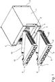
- Subrack shown is an Advanced TCA system with a housing 1, which surrounds an installation space 2 for standardized electronic boards on all sides. Reflective outwardly facing mounting flanges 3 on the front of the housing 1 are for installation in a 19-inch rack or in a 23-inch Telecom shelf. The (not shown here) cards or boards with the active electronic components are inserted horizontally into the installation space 2; So this is a "horizontal sub-rack”.
- a compartment 4 is arranged in each case.
- the horizontal shelves 5 of these compartments 4 limit the installation space 2 up or down.
- the bottom and the lid of the housing 1 close the compartments 4 downwards or upwards. To the back of the housing 1 through the compartments 4 are open.
- each a fan tray 6 can be inserted.
- FIG. 1 the two fan trays 6 are pulled out.
- the fan trays 6 sit in the compartments 4, the front sides 7 of the fan trays 6 are flush with the back of the housing 1.
- five air outlet openings 8 are arranged behind each of which an electric fan 9 is located.
- the fan trays 6 are formed as a substantially closed cassettes made of sheet metal and have a floor plan in the form of a right triangle.
- the hypotenuse of this triangle is formed by the rear wall 10 of the fan tray 6.
- the side walls 11 have large rectangular air inlets 12 through which cooling air can flow into the installation space 2.
- the power supply unit 13 has a housing in the form of a narrow rectangular cuboid and extends with its longitudinal side parallel to the rear wall 10 of the associated fan tray. 6
- the power supply unit 13 forms an integral part of the associated fan tray 6.
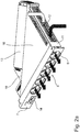
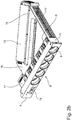
- FIGS. 2a and 2 B let see more details of the Ldorfereinschübe 6 with mounted power supply unit 13.
- FIG. 2b is the triangular cover 16 of the fan tray 6 removed. This frees the view into the interior.
- a network connection 14 is arranged next to the round air outlet openings 8.
- the fans 9 which are arranged behind the air outlet openings 8 are axial fans which generate a negative pressure at their rear side, pull the cold supply air through the installation space 2 and blow the heated exhaust air through the air outlet openings 8 into the environment.
- a compact electronic control unit 17 Behind the mains connection 14 sits a compact electronic control unit 17. In the area in front of the rear wall 10 sits a control board 18 which contains further electronic modules for controlling and monitoring the system.
- the rear wall 10 of the Lsymmetricereinschubs with anmontierter power supply unit 13 serves as a virtually airtight separating element between an air inlet chamber 20 and an air outlet chamber 21 side of the installation space 2 is a vertical Heilverteilschacht 22, which connects the air inlet chamber 20 with the installation space 2.
- an air collecting shaft 23 is provided, which connects the installation space 2 with the air outlet chamber 21.
- the cold air K drawn by the fans 9 of the upper fan tray 6 flows through inlet openings (not shown) at the front of the housing 1 into the air inlet chamber 20.
- the power supply unit 13 extends parallel to the main air flow;
- the built-in fan generates a - comparatively small - second air flow, which runs parallel to the main air flow of the incoming into the air inlet chamber 20 cold air K.
- the thus heated air is passed through the air collecting shaft 23 on the other side of the installation space 2 back up and collects as warm exhaust air W in the air outlet chamber 21.
- the air outlet 8 at the back of the housing 1 the heated exhaust air W is blown out.
Landscapes
- Engineering & Computer Science (AREA)
- Microelectronics & Electronic Packaging (AREA)
- Physics & Mathematics (AREA)
- Thermal Sciences (AREA)
- Computer Hardware Design (AREA)
- General Engineering & Computer Science (AREA)
- Aviation & Aerospace Engineering (AREA)
- Cooling Or The Like Of Electrical Apparatus (AREA)
Description
- Die Erfindung betrifft einen Baugruppenträger zum Einbau von Elektronikkarten mit standardisiertem Platinenformat, beispielsweise nach dem PICMG-Standard "Advanced Telecom Computing Architecture (ATCA)" für leistungsfähige Kommunikationsserver. Es handelt sich hierbei um eine skalierbare leistungsfähige Architektur, die sich durch eine hohe Funktionsdichte bei geringem Platzbedarf auszeichnet.
- Wird eine größere Anzahl von Platinen mit vielen elektronischen Komponenten oder Modulen in einen relativ kleinen Baugruppenträger gepackt, kommt dem Wärme-Management besondere Bedeutung zu, da entsprechend viel Verlustwärme von den Elektronikplatinen abgeführt werden muss. Nach der Spezifikation PICMG 3.0 sind bis zu 450 Watt pro ATCA-Board zulässig, was bei einem Baugruppenträger mit 14 Einbauplätzen (slots) einer abzuführenden Wärme von über 6 Kilowatt entspricht.
- Zu einem ATCA-Baugruppenträger gehören elektrische Lüfter, die sich unterhalb oder oberhalb des Einbauraums befinden. Kühle Luft aus der Umgebung wird dabei durch Öffnungen an der Gehäusefront angesaugt und in den Einbauraum geleitet, wo sie an den Elektronikplatinen vorbei streicht, um diese zu kühlen. Die erwärmte Abluft wird anschließend durch Öffnungen an der Rückseite des Gehäuses ausgeblasen. Die elektrischen Lüfter werden üblicherweise zu einem horizontalen Lüftereinschub zusammengefasst, welcher zu Wartungs- und Reparaturzwecken aus dem Gehäuse herausgezogen werden kann.
- Es ist klar, dass eine leistungsfähige Lüftung einschließlich der zugehörigen Luftverteilräume relativ viel Platz im Baugruppenträger beansprucht. Dies begrenzt den für den Einbau von Elektronikplatinen verbleibenden Einbauraum, insbesondere die aktiv nutzbare Höhe.
- Die eine Anzahl von Elektronikplatinen und die zur Kühlung erforderlichen Lüfter bzw. Lüftereinschübe umfassenden Serversysteme werden mittels separaten Unterbaugruppen oder Einschüben mit elektrischer Energie versorgt. Die Power-Units (PSU) versorgen das Gesamtsystem mit Strom, wobei die Betriebsspannungen laufend gemessen und überwacht werden, in Kooperation mit einem oder mehreren Shelf-Managern. Die Stromversorgungseinheiten, die bei größeren Systemen auch gerne doppelt oder mehrfach redundant ausgeführt werden, benötigen weiteren Platz, insbesondere Höhe, welche wiederum nicht als Einbauraum für Elektronikkarten zur Verfügung steht.
-
US 8,514,571 B2 beschreibt einen Baugruppenträger für horizontalen Einbau von Elektronikkarten (horizontal sub-rack). Über und unter einem Einbauraum für Leiterplatten ist eine Lüftungsbox angeordnet. Diese Box wird durch eine Trennwand in eine rechte und eine linke Kammer geteilt, nämlich eine Lufteintritts-Kammer für kühle Zuluft und eine Luftaustritts-Kammer für erwärmte Abluft. An der Vorderseite ist ein Lufteintritt für kalte Zuluft, an der Rückseite ein Luftaustritt für die erwärmte Abluft vorgesehen. Hinter dem Lufteintritt sitzt eine Lüftereinheit mit mehreren elektrischen Ventilatoren. Rechts und links des Einbauraums sind Lufträume vorgesehen, nämlich ein Luftverteilraum für einströmende Kaltluft und ein Luftsammelraum für erwärmte Luft. Diese Lufträume stehen mit der Einlasskammer bzw. der Auslasskammer der Lüftungsbox In Verbindung. Somit kann Frischluft aus der Umgebung durch den Einlass angesaugt und nach unten In den Luftverteilraum gedrückt werden ("push").Die Kaltluft wird um 90 Grad In die Horizontale gelenkt, strömt durch den Einbauraum hindurch und sammelt sich als erwärmte Luft In dem Luftsammelraum auf der anderen Seite. Von dort wird die Warmluft nach oben In die Luftauslass-Kammer gedrückt und entweicht schließlich durch den Luft- -
US 6 563 706 B1 beschreibt ein Stromversorgungsmodul für eine Stromschiene (power bus). Dabei sind auf einem Stromversorgungsmodul jeweils eine Stromquelle und mindestens ein Lüfter zur Kühlung der Stromquelle angebracht. Die Lüfter werden mit Spannung von der Stromschiene versorgt. - Das zu lösende technische Problem besteht In dem Zielkonflikt, in einem Baugruppenträger vorgegebener Größe, Insbesondere mit einer bestimmten standardisierten Höhe, einen möglichst großen Einbauraum für Elektronikkarten zur Verfügung zu stellen, gleichzeitig aber auch eine ausreichende Anzahl von elektrischen Lüftern für eine wirksame Kühlung sowie die notwendige Stromversorgung für das Gesamtsystem unterzubringen.
- Bei der Lösung dieser Aufgabe wird ausgegangen von einem Baugruppenträger gemäß dem Oberbegriff des ersten Patentanspruchs. Gelöst wird die Aufgabe gemäß dem kennzeichnenden Teil des Patentanspruchs 1 dadurch, dass der Lüftereinschub nicht nur elektrische Lüfter enthält, sondern auch mindestens eine Stromversorgungseinheit als integrierten Bestandteil. Die für den Lüftereinschub ohnehin "verlorene" Höhe wird also erfindungsgemäß benutzt für die Unterbringung einer Stromversorgungseinheit, die ansonsten zusätzlichen Einbauraum kosten würde. Die Gesamthöhe des komplett mit Elektronikkarten, Lüftern und Stromversorgung bestückten Baugruppenträgers wird erheblich reduziert, mindestens um die Höhe einer Stromversorgungseinheit.
- Da erfindungsgemäß die Lüftereinheit als tauschbarer Einschub in der Art einer Schublade ausgebildet ist, ist die notwendige Zugänglichkeit zu der integrierten Stromversorgungseinheit jederzeit gewährleistet Bei einem Defekt oder zu Wartungszwecken kann einfach der Lüftereinschub mit der integrierten PSU aus dem Gehäuse herausgezogen werden, um an die Stromversorgungseinheit zu gelangen.
- Um die Lufteinlassöffnungen und die Luftauslassöffnungen auf gleicher Höhe anzuordnen, muss das Gehäusefach, das den Lüftereinschub aufnimmt, in eine Lufteingangskammer für kalte Zuluft und eine Luftausgangskammer für erwärmte Abluft geteilt werden. Dies erfolgt vorzugsweise dadurch, dass der Lüftereinschub eine Rückwand hat, die als Raumteiler bzw. Trennelement dient.
- Besonders vorteilhaft hat der Lüftereinschub einen Grundriss in Form eines rechtwinkligen Dreiecks, dessen Hypotenuse durch die Rückwand gebildet wird. Es entstehen dadurch annähernd dreieckige und etwa gleichgroße Kammern für Lufteingang und Luftausgang.
- Die in den Lüftereinschub integrierte Stromversorgungseinheit ist vorzugsweise in der Lufteingangskammer angeordnet, so dass sie im Strom der kalten Zuluft liegt. Besonders vorteilhaft ist die Anordnung der Stromversorgungseinheit im Bereich der Rückwand des Lüftereinschubs, da sie dort den Kühlluftstrom kaum behindert. Sofern die Stromversorgungseinheit ein Gehäuse in Form eines schmalen rechteckigen Quaders hat, ist es zweckmäßig, die Stromversorgungseinheit mit einer Längsseite parallel zur Rückwand des Lüftereinschubs anzuordnen. Besonders vorteilhaft ist es, wenn das Gehäuse der Stromversorgungseinheit an der Rückwand des Lüftereinschubs befestigt ist. Die Stromversorgungseinheit bildet dann einen Teil der Luftführung für die Kühlluft bzw. ein integrierter Bestandteil des Trennelements zwischen Lufteingangskammer und Luftausgangskammer.
- Die Stromversorgungseinheit hat üblicherweise selbst einen kleinen elektrischen Lüfter, der in das Gehäuse eingebaut ist. Wenn nun die Stromversorgungseinheit erfindungsgemäß integrierter Bestandteil des Lüftereinschubs ist, so ist es zweckmäßig, die Stromversorgungseinheit so anzuordnen, dass der Luftstrom des eingebauten elektrischen Lüfters parallel zum Hauptluftstrom der in die Lufteingangskammer einströmenden Kühlluft verläuft. Haupt- und Nebenluftstrom sind dann gleichgerichtet und ergänzen bzw. verstärken sich dadurch. Sollte es zum Ausfall eines oder gar aller Lüfter des Lüftereinschubs kommen, so bleibt die davon unabhängige Eigenkühlung der Stromversorgung erhalten und kann, bis zu einem gewissen Grad, als Notkühlung für die Elektronikplatinen dienen. Umgekehrt würde auch ein Ausfall der Eigenkühlung der Stromversorgung durch den Kühlluftstrom durch die Lufteingangskammer zumindest teilweise kompensiert werden, was die Ausfallsicherheit erhöht.
- Bei höheren Baugruppenträgern mit einem Einbauraum für eine größere Anzahl von Elektronikplatinen können Lüftereinschübe mit integrierten Stromversorgungseinheiten sowohl über als auch unterhalb des Einbauraums für Elektronikkarten vorgesehen werden. Dabei liegen die Lufteinlassöffnungen der beiden Lüftereinschübe zweckmäßigerweise auf derselben Seite, üblicherweise an der Vorderseite des Baugruppenträgers. Entsprechend blasen dann beide Lüftereinschübe die erwärmte Abluft an der gegenüberliegenden Seite des Baugruppenträgers, also an der Rückseite, aus.
- Ein Ausführungsbeispiel der Erfindung wird nachstehend anhand der beigefügten Abbildungen näher beschrieben. Es zeigen:
- Figur 1
- einen Baugruppenträger mit zwei herausgezogenen Lüftereinschüben, in perspektivischer Ansicht von hinten;
- Figur 2a
- einen Lüftereinschub aus
Figur 1 mit integrierter Stromversorgungseinheit, in größerem Maßstab; - Figur 2b
- den Lüftereinschub von
Figur 2a ohne Deckblech; - Figur 3a
- den Baugruppenträger von
Figur 1 mit eingesetzten Lüftereinschüben, teilweise geöffnet, in perspektivischer Ansicht von links; - Figur 3b
- den Baugruppenträger gemäß
Figur 3a , in perspektivischer Ansicht von rechts. - Bei dem in
Figur 1 dargestellten Baugruppenträger handelt es sich um ein Advanced TCA-System mit einem Gehäuse 1, das einen Einbauraum 2 für standardisierte Elektronikplatinen allseitig umgibt. Spiegelbildlich nach außen weisende Befestigungsflansche 3 an der Vorderseite des Gehäuses 1 dienen dem Einbau in ein 19-Zoll-Gestell oder in ein 23-Zoll-Telecom-Shelf. Die (hier nicht dargestellten) Karten oder Platinen mit den aktiven elektronischen Bauelementen werden horizontal in den Einbauraum 2 eingeschoben; es handelt sich hier also um ein "horizontal sub-rack". - Oberhalb und unterhalb des Einbauraums 2 ist jeweils ein Fach 4 angeordnet. Die horizontalen Fachböden 5 dieser Fächer 4 begrenzen den Einbauraum 2 nach oben bzw. unten. Boden und Deckel des Gehäuses 1 schließen die Fächer 4 nach unten bzw. nach oben hin ab. Zur Rückseite des Gehäuses 1 hin sind die Fächer 4 offen.
- In die offenen Fächer 4 kann jeweils ein Lüftereinschub 6 eingeschoben werden. In
Figur 1 sind die beiden Lüftereinschübe 6 herausgezogen. In eingeschobenem Zustand sitzen die Lüftereinschübe 6 in den Fächern 4, wobei die Frontseiten 7 der Lüftereinschübe 6 mit der Rückseite des Gehäuses 1 bündig abschließen. In den Frontseiten 7 der Lüftereinschübe 6 sind jeweils fünf Luftauslassöffnungen 8 angeordnet, hinter denen sich jeweils ein elektrischer Lüfter 9 befindet. - Die Lüftereinschübe 6 sind als im Wesentlichen geschlossene Kassetten aus Blech ausgebildet und haben einen Grundriss in Form eines rechtwinkligen Dreiecks. Die Hypotenuse dieses Dreiecks wird von der Rückwand 10 des Lüftereinschubs 6 gebildet. Die Seitenwände 11 haben große rechteckige Lufteinlässe 12, durch die Kühlluft in den Einbauraum 2 einströmen kann.
- An den Außenseiten der Rückwände 10 der Lüftereinschübe 6 ist jeweils eine Stromversorgungseinheit 13 befestigt. Die Stromversorgungseinheit 13 hat ein Gehäuse in Form eines schmalen rechteckigen Quaders und erstreckt sich mit ihrer Längsseite parallel zur Rückwand 10 des zugehörigen Lüftereinschubs 6.
- Somit bildet die Stromversorgungseinheit 13 einen integralen Bestandteil des zugehörigen Lüftereinschubs 6.
- Die
Figuren 2a und2b lassen weitere Details der Lüftereinschübe 6 mit angebauter Stromversorgungseinheit 13 erkennen. InFigur 2b ist das dreieckige Deckblech 16 des Lüftereinschubs 6 abgenommen. Dadurch wird der Blick in das Innere frei. - An der Frontseite 7 ist neben den runden Luftauslassöffnungen 8 ein Netzanschluss 14 angeordnet. Die jeweils hinter den Luftauslassöffnungen 8 angeordneten Lüfter 9 sind Axiallüfter, welche an ihrer Rückseite einen Unterdruck erzeugen, die kalte Zuluft durch den Einbauraum 2 ziehen ("pull") und die erwärmte Abluft durch die Luftauslassöffnungen 8 in die Umgebung blasen.
- Hinter dem Netzanschluss 14 sitzt eine kompakte elektronische Steuereinheit 17. Im Bereich vor der Rückwand 10 sitzt eine Steuerungsplatine 18, die weitere elektronische Module zur Regelung und Überwachung des Systems enthält.
- In den Abbildungen der
Figuren 3a und3b sind die Lüftereinschübe 6 in die Fächer 4 des Gehäuses 1 eingeschoben. Jetzt wird erkennbar, wie die angesaugte Kühlluft durch das Innere des Gehäuses 1 strömt, um die Abwärme aus dem Einbauraum 2 wirksam abzuleiten. - Die Rückwand 10 des Lüftereinschubs mit anmontierter Stromversorgungseinheit 13 dient als praktisch luftdichtes Trennelement zwischen einer Lufteingangskammer 20 und einer Luftausgangskammer 21. Seitlich neben dem Einbauraum 2 liegt ein vertikaler Luftverteilschacht 22, der die Lufteingangskammer 20 mit dem Einbauraum 2 verbindet. An der gegenüberliegenden Seite des Einbauraums 2 ist ein Luftsammelschacht 23 vorgesehen, welcher den Einbauraum 2 mit der Luftausgangskammer 21 verbindet.
- Die von den Lüftern 9 des oberen Lüftereinschubs 6 angesaugte Kaltluft K strömt durch (nicht dargestellte) Eingangsöffnungen an der Vorderseite des Gehäuses 1 in die Lufteingangskammer 20. Die Stromversorgungseinheit 13 erstreckt sich parallel zum Hauptluftstrom; deren eingebauter Lüfter erzeugt dabei einen - vergleichsweise kleinen - zweiten Luftstrom, der parallel zum Hauptluftstrom der in die Lufteingangskammer 20 einströmenden Kaltluft K verläuft.
- Die eingeströmte Kaltluft K strömt durch den vertikalen Luftverteilschacht 22 nach unten wird nach Umlenkung um 90 Grad in den Einbauraum 2 geleitet, um an den dort eingebauten (nicht dargestellten) Elektronikplatinen vorbei zu streichen. Die dadurch erwärmte Luft wird durch den Luftsammelschacht 23 an der anderen Seite des Einbauraums 2 wieder nach oben geleitet und sammelt sich als warme Abluft W in der Luftausgangskammer 21. Durch die Luftauslassöffnungen 8 an der Rückseite des Gehäuses 1 wird die erwärmte Abluft W ausgeblasen.
- Unterhalb des Einbauraums 2 sitzt der zweite Lüftereinschub 6 (vgl.
Figur 1 ) hinter einem Luftgitter 24. Die deshalb hier nicht sichtbare Lufteingangskammer 20 des unteren Lüftereinschubs 6 ist mit demselben Luftverteilschacht 22 verbunden wie die Lufteingangskammer 20 des oberen Lüftereinschubs 6. Die Luftströme beider Lüftereinschübe 6 überlagern sich zu einem gemeinsamen Kühlluftstrom durch den Einbauraum 2. -
- 1
- Gehäuse
- 2
- Einbauraum
- 3
- Befestigungsflansch
- 4
- Fach
- 5
- Fachboden(von 1)
- 6
- Lüftereinschub
- 7
- Frontseite (von 6)
- 8
- Luftauslassöffnungen (in 7)
- 9
- Lüfter
- 10
- Rückwand (von 6)
- 11
- Seitenwand (von 6)
- 12
- Lufteinlass (in 11)
- 13
- Stromversorgungseinheit (PSU)
- 14
- Netzanschluss
- 16
- Deckblech (von 6)
- 17
- Steuerungseinheit
- 18
- Steuerungsplatine
- 20
- Lufteingangskammer
- 21
- Luftausgangskammer
- 22
- Luftverteilschacht
- 23
- Luftsammelschacht
- 24
- Luftgitter
- K
- Kalte Zuluft
- W
- Warme Abluft
Claims (9)
- Baugruppenträger, mit
einem Gehäuse (1), das einen Einbauraum (2) für standardisierte Elektronikplatinen einschließt,
wenigstens einem Lüftereinschub (6), der oberhalb oder unterhalb des Einbauraums (2) angeordnet ist und eine Anzahl von elektrischen Lüftern (9) enthält,
eine Lufteingangskammer (20) für kalte Zuluft (K) sowie eine Luftausgangskammer (21) für erwärmte Abluft (W),
einem seitlich neben dem Einbauraum (2) angeordneten Luftverteilschacht (22), der die Lufteingangskammer (20) mit dem Einbauraum (2) verbindet, um die kalte Zuluft (K) auf die Elektronikplatinen zu leiten,
einem an der gegenüberliegenden Seite des Einbauraums (2) angeordneten Luftsammelschacht (23), der den Einbauraum (2) mit der Luftausgangskammer (21) verbindet, um die erwärmte Abluft (W) abzuführen,
wenigstens einer Stromversorgungseinheit (13), welche die Elektronikplatinen und die Lüfter (9) mit elektrischer Energie versorgt,
dadurch gekennzeichnet, dass
der Lüftereinschub (6) in ein Fach (4) des Gehäuses (1) eingeschoben und herausziehbar ist, und
die Stromversorgungseinheit (13) integrierter Bestandteil des Lüftereinschubs (6) ist. - Baugruppenträger nach einem der vorhergehenden Ansprüche, dadurch gekennzeichnet, dass der Lüftereinschub (6) eine Rückwand (10) hat, welche die Lufteingangskammer (20) von der Luftausgangskammer (21) trennt.
- Baugruppenträger nach Anspruch 2, dadurch gekennzeichnet, dass der Lüftereinschub (6) einen Grundriss hat, der im Wesentlichen der Form eines rechtwinkligen Dreiecks entspricht, wobei die Rückwand (10) die Hypotenuse des Dreiecks bildet.
- Baugruppenträger nach Anspruch 2 oder 3, dadurch gekennzeichnet, dass die Stromversorgungseinheit (13) im Bereich der Rückwand (10) des Lüftereinschubs (6) angeordnet ist.
- Baugruppenträger nach Anspruch 4, dadurch gekennzeichnet, dass das Gehäuse der Stromversorgungseinheit (13) an der Rückwand (10) des Lüftereinschubs (6) befestigt ist.
- Baugruppenträger nach einem der Ansprüche 2 bis 5, dadurch gekennzeichnet, dass die Stromversorgungseinheit (13) ein Gehäuse in Form eines schmalen rechteckigen Quaders hat und mit einer Längsseite parallel zur Rückwand (10) des Lüftereinschubs (6) verläuft.
- Baugruppenträger nach einem der vorhergehenden Ansprüche, dadurch gekennzeichnet, dass die Stromversorgungseinheit (13) in der Lufteingangskammer (20) angeordnet ist, so dass sie im Strom der kalten Zuluft (K) liegt.
- Baugruppenträger nach Anspruch 7, dadurch gekennzeichnet, dass die Stromversorgungseinheit (13) einen eingebauten elektrischen Lüfter hat, dessen Luftstrom parallel zum Hauptluftstrom der in die Lufteingangskammer (21) einströmenden kalten Zuluft (K) verläuft.
- Baugruppenträger nach einem der vorhergehenden Ansprüche, dadurch gekennzeichnet, dass ein erster Lüftereinschub (6) mit integrierter Stromversorgungseinheit (13) über dem Einbauraum (2) angeordnet ist und ein zweiter, im Prinzip gleich ausgebildeter Lüftereinschub (6) mit integrierter Stromversorgungseinheit (13) unterhalb des Einbauraums (2) angeordnet ist, wobei die Luftauslassöffnungen (8) der beiden Lüftereinschübe (6) auf derselben Seite des Gehäuses (1) liegen.
Priority Applications (2)
| Application Number | Priority Date | Filing Date | Title |
|---|---|---|---|
| EP16193230.6A EP3310139B1 (de) | 2016-10-11 | 2016-10-11 | Baugruppenträger |
| US15/729,429 US10492336B2 (en) | 2016-10-11 | 2017-10-10 | Subrack assembly for electronic equipment |
Applications Claiming Priority (1)
| Application Number | Priority Date | Filing Date | Title |
|---|---|---|---|
| EP16193230.6A EP3310139B1 (de) | 2016-10-11 | 2016-10-11 | Baugruppenträger |
Publications (2)
| Publication Number | Publication Date |
|---|---|
| EP3310139A1 EP3310139A1 (de) | 2018-04-18 |
| EP3310139B1 true EP3310139B1 (de) | 2019-09-04 |
Family
ID=57123897
Family Applications (1)
| Application Number | Title | Priority Date | Filing Date |
|---|---|---|---|
| EP16193230.6A Active EP3310139B1 (de) | 2016-10-11 | 2016-10-11 | Baugruppenträger |
Country Status (2)
| Country | Link |
|---|---|
| US (1) | US10492336B2 (de) |
| EP (1) | EP3310139B1 (de) |
Cited By (1)
| Publication number | Priority date | Publication date | Assignee | Title |
|---|---|---|---|---|
| CN110621146A (zh) * | 2019-11-25 | 2019-12-27 | 深圳市科信通信技术股份有限公司 | 一种户外bbu集中柜 |
Families Citing this family (6)
| Publication number | Priority date | Publication date | Assignee | Title |
|---|---|---|---|---|
| US9832912B2 (en) * | 2015-05-07 | 2017-11-28 | Dhk Storage, Llc | Computer server heat regulation utilizing integrated precision air flow |
| CN108966598A (zh) * | 2018-08-02 | 2018-12-07 | 佛山鑫达智汇科技有限公司 | 电子计算设备 |
| DE102018127546B4 (de) | 2018-11-05 | 2020-08-06 | Intermas-Elcom Gmbh | Lüftereinschub |
| CN113133187B (zh) * | 2021-04-17 | 2022-01-18 | 深圳市三德冠精密电路科技有限公司 | 一种柔性电路板辅助散热机构 |
| US20230040718A1 (en) * | 2021-08-06 | 2023-02-09 | Commscope Technologies Llc | Rack mounting adapter with airflow management |
| CN113710032A (zh) * | 2021-08-31 | 2021-11-26 | 中国电子科技集团公司第十四研究所 | 一种耐磨机箱 |
Family Cites Families (18)
| Publication number | Priority date | Publication date | Assignee | Title |
|---|---|---|---|---|
| US6563706B1 (en) * | 1998-06-23 | 2003-05-13 | Hewlett-Packard Development Company, L.P. | Typically high-availability information storage product |
| US20030184968A1 (en) | 2002-04-01 | 2003-10-02 | White Rock Networks | Systems and methods for removable fans in a rack-mounted communications switch component |
| US6625033B1 (en) * | 2002-04-01 | 2003-09-23 | White Rock Networks | Systems and methods for a reducing EMI in a communications switch component utilizing overlapping interfaces |
| US6836030B2 (en) * | 2002-05-31 | 2004-12-28 | Verari Systems, Inc. | Rack mountable computer component power distribution unit and method |
| US6801428B2 (en) | 2002-05-31 | 2004-10-05 | Racksaver, Inc. | Rack mountable computer component fan cooling arrangement and method |
| US6819563B1 (en) * | 2003-07-02 | 2004-11-16 | International Business Machines Corporation | Method and system for cooling electronics racks using pre-cooled air |
| US7965504B2 (en) | 2006-05-25 | 2011-06-21 | Emerson Network Power—Embedded Computing, Inc. | Embedded computer chassis with redundant fan trays |
| US7492591B1 (en) | 2007-01-10 | 2009-02-17 | Juniper Networks, Inc. | Reversible airflow fan tray for an electronic device |
| TWM337947U (en) * | 2008-01-24 | 2008-08-01 | Alpha Networks Inc | Server device |
| CN101516166B (zh) | 2008-02-22 | 2010-12-08 | 华为技术有限公司 | 一种横插框及通信机柜 |
| JP4968630B2 (ja) | 2008-11-27 | 2012-07-04 | 株式会社デンソー | 電気自動車の制御装置 |
| US8116082B2 (en) * | 2009-11-17 | 2012-02-14 | Telefonaktiebolaget L M Ericsson (Publ) | Fan tray that is installable and removable from the front and back of a network element chassis |
| GB2506017B (en) * | 2011-05-25 | 2015-11-04 | Hewlett Packard Development Co | Blade computer system |
| US8780551B2 (en) * | 2011-12-21 | 2014-07-15 | Brocade Communications Systems, Inc. | Blade and air deflector in a plenum |
| US9839155B2 (en) * | 2012-05-16 | 2017-12-05 | Panduit Corp. | Thermal ducting system |
| US9204576B2 (en) * | 2012-09-14 | 2015-12-01 | Cisco Technolgy, Inc. | Apparatus, system, and method for configuring a system of electronic chassis |
| US9334879B2 (en) * | 2012-10-04 | 2016-05-10 | Cisco Technology, Inc. | Fan tray perforation pattern |
| US9661787B2 (en) * | 2015-06-29 | 2017-05-23 | Telefonaktiebolaget Lm Ericsson (Publ) | Facilitating front access to rear-mounted assembly in equipment chassis |
-
2016
- 2016-10-11 EP EP16193230.6A patent/EP3310139B1/de active Active
-
2017
- 2017-10-10 US US15/729,429 patent/US10492336B2/en active Active
Non-Patent Citations (1)
| Title |
|---|
| None * |
Cited By (2)
| Publication number | Priority date | Publication date | Assignee | Title |
|---|---|---|---|---|
| CN110621146A (zh) * | 2019-11-25 | 2019-12-27 | 深圳市科信通信技术股份有限公司 | 一种户外bbu集中柜 |
| CN110621146B (zh) * | 2019-11-25 | 2020-04-03 | 深圳市科信通信技术股份有限公司 | 一种户外bbu集中柜 |
Also Published As
| Publication number | Publication date |
|---|---|
| EP3310139A1 (de) | 2018-04-18 |
| US10492336B2 (en) | 2019-11-26 |
| US20180103561A1 (en) | 2018-04-12 |
Similar Documents
| Publication | Publication Date | Title |
|---|---|---|
| EP3310139A1 (de) | Baugruppenträger | |
| EP1614333B1 (de) | Kühlungssystem für geräte- und netzwerkschränke und verfahren zur kühlung von geräte- und netzwerkschränken | |
| EP1967938B1 (de) | Schaltschrank zur Aufnahme elektronischer Steckbaugruppen mit einem Wärmetauscher | |
| DE102011000638B4 (de) | Verfahren und Vorrichtung zur Regelung und Überwachung eines Klimasystems für Datenverarbeitungsanlagen | |
| EP0311702A1 (de) | Einschubgehäuse | |
| DE102017105550A1 (de) | Gehäuseanordnung für ein Computersystem und Computersystem | |
| EP0176744B1 (de) | Vorrichtung zum Kühlen von elektronischen Baugruppen bzw. Bauelementen | |
| EP3281506A1 (de) | Schaltschrankanordnung mit einer schaltschrankreihe und einem darin eingereihten kühlgerät | |
| DE102009011006A1 (de) | Klimasystem | |
| DE102010021019B9 (de) | Gehäuseschrank zur Aufnahme einer Mehrzahl von Einschubkomponenten und Rackgehäuse mit dem Gehäuseschrank und einer Ablufteinheit | |
| EP2747533B1 (de) | Elektronischer Schaltschrank mit Kühlung | |
| WO2011069564A1 (de) | Belüftungsvorrichtung für komponenten eines elektronik- oder computerschranks | |
| DE102008002789A1 (de) | Modular aufgebaute Anordnung mit Klimatisierungseinrichtung | |
| DE202013004551U1 (de) | IGBT-Umrichtereinheit mit Kühlsystem und Schaltschrank für eine solche IGBT-Umrichtereinheit | |
| DE69911367T2 (de) | Design von Computergehäuse | |
| DE102014201483A1 (de) | Modulares Elektroniksystem | |
| EP1705977B1 (de) | Gehäuse zur Aufnahme von elektronischen Steckbaugruppen | |
| DE19817917C2 (de) | Gehäuse zur Aufnahme elektrischer und/oder elektronischer Schalteinheiten | |
| EP1727411A2 (de) | Kühlvorrichtung für Serverschrank | |
| EP2099274A1 (de) | Gehäuse zur Aufnahme von elektronischen Steckbaugruppen | |
| DE102009039507B4 (de) | Gehäuse für ein elektronisches Gerät, elektronisches Gerät sowie Anordnung eines Einschubrahmens mit darin eingeschobenen elektronischen Einschubgeräten | |
| DE4035213A1 (de) | Gehaeuse mit kuehleinrichtung | |
| DE102020213189B4 (de) | Schaltschrank mit Lüftermodul | |
| DE202005004448U1 (de) | Gehäuse zur Aufnahme von elektronischen Steckbaugruppen | |
| WO2012116727A1 (de) | Kühlgerät |
Legal Events
| Date | Code | Title | Description |
|---|---|---|---|
| PUAI | Public reference made under article 153(3) epc to a published international application that has entered the european phase |
Free format text: ORIGINAL CODE: 0009012 |
|
| STAA | Information on the status of an ep patent application or granted ep patent |
Free format text: STATUS: THE APPLICATION HAS BEEN PUBLISHED |
|
| AK | Designated contracting states |
Kind code of ref document: A1 Designated state(s): AL AT BE BG CH CY CZ DE DK EE ES FI FR GB GR HR HU IE IS IT LI LT LU LV MC MK MT NL NO PL PT RO RS SE SI SK SM TR |
|
| AX | Request for extension of the european patent |
Extension state: BA ME |
|
| STAA | Information on the status of an ep patent application or granted ep patent |
Free format text: STATUS: REQUEST FOR EXAMINATION WAS MADE |
|
| 17P | Request for examination filed |
Effective date: 20181017 |
|
| RBV | Designated contracting states (corrected) |
Designated state(s): AL AT BE BG CH CY CZ DE DK EE ES FI FR GB GR HR HU IE IS IT LI LT LU LV MC MK MT NL NO PL PT RO RS SE SI SK SM TR |
|
| GRAP | Despatch of communication of intention to grant a patent |
Free format text: ORIGINAL CODE: EPIDOSNIGR1 |
|
| STAA | Information on the status of an ep patent application or granted ep patent |
Free format text: STATUS: GRANT OF PATENT IS INTENDED |
|
| INTG | Intention to grant announced |
Effective date: 20190321 |
|
| GRAS | Grant fee paid |
Free format text: ORIGINAL CODE: EPIDOSNIGR3 |
|
| GRAA | (expected) grant |
Free format text: ORIGINAL CODE: 0009210 |
|
| STAA | Information on the status of an ep patent application or granted ep patent |
Free format text: STATUS: THE PATENT HAS BEEN GRANTED |
|
| AK | Designated contracting states |
Kind code of ref document: B1 Designated state(s): AL AT BE BG CH CY CZ DE DK EE ES FI FR GB GR HR HU IE IS IT LI LT LU LV MC MK MT NL NO PL PT RO RS SE SI SK SM TR |
|
| REG | Reference to a national code |
Ref country code: GB Ref legal event code: FG4D Free format text: NOT ENGLISH |
|
| REG | Reference to a national code |
Ref country code: CH Ref legal event code: EP |
|
| REG | Reference to a national code |
Ref country code: AT Ref legal event code: REF Ref document number: 1177273 Country of ref document: AT Kind code of ref document: T Effective date: 20190915 |
|
| REG | Reference to a national code |
Ref country code: DE Ref legal event code: R096 Ref document number: 502016006395 Country of ref document: DE |
|
| REG | Reference to a national code |
Ref country code: IE Ref legal event code: FG4D Free format text: LANGUAGE OF EP DOCUMENT: GERMAN |
|
| REG | Reference to a national code |
Ref country code: NL Ref legal event code: FP |
|
| REG | Reference to a national code |
Ref country code: LT Ref legal event code: MG4D |
|
| PG25 | Lapsed in a contracting state [announced via postgrant information from national office to epo] |
Ref country code: LT Free format text: LAPSE BECAUSE OF FAILURE TO SUBMIT A TRANSLATION OF THE DESCRIPTION OR TO PAY THE FEE WITHIN THE PRESCRIBED TIME-LIMIT Effective date: 20190904 Ref country code: BG Free format text: LAPSE BECAUSE OF FAILURE TO SUBMIT A TRANSLATION OF THE DESCRIPTION OR TO PAY THE FEE WITHIN THE PRESCRIBED TIME-LIMIT Effective date: 20191204 Ref country code: FI Free format text: LAPSE BECAUSE OF FAILURE TO SUBMIT A TRANSLATION OF THE DESCRIPTION OR TO PAY THE FEE WITHIN THE PRESCRIBED TIME-LIMIT Effective date: 20190904 Ref country code: SE Free format text: LAPSE BECAUSE OF FAILURE TO SUBMIT A TRANSLATION OF THE DESCRIPTION OR TO PAY THE FEE WITHIN THE PRESCRIBED TIME-LIMIT Effective date: 20190904 Ref country code: HR Free format text: LAPSE BECAUSE OF FAILURE TO SUBMIT A TRANSLATION OF THE DESCRIPTION OR TO PAY THE FEE WITHIN THE PRESCRIBED TIME-LIMIT Effective date: 20190904 Ref country code: NO Free format text: LAPSE BECAUSE OF FAILURE TO SUBMIT A TRANSLATION OF THE DESCRIPTION OR TO PAY THE FEE WITHIN THE PRESCRIBED TIME-LIMIT Effective date: 20191204 |
|
| PG25 | Lapsed in a contracting state [announced via postgrant information from national office to epo] |
Ref country code: RS Free format text: LAPSE BECAUSE OF FAILURE TO SUBMIT A TRANSLATION OF THE DESCRIPTION OR TO PAY THE FEE WITHIN THE PRESCRIBED TIME-LIMIT Effective date: 20190904 Ref country code: LV Free format text: LAPSE BECAUSE OF FAILURE TO SUBMIT A TRANSLATION OF THE DESCRIPTION OR TO PAY THE FEE WITHIN THE PRESCRIBED TIME-LIMIT Effective date: 20190904 Ref country code: ES Free format text: LAPSE BECAUSE OF FAILURE TO SUBMIT A TRANSLATION OF THE DESCRIPTION OR TO PAY THE FEE WITHIN THE PRESCRIBED TIME-LIMIT Effective date: 20190904 Ref country code: GR Free format text: LAPSE BECAUSE OF FAILURE TO SUBMIT A TRANSLATION OF THE DESCRIPTION OR TO PAY THE FEE WITHIN THE PRESCRIBED TIME-LIMIT Effective date: 20191205 Ref country code: AL Free format text: LAPSE BECAUSE OF FAILURE TO SUBMIT A TRANSLATION OF THE DESCRIPTION OR TO PAY THE FEE WITHIN THE PRESCRIBED TIME-LIMIT Effective date: 20190904 |
|
| PG25 | Lapsed in a contracting state [announced via postgrant information from national office to epo] |
Ref country code: PL Free format text: LAPSE BECAUSE OF FAILURE TO SUBMIT A TRANSLATION OF THE DESCRIPTION OR TO PAY THE FEE WITHIN THE PRESCRIBED TIME-LIMIT Effective date: 20190904 Ref country code: EE Free format text: LAPSE BECAUSE OF FAILURE TO SUBMIT A TRANSLATION OF THE DESCRIPTION OR TO PAY THE FEE WITHIN THE PRESCRIBED TIME-LIMIT Effective date: 20190904 Ref country code: PT Free format text: LAPSE BECAUSE OF FAILURE TO SUBMIT A TRANSLATION OF THE DESCRIPTION OR TO PAY THE FEE WITHIN THE PRESCRIBED TIME-LIMIT Effective date: 20200106 Ref country code: RO Free format text: LAPSE BECAUSE OF FAILURE TO SUBMIT A TRANSLATION OF THE DESCRIPTION OR TO PAY THE FEE WITHIN THE PRESCRIBED TIME-LIMIT Effective date: 20190904 Ref country code: IT Free format text: LAPSE BECAUSE OF FAILURE TO SUBMIT A TRANSLATION OF THE DESCRIPTION OR TO PAY THE FEE WITHIN THE PRESCRIBED TIME-LIMIT Effective date: 20190904 |
|
| PG25 | Lapsed in a contracting state [announced via postgrant information from national office to epo] |
Ref country code: SM Free format text: LAPSE BECAUSE OF FAILURE TO SUBMIT A TRANSLATION OF THE DESCRIPTION OR TO PAY THE FEE WITHIN THE PRESCRIBED TIME-LIMIT Effective date: 20190904 Ref country code: IS Free format text: LAPSE BECAUSE OF FAILURE TO SUBMIT A TRANSLATION OF THE DESCRIPTION OR TO PAY THE FEE WITHIN THE PRESCRIBED TIME-LIMIT Effective date: 20200224 Ref country code: SK Free format text: LAPSE BECAUSE OF FAILURE TO SUBMIT A TRANSLATION OF THE DESCRIPTION OR TO PAY THE FEE WITHIN THE PRESCRIBED TIME-LIMIT Effective date: 20190904 Ref country code: CZ Free format text: LAPSE BECAUSE OF FAILURE TO SUBMIT A TRANSLATION OF THE DESCRIPTION OR TO PAY THE FEE WITHIN THE PRESCRIBED TIME-LIMIT Effective date: 20190904 |
|
| REG | Reference to a national code |
Ref country code: CH Ref legal event code: PL |
|
| REG | Reference to a national code |
Ref country code: DE Ref legal event code: R097 Ref document number: 502016006395 Country of ref document: DE |
|
| PLBE | No opposition filed within time limit |
Free format text: ORIGINAL CODE: 0009261 |
|
| STAA | Information on the status of an ep patent application or granted ep patent |
Free format text: STATUS: NO OPPOSITION FILED WITHIN TIME LIMIT |
|
| PG2D | Information on lapse in contracting state deleted |
Ref country code: IS |
|
| PG25 | Lapsed in a contracting state [announced via postgrant information from national office to epo] |
Ref country code: LU Free format text: LAPSE BECAUSE OF NON-PAYMENT OF DUE FEES Effective date: 20191011 Ref country code: CH Free format text: LAPSE BECAUSE OF NON-PAYMENT OF DUE FEES Effective date: 20191031 Ref country code: LI Free format text: LAPSE BECAUSE OF NON-PAYMENT OF DUE FEES Effective date: 20191031 Ref country code: DK Free format text: LAPSE BECAUSE OF FAILURE TO SUBMIT A TRANSLATION OF THE DESCRIPTION OR TO PAY THE FEE WITHIN THE PRESCRIBED TIME-LIMIT Effective date: 20190904 Ref country code: IS Free format text: LAPSE BECAUSE OF FAILURE TO SUBMIT A TRANSLATION OF THE DESCRIPTION OR TO PAY THE FEE WITHIN THE PRESCRIBED TIME-LIMIT Effective date: 20200105 |
|
| 26N | No opposition filed |
Effective date: 20200605 |
|
| REG | Reference to a national code |
Ref country code: BE Ref legal event code: MM Effective date: 20191031 |
|
| PG25 | Lapsed in a contracting state [announced via postgrant information from national office to epo] |
Ref country code: SI Free format text: LAPSE BECAUSE OF FAILURE TO SUBMIT A TRANSLATION OF THE DESCRIPTION OR TO PAY THE FEE WITHIN THE PRESCRIBED TIME-LIMIT Effective date: 20190904 Ref country code: BE Free format text: LAPSE BECAUSE OF NON-PAYMENT OF DUE FEES Effective date: 20191031 Ref country code: MC Free format text: LAPSE BECAUSE OF FAILURE TO SUBMIT A TRANSLATION OF THE DESCRIPTION OR TO PAY THE FEE WITHIN THE PRESCRIBED TIME-LIMIT Effective date: 20190904 |
|
| PG25 | Lapsed in a contracting state [announced via postgrant information from national office to epo] |
Ref country code: IE Free format text: LAPSE BECAUSE OF NON-PAYMENT OF DUE FEES Effective date: 20191011 Ref country code: FR Free format text: LAPSE BECAUSE OF NON-PAYMENT OF DUE FEES Effective date: 20191104 |
|
| PG25 | Lapsed in a contracting state [announced via postgrant information from national office to epo] |
Ref country code: CY Free format text: LAPSE BECAUSE OF FAILURE TO SUBMIT A TRANSLATION OF THE DESCRIPTION OR TO PAY THE FEE WITHIN THE PRESCRIBED TIME-LIMIT Effective date: 20190904 |
|
| GBPC | Gb: european patent ceased through non-payment of renewal fee |
Effective date: 20201011 |
|
| PG25 | Lapsed in a contracting state [announced via postgrant information from national office to epo] |
Ref country code: HU Free format text: LAPSE BECAUSE OF FAILURE TO SUBMIT A TRANSLATION OF THE DESCRIPTION OR TO PAY THE FEE WITHIN THE PRESCRIBED TIME-LIMIT; INVALID AB INITIO Effective date: 20161011 Ref country code: MT Free format text: LAPSE BECAUSE OF FAILURE TO SUBMIT A TRANSLATION OF THE DESCRIPTION OR TO PAY THE FEE WITHIN THE PRESCRIBED TIME-LIMIT Effective date: 20190904 |
|
| PG25 | Lapsed in a contracting state [announced via postgrant information from national office to epo] |
Ref country code: GB Free format text: LAPSE BECAUSE OF NON-PAYMENT OF DUE FEES Effective date: 20201011 |
|
| PG25 | Lapsed in a contracting state [announced via postgrant information from national office to epo] |
Ref country code: TR Free format text: LAPSE BECAUSE OF FAILURE TO SUBMIT A TRANSLATION OF THE DESCRIPTION OR TO PAY THE FEE WITHIN THE PRESCRIBED TIME-LIMIT Effective date: 20190904 |
|
| PG25 | Lapsed in a contracting state [announced via postgrant information from national office to epo] |
Ref country code: MK Free format text: LAPSE BECAUSE OF FAILURE TO SUBMIT A TRANSLATION OF THE DESCRIPTION OR TO PAY THE FEE WITHIN THE PRESCRIBED TIME-LIMIT Effective date: 20190904 |
|
| REG | Reference to a national code |
Ref country code: AT Ref legal event code: MM01 Ref document number: 1177273 Country of ref document: AT Kind code of ref document: T Effective date: 20211011 |
|
| PG25 | Lapsed in a contracting state [announced via postgrant information from national office to epo] |
Ref country code: AT Free format text: LAPSE BECAUSE OF NON-PAYMENT OF DUE FEES Effective date: 20211011 |
|
| PGFP | Annual fee paid to national office [announced via postgrant information from national office to epo] |
Ref country code: NL Payment date: 20241026 Year of fee payment: 9 |
|
| PGFP | Annual fee paid to national office [announced via postgrant information from national office to epo] |
Ref country code: DE Payment date: 20241029 Year of fee payment: 9 |