EP3310120B1 - Schnelle aktivierung von mehrfachkonnektivität unter verwendung von uplink-signalen - Google Patents
Schnelle aktivierung von mehrfachkonnektivität unter verwendung von uplink-signalen Download PDFInfo
- Publication number
- EP3310120B1 EP3310120B1 EP17193414.4A EP17193414A EP3310120B1 EP 3310120 B1 EP3310120 B1 EP 3310120B1 EP 17193414 A EP17193414 A EP 17193414A EP 3310120 B1 EP3310120 B1 EP 3310120B1
- Authority
- EP
- European Patent Office
- Prior art keywords
- network
- uplink
- user equipment
- network nodes
- cell
- Prior art date
- Legal status (The legal status is an assumption and is not a legal conclusion. Google has not performed a legal analysis and makes no representation as to the accuracy of the status listed.)
- Active
Links
- 230000004913 activation Effects 0.000 title description 21
- 238000005259 measurement Methods 0.000 claims description 64
- 238000000034 method Methods 0.000 claims description 56
- 238000004891 communication Methods 0.000 claims description 30
- 238000004590 computer program Methods 0.000 claims description 23
- 230000004044 response Effects 0.000 claims description 17
- 230000000977 initiatory effect Effects 0.000 claims description 11
- 230000001360 synchronised effect Effects 0.000 claims description 9
- 210000004027 cell Anatomy 0.000 description 73
- 230000015654 memory Effects 0.000 description 32
- 230000006870 function Effects 0.000 description 19
- 230000005540 biological transmission Effects 0.000 description 18
- 230000000694 effects Effects 0.000 description 15
- 230000011664 signaling Effects 0.000 description 12
- 238000013459 approach Methods 0.000 description 9
- 238000010586 diagram Methods 0.000 description 9
- 238000013461 design Methods 0.000 description 8
- 238000007792 addition Methods 0.000 description 7
- 239000000835 fiber Substances 0.000 description 5
- 238000012545 processing Methods 0.000 description 5
- 238000001914 filtration Methods 0.000 description 4
- 238000007726 management method Methods 0.000 description 4
- 238000012986 modification Methods 0.000 description 4
- 230000004048 modification Effects 0.000 description 4
- 230000007704 transition Effects 0.000 description 4
- 230000008859 change Effects 0.000 description 3
- 230000007774 longterm Effects 0.000 description 3
- 230000003287 optical effect Effects 0.000 description 3
- 238000012935 Averaging Methods 0.000 description 2
- 101150014328 RAN2 gene Proteins 0.000 description 2
- 230000002776 aggregation Effects 0.000 description 2
- 238000004220 aggregation Methods 0.000 description 2
- 239000000969 carrier Substances 0.000 description 2
- 230000009977 dual effect Effects 0.000 description 2
- 238000005562 fading Methods 0.000 description 2
- 230000007246 mechanism Effects 0.000 description 2
- 230000008569 process Effects 0.000 description 2
- 238000010408 sweeping Methods 0.000 description 2
- 238000012546 transfer Methods 0.000 description 2
- 210000004460 N cell Anatomy 0.000 description 1
- 230000006399 behavior Effects 0.000 description 1
- 230000000903 blocking effect Effects 0.000 description 1
- 230000001413 cellular effect Effects 0.000 description 1
- 238000012790 confirmation Methods 0.000 description 1
- 230000001276 controlling effect Effects 0.000 description 1
- 230000002596 correlated effect Effects 0.000 description 1
- 125000004122 cyclic group Chemical group 0.000 description 1
- 238000013500 data storage Methods 0.000 description 1
- 230000001934 delay Effects 0.000 description 1
- 230000001419 dependent effect Effects 0.000 description 1
- 238000001514 detection method Methods 0.000 description 1
- 238000005516 engineering process Methods 0.000 description 1
- 238000011156 evaluation Methods 0.000 description 1
- 230000003116 impacting effect Effects 0.000 description 1
- 230000006872 improvement Effects 0.000 description 1
- 239000003550 marker Substances 0.000 description 1
- 230000000737 periodic effect Effects 0.000 description 1
- 230000001902 propagating effect Effects 0.000 description 1
- 239000004065 semiconductor Substances 0.000 description 1
- 238000001228 spectrum Methods 0.000 description 1
Images


Classifications
-
- H—ELECTRICITY
- H04—ELECTRIC COMMUNICATION TECHNIQUE
- H04W—WIRELESS COMMUNICATION NETWORKS
- H04W76/00—Connection management
- H04W76/20—Manipulation of established connections
- H04W76/27—Transitions between radio resource control [RRC] states
-
- H—ELECTRICITY
- H04—ELECTRIC COMMUNICATION TECHNIQUE
- H04W—WIRELESS COMMUNICATION NETWORKS
- H04W74/00—Wireless channel access
- H04W74/08—Non-scheduled access, e.g. ALOHA
- H04W74/0833—Random access procedures, e.g. with 4-step access
-
- H—ELECTRICITY
- H04—ELECTRIC COMMUNICATION TECHNIQUE
- H04W—WIRELESS COMMUNICATION NETWORKS
- H04W76/00—Connection management
- H04W76/10—Connection setup
- H04W76/15—Setup of multiple wireless link connections
-
- H—ELECTRICITY
- H04—ELECTRIC COMMUNICATION TECHNIQUE
- H04W—WIRELESS COMMUNICATION NETWORKS
- H04W76/00—Connection management
- H04W76/20—Manipulation of established connections
- H04W76/25—Maintenance of established connections
-
- H—ELECTRICITY
- H04—ELECTRIC COMMUNICATION TECHNIQUE
- H04B—TRANSMISSION
- H04B7/00—Radio transmission systems, i.e. using radiation field
- H04B7/02—Diversity systems; Multi-antenna system, i.e. transmission or reception using multiple antennas
- H04B7/04—Diversity systems; Multi-antenna system, i.e. transmission or reception using multiple antennas using two or more spaced independent antennas
- H04B7/06—Diversity systems; Multi-antenna system, i.e. transmission or reception using multiple antennas using two or more spaced independent antennas at the transmitting station
- H04B7/0613—Diversity systems; Multi-antenna system, i.e. transmission or reception using multiple antennas using two or more spaced independent antennas at the transmitting station using simultaneous transmission
- H04B7/0615—Diversity systems; Multi-antenna system, i.e. transmission or reception using multiple antennas using two or more spaced independent antennas at the transmitting station using simultaneous transmission of weighted versions of same signal
- H04B7/0617—Diversity systems; Multi-antenna system, i.e. transmission or reception using multiple antennas using two or more spaced independent antennas at the transmitting station using simultaneous transmission of weighted versions of same signal for beam forming
-
- H—ELECTRICITY
- H04—ELECTRIC COMMUNICATION TECHNIQUE
- H04W—WIRELESS COMMUNICATION NETWORKS
- H04W36/00—Hand-off or reselection arrangements
- H04W36/0005—Control or signalling for completing the hand-off
- H04W36/0083—Determination of parameters used for hand-off, e.g. generation or modification of neighbour cell lists
- H04W36/0085—Hand-off measurements
- H04W36/0088—Scheduling hand-off measurements
-
- H—ELECTRICITY
- H04—ELECTRIC COMMUNICATION TECHNIQUE
- H04W—WIRELESS COMMUNICATION NETWORKS
- H04W36/00—Hand-off or reselection arrangements
- H04W36/04—Reselecting a cell layer in multi-layered cells
-
- H—ELECTRICITY
- H04—ELECTRIC COMMUNICATION TECHNIQUE
- H04W—WIRELESS COMMUNICATION NETWORKS
- H04W36/00—Hand-off or reselection arrangements
- H04W36/34—Reselection control
- H04W36/38—Reselection control by fixed network equipment
-
- H—ELECTRICITY
- H04—ELECTRIC COMMUNICATION TECHNIQUE
- H04W—WIRELESS COMMUNICATION NETWORKS
- H04W88/00—Devices specially adapted for wireless communication networks, e.g. terminals, base stations or access point devices
- H04W88/02—Terminal devices
- H04W88/06—Terminal devices adapted for operation in multiple networks or having at least two operational modes, e.g. multi-mode terminals
Definitions
- This invention relates generally to wireless networks and, more specifically, relates to radio resource control states for devices capable of multi-connectivity.
- wireless networks typically include two broad radio resource control states: an idle state, and a connected state.
- the radio resource control state of a user device determines the functional capabilities and behaviors of the user device and the radio resource configuration for the user device.
- the invention relates to methods, apparatuses and computer program product as set forth in the claims.
- the term 'eNB' is also applicable to a 5G NodeB.
- the terms 'distributed unit' and 'centralized unit' may refer to a 'distributed radio node' and a 'centralized radio node', respectively.
- uplink beacon' refers to any type of uplink signal from a user equipment which can be considered as a signal with point-to-point or point-to-multipoint characteristics and measurable by target receiving nodes.
- the distributed network deployment scenario is typical to the LTE system architecture.
- support for the centralized processing is expected with the upper protocol layer functions being placed in centralized units (CU), while distributed units (DU) operate the 5G radio interface.
- CU centralized units
- DU distributed units
- the New Radio (NR, 5G) study item description FS_NR_newRAT was approved in 3GPP RAN #71 meeting.
- the operational state of the RRC protocol e.g. RRC state
- RRC state is one of the most important factors impacting the overall control plane design.
- This RRC state is referred to herein as the RRC_CONNECTED_INACTIVE (see e.g. RAN2 meeting #95, R2-164791, Source: Nokia).
- the RRC_CONNECTED_INACTIVE state can denote a low activity state which can be for example a sub-state of RRC_CONNECTED.
- the low activity state may also be an energy saving state, for example, when the related service uses vehicle communications, machine type communication or the apparatus involved is an Internet of Things apparatus, such as a metering or surveillance device.
- a user device may monitor a physical downlink control channel (PDCCH) continuously and/or discontinuously.
- the user device may also monitor a paging or a notification channel.
- the low activity state may be configurable. Accordingly, the term 'radio resource control state' as used herein refers to explicit RRC states (such as RRC_CONNECTED, for example) as well as sub-states of RRC states (such as the aforementioned low activity state, for example).
- Multi-Connectivity is one of the new features of 5G. Multi-connectivity is seen as key enabler for services requiring ultra-reliable low latency communications (URLLC).
- URLLC ultra-reliable low latency communications
- a recent NR proposal proposes to introduce uplink mobility measurements performed by base stations. This is in contrast to LTE, where mobility measurements are performed by user equipments (UEs) and reported to the network. The challenges of uplink mobility measurements are discussed in R2-164893, "Considerations on mobility based on UL signals" (Source: Nokia ).
- the exemplary embodiments herein describe techniques for fast activation of multiconnectivity utilizing uplink signals. Additional description of these techniques is presented after a system into which the exemplary embodiments may be used is described.
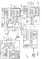
- FIG. 1 this figure shows a block diagram of one possible and non-limiting exemplary system in which the exemplary embodiments may be practiced.
- a user equipment (UE) 110 is in wireless communication with a wireless network 100.
- a UE is a wireless, typically mobile device that can access a wireless network.
- the UE 110 includes one or more processors 120, one or more memories 125, and one or more transceivers 130 interconnected through one or more buses 127.
- Each of the one or more transceivers 130 includes a receiver, Rx, 132 and a transmitter, Tx, 133.
- the one or more buses 127 may be address, data, or control buses, and may include any interconnection mechanism, such as a series of lines on a motherboard or integrated circuit, fiber optics or other optical communication equipment, and the like.
- the one or more transceivers 130 are connected to one or more antennas 128.
- the one or more memories 125 include computer program code 123.
- the UE 110 includes a control module, comprising one of or both parts 140-1 and/or 140-2, which may be implemented in a number of ways.
- the control module 140 may be implemented in hardware as control module 140-1, such as being implemented as part of the one or more processors 120.
- the control module 140-1 may be implemented also as an integrated circuit or through other hardware such as a programmable gate array.
- control module may be implemented as control module 140-2, which is implemented as computer program code 123 and is executed by the one or more processors 120.
- the one or more memories 125 and the computer program code 123 may be configured to, with the one or more processors 120, cause the user equipment 110 to perform one or more of the operations as described herein.
- the UE 110 communicates with eNB 170 via a wireless link 111.
- the eNB (evolved NodeB)/DU 170 is a base station (e.g., for LTE, long term evolution) that provides access by wireless devices such as the UE 110 to the wireless network 100.
- the eNB 170 includes one or more processors 152, one or more memories 155, one or more network interfaces (N/W I/F(s)) 161, and one or more transceivers 160 interconnected through one or more buses 157.
- Each of the one or more transceivers 160 includes a receiver, Rx, 162 and a transmitter, Tx, 163.
- the one or more transceivers 160 are connected to one or more antennas 158.
- the one or more memories 155 include computer program code 153.
- the eNB 170 includes a determination module, comprising one of or both parts 150-1 and/or 150-2, which may be implemented in a number of ways.
- the determination module may be implemented in hardware as determination module 150-1, such as being implemented as part of the one or more processors 152.
- the determination module 150-1 may be implemented also as an integrated circuit or through other hardware such as a programmable gate array.
- the determination module may be implemented as determination module 150-2, which is implemented as computer program code 153 and is executed by the one or more processors 152.
- the one or more memories 155 and the computer program code 153 are configured to, with the one or more processors 152, cause the eNB 170 to perform one or more of the operations as described herein.
- the one or more network interfaces 161 communicate over a network such as via the links 176 and 131.
- Two or more eNBs 170 may communicate using, e.g., link 176.
- the link 176 may be wired or wireless or both and may implement, e.g., an X2 interface.
- the one or more buses 157 may be address, data, or control buses, and may include any interconnection mechanism, such as a series of lines on a motherboard or integrated circuit, fiber optics or other optical communication equipment, wireless channels, and the like.
- the one or more transceivers 160 may be implemented as a remote radio head (RRH) 195, with the other elements of the eNB 170 being physically in a different location from the RRH, and the one or more buses 157 could be implemented in part as fiber optic cable to connect the other elements of the eNB 170 to the RRH 195.
- RRH remote radio head
- each cell can correspond to a single carrier and an eNB may use multiple carriers. So if there are three 120 degree cells per carrier and two carriers, then the eNB has a total of 6 cells.
- FIG. 1 also is also representative of a centralized network deployment scenario.
- the 5G-CU 191 is also included as part of the wireless network 100.
- the 5G-CU 191 includes one or more processors 192, one or more memories 194, and one or more network interfaces (N/W I/F(s)) 198 interconnected through one or more buses 196.
- the one or more memories 194 include computer program code 193.
- the 5G-CU 191 includes a determination module, comprising one of or both parts 199-1 and/or 199-2, which may be implemented in a number of ways.
- the determination module may be implemented in hardware as determination module 199-1, such as being implemented as part of the one or more processors 192.
- the determination module 199-1 may be implemented also as an integrated circuit or through other hardware such as a programmable gate array.
- the determination module may be implemented as determination module 199-2, which is implemented as computer program code 193 and is executed by the one or more processors 192.
- the one or more memories 194 and the computer program code 193 are configured to, with the one or more processors 192, cause the 5G-CU 191 to perform one or more of the operations as described herein.
- the one or more network interfaces 198 communicate over a network such as via the links 197 and 131.
- one or more 5G-CUs 191 may communicate using, e.g., a wired or wireless or both and may implement, e.g., a similar interface such as the X2 interface.
- the eNB/DU 170 may be a distributed unit (DU), and the DU 170 may communicate with a 5G-CU 191 via link 197, such as an Ethernet link, for example, and in turn the 5G-CU 191 may communicate with the NCE 190 via link 131, such as via a fiber optic link.
- DU distributed unit
- link 197 such as an Ethernet link
- NCE 190 may communicate with link 131, such as via a fiber optic link.
- the wireless network 100 may include a network control element (NCE) 190 that may include MME (Mobility Management Entity)/SGW (Serving Gateway) functionality, and which provides connectivity with a further network, such as a telephone network and/or a data communications network (e.g., the Internet).
- NCE network control element
- MME Mobility Management Entity
- SGW Serving Gateway
- At least one of the eNB/DU 170 and the 5G-CU 191 is coupled via a link 131 to the NCE 190.
- the link 131 may be implemented as, e.g., an S1 interface.
- the NCE 190 includes one or more processors 175, one or more memories 171, and one or more network interfaces (N/W I/F(s)) 180, interconnected through one or more buses 185.
- the one or more memories 171 include computer program code 173.
- the one or more memories 171 and the computer program code 173 are configured to, with the one or more processors 175, cause the NCE
- the wireless network 100 may implement network virtualization, which is the process of combining hardware and software network resources and network functionality into a single, software-based administrative entity, a virtual network.
- Network virtualization involves platform virtualization, often combined with resource virtualization.
- Network virtualization is categorized as either external, combining many networks, or parts of networks, into a virtual unit, or internal, providing network-like functionality to software containers on a single system. Note that the virtualized entities that result from the network virtualization are still implemented, at some level, using hardware such as processors 152 or 175 and memories 155 and 171, and also such virtualized entities create technical effects.
- the computer readable memories 125, 155, 194, and 171 may be of any type suitable to the local technical environment and may be implemented using any suitable data storage technology, such as semiconductor based memory devices, flash memory, magnetic memory devices and systems, optical memory devices and systems, fixed memory and removable memory.
- the computer readable memories 125, 155, 194, and 171 may be means for performing storage functions.
- the processors 120, 152, 192, and 175 may be of any type suitable to the local technical environment, and may include one or more of general purpose computers, special purpose computers, microprocessors, digital signal processors (DSPs) and processors based on a multi-core processor architecture, as non-limiting examples.
- the processors 120, 152, 192, and 175 may be means for performing functions, such as controlling the UE 110, eNB 170, and other functions as described herein.
- the various embodiments of the user equipment 110 can include, but are not limited to, cellular telephones such as smart phones, tablets, personal digital assistants (PDAs) having wireless communication capabilities, portable computers having wireless communication capabilities, image capture devices such as digital cameras having wireless communication capabilities, gaming devices having wireless communication capabilities, music storage and playback appliances having wireless communication capabilities, Internet appliances permitting wireless Internet access and browsing, tablets with wireless communication capabilities, as well as portable units or terminals that incorporate combinations of such functions.
- cellular telephones such as smart phones, tablets, personal digital assistants (PDAs) having wireless communication capabilities, portable computers having wireless communication capabilities, image capture devices such as digital cameras having wireless communication capabilities, gaming devices having wireless communication capabilities, music storage and playback appliances having wireless communication capabilities, Internet appliances permitting wireless Internet access and browsing, tablets with wireless communication capabilities, as well as portable units or terminals that incorporate combinations of such functions.
- PDAs personal digital assistants
- portable computers having wireless communication capabilities
- image capture devices such as digital cameras having wireless communication capabilities
- gaming devices having wireless communication capabilities
- music storage and playback appliances having wireless communication capabilities
- Embodiments described herein are applicable to both a distributed architecture (such as shown in FIG. 2 , for example) and a centralized architecture (such as shown in FIG. 3 , for example).
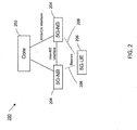
- FIG. 2 this figure shows a simplified non-limiting example of a distributed deployment architecture 200 in accordance with exemplary embodiments.
- the distributed deployment architecture 200 shows a core network 202, two 5G-NBs 204 and a 5G-UE 206.
- the 5G NBs 204 may communicate by the help of Shared Data Layer (SDL) or horizontal interface (such as link 176 in FIG. 1 , for example).
- SDL Shared Data Layer
- the 5G-UE 206 and 5G-NB may be implemented as UE 110 and eNB 170 from FIG. 1 , respectively.
- the core network 202 may include, for example, NCE 190.
- the 5G-UE sends an uplink signal, which in this example is shown as uplink beacon 208, to one or more of the 5G-NBs 204 in accordance with exemplary embodiments described below.
- FIG. 3 shows a simplified example of a centralized deployment architecture 300.
- the centralized deployment architecture 300 shows a core network 302, a 5G centralized unit (CU) 304, two 5G distributed units (DUs) 306, and a 5G-UE 206.
- the 5G-UE 206 transmits an uplink signal, which in this example is shown as uplink beacon 308, to the DUs 306.
- the CU 304 may correspond to 5G-CU 191, for example; and DU 306 may correspond to eNB/DU 170, for example.
- centralized processing may be performed with the upper protocol layer functions being placed in CUs 304 (e.g.
- the protocol stack can be split between CU 304 and DU 306 in low (e.g. PHY) or high (e.g. RLC or PDCP) protocol layer. In this way, two types of centralized architectures may be considered, as described in more detail below.
- a CU e.g. CU 304
- non-real time protocols such as Radio Resource Control (RRC), Packet Data Convergence Protocol (PDCP), and possibly part of Radio Link Control (RLC)
- RRC Radio Resource Control
- PDCP Packet Data Convergence Protocol
- RLC Radio Link Control
- a DU e.g. DU 306
- a DU also possibly hosts one or many remote RF units (e.g. RF transceivers).
- the DU and CU are connected with a non-ideal (e.g. Ethernet) transport, and a DU and RRH are connected with an ideal (e.g. fiber) transport.
- a CU terminates the core network (CN) control-plane and user-plane interfaces, and may also be connected by a horizontal interface to other DUs, similar to the LTE X2 interface for example.
- CN core network
- a CU, underlying DUs, and RRHs form a logical eNB (or, in 5G terms, a gNB).
- This type of centralized architecture is not currently supported by the LTE specification; however, proprietary realizations for LTE exist, such as NOKIA's Cloud D-RAN architecture, for example).
- the CU contains non-real time and realtime protocols, possibly down to the physical layer (LI). The exact split is still being discussed in 3GPP.
- a CU may host multiple RRHs, connected by an ideal transport. Similar to the first type of centralized architecture, a CU terminates CN control-pane and user-plane interface and may be connected to other CUs by a horizontal interface. Together, a CU and RRHs form logical eNB.
- the distributed nodes e.g. RRHs
- have a common MAC layer hence enabling tighter coordination techniques such as CoMP and CA.
- this type of architecture is already supported by LTE specification.
- the first type of architecture relates to multi-connectivity like coordination
- the second type relates to CoMP or carrier aggregation like coordination
- the exemplary embodiments relate to the first type of centralized architecture, as they address, for example, the fast activation of multi-connectivity. It is further noted that the decisions for fast activation of CoMP or CA legs occur at the L1/MAC layers, and therefore present different problems than fast activation of multi-connectivity legs which occur at the RRC layer.
- multi-connectivity is one of the new features of future wireless networks, such as 5G wireless networks.
- These future wireless networks allow increases in capacity, utilizing millimeter wave (mmWave) frequencies, for example.
- Communication links in mmWave networks are highly susceptible to blocking and therefore may have rapid variations in quality.
- Multi-connectivity allows a user equipment to connect to multiple cells such as mmWave and lower frequencies (e.g. frequencies utilized in LTE) in order to create a more robust connection and to enable services requiring ultra-reliable low latency communications (URLLC).
- mmWave millimeter wave
- URLLC ultra-reliable low latency communications
- the multi-connectivity capable moving devices for example the devices with URLLC services
- the RRC state is configured to be in the low activity state, e.g. RRC Connected Inactive state.
- the device needs to re-establish the active connectivity
- the state transition from inactive state to active state while enabling the multi-connectivity is challenging.
- multi-connectivity consists of multiple radio legs which are allocated from, for example, different base stations.
- the resumption of the connectivity needs to assume downlink measurements of candidate cells over multiple radio legs and potentially new target cells need to be prepared with an up-to-date UE context and timing advance.
- the base station acting as the last serving cell for the UE needs to forward the uplink mobility measurement results to neighboring candidate cells in order to enable activation of multi-connectivity in those cells using the most efficient radio resources.
- the UE When UE moves from cell to cell, it needs to perform measurements to request activation of Dual Connectivity using the trigger event A6 for reporting the SCell/SeNB specific measurements (as described in 3GPP TS 36.331).
- the UE measures two parameters on reference signal: RSRP (Reference Signal Received Power) and RSRQ (Reference Signal Received Quality). Measurements are made in downlink from the serving cell and the neighboring cells and are processed in the UE. Processing is done to filter out the effect of fast-fading and Layer 1 (LI) measurement/estimation errors using a Layer 3 (L3) filter.
- the processed measurements After the trigger event, the processed measurements are reported back to the serving base station in a periodic or event based manner in uplink using radio resource control (RRC) signaling.
- RRC radio resource control
- L3 filtering values are a compromise between user velocity and reporting accuracy. Values between 300ms to 3000ms may be used, where the slowly moving users require longer filtering period due to correlated shadow fading. This adds significant delay to the activation of multi-connectivity. Shorter values of L3 filter will trigger unnecessary additions of secondary links increasing probability of secondary link radio link failure, which is also problematic for URLLC.
- a fast resumption of the connectivity can be achieved using, for example, the standardized methodology of Narrow-band IoT for LTE in Rel-13, where the network can suspend the connection and store the UE Context in RAN.
- the resumption procedure can be combined with Secondary eNB change standardized in LTE Dual-Connectivity to achieve resumption procedure multi-connectivity. It is assumed that this way the resumption of multi-connectivity is faster compared to full RRC_IDLE to RRC _CONNECTED state transition including activation of multi-connectivity.
- the approach may work, the problem in this approach is that the resumption of multiconnectivity is not efficient enough for URLLC applications due to significant signaling overhead and associated delay.
- FIG. 4 this figure illustrates a modified procedure to activate multiconnectivity after connection resumption in accordance with 3GPP TS 36.331.
- This figure shows the significant signaling overhead required to re-activate the multi-connectivity in the new target base station 408 when UE 402 has been suspended with multi-connectivity and the S-SeNB 406 has changed.
- the signaling in the modified procedure shown in FIG. 4 can be summarized as follows:
- the following delay components can be identified from the modified LTE procedure shown in FIG. 4 :
- the delay component may take up to 1 second to resume a multi-connectivity session following the procedures of LTE, the main delay component being UE measurements. Consequently, multi-connectivity cannot be utilized to serve occasional bursts of data with high data rate which leads to inefficient utilization of the UE power resources. Furthermore, the network may not be able to suspend RRC connection in a dynamic manner (e.g. in the time scale of hundreds of milliseconds compared to 5-30 s of LTE) as the multi-connectivity cannot keep up with the state transition dynamics. Consequently, the UE will spend more time in the RRC _CONNECTED state, resulting in worse energy efficiency and increased signaling load.
- uplink signals such as an uplink beacon signal, for example
- fast resume can be accomplished in the following manner:
- the UL beacons may be based on a sequence (preamble) design similar to random access preamble of LTE. Such design allows the following information to be extracted at the DU receiver:
- the beacons from different UEs can be received in a DU based on contention-free (CF) or contention-based (CB) design.
- CF contention-free
- CB contention-based
- each UE is assigned a dedicated beacon signature as part of the RRC connection suspend message.
- CB approach a number of UEs are assigned with the same (or random) signature, hence resulting to collisions.
- the collisions can be effectively reduced in a centralized architecture by a mix of CF and CB approach, e.g. avoiding reuse of a same signature in neighboring cells and assigning different time/frequency resources for a signature to be reused within one cell.
- the residual collisions e.g. occasional receptions of the same sequence from two UEs despite of the previously mentioned measures
- the number of signatures per cell is assumed to be considerably lower compared to the number of UEs. This is partly because beacons are transmitted only by the UEs needing multi-connectivity (mainly eMBB slice), and partly because the beacons might be transmitted for a limited period of time after suspending a multi-connectivity session.
- the number of signatures can be further reduced by configuring a UE to transmit beacons only if the measured DL quality of at least N cells satisfies a quality criterion and/or the cell advertises multi-connectivity as part of the system information broadcast.
- the beacon signature space should be designed according to expected demand.
- CUs participating in beacon reception are time synchronized to a level similar to TDD operation and eICIC (e.g. around 1-10 ⁇ s in LTE). Furthermore, the UE is expected to be synchronized to the downlink of each cell detected for neighboring cell measurements. Based on these assumptions, the synchronization of uplink beacons may be performed according to the following:
- a further variation of option 2 is to estimate the TA only per layer (e.g. per macro and small cell layer) exploiting the fact that a single TA might be applicable to a group of cells (e.g. all neighboring small cells). Another possibility is to transmit the beacons for TA estimation with a longer cycle than the beacons for link quality estimation.
- beacon transmission may be one aspect of the configurable CONNECTED _INACTIVE state.
- the following aspects may be configured by the network, allowing flexible utilization of the feature:
- the beacons are beamformed in both UE and network sides. This setup provides maximum coverage (the same as for the U-plane) for the beacon reception, however sacrificing the spectrum efficiency due to beam sweeping in both UE and network ends. It is however quite unlikely that such extensive coverage would be needed as there is not much point for selecting a very weak link for multi-connectivity.
- the beacons are (RX-) beamformed only in network side, hence reducing the sweeping time and complexity, but with a slight impact on coverage.
- Beamforming is not utilized for beacon transmission and reception. This approach significantly reduces the beacon coverage due to absence of high gain from RX beamforming. It may still be a valid approach for cases with high threshold for secondary link.
- the beacon based activation is expected to be directly applicable to scenario where the UE is camped to LTE cell (DU) and requires a fast activation of LTE-5G multiconnectivity. The opposite might not be possible, assuming that the LTE cell (DU) does not support beacon reception.
- the beacon based activation may be exploited in the context of network slicing.
- the UE may be configured to transmit beacons in CONNECTED INACTIVE state according to the slices supported by the network and UE.
- an UE supporting eMBB and URLLC slices may be configured by the network to camp on the macro layer (to save battery and reduce signaling), however transmitting beacons to URLLC and eMBB layers (cells dedicated to those use cases) to allow fast activation of multiconnectivity.
- the exemplary embodiments may be applicable to distributed architectures (where radio nodes are connected by horizontal interface, such as shown in FIG. 2 for example) by the help of Shared Data Layer (SDL) or horizontal interface (X2).
- SDL Shared Data Layer
- X2 horizontal interface
- the distributed nodes (5G-NB) are connected to SDL entity/layer or another 5G-NB, allowing one 5G-NB to expose the UL measurements to other 5G-NBs.
- each 5G-NB can monitor the link quality and timing advances in a similar manner as in the CU/DU architecture described above.
- the embodiments enable fast activation of multi-connectivity in cloud borders, e.g., when the UE moves from a cell covered by one CU to a cell that is covered by another CU.
- the distributed deployment scenario is similar to the LTE system architecture, where each 5G-NB hosts the full protocol and inter-5G-NB signaling is needed to exchange mobility related information between nodes.
- 3GPP RAN2 meeting #94 it has been agreed to study the upper layer aggregation (e.g. DC-like) for standalone 5G deployments. Therefore, 5G should also support centralization of the upper layers of the radio protocol stack.
- the UE is aware of the radio resources from multiple DUs connecting to same/different CUs and the incoming beacon from UE to multiple DUs is available in the CU(s).
- FIG. 5 is a logic flow diagram for fast activation of multi-connectivity utilizing uplink signals. This figure further illustrates the operation of an exemplary method, a result of execution of computer program instructions embodied on a computer readable memory, functions performed by logic implemented in hardware, and/or interconnected means for performing functions in accordance with exemplary embodiments.
- the control module 140-1 and/or 140-2 may include multiples ones of the blocks in FIG. 5 , where each included block is an interconnected means for performing the function in the block.
- the blocks in FIG. 5 are assumed to be performed by the UE 110, e.g., under control of the control module 140-1 and/or 140-2 at least in part.
- the method comprises: transmitting, by a user equipment, at least one uplink signal to a plurality of network nodes of a wireless network based at least on the user equipment being in a first radio resource control state such that the user equipment maintains connectivity with one of the network nodes as indicated by block 502; receiving at least one connection message comprising a command to connect to at least two of the network nodes for communication, wherein the command is based at least on measurements extracted from the at least one uplink signal as indicated by block 504; in response to the at least one connection message, changing from the first radio resource control state to a second radio resource control state as indicated by block 506; and transmitting data utilizing multiple communication links via the at least two network nodes as indicated by block 508.
- the first radio resource control state may be at least one of: an inactive state and a low activity state, and wherein the user equipment may maintain connectivity based on cell-reselection parameters configured by the wireless network and downlink measurements.
- the first radio resource control state is a RRC_CONNECTED_INACTIVE state; and the second radio resource control state is a RRC_CONNECTED state.
- the method further includes initiating a random access procedure at least by transmitting a request message towards the network node that the user equipment maintains connectivity with. Initiating the random access procedure may be performed in response to the user equipment determining a need to transmit uplink data to the wireless network, and wherein an initial uplink message of the random access procedure may comprise the request message.
- the user equipment may be downlink synchronized with each of the plurality of network nodes while the user equipment is in the first radio resource control state.
- the at least one uplink signal may include a cell-specific timing shift.
- the at least one connection message may include cell-specific uplink timing advance values for each of the at least two network nodes.
- Receiving the at least one connection message includes receiving a first connection message from a first network node comprising a command to connect to the first network node, and receiving a second connection message from a second network node comprising a command to connect to the second network node.
- Each of the one or more network nodes may be connected to a centralized network node, and wherein radio resource control protocol (RRC) and packet data convergence protocol (PDCP) may be located at the centralized network node comprises, and at least the medium access layer (MAC) protocol and physical layer (PHY) protocol may be located at the plurality of network nodes.
- RRC radio resource control protocol
- PDCP packet data convergence protocol
- the at least one uplink signal may comprise an uplink beacon signal.
- an apparatus may comprise: at least one processor; and at least one non-transitory memory including computer program code, the at least one memory and the computer program code configured to, with the at least one processor, cause the apparatus at least to perform: transmit, by a user equipment, at least one uplink signal to a plurality of network nodes of a wireless network based at least on the user equipment being in a first radio resource control state such that the user equipment maintains connectivity with one of the network nodes; receive at least one connection message comprising a command to connect to at least two of the network nodes for communication, wherein the command is based at least on measurements extracted from the at least one uplink signal; in response to the at least one connection message, change from the first radio resource control state to a second radio resource control state; and transmit data utilizing multiple communication links via the at least two network nodes.
- the first radio resource control state is at least one of: an inactive state and a low activity state, and wherein the user equipment maintains connectivity based on cell-reselection parameters configured by the wireless network and downlink measurements.
- the first radio resource control state is a RRC _CONNECTED INACTIVE state; and the second radio resource control state is a RRC _CONNECTED state.
- the at least one memory and the computer program code may be configured to, with the at least one processor, cause the apparatus at least to perform: initiate a random access procedure at least by transmitting a request message towards the network node that the user equipment maintains connectivity with.
- Initiation of the random access procedure may be performed in response to determination of a need to transmit uplink data to the wireless network, and wherein an initial uplink message of the random access procedure may comprise the request message.
- the user equipment may be downlink synchronized with each of the plurality of network nodes while the user equipment is in the first radio resource control state.
- the at least one uplink signal may comprise a cell-specific timing shift.
- the at least one connection message may comprise cell-specific uplink timing advance values for each of the at least two network nodes.
- Receiving the at least one connection message may include receiving a first connection message from a first network node comprising a command to connect to the first network node, and receiving a second connection message from a second network node comprising a command to connect to the second network node.
- Each of the plurality of network nodes may be connected to a centralized network node, and wherein radio resource control protocol (RRC) and packet data convergence protocol (PDCP) may be located at the centralized network node comprises, and at least the medium access layer (MAC) protocol and physical layer (PHY) protocol may be located at the plurality of network nodes.
- RRC radio resource control protocol
- PDCP packet data convergence protocol
- the at least one uplink signal comprises an uplink beacon signal.
- An example embodiment may be provided in a non-transitory program storage device, such as memory 125 shown in Fig. 1 for example, readable by a machine, tangibly embodying a program of instructions executable by the machine for performing operations.
- the operations may include: transmitting, by a user equipment, at least one uplink signal to a plurality of network nodes of a wireless network based at least on the user equipment being in a first radio resource control state such that the user equipment maintains connectivity with one of the network nodes; receiving at least one connection message comprising a command to connect to at least two of the network nodes for communication, wherein the command is based at least on measurements extracted from the at least one uplink signal; in response to the at least one connection message, changing from the first radio resource control state to a second radio resource control state; and transmitting data utilizing multiple communication links via the at least two network nodes.
- an apparatus may comprise: means for transmitting, by a user equipment, at least one uplink signal to a plurality of network nodes of a wireless network based at least on the user equipment being in a first radio resource control state such that the user equipment maintains connectivity with one of the network nodes; means for receiving at least one connection message comprising a command to connect to at least two of the network nodes for communication, wherein the command is based at least on measurements extracted from the at least one uplink signal; in response to the at least one connection message, means for changing from the first radio resource control state to a second radio resource control state; and means for transmitting data utilizing multiple communication links via the at least two network nodes.
- FIG. 6 is a logic flow diagram for fast activation of multi-connectivity utilizing uplink signals. This figure further illustrates the operation of an exemplary method, a result of execution of computer program instructions embodied on a computer readable memory, functions performed by logic implemented in hardware, and/or interconnected means for performing functions in accordance with exemplary embodiments.
- the determination module 199-1 and/or 199-2 may include multiples ones of the blocks in FIG. 6 , where each included block is an interconnected means for performing the function in the block.
- the blocks in FIG. 6 are assumed to be performed by a centralized unit (e.g.5G-CU 191), e.g., under control of the determination module 199-1 and/or 199-2 at least in part.
- a centralized unit e.g.5G-CU 191
- an example method may comprise: receiving, by a first network node connected to a plurality of further network nodes of a wireless network, measurement information for each of a plurality of user equipments, wherein the measurement information is based on uplink signals transmitted from each of the plurality of user equipments in a first radio resource control state as indicated by block 602; maintaining, for each of the plurality of user equipments, a set of candidate links and cell-specific uplink timing advance values based on the measurement information as indicated by block 604; in response to initiation of a random access procedure by a given one of the user equipments, selecting at least two of the further network nodes to be used in a multi-connectivity session for communicating with the given user equipment as indicated by block 606; and causing at least one connection message to be transmitted to the given user equipment comprising a command to connect to the at least two selected network nodes as indicated by block 608.
- the measurement information may include at least one of: a link quality measurement and an estimate for uplink advance timing.
- the connection message may include cell-specific uplink timing advance values for each of the selected at least two network nodes.
- Each of the uplink signals may comprises a cell-specific timing shift.
- the first radio resource control state may be at least one of an inactive state and a low activity state such that a user equipment maintains connectivity with one of the plurality of further network nodes based on cell-reselection parameters configured by the wireless network and downlink measurements.
- the radio resource control protocol (RRC) and packet data convergence protocol (PDCP) may be located at the first network node comprises, and at least the medium access layer (MAC) protocol and physical layer (PHY) protocol may be located at the plurality of further network nodes.
- the at least one connection message may include causing a first connection message to be transmitted from a first network node comprising a command to connect to the first network node, and causing a second connection message to be transmitted from a second network node comprising a command to connect to the second network node.
- an apparatus may comprise: at least one processor; and at least one non-transitory memory including computer program code, the at least one memory and the computer program code configured to, with the at least one processor, cause the apparatus at least to perform: receive, by a first network node connected to a plurality of further network nodes of a wireless network, measurement information for each of a plurality of user equipments, wherein the measurement information is based on uplink signals transmitted from each of the plurality of user equipments in a first radio resource control state; maintain, for each of the plurality of user equipments, a set of candidate links and cell-specific uplink timing advance values based on the measurement information; in response to initiation of a random access procedure by a given one of the user equipments, select at least two of the further network nodes to be used in a multi-connectivity session for communicating with the given user equipment; and cause at least one connection message to be transmitted to the given user equipment comprising a command to connect to the at least two selected network nodes.
- An example embodiment may be provided in a non-transitory program storage device, such as memory 194 shown in Fig. 1 for example, readable by a machine, tangibly embodying a program of instructions executable by the machine for performing operations.
- the operations may include: receiving, by a first network node connected to a plurality of further network nodes of a wireless network, measurement information for each of a plurality of user equipments, wherein the measurement information is based on uplink signals transmitted from each of the plurality of user equipments in a first radio resource control state; maintaining, for each of the plurality of user equipments, a set of candidate links and cell-specific uplink timing advance values based on the measurement information; in response to initiation of a random access procedure by a given one of the user equipments, selecting at least two of the further network nodes to be used in a multi-connectivity session for communicating with the given user equipment; and causing at least one connection message to be transmitted to the given user equipment comprising a command to connect to the at least two selected network no
- an apparatus may comprise: means for receiving, by a first network node connected to a plurality of further network nodes of a wireless network, measurement information for each of a plurality of user equipments, wherein the measurement information is based on uplink signals transmitted from each of the plurality of user equipments in a first radio resource control state; maintaining, for each of the plurality of user equipments, a set of candidate links and cell-specific uplink timing advance values based on the measurement information; in response to initiation of a random access procedure by a given one of the user equipments, means for selecting at least two of the further network nodes to be used in a multi-connectivity session for communicating with the given user equipment; and means for causing at least one connection message to be transmitted to the given user equipment comprising a command to connect to the at least two selected network nodes.
- FIG. 7 is a logic flow diagram for fast activation of multi-connectivity utilizing uplink signals. This figure further illustrates the operation of an exemplary method, a result of execution of computer program instructions embodied on a computer readable memory, functions performed by logic implemented in hardware, and/or interconnected means for performing functions in accordance with exemplary embodiments.
- the determination module 150-1 and/or 150-2 may include multiples ones of the blocks in FIG. 7 , where each included block is an interconnected means for performing the function in the block.
- the blocks in FIG. 7 are assumed to be performed by a distributed unit (e.g. eNB/DU 170), e.g., under control of the determination module 150-1 and/or 150-2 at least in part.
- a distributed unit e.g. eNB/DU 170
- an example method may comprise: receiving, by a first network node connected to a second network node of a wireless network, an uplink signal from a user equipment, wherein the user equipment is in a first radio resource control state as indicated by block 702; extracting information based on the at least one uplink signal, the information comprising at least one of: a link quality measurement and an estimate for uplink advance timing as indicated by block 704; and transmitting the extracted information to the second network node as indicated by block 706.
- the first network node may be a distributed node, and the second network node may be a centralized node.
- Radio resource control protocol (RRC) and packet data convergence protocol (PDCP) may be located at the centralized network node, and at least the medium access layer (MAC) protocol and physical layer (PHY) protocol may be located at the second network node.
- the method may further comprise transmitting a connection message from the first network node to the user equipment, the connection message including a command to connect to at least the first network node as part of a multi-connectivity session.
- the method may further comprise receiving data from the user equipment in response to the connection message, wherein the user equipment is in a second radio resource control state. The received data may be received via a communication link comprising at least the first network node.
- Transmission of the connection message may be based at least on the uplink signal from the user equipment.
- the connection message may include cell-specific uplink timing advance value for the first network node.
- the first radio resource control state may be at least one of: an inactive state and a low activity state.
- the user equipment may be downlink synchronized with the first network node while the user equipment is in the first radio resource control state.
- the received at least one uplink signal may include a cell-specific timing shift.
- an apparatus may comprise: at least one processor; and at least one non-transitory memory including computer program code, the at least one memory and the computer program code configured to, with the at least one processor, cause the apparatus at least to perform: receive, by a first network node connected to a second network node of a wireless network, an uplink signal from a user equipment, wherein the user equipment is in a first radio resource control state; extract information based on the at least one uplink signal, the information comprising at least one of: a link quality measurement and an estimate for uplink advance timing; and transmit the extracted information to the second network node.
- An example embodiment may be provided in a non-transitory program storage device, such as memory 155 shown in Fig. 1 for example, readable by a machine, tangibly embodying a program of instructions executable by the machine for performing operations.
- the operations may include: receiving, by a first network node connected to a second network node of a wireless network, an uplink signal from a user equipment, wherein the user equipment is in a first radio resource control state; extracting information based on the at least one uplink signal, the information comprising at least one of: a link quality measurement and an estimate for uplink advance timing; and transmitting the extracted information to the second network node.
- an apparatus may comprise: means for receiving, by a first network node connected to a second network node of a wireless network, an uplink signal from a user equipment, wherein the user equipment is in a first radio resource control state; means for extracting information based on the at least one uplink signal, the information comprising at least one of: a link quality measurement and an estimate for uplink advance timing; and means for transmitting the extracted information to the second network node.
- a technical effect of one or more of the example embodiments disclosed herein is significantly faster activation of multi-connectivity for an INACTIVE state UE compared to LTE.
- the network knows the best links at the time of initiating the connection resume, and therefore no time is spent on waiting for the UE measuring, averaging the measurement results and sending measurement report(s) for secondary link(s);
- the UE context is readily available at the central processing node, therefore there is no need for SeNB Addition Request signaling between nodes providing radio resources for multi-connectivity; in distributed deployments, the potential target 5G-NBs with secondary links can be prepared for fast activation of multiconnectivity;
- the UE location is known at a cell or TRP level, therefore the UE does not need to be paged for a mobile-terminated call;
- the timing advance values to the cells providing multi-connectivity are known in advance by the network, therefore random access is only needed in the case of mobile originated call
- Another technical effect of one or more of the example embodiments disclosed herein is lower UE power consumption in CONNECTED ACTIVE state. This is due to the increased utilization of multi-connectivity to convey small bursts of data, implying higher utilization of frequency domain resources, and ultimately higher UE power efficiency.
- 3GPP document R2-165555 titled Energy conserved operation evaluation, Source: Huawei, HiSilicon , it was demonstrated that power consumption impact might not be significant due to relatively small contribution of beacon transmission for the overall power ramp-up/rampdown process. However, it is noted that that beacon transmission may have some negative impact on the UE power efficiency of CONNECTED _INACTIVE state compared to IDLE state.
- Another technical effect of one or more of the example embodiments disclosed herein is lower signaling overhead to activate multi-connectivity.
- embodiments described herein allow most of the delays associated with the measurements and measurement reporting procedures to be avoided.
- Management of secondary links requires less signaling since the CU maintains a set of candidate links per UE, representing the preferred choices for a multi-connectivity session.
- Random access procedure towards secondary links to gain uplink synchronization can be avoided when CU maintains cell-specific uplink timing advance values per UE.
- the secondary links can be activated immediately with a single RRCConnectionResume message, which includes a command to resume multiconnectivity to indicated cells. This message comprises cell-specific timing advance value(s) to be applied for subsequent UL transmissions.
- Embodiments herein may be implemented in software (executed by one or more processors), hardware (e.g., an application specific integrated circuit), or a combination of software and hardware.
- the software e.g., application logic, an instruction set
- a "computer-readable medium” may be any media or means that can contain, store, communicate, propagate or transport the instructions for use by or in connection with an instruction execution system, apparatus, or device, such as a computer, with one example of a computer described and depicted, e.g., in FIG. 1 .
- a computer-readable medium may comprise a computer-readable storage medium (e.g., memories 125, 155, 171, 194 or other device) that may be any media or means that can contain, store, and/or transport the instructions for use by or in connection with an instruction execution system, apparatus, or device, such as a computer.
- a computer-readable storage medium does not comprise propagating signals.
- the different functions discussed herein may be performed in a different order and/or concurrently with each other. Furthermore, if desired, one or more of the above-described functions may be optional or may be combined.
Landscapes
- Engineering & Computer Science (AREA)
- Computer Networks & Wireless Communication (AREA)
- Signal Processing (AREA)
- Mobile Radio Communication Systems (AREA)
Claims (13)
- Verfahren, das Folgendes umfasst:Übertragen (502) von mindestens einem Uplinksignal durch eine Teilnehmereinrichtung zu einer Vielzahl von Netzwerkknoten eines drahtlosen Netzwerks mindestens teilweise darauf basierend, dass sich die Teilnehmereinrichtung in einem Zustand RRC_CONNECTED_INACTIVE befindet, derart, dass die Teilnehmereinrichtung eine Konnektivität mit einem der Netzwerkknoten aufrechterhält;gekennzeichnet durch:in Reaktion auf das Initiieren einer Direktzugriffsprozedur mit dem Netzwerkknoten, mit dem die Teilnehmereinrichtung eine Konnektivität aufrechterhält, Empfangen (504) von mindestens einer Verbindungsnachricht, die einen Befehl zum Verbinden mit mindestens zwei der Netzwerkknoten zur Kommunikation umfasst;in Reaktion auf die mindestens eine Verbindungsnachricht Wechseln (506) vom Zustand RRC_CONNECTED_INACTIVE zu einem Zustand RRC_CONNECTED; undÜbertragen (508) von Daten in einer Multikonnektivitätssitzung unter Verwendung von mehreren Kommunikationslinks via die mindestens zwei Netzwerkknoten.
- Verfahren nach Anspruch 1, wobei die Teilnehmereinrichtung eine Konnektivität auf Basis von Zellneuauswahlparametern, die vom drahtlosen Netzwerk ausgelegt sind, und Downlinkmessungen im Zustand RRC_CONNECTED_INACTIVE aufrechterhält.
- Verfahren nach Anspruch 1, wobei die Initiierung der Direktzugriffsprozedur in Reaktion auf die Bestimmung einer Notwendigkeit, Uplinkdaten zum drahtlosen Netzwerk zu übertragen, durchgeführt wird und wobei eine anfängliche Uplinknachricht der Direktzugriffsprozedur die Anforderungsnachricht umfasst.
- Verfahren nach einem der Ansprüche 1-3, wobei die Teilnehmereinrichtung mit jedem der Vielzahl von Netzwerkknoten downlinksynchronisiert ist, während sich die Teilnehmereinrichtung im Zustand RRC_CONNECTED_INACTIVE befindet.
- Verfahren nach einem der Ansprüche 1-4, wobei das mindestens eine Uplinksignal eine zellspezifische Zeitverschiebung umfasst.
- Verfahren nach einem der Ansprüche 1-5, wobei die mindestens eine Verbindungsnachricht zellspezifische Uplinkzeitvorlaufswerte für jeden der mindestens zwei Netzwerkknoten umfasst.
- Verfahren nach einem der Ansprüche 1-7, wobei jeder der Vielzahl von Netzwerkknoten mit einem zentralisierten Netzwerkknoten verbunden ist und wobei sich ein Funkressourcensteuerprotokoll und ein Paketdatenkonvergenzprotokoll am zentralisierten Netzwerkknoten befinden und sich mindestens ein Medienzugriffsschichtprotokoll und ein physisches Schichtprotokoll an der Vielzahl von Netzwerkknoten befinden.
- Verfahren nach einem der Ansprüche 1-7, wobei das mindestens eine Uplinksignal ein Uplinkbeaconsignal umfasst.
- Verfahren, das Folgendes umfasst:Empfangen (auf 602) von Messinformationen für jede einer Vielzahl von Teilnehmereinrichtungen durch einen ersten Netzwerkknoten, der mit einer Vielzahl von weiteren Netzwerkknoten eines drahtlosen Netzwerks verbunden ist, wobei die Messinformationen auf Uplinksignalen basieren, die von jeder der Vielzahl von Teilnehmereinrichtungen in einem Zustand RRC_CONNECTED_INACTIVE empfangen werden;gekennzeichnet durch:Aufrechterhalten (604) eines Satzes von Linkkandidaten und zellspezifischen Uplinkzeitvorlaufswerten für jede der Vielzahl von Teilnehmereinrichtungen auf Basis der Messinformationen;in Reaktion auf die Initiierung einer Direktzugriffsprozedur durch eine gegebene der Teilnehmereinrichtungen Auswählen (606) von mindestens zwei der weiteren Netzwerkknoten, die in einer Multikonnektivitätssitzung zum Kommunizieren mit der gegebenen Teilnehmereinrichtung zu verwenden sind; undBewirken (608), dass mindestens eine Verbindungsnachricht, die einen Befehl zum Verbinden mit den mindestens zwei ausgewählten Netzwerkknoten umfasst, zur gegebenen Teilnehmereinrichtung übertragen wird.
- Verfahren nach Anspruch 9, wobei die Messinformationen mindestens eines von Folgendem umfassen:
eine Linkqualitätsmessung und eine Schätzung für eine Uplinkvorlaufzeit. - Verfahren nach einem der Ansprüche 9-10, wobei die Verbindungsnachricht zellspezifische Uplinkzeitvorlaufswerte für jeden der ausgewählten mindestens zwei Netzwerkknoten umfasst.
- Vorrichtung, die Mittel zum Durchführen des Verfahrens nach einem der Ansprüche 1 bis 8 oder des Verfahrens nach einem der Ansprüche 9 bis 11 umfasst.
- Nichttransitorisches computerlesbares Medium, das einen Computerprogrammcode umfasst, der darauf gespeichert ist und, wenn er von einer Vorrichtung ausgeführt wird, bewirkt, dass die Vorrichtung das Verfahren nach einem der Ansprüche 1 bis 8 oder das Verfahren nach einem der Ansprüche 9 bis 11 durchführt.
Applications Claiming Priority (1)
| Application Number | Priority Date | Filing Date | Title |
|---|---|---|---|
| US15/293,795 US10925107B2 (en) | 2016-10-14 | 2016-10-14 | Fast activation of multi-connectivity utilizing uplink signals |
Publications (2)
| Publication Number | Publication Date |
|---|---|
| EP3310120A1 EP3310120A1 (de) | 2018-04-18 |
| EP3310120B1 true EP3310120B1 (de) | 2021-09-15 |
Family
ID=60001690
Family Applications (1)
| Application Number | Title | Priority Date | Filing Date |
|---|---|---|---|
| EP17193414.4A Active EP3310120B1 (de) | 2016-10-14 | 2017-09-27 | Schnelle aktivierung von mehrfachkonnektivität unter verwendung von uplink-signalen |
Country Status (3)
| Country | Link |
|---|---|
| US (1) | US10925107B2 (de) |
| EP (1) | EP3310120B1 (de) |
| CN (1) | CN107959983B (de) |
Families Citing this family (39)
| Publication number | Priority date | Publication date | Assignee | Title |
|---|---|---|---|---|
| WO2018112871A1 (zh) * | 2016-12-23 | 2018-06-28 | 富士通株式会社 | 数据发送/接收装置、方法以及通信系统 |
| US10660065B2 (en) | 2017-04-13 | 2020-05-19 | Lg Electronics Inc. | Method for transmitting a paging message and device supporting the same |
| JP7019721B2 (ja) * | 2017-04-20 | 2022-02-15 | オッポ広東移動通信有限公司 | 通信方法、アクセスネットワークデバイス及び端末デバイス |
| CN110999513B (zh) * | 2017-06-06 | 2023-08-11 | 瑞典爱立信有限公司 | 建立中性主机网络与一个或多个虚拟无线电接入网络之间的连接的方法 |
| WO2018228451A1 (en) * | 2017-06-15 | 2018-12-20 | Qualcomm Incorporated | Techniques and apparatuses for user equipment mobility in multi-connectivity mode |
| EP3530068A2 (de) | 2017-06-16 | 2019-08-28 | Ofinno, LLC | Konfigurationsupdate für verteilte einheit |
| CN109150451B (zh) * | 2017-06-16 | 2023-06-20 | 华为技术有限公司 | 通信方法、网络节点和无线接入网系统 |
| US10952273B2 (en) * | 2017-08-10 | 2021-03-16 | At&T Intellectual Property I, L.P. | Detecting and correcting radio link failures based on different usage scenarios |
| US11191060B2 (en) * | 2018-03-15 | 2021-11-30 | Sprint Communications Company L.P. | Dynamic wireless network architecture to serve uplink-centric and downlink-centric user applications |
| WO2019190383A1 (en) * | 2018-03-26 | 2019-10-03 | Telefonaktiebolaget Lm Ericsson (Publ) | Suspending/resuming measurements in rrc inactive state |
| US11178719B2 (en) * | 2018-05-07 | 2021-11-16 | Htc Corporation | Device and method of handling an radio resource control resume procedure |
| EP3761732B1 (de) | 2018-05-07 | 2022-09-28 | Guangdong Oppo Mobile Telecommunications Corp., Ltd. | Verfahren und vorrichtung zum aussetzen einer rrc-verbindung und computerspeichermedium |
| CN110475389B (zh) | 2018-05-09 | 2022-10-14 | 中兴通讯股份有限公司 | 一种空口非激活态维持方法和装置 |
| AU2019267190B2 (en) * | 2018-05-10 | 2022-06-09 | Telefonaktiebolaget Lm Ericsson (Publ) | Protocols and architectures for NR-NR dual connectivity (NR-DC) |
| WO2019223861A1 (en) * | 2018-05-23 | 2019-11-28 | Nokia Technologies Oy | Increasing number of connected user equipments on radio access network apparatus |
| WO2019233740A1 (en) * | 2018-06-08 | 2019-12-12 | Telefonaktiebolaget Lm Ericsson (Publ) | Application of integrity protection in a wireless communication network |
| CN110636565B (zh) * | 2018-06-21 | 2021-01-22 | 电信科学技术研究院有限公司 | Rrc非活跃状态下的数据传输方法、装置、终端及设备 |
| US11071047B2 (en) * | 2018-06-22 | 2021-07-20 | Huawei Technologies Co., Ltd. | Systems and methods for reduced network signalling based on mapping |
| EP3588851B1 (de) * | 2018-06-28 | 2023-02-01 | Mitsubishi Electric R&D Centre Europe B.V. | Verfahren zur konfiguration eines zugangsnetzknotens und vorrichtung zur implementierung desselben |
| CN110662285B (zh) * | 2018-06-29 | 2022-11-08 | 中兴通讯股份有限公司 | 定时调整信息的配置方法及装置 |
| CN110769439B (zh) | 2018-07-27 | 2022-02-25 | 维沃移动通信有限公司 | 测量方法、终端和网络侧设备 |
| CN110881205B (zh) * | 2018-09-05 | 2021-03-16 | 维沃移动通信有限公司 | 一种终端驻留方法、信息传输方法、终端及网络设备 |
| EP3744150A1 (de) * | 2018-10-26 | 2020-12-02 | Google LLC | Effiziente handhabung einer ressourcensteuerungszustandsänderung und mehrknotenkonnektivität |
| GB2580296A (en) * | 2018-11-09 | 2020-07-22 | Stratospheric Platforms Ltd | Communication network and method of making a connection |
| CN109673023B (zh) * | 2018-11-12 | 2022-04-01 | 中国科学院上海高等研究院 | 链路通信模式的操作方法、系统、计算机存储介质、设备 |
| CN113287345A (zh) * | 2019-01-11 | 2021-08-20 | 诺基亚通信公司 | 侧链路同步更新 |
| JP7369778B2 (ja) * | 2019-01-28 | 2023-10-26 | オッポ広東移動通信有限公司 | 無線通信方法、端末機器、並びにネットワーク機器 |
| WO2020167203A1 (en) * | 2019-02-14 | 2020-08-20 | Telefonaktiebolaget Lm Ericsson (Publ) | Methods and apparatuses for managing scell state during ue suspend/resume |
| CN113678550A (zh) * | 2019-03-29 | 2021-11-19 | 诺基亚技术有限公司 | 降级信令 |
| CN111615141B (zh) * | 2019-04-09 | 2022-04-22 | 维沃移动通信有限公司 | 测量方法、测量配置方法、终端和网络设备 |
| CN112040554A (zh) * | 2019-06-03 | 2020-12-04 | 华硕电脑股份有限公司 | 移动终止提前数据传送和预配置上行链路资源方法和设备 |
| US20220279620A1 (en) * | 2019-07-19 | 2022-09-01 | Telefonaktiebolaget Lm Ericsson (Publ) | Methods, Apparatus, and Machine-Readable Media Relating to Dual- or Multi-Connectivity in a Wireless Communication Network |
| EP4014602A1 (de) * | 2019-08-16 | 2022-06-22 | Telefonaktiebolaget Lm Ericsson (Publ) | Iab-cu verwaltete zeitmuster-konfiguration für iab-interknoten-messung |
| CN114365513A (zh) * | 2019-09-19 | 2022-04-15 | 瑞典爱立信有限公司 | 用于协调的信令的方法和通信装置 |
| EP3827640B1 (de) * | 2019-10-14 | 2023-04-05 | Google LLC | Schnelle mcg-fehlerbehebung mit sekundärknotenwechsel |
| KR20210077547A (ko) * | 2019-12-17 | 2021-06-25 | 삼성전자주식회사 | 무선 통신 시스템에서 성능 측정을 위한 장치 및 방법 |
| US11924895B2 (en) * | 2020-02-14 | 2024-03-05 | Qualcomm Incorporated | Techniques for new radio layer two relay |
| CN113518417A (zh) * | 2020-04-09 | 2021-10-19 | 华为技术有限公司 | 一种通信方法和装置 |
| WO2022042927A1 (en) * | 2020-08-26 | 2022-03-03 | Nokia Technologies Oy | Efficient support for user equipment with redundant protocol data unit session |
Family Cites Families (12)
| Publication number | Priority date | Publication date | Assignee | Title |
|---|---|---|---|---|
| CA2666955C (en) * | 2006-10-25 | 2014-12-09 | Samsung Electronics Co., Ltd. | Method and apparatus for allocating radio resource using random access procedure in a mobile communication system |
| US8320286B2 (en) | 2007-03-09 | 2012-11-27 | Broadcom Corporation | Infrastructure offload wake on wireless LAN (WOWL) |
| KR101634177B1 (ko) * | 2009-01-15 | 2016-06-28 | 엘지전자 주식회사 | 데이터 패킷의 처리 및 전송 방법 |
| CN101938344A (zh) * | 2009-06-29 | 2011-01-05 | 宏达国际电子股份有限公司 | 处理传输以及传输状态信息的方法及其相关通讯装置 |
| US9526091B2 (en) * | 2012-03-16 | 2016-12-20 | Intel Corporation | Method and apparatus for coordination of self-optimization functions in a wireless network |
| EP2908570B1 (de) * | 2012-11-13 | 2019-06-19 | Huawei Technologies Co., Ltd. | Verfahren und basisstation zur übertragung von daten |
| US9832659B2 (en) | 2012-12-03 | 2017-11-28 | Lg Electronics Inc. | Method and apparatus for supporting control plane and user plane in wireless communication system |
| WO2014130708A1 (en) | 2013-02-21 | 2014-08-28 | Altiostar Networks, Inc. | Systems and methods for scheduling of data packets based on application detection in a base station |
| CN104469945B (zh) | 2013-09-12 | 2019-01-25 | 索尼公司 | Nct scc的激活控制装置和方法、管理方法、以及基站装置 |
| US10129857B2 (en) * | 2014-11-06 | 2018-11-13 | Qualcomm Incorporated | Band occupancy techniques for transmissions in unlicensed spectrum |
| US10630410B2 (en) * | 2016-05-13 | 2020-04-21 | Telefonaktiebolaget Lm Ericsson (Publ) | Network architecture, methods, and devices for a wireless communications network |
| US10349328B2 (en) * | 2016-07-22 | 2019-07-09 | Google Llc | Mobility in a multi-network wireless system |
-
2016
- 2016-10-14 US US15/293,795 patent/US10925107B2/en active Active
-
2017
- 2017-09-27 EP EP17193414.4A patent/EP3310120B1/de active Active
- 2017-10-13 CN CN201710954446.1A patent/CN107959983B/zh not_active Expired - Fee Related
Also Published As
| Publication number | Publication date |
|---|---|
| EP3310120A1 (de) | 2018-04-18 |
| US20180110082A1 (en) | 2018-04-19 |
| US10925107B2 (en) | 2021-02-16 |
| CN107959983A (zh) | 2018-04-24 |
| CN107959983B (zh) | 2022-01-25 |
Similar Documents
| Publication | Publication Date | Title |
|---|---|---|
| EP3310120B1 (de) | Schnelle aktivierung von mehrfachkonnektivität unter verwendung von uplink-signalen | |
| EP3840479B1 (de) | Signalisierungsmitteilungssynchronisierung | |
| US20180249461A1 (en) | Methods and apparatuses to form self-organized multi-hop millimeter wave backhaul links | |
| EP2876967B1 (de) | Drx-operation mit dualer konnektivität | |
| EP3081048B1 (de) | Netzknoten, benutzervorrichtung und verfahren zur ermöglichung einer d2d-kommunikation | |
| US10057937B2 (en) | Communications via multiple access points | |
| US11937113B2 (en) | Flexible early measurement reporting | |
| CN115023981B (zh) | 用于rrc非活动状态的寻呼的wus | |
| EP2962489B1 (de) | Lieferung von messungen | |
| WO2021170110A1 (zh) | 一种通信方法及装置 | |
| WO2018233709A1 (zh) | 一种通信方法及设备 | |
| WO2022068797A1 (zh) | 网络接入方法、网络接入装置、终端和网络侧设备 | |
| JP2023532529A (ja) | 無線品質が低い端末の存在の判定、および端末が使用する基準信号の調整 | |
| US20220279395A1 (en) | Early data transmission for dual connectivity or carrier aggregation | |
| US20220232440A1 (en) | Configuration of carriers for non-mobility related purposes | |
| US20150245301A1 (en) | User equipment, a network node and methods for device discovery in a device-to-device (d2d) communication in a wireless telecommunications network | |
| CN117099388A (zh) | Rrm测量活动报告和使用 | |
| EP3198901B1 (de) | Vorrichtungsentdeckung in einer vorrichtung-zu-vorrichtung-kommunikation unter verwendung von zwei arten der entdeckung | |
| CN114747289A (zh) | 基于单时机周期值来适配最大允许的cca失败 | |
| CN113543192B (zh) | 一种测量配置方法及装置 | |
| WO2024060210A1 (en) | Configuration for gap for musim capable ue | |
| WO2019028838A1 (en) | NETWORK TRENCH-SPECIFIC PAGING CYCLES FOR WIRELESS NETWORKS | |
| KR20230147726A (ko) | 정보 전송, 획득 방법 및 네트워크 측 장치 | |
| EP4356642A1 (de) | Beschleunigte messberichterstattung (xmr) | |
| JP2022108426A (ja) | ユーザ機器、基地局及びネットワークノード |
Legal Events
| Date | Code | Title | Description |
|---|---|---|---|
| PUAI | Public reference made under article 153(3) epc to a published international application that has entered the european phase |
Free format text: ORIGINAL CODE: 0009012 |
|
| STAA | Information on the status of an ep patent application or granted ep patent |
Free format text: STATUS: THE APPLICATION HAS BEEN PUBLISHED |
|
| AK | Designated contracting states |
Kind code of ref document: A1 Designated state(s): AL AT BE BG CH CY CZ DE DK EE ES FI FR GB GR HR HU IE IS IT LI LT LU LV MC MK MT NL NO PL PT RO RS SE SI SK SM TR |
|
| AX | Request for extension of the european patent |
Extension state: BA ME |
|
| STAA | Information on the status of an ep patent application or granted ep patent |
Free format text: STATUS: REQUEST FOR EXAMINATION WAS MADE |
|
| 17P | Request for examination filed |
Effective date: 20181016 |
|
| RBV | Designated contracting states (corrected) |
Designated state(s): AL AT BE BG CH CY CZ DE DK EE ES FI FR GB GR HR HU IE IS IT LI LT LU LV MC MK MT NL NO PL PT RO RS SE SI SK SM TR |
|
| STAA | Information on the status of an ep patent application or granted ep patent |
Free format text: STATUS: REQUEST FOR EXAMINATION WAS MADE |
|
| RAP1 | Party data changed (applicant data changed or rights of an application transferred) |
Owner name: NOKIA TECHNOLOGIES OY |
|
| RIC1 | Information provided on ipc code assigned before grant |
Ipc: H04W 36/38 20090101ALN20210217BHEP Ipc: H04W 76/15 20180101AFI20210217BHEP Ipc: H04W 36/00 20090101ALN20210217BHEP Ipc: H04W 76/27 20180101ALI20210217BHEP Ipc: H04B 7/06 20060101ALN20210217BHEP |
|
| GRAP | Despatch of communication of intention to grant a patent |
Free format text: ORIGINAL CODE: EPIDOSNIGR1 |
|
| STAA | Information on the status of an ep patent application or granted ep patent |
Free format text: STATUS: GRANT OF PATENT IS INTENDED |
|
| GRAJ | Information related to disapproval of communication of intention to grant by the applicant or resumption of examination proceedings by the epo deleted |
Free format text: ORIGINAL CODE: EPIDOSDIGR1 |
|
| STAA | Information on the status of an ep patent application or granted ep patent |
Free format text: STATUS: REQUEST FOR EXAMINATION WAS MADE |
|
| RIC1 | Information provided on ipc code assigned before grant |
Ipc: H04B 7/06 20060101ALN20210316BHEP Ipc: H04W 36/00 20090101ALN20210316BHEP Ipc: H04W 36/38 20090101ALN20210316BHEP Ipc: H04W 76/27 20180101ALI20210316BHEP Ipc: H04W 76/15 20180101AFI20210316BHEP |
|
| INTG | Intention to grant announced |
Effective date: 20210329 |
|
| GRAP | Despatch of communication of intention to grant a patent |
Free format text: ORIGINAL CODE: EPIDOSNIGR1 |
|
| STAA | Information on the status of an ep patent application or granted ep patent |
Free format text: STATUS: GRANT OF PATENT IS INTENDED |
|
| INTC | Intention to grant announced (deleted) | ||
| RIC1 | Information provided on ipc code assigned before grant |
Ipc: H04B 7/06 20060101ALN20210421BHEP Ipc: H04W 36/00 20090101ALN20210421BHEP Ipc: H04W 36/38 20090101ALN20210421BHEP Ipc: H04W 76/27 20180101ALI20210421BHEP Ipc: H04W 76/15 20180101AFI20210421BHEP |
|
| INTG | Intention to grant announced |
Effective date: 20210507 |
|
| GRAS | Grant fee paid |
Free format text: ORIGINAL CODE: EPIDOSNIGR3 |
|
| GRAA | (expected) grant |
Free format text: ORIGINAL CODE: 0009210 |
|
| STAA | Information on the status of an ep patent application or granted ep patent |
Free format text: STATUS: THE PATENT HAS BEEN GRANTED |
|
| AK | Designated contracting states |
Kind code of ref document: B1 Designated state(s): AL AT BE BG CH CY CZ DE DK EE ES FI FR GB GR HR HU IE IS IT LI LT LU LV MC MK MT NL NO PL PT RO RS SE SI SK SM TR |
|
| REG | Reference to a national code |
Ref country code: CH Ref legal event code: EP |
|
| REG | Reference to a national code |
Ref country code: DE Ref legal event code: R096 Ref document number: 602017045972 Country of ref document: DE |
|
| REG | Reference to a national code |
Ref country code: IE Ref legal event code: FG4D |
|
| REG | Reference to a national code |
Ref country code: AT Ref legal event code: REF Ref document number: 1431547 Country of ref document: AT Kind code of ref document: T Effective date: 20211015 |
|
| PGFP | Annual fee paid to national office [announced via postgrant information from national office to epo] |
Ref country code: DE Payment date: 20210914 Year of fee payment: 5 |
|
| REG | Reference to a national code |
Ref country code: LT Ref legal event code: MG9D |
|
| REG | Reference to a national code |
Ref country code: NL Ref legal event code: MP Effective date: 20210915 |
|
| PG25 | Lapsed in a contracting state [announced via postgrant information from national office to epo] |
Ref country code: RS Free format text: LAPSE BECAUSE OF FAILURE TO SUBMIT A TRANSLATION OF THE DESCRIPTION OR TO PAY THE FEE WITHIN THE PRESCRIBED TIME-LIMIT Effective date: 20210915 Ref country code: SE Free format text: LAPSE BECAUSE OF FAILURE TO SUBMIT A TRANSLATION OF THE DESCRIPTION OR TO PAY THE FEE WITHIN THE PRESCRIBED TIME-LIMIT Effective date: 20210915 Ref country code: HR Free format text: LAPSE BECAUSE OF FAILURE TO SUBMIT A TRANSLATION OF THE DESCRIPTION OR TO PAY THE FEE WITHIN THE PRESCRIBED TIME-LIMIT Effective date: 20210915 Ref country code: LT Free format text: LAPSE BECAUSE OF FAILURE TO SUBMIT A TRANSLATION OF THE DESCRIPTION OR TO PAY THE FEE WITHIN THE PRESCRIBED TIME-LIMIT Effective date: 20210915 Ref country code: BG Free format text: LAPSE BECAUSE OF FAILURE TO SUBMIT A TRANSLATION OF THE DESCRIPTION OR TO PAY THE FEE WITHIN THE PRESCRIBED TIME-LIMIT Effective date: 20211215 Ref country code: NO Free format text: LAPSE BECAUSE OF FAILURE TO SUBMIT A TRANSLATION OF THE DESCRIPTION OR TO PAY THE FEE WITHIN THE PRESCRIBED TIME-LIMIT Effective date: 20211215 Ref country code: FI Free format text: LAPSE BECAUSE OF FAILURE TO SUBMIT A TRANSLATION OF THE DESCRIPTION OR TO PAY THE FEE WITHIN THE PRESCRIBED TIME-LIMIT Effective date: 20210915 |
|
| REG | Reference to a national code |
Ref country code: AT Ref legal event code: MK05 Ref document number: 1431547 Country of ref document: AT Kind code of ref document: T Effective date: 20210915 |
|
| PG25 | Lapsed in a contracting state [announced via postgrant information from national office to epo] |
Ref country code: LV Free format text: LAPSE BECAUSE OF FAILURE TO SUBMIT A TRANSLATION OF THE DESCRIPTION OR TO PAY THE FEE WITHIN THE PRESCRIBED TIME-LIMIT Effective date: 20210915 Ref country code: GR Free format text: LAPSE BECAUSE OF FAILURE TO SUBMIT A TRANSLATION OF THE DESCRIPTION OR TO PAY THE FEE WITHIN THE PRESCRIBED TIME-LIMIT Effective date: 20211216 |
|
| PG25 | Lapsed in a contracting state [announced via postgrant information from national office to epo] |
Ref country code: AT Free format text: LAPSE BECAUSE OF FAILURE TO SUBMIT A TRANSLATION OF THE DESCRIPTION OR TO PAY THE FEE WITHIN THE PRESCRIBED TIME-LIMIT Effective date: 20210915 |
|
| REG | Reference to a national code |
Ref country code: CH Ref legal event code: PL |
|
| REG | Reference to a national code |
Ref country code: BE Ref legal event code: MM Effective date: 20210930 |
|
| PG25 | Lapsed in a contracting state [announced via postgrant information from national office to epo] |
Ref country code: IS Free format text: LAPSE BECAUSE OF FAILURE TO SUBMIT A TRANSLATION OF THE DESCRIPTION OR TO PAY THE FEE WITHIN THE PRESCRIBED TIME-LIMIT Effective date: 20220115 Ref country code: SM Free format text: LAPSE BECAUSE OF FAILURE TO SUBMIT A TRANSLATION OF THE DESCRIPTION OR TO PAY THE FEE WITHIN THE PRESCRIBED TIME-LIMIT Effective date: 20210915 Ref country code: SK Free format text: LAPSE BECAUSE OF FAILURE TO SUBMIT A TRANSLATION OF THE DESCRIPTION OR TO PAY THE FEE WITHIN THE PRESCRIBED TIME-LIMIT Effective date: 20210915 Ref country code: RO Free format text: LAPSE BECAUSE OF FAILURE TO SUBMIT A TRANSLATION OF THE DESCRIPTION OR TO PAY THE FEE WITHIN THE PRESCRIBED TIME-LIMIT Effective date: 20210915 Ref country code: PT Free format text: LAPSE BECAUSE OF FAILURE TO SUBMIT A TRANSLATION OF THE DESCRIPTION OR TO PAY THE FEE WITHIN THE PRESCRIBED TIME-LIMIT Effective date: 20220117 Ref country code: PL Free format text: LAPSE BECAUSE OF FAILURE TO SUBMIT A TRANSLATION OF THE DESCRIPTION OR TO PAY THE FEE WITHIN THE PRESCRIBED TIME-LIMIT Effective date: 20210915 Ref country code: NL Free format text: LAPSE BECAUSE OF FAILURE TO SUBMIT A TRANSLATION OF THE DESCRIPTION OR TO PAY THE FEE WITHIN THE PRESCRIBED TIME-LIMIT Effective date: 20210915 Ref country code: ES Free format text: LAPSE BECAUSE OF FAILURE TO SUBMIT A TRANSLATION OF THE DESCRIPTION OR TO PAY THE FEE WITHIN THE PRESCRIBED TIME-LIMIT Effective date: 20210915 Ref country code: EE Free format text: LAPSE BECAUSE OF FAILURE TO SUBMIT A TRANSLATION OF THE DESCRIPTION OR TO PAY THE FEE WITHIN THE PRESCRIBED TIME-LIMIT Effective date: 20210915 Ref country code: CZ Free format text: LAPSE BECAUSE OF FAILURE TO SUBMIT A TRANSLATION OF THE DESCRIPTION OR TO PAY THE FEE WITHIN THE PRESCRIBED TIME-LIMIT Effective date: 20210915 Ref country code: AL Free format text: LAPSE BECAUSE OF FAILURE TO SUBMIT A TRANSLATION OF THE DESCRIPTION OR TO PAY THE FEE WITHIN THE PRESCRIBED TIME-LIMIT Effective date: 20210915 |
|
| REG | Reference to a national code |
Ref country code: DE Ref legal event code: R097 Ref document number: 602017045972 Country of ref document: DE |
|
| PG25 | Lapsed in a contracting state [announced via postgrant information from national office to epo] |
Ref country code: MC Free format text: LAPSE BECAUSE OF FAILURE TO SUBMIT A TRANSLATION OF THE DESCRIPTION OR TO PAY THE FEE WITHIN THE PRESCRIBED TIME-LIMIT Effective date: 20210915 |
|
| PLBE | No opposition filed within time limit |
Free format text: ORIGINAL CODE: 0009261 |
|
| STAA | Information on the status of an ep patent application or granted ep patent |
Free format text: STATUS: NO OPPOSITION FILED WITHIN TIME LIMIT |
|
| PG25 | Lapsed in a contracting state [announced via postgrant information from national office to epo] |
Ref country code: LU Free format text: LAPSE BECAUSE OF NON-PAYMENT OF DUE FEES Effective date: 20210927 Ref country code: IE Free format text: LAPSE BECAUSE OF NON-PAYMENT OF DUE FEES Effective date: 20210927 Ref country code: DK Free format text: LAPSE BECAUSE OF FAILURE TO SUBMIT A TRANSLATION OF THE DESCRIPTION OR TO PAY THE FEE WITHIN THE PRESCRIBED TIME-LIMIT Effective date: 20210915 Ref country code: BE Free format text: LAPSE BECAUSE OF NON-PAYMENT OF DUE FEES Effective date: 20210930 |
|
| 26N | No opposition filed |
Effective date: 20220616 |
|
| GBPC | Gb: european patent ceased through non-payment of renewal fee |
Effective date: 20211215 |
|
| PG25 | Lapsed in a contracting state [announced via postgrant information from national office to epo] |
Ref country code: SI Free format text: LAPSE BECAUSE OF FAILURE TO SUBMIT A TRANSLATION OF THE DESCRIPTION OR TO PAY THE FEE WITHIN THE PRESCRIBED TIME-LIMIT Effective date: 20210915 Ref country code: LI Free format text: LAPSE BECAUSE OF NON-PAYMENT OF DUE FEES Effective date: 20210930 Ref country code: CH Free format text: LAPSE BECAUSE OF NON-PAYMENT OF DUE FEES Effective date: 20210930 |
|
| PG25 | Lapsed in a contracting state [announced via postgrant information from national office to epo] |
Ref country code: GB Free format text: LAPSE BECAUSE OF NON-PAYMENT OF DUE FEES Effective date: 20211215 |
|
| PG25 | Lapsed in a contracting state [announced via postgrant information from national office to epo] |
Ref country code: FR Free format text: LAPSE BECAUSE OF NON-PAYMENT OF DUE FEES Effective date: 20211115 |
|
| PG25 | Lapsed in a contracting state [announced via postgrant information from national office to epo] |
Ref country code: IT Free format text: LAPSE BECAUSE OF FAILURE TO SUBMIT A TRANSLATION OF THE DESCRIPTION OR TO PAY THE FEE WITHIN THE PRESCRIBED TIME-LIMIT Effective date: 20210915 |
|
| REG | Reference to a national code |
Ref country code: DE Ref legal event code: R119 Ref document number: 602017045972 Country of ref document: DE |
|
| PG25 | Lapsed in a contracting state [announced via postgrant information from national office to epo] |
Ref country code: HU Free format text: LAPSE BECAUSE OF FAILURE TO SUBMIT A TRANSLATION OF THE DESCRIPTION OR TO PAY THE FEE WITHIN THE PRESCRIBED TIME-LIMIT; INVALID AB INITIO Effective date: 20170927 |
|
| PG25 | Lapsed in a contracting state [announced via postgrant information from national office to epo] |
Ref country code: CY Free format text: LAPSE BECAUSE OF FAILURE TO SUBMIT A TRANSLATION OF THE DESCRIPTION OR TO PAY THE FEE WITHIN THE PRESCRIBED TIME-LIMIT Effective date: 20210915 |
|
| PG25 | Lapsed in a contracting state [announced via postgrant information from national office to epo] |
Ref country code: DE Free format text: LAPSE BECAUSE OF NON-PAYMENT OF DUE FEES Effective date: 20230401 |
|
| PG25 | Lapsed in a contracting state [announced via postgrant information from national office to epo] |
Ref country code: MK Free format text: LAPSE BECAUSE OF FAILURE TO SUBMIT A TRANSLATION OF THE DESCRIPTION OR TO PAY THE FEE WITHIN THE PRESCRIBED TIME-LIMIT Effective date: 20210915 |