EP3310113B1 - Random access methods - Google Patents
Random access methods Download PDFInfo
- Publication number
- EP3310113B1 EP3310113B1 EP16806554.8A EP16806554A EP3310113B1 EP 3310113 B1 EP3310113 B1 EP 3310113B1 EP 16806554 A EP16806554 A EP 16806554A EP 3310113 B1 EP3310113 B1 EP 3310113B1
- Authority
- EP
- European Patent Office
- Prior art keywords
- user equipment
- random access
- cell
- resource
- contention
- Prior art date
- Legal status (The legal status is an assumption and is not a legal conclusion. Google has not performed a legal analysis and makes no representation as to the accuracy of the status listed.)
- Active
Links
- 238000000034 method Methods 0.000 title claims description 83
- 230000005540 biological transmission Effects 0.000 claims description 91
- 230000015654 memory Effects 0.000 description 20
- 238000010586 diagram Methods 0.000 description 12
- 238000007726 management method Methods 0.000 description 8
- 230000002093 peripheral effect Effects 0.000 description 8
- 238000004891 communication Methods 0.000 description 7
- 238000005259 measurement Methods 0.000 description 7
- 230000006870 function Effects 0.000 description 6
- 230000008569 process Effects 0.000 description 5
- 230000004044 response Effects 0.000 description 4
- 238000004088 simulation Methods 0.000 description 4
- 230000003993 interaction Effects 0.000 description 3
- 238000012986 modification Methods 0.000 description 3
- 230000004048 modification Effects 0.000 description 3
- 230000011664 signaling Effects 0.000 description 3
- 230000001360 synchronised effect Effects 0.000 description 3
- 230000001419 dependent effect Effects 0.000 description 2
- 238000013459 approach Methods 0.000 description 1
- 230000008901 benefit Effects 0.000 description 1
- 230000001413 cellular effect Effects 0.000 description 1
- 230000007774 longterm Effects 0.000 description 1
- 238000013439 planning Methods 0.000 description 1
- 238000013468 resource allocation Methods 0.000 description 1
- 238000000926 separation method Methods 0.000 description 1
Images


Classifications
-
- H—ELECTRICITY
- H04—ELECTRIC COMMUNICATION TECHNIQUE
- H04W—WIRELESS COMMUNICATION NETWORKS
- H04W74/00—Wireless channel access, e.g. scheduled or random access
- H04W74/08—Non-scheduled or contention based access, e.g. random access, ALOHA, CSMA [Carrier Sense Multiple Access]
- H04W74/0833—Non-scheduled or contention based access, e.g. random access, ALOHA, CSMA [Carrier Sense Multiple Access] using a random access procedure
-
- H—ELECTRICITY
- H04—ELECTRIC COMMUNICATION TECHNIQUE
- H04W—WIRELESS COMMUNICATION NETWORKS
- H04W48/00—Access restriction; Network selection; Access point selection
- H04W48/08—Access restriction or access information delivery, e.g. discovery data delivery
- H04W48/10—Access restriction or access information delivery, e.g. discovery data delivery using broadcasted information
-
- H—ELECTRICITY
- H04—ELECTRIC COMMUNICATION TECHNIQUE
- H04W—WIRELESS COMMUNICATION NETWORKS
- H04W56/00—Synchronisation arrangements
- H04W56/001—Synchronization between nodes
-
- H—ELECTRICITY
- H04—ELECTRIC COMMUNICATION TECHNIQUE
- H04W—WIRELESS COMMUNICATION NETWORKS
- H04W72/00—Local resource management
- H04W72/20—Control channels or signalling for resource management
- H04W72/23—Control channels or signalling for resource management in the downlink direction of a wireless link, i.e. towards a terminal
-
- H—ELECTRICITY
- H04—ELECTRIC COMMUNICATION TECHNIQUE
- H04W—WIRELESS COMMUNICATION NETWORKS
- H04W72/00—Local resource management
- H04W72/50—Allocation or scheduling criteria for wireless resources
- H04W72/535—Allocation or scheduling criteria for wireless resources based on resource usage policies
-
- H—ELECTRICITY
- H04—ELECTRIC COMMUNICATION TECHNIQUE
- H04W—WIRELESS COMMUNICATION NETWORKS
- H04W74/00—Wireless channel access, e.g. scheduled or random access
- H04W74/08—Non-scheduled or contention based access, e.g. random access, ALOHA, CSMA [Carrier Sense Multiple Access]
- H04W74/0866—Non-scheduled or contention based access, e.g. random access, ALOHA, CSMA [Carrier Sense Multiple Access] using a dedicated channel for access
-
- H—ELECTRICITY
- H04—ELECTRIC COMMUNICATION TECHNIQUE
- H04W—WIRELESS COMMUNICATION NETWORKS
- H04W76/00—Connection management
- H04W76/10—Connection setup
- H04W76/11—Allocation or use of connection identifiers
-
- H—ELECTRICITY
- H04—ELECTRIC COMMUNICATION TECHNIQUE
- H04W—WIRELESS COMMUNICATION NETWORKS
- H04W76/00—Connection management
- H04W76/20—Manipulation of established connections
- H04W76/27—Transitions between radio resource control [RRC] states
-
- H—ELECTRICITY
- H04—ELECTRIC COMMUNICATION TECHNIQUE
- H04W—WIRELESS COMMUNICATION NETWORKS
- H04W80/00—Wireless network protocols or protocol adaptations to wireless operation
- H04W80/02—Data link layer protocols
-
- H—ELECTRICITY
- H04—ELECTRIC COMMUNICATION TECHNIQUE
- H04W—WIRELESS COMMUNICATION NETWORKS
- H04W56/00—Synchronisation arrangements
- H04W56/0005—Synchronisation arrangements synchronizing of arrival of multiple uplinks
Definitions
- the present invention relates to the field of random access, and particularly to a method and device for a random access.
- LTE Long Term Evolution
- a procedure of a non-contention based random access generally includes three steps.
- a procedure of a contention based random access generally includes four steps.
- a small cell may be provided with a deployed hotspot in a high frequency band (e.g., 5.9GHz) in a future communication system (e.g., a 5G system).
- a high frequency band e.g., 5.9GHz
- a future communication system e.g., a 5G system
- the cell may operate as a standalone cell to allow a UE to access and reside separately.
- the cell In a second mode which is a non-standalone mode, the cell operates only as a resource, and does not allow a UE to access and reside separately.
- An example of a method according to the invention for use in an access node comprises: receiving signals comprising multiple instances of an uplink Random Access message; spatially resolving the received signals to identify directions from which the uplink Random Access message was received; and transmitting distinct downlink Random Access messages in the identified directions from which the uplink Random Access message was received.
- Document US2012/0008524A1 discloses a user equipment for obtaining data for observing performance related to Random Access in a cellular radio system is provided.
- the user equipment can connect to the system.
- the user equipment measures and stores data needed to compute measurements to be reported to the system.
- the user equipment further generates a measurement report, and transmits the measurement report based on a trigger event.
- Document US2015/0105084A1 discloses a method at a user equipment for handover from a serving cell to a target cell, the method sending a measurement report to the serving cell; and transmitting a reconfiguration complete message to the target cell; wherein the measurement report includes downlink timing measurements for the target cell.
- a method at a source network element for handover of a user equipment from the source network element to a target network element the method receiving a measurement report from the user equipment; sending a handover request to the target network element; receiving a handover request acknowledgement from the target network element, the handover request acknowledgement including a reconfiguration message and at least one downlink subframe in which an uplink grant is expected at the target network element for the user equipment; and forwarding the reconfiguration message and at least one downlink subframe to the user equipment.
- Non contention based HO compares the non-contention based HO procedure with transmission of UE specific signatures on RACH.
- non-contention based HO procedure especially implemented with PDCCH allocation method can provide predictable, shorter U-plane delay and easier NW planning than using normal RACH for TA acquisition in case of HO.
- Document US2014/0334389A1 discloses a wireless access network node receives, from a user equipment (UE), information relating to a random access procedure.
- the wireless access network node sends, to the UE, an indication to stop the random access procedure, based on the received information.
- UE user equipment
- RACH Message Structure (R2-060821; R2-060377) discloses some use cases for RACH and possible content of the RACH message. About 30 bits need to be carried. The length of the message could be constant, as shown in Table 1, but the physical layer may not require this. lt is proposed that RACH is used to inform the network of the establishment cause. lt is also proposes that RACH message should also carry an uplink shared channel capacity request to help the scheduler in LTE_ACTIVE.
- Embodiments of the invention provide a method and device for a random access so as to address the problem in the prior art that there is such a long delay in a random access procedure that hinders it from being applied to a scenario having a strict requirement of delay.
- the invention is set out in the appended set of claims.
- a user equipment transmits identification information of the user equipment to a cell over a resource in a dedicated contention resource pool for a random access; and if the user equipment receives a contention resolution message from the cell, then it will determine whether the random access succeeds according to the contention resolution message.
- a user equipment determines an uplink transmission dedicated resource allocated by a target cell for the user equipment, according to second resource information; and accesses the target cell over the uplink transmission dedicated resource. The number of interaction stages in the random access procedure can be reduced to thereby shorten a delay of the random access, so that it can be applied to a scenario having a strict requirement of delay.
- the embodiments of the invention provide two random access solutions, i.e., a contention based random access solution and a non-contention based random access solution.
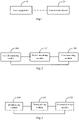
- a first system for a random access includes a user equipment 10, and a network-side device 20 managing cells.
- the user equipment 10 is configured determine a dedicated contention resource pool for a random access when accessing a cell; transmit identification information of the user equipment to the cell over a resource in the dedicated contention resource pool for a random access; and receive a contention resolution message from the cell, and determine whether the random access succeeds, according to the contention resolution message.
- the network-side device 20 is configured to broadcast first resource information for determining the dedicated contention resource pool for a random access; receive the identification information of the user equipment transmitted by the user equipment to access the cell managed by the network-side device, over the dedicated contention resource pool for a random access corresponding to the information about the dedicated contention resource pool for a random access; and transmit the contention resolution message to the user equipment.
- the network-side device If the network-side device receives the identification information of the user equipment, then it will determine that the corresponding user equipment succeeds in contention, and transmit the contention resolution message to the corresponding user equipment.
- the user equipment receives the contention resolution message, then it will determine that the random access succeeds.
- the network-side device broadcasts the first resource information corresponding to at least one dedicated contention resource pool for a random access in the managed cell, and the UE to access the cell firstly reads the broadcasted message and obtains the first resource information, and then transmits the identification information of the UE over the resource in the dedicated contention resource pool for a random access corresponding to the first resource information. If the network-side device receives the identification information of the UE successfully, then it will determine that the UE succeeds in contention, and transmit the contention resolution message to the UE.
- the first resource information for determining the dedicated contention resource pool for a random access is broadcasted by the cell by broadcasting the first resource information in an SIB.
- SIB is a new SIB different from that in the existing 3GPP TS 36.331, or a System Information Block (SIB) obtained by extending the SIB in the 3rd Generation partnership Project (3GPP) Technical Specification (TS) 36.331.
- 3GPP 3rd Generation partnership Project
- TS Technical Specification
- the first resource information includes but will not be limited to a part or all of the following information: a time-frequency position corresponding to the dedicated contention resource pool for a random access, an allowable Modulation and Coding Scheme (MCS) level, and a priority.
- MCS Modulation and Coding Scheme
- the user equipment may determine the dedicated contention resource pool for a random access according to the time-frequency resources upon reception of the first resource information which is broadcasted.
- the user equipment may determine the corresponding dedicated contention resource pools for a random access according to the respective time-frequency positions.
- the user equipment may determine a modulation and coding scheme for transmitting the identification information of the user equipment, according to the MCS level.
- the user equipment may select a dedicated contention resource pool for a random access with the highest priority according to the priorities corresponding to the respective dedicated contention resource pools for a random access.
- the user equipment may transmit the identification information of the user equipment to the cell over the resource in the dedicated contention resource pool for a random access based upon downlink timing of the cell. Stated otherwise, the identification information of the user equipment is transmitted to the cell over the resource in the dedicated contention resource pool for a random access at a downlink receive instance of time of the cell.
- the identification information of the user equipment in the embodiment of the invention may be the following information.
- the identification information of the user equipment will be a Common Control Channel (CCCH) Service Data Unit (SDU); or the identification information of the user equipment may be other information capable of identifying the user equipment.
- CCCH Common Control Channel
- SDU Service Data Unit
- the identification information of the user equipment will be a Cell Radio Network Temporary Identifier (C-RNTI) Media Access Control (MAC) Control Element (CE); or the identification information of the user equipment may be other information capable of identifying the user equipment.
- C-RNTI Cell Radio Network Temporary Identifier
- MAC Media Access Control
- CE Control Element
- the user equipment determines whether the random access succeeds, according to the contention resolution message as follows.
- a CCCH SDU in the contention resolution message is a CCCH SDU transmitted to the cell, then the user equipment will determine that the random access succeeds; otherwise, it will determine that the random access fails.
- the contention resolution message includes a Physical Downlink Control Channel (PDCCH) addressed based upon a C-RNTI MAC CE transmitted to the cell, then the user equipment will determine that the random access succeeds; otherwise, it will determine that the random access fails.
- PDCCH Physical Downlink Control Channel
- the user equipment may reselect a dedicated contention resource pool for a random access, and initiate a random access again, after waiting for a period of time randomly.
- the number of attempts at a random access may be set, and before the number of attempts is reached, the random access will be retried until it succeeds; and if the number of attempts is reached, then the random access will be stopped.
- BSR Buffer Status Report
- the first threshold here may be determined empirically, as a result of simulation, as demanded, etc.
- the network-side device may further allocate a C-RNTI for the user equipment upon determining that the user equipment succeeds in contention.
- the network-side device may allocate the C-RNTI for the user equipment via the contention resolution message; or may allocate the C-RNTI for the user equipment via another message.
- the network-side device may further configure an uplink TA available in the cell for the user equipment upon determining that the user equipment succeeds in contention.
- the second threshold here may be determined empirically, as a result of simulation, as demanded, etc.
- the second threshold may be set to the size of a Timing Advance (TA) adjustment step.
- TA Timing Advance
- the size of a TA adjustment step is 78m.
- the network-side device may allocate the TA for the user equipment via the contention resolution message; or may allocate the TA for the user equipment via another message.
- the network-side device may put the received identification information of the user equipment in the contention resolution message.
- the network-side device may put the C-RNTI and/or the TA allocated for the user equipment in the contention resolution message.
- the network-side device will transmit the contention resolution message to the user equipment over a Physical Downlink Shared Channel (PDSCH) resource scheduled by a PDCCH addressed using a C-RNTI.
- PDSCH Physical Downlink Shared Channel
- the network-side device may further put the TA allocated for the user equipment in the contention resolution message.
- the network-side device transmits the contention resolution message to the user equipment as follows.
- the cell will transmit the contention resolution message to the user equipment over a resource pool corresponding to second resource information broadcasted by the cell, or transmit the contention resolution message to the user equipment over a resource scheduled using a Contention Based Radio Network Temporary Identity (CB-RNTI).
- CB-RNTI Contention Based Radio Network Temporary Identity
- the user equipment receives the contention resolution message over the resource pool corresponding to the second resource information broadcasted by the cell; or receives the contention resolution message over the resource scheduled using the CB-RNTI.
- the cell broadcasts the second resource information by broadcasting the second resource information in an SIB.
- the SIB is a new SIB different from that in the existing 3GPP TS 36.331, or an SIB obtained by extending the SIB in the 3GPP TS 36.331.
- the cell will transmit the contention resolution message to the user equipment over a PDSCH resource scheduled by a PDCCH addressed using a C-RNTI.
- the user equipment receives the contention resolution message over the PDSCH resource scheduled by the PDCCH addressed using the C-RNTI.
- the network-side device may configure a contention resolution time window for the user equipment via broadcast or dedicated signaling (the dedicated signaling is applicable to the case in which user equipment has established an RRC connection).
- the user equipment receives the contention resolution message in the contention resolution time window, then it will determine that it succeeds in contention.
- the user equipment If the user equipment does not receive the contention resolution message in the contention resolution time window, then it will reselect a dedicated contention resource pool for a random access, and initiate a random access again, after waiting for a period of time randomly.
- a first user equipment includes: a first determining module 200 configured to determine a dedicated contention resource pool for a random access when accessing a cell; a first transmitting module 201 configured to transmit identification information of the user equipment to the cell over a resource in the dedicated contention resource pool for a random access; and a first accessing module 202 configured to receive a contention resolution message from the cell, and determine whether the random access succeeds, according to the contention resolution message.
- the first determining module 200 is configured to: determine the dedicated contention resource pool for a random access according to first resource information broadcasted by the cell.
- the first determining module 200 is configured to: determine a plurality of dedicated contention resource pools for a random access according to the first resource information broadcasted by the cell, and select one of the dedicated contention resource pools for a random access.
- the first transmitting module 201 is configured to: transmit the identification information of the user equipment to the cell over the resource in the dedicated contention resource pool for a random access based upon downlink timing of the cell.
- the identification information of the user equipment will be a CCCH SDU; and If the random access is intended for uplink synchronization, then the identification information of the user equipment will be a C-RNTI MAC CE.
- the first accessing module 202 is configured: if a CCCH SDU in the contention resolution message is a CCCH SDU transmitted to the cell, to determine that the random access succeeds; otherwise, to determine that the random access fails; and If the contention resolution message includes a PDCCH addressed using a C-RNTI MAC CE transmitted to the cell, to determine that the random access succeeds; otherwise, to determine that the random access fails.
- the first transmitting module 201 is configured: upon determining the dedicated contention resource pool for a random access when accessing the cell, if the capacity of the determined dedicated contention resource pool for a random access is greater than a first threshold, to transmit BSR information, and/or a part or all of data to be transmitted, to the cell.
- the first accessing module 202 is configured: if the random access of the user equipment is intended for an initial access or to reestablish an RRC connection, to receive the contention resolution message over a resource pool corresponding to second resource information broadcasted by the cell, or to receive the contention resolution message over a resource scheduled using a CB-RNTI; and if the random access of the user equipment is for uplink synchronization, to receive the contention resolution message over a PDSCH resource scheduled by a PDCCH addressed using a C-RNTI.
- the first accessing module 202 is further configured: if the user equipment does not receive the contention resolution message in a contention resolution time window, to trigger the first determining module to reselect a dedicated contention resource pool for a random access, and to initiate a random access again, after waiting for a period of time randomly.
- a first network-side device includes: a broadcasting module 300 configured to broadcast first resource information for determining a dedicated contention resource pool for a random access; a first receiving module 301 configured to receive identification information of a user equipment, transmitted by the user equipment to access a cell managed by the network-side device, over the dedicated contention resource pool for a random access corresponding to the information about the dedicated contention resource pool for a random access; and a first transmitting module 302 configured to transmit a contention resolution message to the user equipment upon reception of the identification information of the user equipment.
- the broadcasting module 300 is configured to broadcast the first resource information in an SIB; here the SIB is a new SIB different from that in the existing 3GPP TS 36.331, or an SIB obtained by extending the SIB in the 3GPP TS 36.331.
- the first receiving module 301 is further configured: upon reception of the identification information of the user equipment, if the user equipment makes an initial access or establishes an RRC connection, to allocate a C-RNTI for the user equipment.
- the first receiving module 301 is further configured: upon reception of the identification information of the user equipment, if the radius of the cell is greater than a second threshold, to configure uplink TA available in the cell for the user equipment.
- the contention resolution message will include the identification information of the user equipment; and if the random access of the user equipment is intended for uplink synchronization, then the contention resolution message will be PDCCH scheduling information, including an initial transmission uplink grant, for a C-RNTI of the user equipment.
- the first transmitting module 302 is configured: if the random access of the user equipment is intended for an initial access or to reestablish an RRC connection, to transmit the contention resolution message to the user equipment over a resource pool corresponding to second resource information broadcasted by the cell, or to transmit the contention resolution message to the user equipment over a resource scheduled using a CB-RNTI; and if the random access of the user equipment is intended for uplink synchronization, to transmit the contention resolution message to the user equipment over a PDSCH resource scheduled by a PDCCH addressed using a C-RNTI.
- the broadcasting module 300 is configured to broadcast the second resource information in an SIB; here the SIB is a new SIB different from that in the existing 3GPP TS 36.331, or an SIB obtained by extending the SIB in the 3GPP TS 36.331.
- a second user equipment includes: a processor 401 configured to read programs in a memory 404 to: determine a dedicated contention resource pool for a random access when accessing a cell; transmit identification information of the user equipment to the cell over a resource in the dedicated contention resource pool for a random access through a transceiver 402; and receive a contention resolution message from the cell through the transceiver 402, and determine whether the random access succeeds, according to the contention resolution message; and the transceiver 402 configured to be controlled by the processor 401 to receive and transmit data.
- the processor 401 is configured to: determine the dedicated contention resource pool for a random access according to first resource information broadcasted by the cell.
- the processor 401 is configured to: determine a plurality of dedicated contention resource pools for a random access according to the first resource information broadcasted by the cell, and select one of the dedicated contention resource pools for a random access.
- the processor 401 is configured to: transmit the identification information of the user equipment to the cell over the resource in the dedicated contention resource pool for a random access based upon downlink timing of the cell.
- the identification information of the user equipment will be a CCCH SDU; and if the random access is intended for uplink synchronization, then the identification information of the user equipment will be a C-RNTI MAC CE.
- the processor 401 is configured: if a CCCH SDU in the contention resolution message is a CCCH SDU transmitted to the cell, to determine that the random access succeeds; otherwise, to determine that the random access fails; and if the contention resolution message includes a PDCCH addressed using a C-RNTI MAC CE transmitted to the cell, to determine that the random access succeeds; otherwise, to determine that the random access fails.
- the processor 401 is configured: upon determining the dedicated contention resource pool for a random access when accessing the cell, if the capacity of the determined dedicated contention resource pool for a random access is greater than a first threshold, to transmit BSR information, and/or a part or all of data to be transmitted, to the cell.
- the processor 401 is configured: if the random access of the user equipment is intended for an initial access or to reestablish an RRC connection, to receive the contention resolution message over a resource pool corresponding to second resource information broadcasted by the cell, or to receive the contention resolution message over a resource scheduled using a CB-RNTI; and if the random access of the user equipment is for uplink synchronization, to receive the contention resolution message over a PDSCH resource scheduled by a PDCCH addressed using a C-RNTI.
- the processor 401 is further configured: if the user equipment does not receive the contention resolution message in a contention resolution time window, to trigger the first determining module to reselect a dedicated contention resource pool for a random access, and to initiate a random access again, after waiting for a period of time randomly.
- the bus architecture is represented as a bus 400, and the bus 400 may include any number of interconnecting buses and bridges to particularly link together various circuits including one or more processors represented by the processor 401, and one or more memories represented by the memory 404.
- the bus 400 may further link together various other circuits, e.g., peripheral devices, manostats, power management circuits, etc., all of which are well known in the art, so a further description thereof will be omitted in this context.
- the bus interface 403 serves as an interface between the bus 400 and the transceiver 402.
- the transceiver 402 may be a number of elements including a transmitter and a receiver which are units for communication with various other devices over a transmission medium.
- the transceiver 402 receives external data from another device.
- the transceiver 402 is configured to transmit data processed by the processor 401 to the other device.
- a user interface 405 e.g., a keypad, a display, a speaker, a microphone, a joystick, etc.
- the processor 401 is responsible for managing the bus 400 and performing normal processes, e.g., running a general operating system, and the memory 404 may be configured to store data used by the processor 401 to perform the operations.
- the processor 401 may be a Central Processor (CPU), an Application Specific Integrated Circuit (ASIC), a Field-Programmable Gate Array (FPGA), or a Complex Programmable Logic Device (CPLD).
- CPU Central Processor
- ASIC Application Specific Integrated Circuit
- FPGA Field-Programmable Gate Array
- CPLD Complex Programmable Logic Device
- a second network-side device includes: a processor 501 configured to read programs in a memory 504 to: broadcast first resource information for determining a dedicated contention resource pool for a random access, through a transceiver 502; receive identification information of a user equipment, transmitted by the user equipment to access the cell managed by the network-side device, over the dedicated contention resource pool for a random access corresponding to the information about the dedicated contention resource pool for a random access, through the transceiver 502; and transmit a contention resolution message to the user equipment through the transceiver 502 upon reception of the identification information of the user equipment; and the transceiver 502 configured to be controlled by the processor 501 receive and transmit data.
- the processor 501 is configured to broadcast the first resource information in an SIB; here the SIB is a new SIB different from that in the existing 3GPP TS 36.331, or an SIB obtained by extending the SIB in the 3GPP TS 36.331.
- the processor 501 is further configured: upon reception of the identification information of the user equipment, if the user equipment makes an initial access or establishes an RRC connection, to allocate a C-RNTI for the user equipment.
- the processor 501 is further configured: upon reception of the identification information of the user equipment, if the radius of the cell is greater than a second threshold, to configure the user equipment with uplink TA available in the cell.
- the contention resolution message will include the identification information of the user equipment; and if the random access of the user equipment is intended for uplink synchronization, then the contention resolution message will be PDCCH scheduling information, including an initial transmission uplink grant, for a C-RNTI of the user equipment.
- the processor 501 is configured: if the random access of the user equipment is intended for an initial access or to reestablish an RRC connection, to transmit the contention resolution message to the user equipment over a resource pool corresponding to second resource information broadcasted by the cell, or to transmit the contention resolution message to the user equipment over a resource scheduled using a CB-RNTI; and if the random access of the user equipment is intended for uplink synchronization, to transmit the contention resolution message to the user equipment over a PDSCH resource scheduled by a PDCCH addressed using a C-RNTI.
- the processor 501 is configured to broadcast the second resource information in an SIB; here the SIB is a new SIB different from that in the existing 3GPP TS 36.331, or an SIB obtained by extending the SIB in the 3GPP TS 36.331.
- the bus architecture is represented as a bus 500, and the bus 500 may include any number of interconnecting buses and bridges to particularly link together various circuits including one or more processors represented by the processor 501, and one or more memories represented by the memory 504.
- the bus 500 may further link together various other circuits, e.g., peripheral devices, manostats, power management circuits, etc., all of which are well known in the art, so a further description thereof will be omitted in this context.
- the bus interface 503 serves as an interface between the bus 500 and the transceiver 502.
- the transceiver 502 may be a number of elements including a transmitter and a receiver which are units for communication with various other devices over a transmission medium. Data processed by the processor 501 are transmitted over the transmission medium through an antenna 505, and furthermore the antenna 505 further receives and transmits data to the processor 501.
- the processor 501 is responsible for managing the bus 500 and performing normal processes, and may further provide various functions including timing, a peripheral interface, voltage regulation, power supply management, and other control functions, and the memory 504 may be configured to store data used by the processor 501 to perform the operations.
- the processor 501 may be a CPU, an ASIC, an FPGA, or a CPLD.
- embodiments of the invention further provide methods for a random access, and since devices corresponding to the methods are the devices in the system for a random access according to the embodiments of the invention, and the methods address the problem under a similar principle to that of the system, reference may be made to the implementations of the devices for implementations of the methods, so a repeated description thereof will be omitted here.
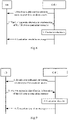
- a first method for a random access includes the following operations.
- Operation 601 a user equipment determines a dedicated contention resource pool for a random access when accessing a cell.
- Operation 602 the user equipment transmits identification information of the user equipment to the cell over a resource in the dedicated contention resource pool for a random access.
- Operation 603 the user equipment receives a contention resolution message from the cell, and determines whether the random access succeeds, according to the contention resolution message.
- the user equipment determines the dedicated contention resource pool for a random access to the cell as follows.
- the user equipment determines the dedicated contention resource pool for a random access according to first resource information broadcasted by the cell.
- the user equipment determines the dedicated contention resource pool for a random access according to the first resource information broadcasted by the cell as follows: the user equipment determines a plurality of dedicated contention resource pools for a random access according to the first resource information broadcasted by the cell, and selects one of the dedicated contention resource pools for a random access.
- the user equipment transmits the identification information of the user equipment to the cell over the resource in the dedicated contention resource pool for a random access as follows: the user equipment transmits the identification information of the user equipment to the cell over the resource in the dedicated contention resource pool for a random access based upon downlink timing of the cell.
- the identification information of the user equipment will be a CCCH SDU; and if the random access is intended for uplink synchronization, then the identification information of the user equipment will be a C-RNTI MAC CE.
- the user equipment determines whether the random access succeeds, according to the contention resolution message as follows: if a CCCH SDU in the contention resolution message is a CCCH SDU transmitted to the cell, then the user equipment will determine that the random access succeeds; otherwise, determine that the random access fails; and if the contention resolution message includes a PDCCH addressed using a C-RNTI MAC CE transmitted to the cell, then the user equipment will determine that the random access succeeds; otherwise, determine that the random access fails.
- the method further includes: if the capacity of the determined dedicated contention resource pool for a random access is greater than a first threshold, then the user equipment will transmit BSR information, and/or a part or all of data to be transmitted, to the cell.
- the user equipment receives the contention resolution message as follows: if the random access of the user equipment is intended for an initial access or to reestablish an RRC connection, then the user equipment will receive the contention resolution message over a resource pool corresponding to second resource information broadcasted by the cell, or receive the contention resolution message over a resource scheduled using a CB-RNTI; and if the random access of the user equipment is for uplink synchronization, then the user equipment will receive the contention resolution message over a PDSCH resource scheduled by a PDCCH addressed using a C-RNTI.
- the method further includes: if the user equipment does not receive the contention resolution message in a contention resolution time window, then the user equipment will reselect a dedicated contention resource pool for a random access, and initiate a random access again, after waiting for a period of time randomly.
- the cell which is an executor of a method is equivalent to a network-side device managing cells.
- a second method for a random access includes the following operations.
- Operation 701 a cell broadcasts first resource information for determining a dedicated contention resource pool for a random access.
- Operation 702 the cell receives identification information of a user equipment, transmitted by the user equipment to access the cell managed by the network-side device, over the dedicated contention resource pool for a random access corresponding to the information about the dedicated contention resource pool for a random access.
- Operation 703 the cell transmits a contention resolution message to the user equipment upon reception of the identification information of the user equipment.
- the user equipment determines whether the random access succeeds, according to the contention resolution message as follows.
- a CCCH SDU in the contention resolution message is a CCCH SDU transmitted to the cell
- the user equipment will determine that the random access succeeds; otherwise, it will determine that the random access fails
- the contention resolution message includes a Physical Downlink Control Channel (PDCCH) addressed based upon a C-RNTI MAC CE transmitted to the cell
- PDCCH Physical Downlink Control Channel
- the method further includes: if the user equipment makes an initial access or establishes an RRC connection, then the cell will allocate a C-RNTI for the user equipment.
- the method further includes: if the radius of the cell is greater than a second threshold, then the cell will configure uplink TA available in the cell for the user equipment.
- the contention resolution message will include the identification information of the user equipment; and if the random access of the user equipment is intended for uplink synchronization, then the contention resolution message will be PDCCH scheduling information, including an initial transmission uplink grant, for a C-RNTI of the user equipment.
- the cell transmits the contention resolution message to the user equipment as follows.
- the cell will transmit the contention resolution message to the user equipment over a resource pool corresponding to second resource information broadcasted by the cell, or transmit the contention resolution message to the user equipment over a resource scheduled using a CB-RNTI; and if the random access of the user equipment is intended for uplink synchronization, then the cell will transmit the contention resolution message to the user equipment over a PDSCH resource scheduled by a PDCCH addressed using a C-RNTI.
- the cell broadcasts the first resource information for determining the dedicated contention resource pool for a random access as follows: the cell broadcasts the first resource information in an SIB; here the SIB is a new SIB different from that in the existing 3GPP TS 36.331, or an SIB obtained by extending the SIB in the 3GPP TS 36.331.
- a UE makes an initial access or reestablishes an RRC connection (a contention based random access).
- the UE makes an initial access to a cell for the purpose of obtaining a C-RNTI and establishing/reestablishing an RRC connection.
- a method for making an initial access or reestablishing an RRC connection includes the following operations:
- a cell 1 broadcasts resource information for determining a dedicated contention resource pool for a random access, via system information.
- the resource information includes a time-frequency position corresponding to the dedicated contention resource pool for a random access, an allowable MCS level, and a priority.
- a UE to access the cell 1 reads the broadcasted message, and obtains the resource information (e.g., the time-frequency position, the MCS, etc.). If there are a plurality of resource pools configured, then the UE may further select one of the dedicated contention resource pools for a random access according to their corresponding priorities. Then the UE transmits identification information of the UE using the selected dedicated contention resource pool for a random access based upon downlink timing of the cell to which a random access is to be initiated.
- the resource information e.g., the time-frequency position, the MCS, etc.
- the identification information of the UE may be a CCCH SDU, or another form of identification information of the UE. What is carried in the CCCH SDU may vary with what the random access is intended for. For example, if the access is intended for an initial access, then the CCCH SDU will carry an RRC Connection Establish Request message; and if the access is intended to reestablish an RRC connection, then the CCCH SDU will carry an RRC Connection Reestablish Request message.
- the UE may further carry BSR information, and/or a part or all of data to be transmitted, while transmitting the identification information of the UE.
- the cell 1 makes a contention decision, that is, if the cell 1 receives the identification information of the UE transmitted by the UE in the operation 2, then it will determine that the UE succeeds in contention.
- the cell 1 For the initial access and the RRC connection reestablish, if the cell 1 determines that the UE succeeds in contention, then it will allocate a C-RNTI for the UE.
- the cell may further determine the TA of the UE upon determining that the UE succeeds in contention.
- the cell 1 transmits a contention resolution message to the UE.
- the contention resolution message may include the identification information of the UE transmitted by the UE over a dedicated contention resource for a random access in the operation 2.
- the contention resolution message may be transmitted in the following two options.
- the resource over which the contention resolution message is transmitted is a transmission resource corresponding to a second resource message broadcasted by the cell.
- Opt2 A CB-RNTI is introduced, and used by the cell to schedule the resource over which the contention resolution message is transmitted.
- the UE listens to the contention resolution message in a time window configured by an eNB at the resource position of the dedicated contention resource pool for a random access broadcasted by the cell, or the resource position, at which the contention resolution message is transmitted, scheduled by the CB-RNTI, and if the contention resolution message including the identification information of the UE is received, then it will determine that it succeeds in contention. If the time window expires, then it will determine that it fails with contention, and attempt at a random access again as in the operations 2 to 4.
- a UE makes a random access for UL synchronization (a contention based random access).
- the UE makes an initial access to a cell for the purpose of UL synchronization, and this scenario is applicable to the case in which the UE has uplink data to be transmitted, but there is out of synchronization in the UL.
- a method for making an initial access for UL synchronization includes the following operations.
- a cell 1 broadcasts resource information for determining a dedicated contention resource pool for a random access, via system information.
- the resource information may include a time-frequency position corresponding to the dedicated contention resource pool for a random access., an allowable MCS level, and a priority.
- a UE to access the cell 1 reads the broadcasted message, and obtains the resource information (e.g., the time-frequency position, the MCS, etc.). If there are a plurality of resource pools configured, then the UE may further select one of the dedicated contention resource pools for a random access according to their corresponding priorities. Then the UE transmits identification information of the UE using the selected dedicated contention resource pool for a random access based upon downlink timing of the cell to which a random access is to be initiated.
- the resource information e.g., the time-frequency position, the MCS, etc.
- the identification information of the UE may be a C-RNTI MAC CE, or another form of identification information of the UE.
- the UE may further carry BSR information, and/or a part or all of data to be transmitted, while transmitting the identification information of the UE.
- the cell 1 makes a contention decision, that is, if the cell 1 receives the identification information of the UE transmitted by the UE in the operation 2, then it will determine that the UE succeeds in contention.
- the cell 1 transmits a contention resolution message to the UE.
- the contention resolution message may be PDCCH scheduling information, including an initial UL grant, for the UE C-RNTI.
- the contention resolution message is scheduled by a PDCCH addressed using the C-RNTI, so the transmission resource may be any PDSCH resource.
- the cell 1 may carry an uplink TA of the UE available in the cell in the contention resolution message and transmit it to the UE; or the UE 1 may subsequently transmit the uplink TA to the UE using the C-RNTI.
- a second system for a random access includes a user equipment 1000, a target network-side device 1010, and a source network-side device 1020.
- the user equipment 1000 is configured to obtain second resource information through the source network-side device managing a source cell when it needs to be switched; determine an uplink transmission dedicated resource allocated for the user equipment by the target network-side device managing a target cell, according to the second resource information; and access the target cell over the uplink transmission dedicated resource.
- the target network-side device 1010 is configured to allocate the uplink transmission dedicated resource for the user equipment to be switched; and notify the source cell of the allocated uplink transmission dedicated resource.
- the source network-side device 1020 is configured to transmit a Handover Request message to the target cell when the user equipment needs to be switched, and notify the user equipment of the uplink transmission dedicated resource allocated by the target cell for the user equipment.
- the target network-side device receives the Handover Request message from the source cell, then it will allocate the uplink transmission dedicated resource for the user equipment to be switched.
- the target network-side device notifies the source cell of the second resource information corresponding to the allocated uplink transmission dedicated resource via an X2 interface.
- the target network-side device may put the second resource information corresponding to the allocated uplink transmission dedicated resource in a Handover Request Acknowledge message, and transmit it to the source cell.
- the source network-side device notifies the user equipment of the second resource information corresponding to the uplink transmission dedicated resource allocated by the target cell for the user equipment.
- the source cell notifies the user equipment of the uplink transmission dedicated resource allocated by the target cell for the user equipment via an RRC Reconfigure message including mobility control information.
- the user equipment obtains the second resource information via the RRC Reconfigure message transmitted by the source cell.
- the user equipment determines the uplink transmission dedicated resource according to the second resource information after obtaining the second resource information, and transmits an RRC Reconfigure Complete message to the target cell over the uplink transmission dedicated resource.
- the target network-side device may further configure an uplink TA available in the cell for the user equipment upon determining that the user equipment succeeds in contention.
- the second threshold here may be determined empirically, as a result of simulation, as demanded, etc.
- the second threshold may be set to the size of a TA adjustment step.
- the size of a TA adjustment step is 78m.
- the target cell notifies the user equipment of the uplink TA of the user equipment in the target cell over a PDCCH addressed based upon a C-RNTI of the UE upon reception of the RRC Reconfigure Complete message transmitted by the user equipment.
- both the target cell and the source cell may be managed by the same network-side device, so both the target network-side device and the source network-side device according to the embodiments of the invention may also be the same network-side device.
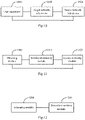
- a third user equipment includes: an obtaining module 1100 configured to obtain second resource information over a source cell when the user equipment needs to be switched; a second determining module 1110 configured to determine an uplink transmission dedicated resource allocated by a target cell for the user equipment, according to the second resource information; and a second accessing module 1120 configured to access the target cell over the uplink transmission dedicated resource.
- the obtaining module 1100 is configured to obtain the second resource information in an RRC Reconfigure message transmitted by the source cell.
- the second accessing module 1120 is configured to: transmit an RRC Reconfigure Complete message to the target cell over the uplink transmission dedicated resource.
- the user equipment may make a contention based random access or a non-contention based random access in different scenarios, the user equipment in Fig.2 , and the user equipment in Fig.11 may be integrated into the same user equipment.
- a third network-side device includes: an allocating module 1200 configured to allocate an uplink transmission dedicated resource for a user equipment to be switched; and a second transmitting module 1210 configured to notify a source cell of the allocated uplink transmission dedicated resource so that the source cell notifies the user equipment of the uplink transmission dedicated resource, and the user equipment accesses a target cell over the uplink transmission dedicated resource.
- the allocating module 1200 is configured to allocate the uplink transmission dedicated resource for the user equipment to be switched, upon reception of a Handover Request message from the source cell.
- the second transmitting module 1210 is configured to notify the source cell of second resource information corresponding to the allocated uplink transmission dedicated resource via an X2 interface.
- the second transmitting module 1210 is configured: T to notify the source cell of allocated uplink transmission dedicated resource via a Handover Request Acknowledge message.
- the second transmitting module 1210 is further configured: after notifying the source cell of the allocated uplink transmission dedicated resource, notify the user equipment of an uplink TA of the user equipment in the target cell over a PDCCH addressed based upon a C-RNTI of the UE upon reception of an RRC Reconfigure Complete message transmitted by the user equipment.
- a fourth network-side device includes: a third transmitting module 1300 configured to transmit a Handover Request message to a target cell when a user equipment needs to be switched; and a fourth transmitting module 1310 configured to notify the user equipment of an uplink transmission dedicated resource allocated by the target cell for the user equipment so that the user equipment accesses the target cell over the uplink transmission dedicated resource.
- the fourth transmitting module 1310 is configured to notify the user equipment of the uplink transmission dedicated resource allocated by the target cell for the user equipment via an RRC Reconfigure message including mobility control information.
- both the source cell and the target cell may be managed by the same network-side device, so both the network-side device in Fig.12 , and the network-side device in Fig.13 according to the examples of the invention may be the same network-side device.
- the network-side device may make a random access in a contention based mode, or may make a random access in a non-contention based mode, in different scenarios, so the network-side device in Fig.3 , and the network-side device in Fig.12 according to the examples of the invention may be integrated into the same network-side device; the network-side device in Fig.3 , and the network-side device in Fig.13 may be integrated into the same network-side device; and the network-side device in Fig.3 , the network-side device in Fig.12 , and the network-side device in Fig.13 may be integrated into the same network-side device.
- a fourth user equipment includes: a processor 1401 configured to read programs in a memory 1404 to: obtain through a transceiver 1402 second resource information over a source cell when the user equipment needs to be switched; determine an uplink transmission dedicated resource allocated by a target cell for the user equipment, according to the second resource information; and access the target cell over the uplink transmission dedicated resource through the transceiver 1402; and the transceiver 1402 configured to be controlled by the processor 1401 to receive and transmit data.
- the processor 1401 is configured to obtain the second resource information in an RRC Reconfigure message transmitted by the source cell.
- the processor 1401 is configured to transmit an RRC Reconfigure Complete message to the target cell over the uplink transmission dedicated resource.
- the bus architecture is represented as a bus 1400, and the bus 1400 may include any number of interconnecting buses and bridges to particularly link together various circuits including one or more processors represented by the processor 1401, and one or more memories represented by the memory 1404.
- the bus 1400 may further link together various other circuits, e.g., peripheral devices, manostats, power management circuits, etc., all of which are well known in the art, so a further description thereof will be omitted in this context.
- the bus interface 1403 serves as an interface between the bus 1400 and the transceiver 1402.
- the transceiver 1402 may be a number of elements including a transmitter and a receiver which are units for communication with various other devices over a transmission medium.
- the transceiver 1402 receives external data from another device.
- the transceiver 1402 is configured transmit data processed by the processor 1401 to the other device.
- a user interface 1405 e.g., a keypad, a display, a speaker, a microphone, a joystick, etc.
- the processor 1401 is responsible for managing the bus 1400 and performing normal processes, e.g., running a general operating system, and the memory 1404 may be configured to store data used by the processor 1401 to perform the operations.
- the processor 1401 may be a CPU, an ASIC, an FPGA, or a CPLD.
- the user equipment may make a contention based random access or a non-contention based random access in different scenarios, the user equipment in Fig.4 , and the user equipment in Fig.14 may be integrated into the same user equipment.
- a fifth network-side device includes: a processor 1501 configured to read programs in a memory 1504 to: allocate an uplink transmission dedicated resource for a user equipment to be switched; and notify through a transceiver 1502 a source cell of the allocated uplink transmission dedicated resource so that the source cell notifies the user equipment of the uplink transmission dedicated resource, and the user equipment accesses a target cell over the uplink transmission dedicated resource; and he transceiver 1502 configured to be controlled by the processor 1501 to receive and transmit data.
- the processor 1501 is configured to: allocate the uplink transmission dedicated resource for the user equipment to be switched, upon reception of a Handover Request message from the source cell.
- the processor 1501 is configured to: notify the source cell of second resource information corresponding to the allocated uplink transmission dedicated resource via an X2 interface.
- the processor 1501 is configured to: notify the source cell of second resource information corresponding to the allocated uplink transmission dedicated resource via a Handover Request Acknowledge message.
- the processor 1501 is further configured: after notifying the source cell of the allocated uplink transmission dedicated resource, to notify the user equipment of an uplink TA of the user equipment in the target cell over a PDCCH addressed based upon a C-RNTI of the UE upon reception of an RRC Reconfigure Complete message transmitted by the user equipment.
- the bus architecture is represented as a bus 1500, and the bus 1500 may include any number of interconnecting buses and bridges to particularly link together various circuits including one or more processors represented by the processor 1501, and one or more memories represented by the memory 1504.
- the bus 1500 may further link together various other circuits, e.g., peripheral devices, manostats, power management circuits, etc., all of which are well known in the art, so a further description thereof will be omitted in this context.
- the bus interface 1503 serves as an interface between the bus 1500 and the transceiver 1502.
- the transceiver 1502 may be a number of elements including a transmitter and a receiver which are units for communication with various other devices over a transmission medium. Data processed by the processor 1501 are transmitted over the transmission medium through an antenna 1505, and furthermore the antenna 1505 further receives and transmits data to the processor 1501.
- the processor 1501 is responsible for managing the bus 1500 and performing normal processes, and may further provide various functions including timing, a peripheral interface, voltage regulation, power supply management, and other control functions, and the memory 1504 may be configured to store data for use by the processor 1501 in performing the operations.
- the processor 1501 may be a CPU, an ASIC, an FPGA, or a CPLD.
- a sixth network-side device includes: a processor 1601 configured to read programs in a memory 1604 to: transmit through a transceiver 1602 a Handover Request message to a target cell when a user equipment needs to be switched; and notify through the transceiver 1602 the user equipment of an uplink transmission dedicated resource allocated by the target cell for the user equipment so that the user equipment accesses the target cell over the uplink transmission dedicated resource; and the transceiver 1602 configured to be controlled by the processor 1601 to receive and transmit data.
- the processor 1601 is configured to notify the user equipment of the uplink transmission dedicated resource allocated by the target cell for the user equipment via an RRC Reconfigure message including mobility control information.
- the bus architecture is represented as a bus 1600, and the bus 1600 may include any number of interconnecting buses and bridges to particularly link together various circuits including one or more processors represented by the processor 1601, and one or more memories represented by the memory 1604.
- the bus 1600 may further link together various other circuits, e.g., peripheral devices, manostats, power management circuits, etc., all of which are well known in the art, so a further description thereof will be omitted in this context.
- the bus interface 1603 serves as an interface between the bus 1600 and the transceiver 1602.
- the transceiver 1602 may be a number of elements including a transmitter and a receiver which are units for communication with various other devices over a transmission medium. Data processed by the processor 1601 are transmitted over the transmission medium through an antenna 1605, and furthermore the antenna 1605 further receives and transmits data to the processor 1601.
- the processor 1601 is responsible for managing the bus 1600 and performing normal processes, and may further provide various functions including timing, a peripheral interface, voltage regulation, power supply management, and other control functions, and the memory 1604 may be configured to store data used by the processor 1601 to perform the operations.
- the processor 1601 may be a CPU, an ASIC, an FPGA, or a CPLD.
- both the source cell and the target cell may be managed by the same network-side device, so both the network-side device in Fig.15 , and the network-side device in Fig.16 according to the examples of the invention may be the same network-side device.
- the network-side device may make a random access in a contention based mode, or may make a random access in a non-contention based mode, in different scenarios, so the network-side device in Fig.5 , and the network-side device in Fig.15 according to the examples of the invention may be integrated into the same network-side device; the network-side device in Fig.5 , and the network-side device in Fig.16 may be integrated into the same network-side device; and the network-side device in Fig.5 , the network-side device in Fig.15 , and the network-side device in Fig.16 may be integrated into the same network-side device.
- examples of the invention further provide methods for a random access, and since devices corresponding to the methods are the devices in the system for a random access according to the examples of the invention, and the methods address the problem under a similar principle to that of the system, reference may be made to the implementations of the devices for implementations of the methods, so a repeated description thereof will be omitted here.
- a third method for a random access includes the following operations.
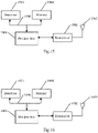
- Operation 1700 a user equipment to be switched obtains second resource information over a source cell.
- Operation 1701 the user equipment determines an uplink transmission dedicated resource allocated by a target cell for the user equipment, according to the second resource information.
- Operation 1702 the user equipment accesses the target cell over the uplink transmission dedicated resource.
- the user equipment obtains the second resource information over the source cell includes: the user equipment obtains the second resource information in an RRC Reconfigure message transmitted by the source cell.
- the user equipment accesses the target cell over the uplink transmission dedicated resource includes: the user equipment transmits an RRC Reconfigure Complete message to the target cell over the uplink transmission dedicated resource.
- the target cell which is an executor of a method is equivalent to a network-side device managing the target cell.
- a fourth method for a random access includes the following operations.
- Operation 1800 a target cell determines an uplink transmission dedicated resource for a user equipment to be switched.
- the target cell notifies a source cell of the allocated uplink transmission dedicated resource so that the source cell notifies the user equipment of the uplink transmission dedicated resource, and the user equipment accesses the target cell over the uplink transmission dedicated resource.
- the method further includes: the target cell receives a Handover Request message from the source cell.
- the target cell notifies the source cell of the allocated uplink transmission dedicated resource includes: the target cell notifies the source cell of second resource information corresponding to the allocated uplink transmission dedicated resource via an X2 interface.
- the target cell notifies the source cell of the allocated uplink transmission dedicated resource includes: the target cell notifies the source cell of the allocated uplink transmission dedicated resource via a Handover Request Acknowledge message.
- the method further includes: the target cell notifies the user equipment of an uplink TA in the target cell over a PDCCH addressed based upon a C-RNTI of the UE upon reception of an RRC Reconfigure Complete message transmitted by the user equipment.
- the source cell which is an executor of a method is equivalent to a network-side device managing the source cell.
- a fifth method for making a random access includes the following operations.
- Operation 1900 a source cell transmits a Handover Request message to a target cell when a user equipment needs to be switched.
- Operation 1901 the source cell notifies the user equipment of an uplink transmission dedicated resource allocated by a target cell for the user equipment so that the user equipment accesses the target cell over the uplink transmission dedicated resource.
- the source cell notifies the user equipment of the uplink transmission dedicated resource allocated by the target cell for the user equipment includes: the source notifies the user equipment of the uplink transmission dedicated resource allocated by the target cell for the user equipment via an RRC Reconfigure message including mobility control information.
- a method for a non-contention based random access includes the following operations.
- a target cell allocates an uplink transmission dedicated resource for a UE to be switched upon reception of a Handover Request message transmitted by a source cell, so that the UE accesses a target cell in initial uplink transmission.
- the target cell encapsulates information about the uplink transmission dedicated resource determined for the UE in a Target eNB to Source eNB Transparent Container in a Handover Request Acknowledge message transmitted to the source cell.
- the source cell transmits to the UE an RRC Reconfigure message, including mobility control information, which includes the information about the uplink transmission dedicated resource allocated by the target cell for the UE to access the target cell.
- the UE determines the uplink transmission dedicated resource corresponding to the information in the received RRC Reconfigure message received from the source cell, and transmits an RRC Reconfigure Complete message to the target cell over the uplink transmission dedicated resource based upon downlink timing of the target cell to thereby access the target cell.
- the target cell will transmit an uplink TA of the UE in the target cell over a PDCCH addressed based upon a C-RNTI of the UE upon reception of the RRC Reconfigure Complete message transmitted by the UE.
- a second threshold e.g., the size of a TA adjustment step (78m)
- the user equipment transmits the identification information of the user equipment to the cell over the resource in the dedicated contention resource pool for a random access; and if the user equipment receives the contention resolution message from the cell, then it will determine whether the random access succeeds, according to the contention resolution message.
- the user equipment determines the uplink transmission dedicated resource allocated by the target cell for the user equipment, according to the second resource information; and accesses the target cell over the uplink transmission dedicated resource.
- the number of interaction stages in the random access procedure may be reduced to thereby shorten a delay of the random access, so that it can be applied to a scenario having a strict requirement of delay.
Description
- This application claims the benefit of
Chinese Patent Application No. 201510312744.1, filed with the Chinese Patent Office on June 9, 2015 - The present invention relates to the field of random access, and particularly to a method and device for a random access.
- A random access in a Long Term Evolution (LTE) system is categorized into a non-contention based random access and a contention based random access. These two random access procedures will be introduced below respectively.
- A procedure of a non-contention based random access generally includes three steps.
- 1. An eNB allocates for a User Equipment (UE) a dedicated Random Access Preamble (ra-PreambleIndex) for a non-contention based random access, and a Physical Random Access Channel (PRACH) resource for a random access;
- 2. The UE transmits a specified dedicated preamble to the eNB over the specified PRACH resource according to the indicated ra-PreambleIndex, and the PRACH resource for a random access. The eNB calculates an uplink Timing Advance (TA) upon reception of the preamble.
- 3. The eNB transmits to the UE a random access response, the random access response including information about the timing advance, and a subsequent uplink transmission resource allocation uplink grant, where a timing relationship for subsequent uplink transmission by the UE is defined according to the timing advance.
- A procedure of a contention based random access generally includes four steps.
- 1. A UE selects a random access preamble and a PRACH resource, and transmits the selected random access preamble to an eNB over the PRACH resource.
- 2. The eNB receives the preamble, calculates a Timing Advance (TA), and transmits to the UE a random access response, random access response at least including information about the timing advance, and an UL grant.
- 3. The UE transmits uplink data over the specified UL grant.
- 4. A contention resolution message is transmitted, and the UE may determine according to the Msg4 whether the random access succeeds.
- A small cell may be provided with a deployed hotspot in a high frequency band (e.g., 5.9GHz) in a future communication system (e.g., a 5G system).
- There may be the following operating modes of the small cell in the high-frequency band.
- In a first mode which is a standalone mode, the cell may operate as a standalone cell to allow a UE to access and reside separately.
- In a second mode which is a non-standalone mode, the cell operates only as a resource, and does not allow a UE to access and reside separately.
- There are so many interaction stages in the existing random access procedure that may increase a delay of the random access, thus failing to accommodate an application scenario of the small cell at high frequencies.
- In summary, there is such a long delay in the existing random access procedure that hinders it from being applied to a scenario having a strict requirement of delay.
- Document
WO2015/119555A1 published on 13. 08. 2015 claims the priority date of 06. 02. 2014 and falls under Art. 54(3) EPC, and discloses methods and apparatus for providing a Random Access procedure used by a communications device and an access node, for example the UE (user equipment) and eNodeB (the LTE radio basestation) in an LTE network, to e.g. establish a Radio Resource Control (RRC) connection. An example of a method according to the invention for use in an access node comprises: receiving signals comprising multiple instances of an uplink Random Access message; spatially resolving the received signals to identify directions from which the uplink Random Access message was received; and transmitting distinct downlink Random Access messages in the identified directions from which the uplink Random Access message was received. - Document
US2012/0008524A1 discloses a user equipment for obtaining data for observing performance related to Random Access in a cellular radio system is provided. The user equipment can connect to the system. In order to provide the network/system with data for observing the random access procedure the user equipment measures and stores data needed to compute measurements to be reported to the system. The user equipment further generates a measurement report, and transmits the measurement report based on a trigger event. - Document, titled Scattering Random-Access Intensity in LTE, discloses four effective eNB selection algorithms to estimate the access intensity of an eNB. Simulation results show that the proposed algorithms perform better than conventional approach.
- Document
US2015/0105084A1 discloses a method at a user equipment for handover from a serving cell to a target cell, the method sending a measurement report to the serving cell; and transmitting a reconfiguration complete message to the target cell; wherein the measurement report includes downlink timing measurements for the target cell. Further, a method at a source network element for handover of a user equipment from the source network element to a target network element, the method receiving a measurement report from the user equipment; sending a handover request to the target network element; receiving a handover request acknowledgement from the target network element, the handover request acknowledgement including a reconfiguration message and at least one downlink subframe in which an uplink grant is expected at the target network element for the user equipment; and forwarding the reconfiguration message and at least one downlink subframe to the user equipment. - Document, titled Non contention based HO (R2-071253; R2-070455), compares the non-contention based HO procedure with transmission of UE specific signatures on RACH. As it was shown in the discussion non-contention based HO procedure especially implemented with PDCCH allocation method can provide predictable, shorter U-plane delay and easier NW planning than using normal RACH for TA acquisition in case of HO.
- Document, titled RACH-less Handover in synchronized networks (R2-072655), discloses in case of a well-defined time relation between uplink and downlink time frames, the HO procedure can be significantly simplified for synchronized eNBs. In particular the RACH access and the signalling of the TA become dispensable. For this purpose it would be necessary to agree on one fixed time relation between uplink and downlink for a given synchronized network or on a set of fixed time relations from which one relation can be signalled to the UE directly or via broadcast. Moreover, the UE would need to be instructed to use the RACH-less HO.
- Document
US2014/0334389A1 discloses a wireless access network node receives, from a user equipment (UE), information relating to a random access procedure. The wireless access network node sends, to the UE, an indication to stop the random access procedure, based on the received information. - Document, titled RACH Message Structure (R2-060821; R2-060377) discloses some use cases for RACH and possible content of the RACH message. About 30 bits need to be carried. The length of the message could be constant, as shown in Table 1, but the physical layer may not require this. lt is proposed that RACH is used to inform the network of the establishment cause. lt is also proposes that RACH message should also carry an uplink shared channel capacity request to help the scheduler in LTE_ACTIVE.
- Document, titled Initial, Random Access and Identity Handling (R2-060592), discloses efficient contention resolution and identity handling enables the separation of data transmissions from the random access channel while maintaining low latency. This is desirable since the efficiency of contention based transmissions is quite limited. The proposed solution makes all data transmissions in a contention free (scheduled) fashion.
- Embodiments of the invention provide a method and device for a random access so as to address the problem in the prior art that there is such a long delay in a random access procedure that hinders it from being applied to a scenario having a strict requirement of delay. The invention is set out in the appended set of claims.
-
-
Fig.1 is a schematic structural diagram of a first system for a random access according to an embodiment of the invention. -
Fig.2 is a schematic structural diagram of a first user equipment according to an embodiment of the invention. -
Fig.3 is a schematic structural diagram of a first network-side device according to an embodiment of the invention. -
Fig.4 is a schematic structural diagram of a second user equipment according to an embodiment of the invention. -
Fig.5 is a schematic structural diagram of a second network-side device according to an embodiment of the invention. -
Fig.6 is a schematic flow chart of a first method for a random access according to an embodiment of the invention. -
Fig.7 is a schematic flow chart of a second method for a random access according to an embodiment of the invention. -
Fig.8 is a schematic flow chart of a method for an initial access or reestablishing an RRC connection according to an embodiment of the invention. -
Fig.9 is a schematic flow chart of a method for a random access in UL synchronization according to an embodiment of the invention. -
Fig. 10 is a schematic structural diagram of a second system for a random access according to an embodiment of the invention. -
Fig.11 is a schematic structural diagram of a third user equipment according to an embodiment of the invention. -
Fig.12 is a schematic structural diagram of a third network-side device according to an embodiment of the invention. -
Fig.13 is a schematic structural diagram of a fourth network-side device according to an embodiment of the invention. -
Fig. 14 is a schematic structural diagram of a fourth user equipment according to an embodiment of the invention. -
Fig. 15 is a schematic structural diagram of a fifth network-side device according to an embodiment of the invention. -
Fig.16 is a schematic structural diagram of a sixth network-side device according to an embodiment of the invention. -
Fig.17 is a schematic flow chart of a third method for a random access according to an embodiment of the invention. -
Fig.18 is a schematic flow chart of a fourth method for a random access according to an embodiment of the invention. -
Fig. 19 is a schematic flow chart of a fifth method for a random access according to an embodiment of the invention. -
Fig.20 is a schematic flow chart of a method for a non-contention based random access according to an embodiment of the invention. - In a contention based random access procedure according to the embodiments of the invention, a user equipment transmits identification information of the user equipment to a cell over a resource in a dedicated contention resource pool for a random access; and if the user equipment receives a contention resolution message from the cell, then it will determine whether the random access succeeds according to the contention resolution message. In a non-contention based random access procedure according to the embodiments of the invention, a user equipment determines an uplink transmission dedicated resource allocated by a target cell for the user equipment, according to second resource information; and accesses the target cell over the uplink transmission dedicated resource. The number of interaction stages in the random access procedure can be reduced to thereby shorten a delay of the random access, so that it can be applied to a scenario having a strict requirement of delay.
- The embodiments of the invention provide two random access solutions, i.e., a contention based random access solution and a non-contention based random access solution.
- Here reference may be made to
Fig.1 to Fig.9 for the contention based random access solution, and reference may be made toFig. 10 to Fig.19 for the non-contention based random access solution. - The embodiments of the invention will be described below in further details with reference to the drawings.
- As illustrated in
Fig.1 , a first system for a random access according to an embodiment of the invention includes auser equipment 10, and a network-side device 20 managing cells. - The
user equipment 10 is configured determine a dedicated contention resource pool for a random access when accessing a cell; transmit identification information of the user equipment to the cell over a resource in the dedicated contention resource pool for a random access; and receive a contention resolution message from the cell, and determine whether the random access succeeds, according to the contention resolution message. - The network-side device 20 is configured to broadcast first resource information for determining the dedicated contention resource pool for a random access; receive the identification information of the user equipment transmitted by the user equipment to access the cell managed by the network-side device, over the dedicated contention resource pool for a random access corresponding to the information about the dedicated contention resource pool for a random access; and transmit the contention resolution message to the user equipment.
- If the network-side device receives the identification information of the user equipment, then it will determine that the corresponding user equipment succeeds in contention, and transmit the contention resolution message to the corresponding user equipment.
- Correspondingly if the user equipment receives the contention resolution message, then it will determine that the random access succeeds.
- In an implementation, the network-side device broadcasts the first resource information corresponding to at least one dedicated contention resource pool for a random access in the managed cell, and the UE to access the cell firstly reads the broadcasted message and obtains the first resource information, and then transmits the identification information of the UE over the resource in the dedicated contention resource pool for a random access corresponding to the first resource information. If the network-side device receives the identification information of the UE successfully, then it will determine that the UE succeeds in contention, and transmit the contention resolution message to the UE.
- In an example of the invention, the first resource information for determining the dedicated contention resource pool for a random access is broadcasted by the cell by broadcasting the first resource information in an SIB.
- Here the SIB is a new SIB different from that in the existing 3GPP TS 36.331, or a System Information Block (SIB) obtained by extending the SIB in the 3rd Generation partnership Project (3GPP) Technical Specification (TS) 36.331.
- Here the first resource information includes but will not be limited to a part or all of the following information: a time-frequency position corresponding to the dedicated contention resource pool for a random access, an allowable Modulation and Coding Scheme (MCS) level, and a priority.
- The user equipment may determine the dedicated contention resource pool for a random access according to the time-frequency resources upon reception of the first resource information which is broadcasted.
- If there are a plurality of dedicated contention resource pools for a random access, then the user equipment may determine the corresponding dedicated contention resource pools for a random access according to the respective time-frequency positions.
- If there is an MCS level, then the user equipment may determine a modulation and coding scheme for transmitting the identification information of the user equipment, according to the MCS level.
- If there are a plurality of dedicated contention resource pools for a random access, then the user equipment may select a dedicated contention resource pool for a random access with the highest priority according to the priorities corresponding to the respective dedicated contention resource pools for a random access.
- In an implementation, after the dedicated contention resource pool for a random access is determined, the user equipment may transmit the identification information of the user equipment to the cell over the resource in the dedicated contention resource pool for a random access based upon downlink timing of the cell. Stated otherwise, the identification information of the user equipment is transmitted to the cell over the resource in the dedicated contention resource pool for a random access at a downlink receive instance of time of the cell.
- Optionally the identification information of the user equipment in the embodiment of the invention may be the following information.
- If the random access is intended for an initial access of the user equipment or to reestablish a Radio Resource Control (RRC) connection by the user equipment, then the identification information of the user equipment will be a Common Control Channel (CCCH) Service Data Unit (SDU); or the identification information of the user equipment may be other information capable of identifying the user equipment.
- If the random access is intended for uplink synchronization, then the identification information of the user equipment will be a Cell Radio Network Temporary Identifier (C-RNTI) Media Access Control (MAC) Control Element (CE); or the identification information of the user equipment may be other information capable of identifying the user equipment.
- Correspondingly the user equipment determines whether the random access succeeds, according to the contention resolution message as follows.
- If a CCCH SDU in the contention resolution message is a CCCH SDU transmitted to the cell, then the user equipment will determine that the random access succeeds; otherwise, it will determine that the random access fails.
- If the contention resolution message includes a Physical Downlink Control Channel (PDCCH) addressed based upon a C-RNTI MAC CE transmitted to the cell, then the user equipment will determine that the random access succeeds; otherwise, it will determine that the random access fails.
- Optionally if the user equipment determines that the random access fails, then it may reselect a dedicated contention resource pool for a random access, and initiate a random access again, after waiting for a period of time randomly.
- In an implementation, the number of attempts at a random access may be set, and before the number of attempts is reached, the random access will be retried until it succeeds; and if the number of attempts is reached, then the random access will be stopped.
- Optionally if the capacity of the dedicated contention resource pool for a random access determined by the user equipment is greater than a first threshold, then the user equipment will transmit Buffer Status Report (BSR) information, and/or a part or all of data to be transmitted, to the cell.
- The first threshold here may be determined empirically, as a result of simulation, as demanded, etc.
- If the user equipment makes an initial access or establishes an RRC connection, then the network-side device may further allocate a C-RNTI for the user equipment upon determining that the user equipment succeeds in contention.
- Optionally the network-side device may allocate the C-RNTI for the user equipment via the contention resolution message; or may allocate the C-RNTI for the user equipment via another message.
- In an implementation, if the radius of the cell is greater than a second threshold, then the network-side device may further configure an uplink TA available in the cell for the user equipment upon determining that the user equipment succeeds in contention.
- The second threshold here may be determined empirically, as a result of simulation, as demanded, etc. For example, the second threshold may be set to the size of a Timing Advance (TA) adjustment step. At present, the size of a TA adjustment step is 78m.
- Optionally the network-side device may allocate the TA for the user equipment via the contention resolution message; or may allocate the TA for the user equipment via another message.
- In an implementation, if the random access of the user equipment is intended for an initial access or to reestablish an RRC connection, then the network-side device may put the received identification information of the user equipment in the contention resolution message. Optionally the network-side device may put the C-RNTI and/or the TA allocated for the user equipment in the contention resolution message.
- If the random access of the user equipment is intended for uplink synchronization, then the network-side device will transmit the contention resolution message to the user equipment over a Physical Downlink Shared Channel (PDSCH) resource scheduled by a PDCCH addressed using a C-RNTI. Optionally the network-side device may further put the TA allocated for the user equipment in the contention resolution message.
- Optionally the network-side device transmits the contention resolution message to the user equipment as follows.
- If the random access of the user equipment is intended for an initial access or to reestablish an RRC connection, then the cell will transmit the contention resolution message to the user equipment over a resource pool corresponding to second resource information broadcasted by the cell, or transmit the contention resolution message to the user equipment over a resource scheduled using a Contention Based Radio Network Temporary Identity (CB-RNTI).
- Correspondingly the user equipment receives the contention resolution message over the resource pool corresponding to the second resource information broadcasted by the cell; or receives the contention resolution message over the resource scheduled using the CB-RNTI.
- Optionally the cell broadcasts the second resource information by broadcasting the second resource information in an SIB.
- Here the SIB is a new SIB different from that in the existing 3GPP TS 36.331, or an SIB obtained by extending the SIB in the 3GPP TS 36.331.
- If the random access of the user equipment is intended for uplink synchronization, then the cell will transmit the contention resolution message to the user equipment over a PDSCH resource scheduled by a PDCCH addressed using a C-RNTI.
- Correspondingly the user equipment receives the contention resolution message over the PDSCH resource scheduled by the PDCCH addressed using the C-RNTI.
- Optionally the network-side device may configure a contention resolution time window for the user equipment via broadcast or dedicated signaling (the dedicated signaling is applicable to the case in which user equipment has established an RRC connection).
- Correspondingly if the user equipment receives the contention resolution message in the contention resolution time window, then it will determine that it succeeds in contention.
- If the user equipment does not receive the contention resolution message in the contention resolution time window, then it will reselect a dedicated contention resource pool for a random access, and initiate a random access again, after waiting for a period of time randomly.
- As illustrated in
Fig.2 , a first user equipment according to an example of the invention includes: a first determiningmodule 200 configured to determine a dedicated contention resource pool for a random access when accessing a cell; afirst transmitting module 201 configured to transmit identification information of the user equipment to the cell over a resource in the dedicated contention resource pool for a random access; and a first accessingmodule 202 configured to receive a contention resolution message from the cell, and determine whether the random access succeeds, according to the contention resolution message. - Optionally the first determining
module 200 is configured to: determine the dedicated contention resource pool for a random access according to first resource information broadcasted by the cell. - Optionally the first determining
module 200 is configured to: determine a plurality of dedicated contention resource pools for a random access according to the first resource information broadcasted by the cell, and select one of the dedicated contention resource pools for a random access. - Optionally the
first transmitting module 201 is configured to: transmit the identification information of the user equipment to the cell over the resource in the dedicated contention resource pool for a random access based upon downlink timing of the cell. - Optionally if the random access is intended for an initial access of the user equipment, or to reestablish an RRC connection by the user equipment, then the identification information of the user equipment will be a CCCH SDU; and If the random access is intended for uplink synchronization, then the identification information of the user equipment will be a C-RNTI MAC CE.
- Optionally the first accessing
module 202 is configured: if a CCCH SDU in the contention resolution message is a CCCH SDU transmitted to the cell, to determine that the random access succeeds; otherwise, to determine that the random access fails; and If the contention resolution message includes a PDCCH addressed using a C-RNTI MAC CE transmitted to the cell, to determine that the random access succeeds; otherwise, to determine that the random access fails. - Optionally the
first transmitting module 201 is configured: upon determining the dedicated contention resource pool for a random access when accessing the cell, if the capacity of the determined dedicated contention resource pool for a random access is greater than a first threshold, to transmit BSR information, and/or a part or all of data to be transmitted, to the cell. - Optionally the first accessing
module 202 is configured: if the random access of the user equipment is intended for an initial access or to reestablish an RRC connection, to receive the contention resolution message over a resource pool corresponding to second resource information broadcasted by the cell, or to receive the contention resolution message over a resource scheduled using a CB-RNTI; and if the random access of the user equipment is for uplink synchronization, to receive the contention resolution message over a PDSCH resource scheduled by a PDCCH addressed using a C-RNTI. - Optionally the first accessing
module 202 is further configured: if the user equipment does not receive the contention resolution message in a contention resolution time window, to trigger the first determining module to reselect a dedicated contention resource pool for a random access, and to initiate a random access again, after waiting for a period of time randomly. - As illustrated in
Fig.3 , a first network-side device according to an example of the invention includes: abroadcasting module 300 configured to broadcast first resource information for determining a dedicated contention resource pool for a random access; afirst receiving module 301 configured to receive identification information of a user equipment, transmitted by the user equipment to access a cell managed by the network-side device, over the dedicated contention resource pool for a random access corresponding to the information about the dedicated contention resource pool for a random access; and afirst transmitting module 302 configured to transmit a contention resolution message to the user equipment upon reception of the identification information of the user equipment. - Optionally the
broadcasting module 300 is configured to broadcast the first resource information in an SIB; here the SIB is a new SIB different from that in the existing 3GPP TS 36.331, or an SIB obtained by extending the SIB in the 3GPP TS 36.331. - Optionally the
first receiving module 301 is further configured: upon reception of the identification information of the user equipment, if the user equipment makes an initial access or establishes an RRC connection, to allocate a C-RNTI for the user equipment. - Optionally the
first receiving module 301 is further configured: upon reception of the identification information of the user equipment, if the radius of the cell is greater than a second threshold, to configure uplink TA available in the cell for the user equipment. - Optionally if the user equipment makes an initial access or establishes an RRC connection, then the contention resolution message will include the identification information of the user equipment; and if the random access of the user equipment is intended for uplink synchronization, then the contention resolution message will be PDCCH scheduling information, including an initial transmission uplink grant, for a C-RNTI of the user equipment.
- Optionally the
first transmitting module 302 is configured: if the random access of the user equipment is intended for an initial access or to reestablish an RRC connection, to transmit the contention resolution message to the user equipment over a resource pool corresponding to second resource information broadcasted by the cell, or to transmit the contention resolution message to the user equipment over a resource scheduled using a CB-RNTI; and if the random access of the user equipment is intended for uplink synchronization, to transmit the contention resolution message to the user equipment over a PDSCH resource scheduled by a PDCCH addressed using a C-RNTI. - Optionally the
broadcasting module 300 is configured to broadcast the second resource information in an SIB; here the SIB is a new SIB different from that in the existing 3GPP TS 36.331, or an SIB obtained by extending the SIB in the 3GPP TS 36.331. - As illustrated in
Fig.4 , a second user equipment according to an example of the invention includes: aprocessor 401 configured to read programs in amemory 404 to: determine a dedicated contention resource pool for a random access when accessing a cell; transmit identification information of the user equipment to the cell over a resource in the dedicated contention resource pool for a random access through atransceiver 402; and receive a contention resolution message from the cell through thetransceiver 402, and determine whether the random access succeeds, according to the contention resolution message; and thetransceiver 402 configured to be controlled by theprocessor 401 to receive and transmit data. - Optionally the
processor 401 is configured to: determine the dedicated contention resource pool for a random access according to first resource information broadcasted by the cell. - Optionally the
processor 401 is configured to: determine a plurality of dedicated contention resource pools for a random access according to the first resource information broadcasted by the cell, and select one of the dedicated contention resource pools for a random access. - Optionally the
processor 401 is configured to: transmit the identification information of the user equipment to the cell over the resource in the dedicated contention resource pool for a random access based upon downlink timing of the cell. - Optionally if the random access is intended for an initial access of the user equipment, or to reestablish an RRC connection by the user equipment, then the identification information of the user equipment will be a CCCH SDU; and if the random access is intended for uplink synchronization, then the identification information of the user equipment will be a C-RNTI MAC CE.
- Optionally the
processor 401 is configured: if a CCCH SDU in the contention resolution message is a CCCH SDU transmitted to the cell, to determine that the random access succeeds; otherwise, to determine that the random access fails; and if the contention resolution message includes a PDCCH addressed using a C-RNTI MAC CE transmitted to the cell, to determine that the random access succeeds; otherwise, to determine that the random access fails. - Optionally the
processor 401 is configured: upon determining the dedicated contention resource pool for a random access when accessing the cell, if the capacity of the determined dedicated contention resource pool for a random access is greater than a first threshold, to transmit BSR information, and/or a part or all of data to be transmitted, to the cell. - Optionally the
processor 401 is configured: if the random access of the user equipment is intended for an initial access or to reestablish an RRC connection, to receive the contention resolution message over a resource pool corresponding to second resource information broadcasted by the cell, or to receive the contention resolution message over a resource scheduled using a CB-RNTI; and if the random access of the user equipment is for uplink synchronization, to receive the contention resolution message over a PDSCH resource scheduled by a PDCCH addressed using a C-RNTI. - Optionally the
processor 401 is further configured: if the user equipment does not receive the contention resolution message in a contention resolution time window, to trigger the first determining module to reselect a dedicated contention resource pool for a random access, and to initiate a random access again, after waiting for a period of time randomly. - In
Fig.4 , the bus architecture is represented as abus 400, and thebus 400 may include any number of interconnecting buses and bridges to particularly link together various circuits including one or more processors represented by theprocessor 401, and one or more memories represented by thememory 404. Thebus 400 may further link together various other circuits, e.g., peripheral devices, manostats, power management circuits, etc., all of which are well known in the art, so a further description thereof will be omitted in this context. Thebus interface 403 serves as an interface between thebus 400 and thetransceiver 402. Thetransceiver 402 may be a number of elements including a transmitter and a receiver which are units for communication with various other devices over a transmission medium. For example, thetransceiver 402 receives external data from another device. Thetransceiver 402 is configured to transmit data processed by theprocessor 401 to the other device. Dependent upon the nature of a computing system, there may be further provided auser interface 405, e.g., a keypad, a display, a speaker, a microphone, a joystick, etc. - The
processor 401 is responsible for managing thebus 400 and performing normal processes, e.g., running a general operating system, and thememory 404 may be configured to store data used by theprocessor 401 to perform the operations. - Optionally the
processor 401 may be a Central Processor (CPU), an Application Specific Integrated Circuit (ASIC), a Field-Programmable Gate Array (FPGA), or a Complex Programmable Logic Device (CPLD). - As illustrated in
Fig.5 , a second network-side device according to an example of the invention includes: aprocessor 501 configured to read programs in amemory 504 to: broadcast first resource information for determining a dedicated contention resource pool for a random access, through atransceiver 502; receive identification information of a user equipment, transmitted by the user equipment to access the cell managed by the network-side device, over the dedicated contention resource pool for a random access corresponding to the information about the dedicated contention resource pool for a random access, through thetransceiver 502; and transmit a contention resolution message to the user equipment through thetransceiver 502 upon reception of the identification information of the user equipment; and thetransceiver 502 configured to be controlled by theprocessor 501 receive and transmit data. - Optionally the
processor 501 is configured to broadcast the first resource information in an SIB; here the SIB is a new SIB different from that in the existing 3GPP TS 36.331, or an SIB obtained by extending the SIB in the 3GPP TS 36.331. - Optionally the
processor 501 is further configured: upon reception of the identification information of the user equipment, if the user equipment makes an initial access or establishes an RRC connection, to allocate a C-RNTI for the user equipment. - Optionally the
processor 501 is further configured: upon reception of the identification information of the user equipment, if the radius of the cell is greater than a second threshold, to configure the user equipment with uplink TA available in the cell. - Optionally if the user equipment makes an initial access or establishes an RRC connection, then the contention resolution message will include the identification information of the user equipment; and if the random access of the user equipment is intended for uplink synchronization, then the contention resolution message will be PDCCH scheduling information, including an initial transmission uplink grant, for a C-RNTI of the user equipment.
- Optionally the
processor 501 is configured: if the random access of the user equipment is intended for an initial access or to reestablish an RRC connection, to transmit the contention resolution message to the user equipment over a resource pool corresponding to second resource information broadcasted by the cell, or to transmit the contention resolution message to the user equipment over a resource scheduled using a CB-RNTI; and if the random access of the user equipment is intended for uplink synchronization, to transmit the contention resolution message to the user equipment over a PDSCH resource scheduled by a PDCCH addressed using a C-RNTI. - Optionally the
processor 501 is configured to broadcast the second resource information in an SIB; here the SIB is a new SIB different from that in the existing 3GPP TS 36.331, or an SIB obtained by extending the SIB in the 3GPP TS 36.331. - In
Fig.5 , the bus architecture is represented as abus 500, and thebus 500 may include any number of interconnecting buses and bridges to particularly link together various circuits including one or more processors represented by theprocessor 501, and one or more memories represented by thememory 504. Thebus 500 may further link together various other circuits, e.g., peripheral devices, manostats, power management circuits, etc., all of which are well known in the art, so a further description thereof will be omitted in this context. Thebus interface 503 serves as an interface between thebus 500 and thetransceiver 502. Thetransceiver 502 may be a number of elements including a transmitter and a receiver which are units for communication with various other devices over a transmission medium. Data processed by theprocessor 501 are transmitted over the transmission medium through anantenna 505, and furthermore theantenna 505 further receives and transmits data to theprocessor 501. - The
processor 501 is responsible for managing thebus 500 and performing normal processes, and may further provide various functions including timing, a peripheral interface, voltage regulation, power supply management, and other control functions, and thememory 504 may be configured to store data used by theprocessor 501 to perform the operations. - Optionally the
processor 501 may be a CPU, an ASIC, an FPGA, or a CPLD. - Based upon the same inventive idea, embodiments of the invention further provide methods for a random access, and since devices corresponding to the methods are the devices in the system for a random access according to the embodiments of the invention, and the methods address the problem under a similar principle to that of the system, reference may be made to the implementations of the devices for implementations of the methods, so a repeated description thereof will be omitted here.
- As illustrated in
Fig.6 , a first method for a random access according to an embodiment of the invention includes the following operations. - Operation 601: a user equipment determines a dedicated contention resource pool for a random access when accessing a cell.
- Operation 602: the user equipment transmits identification information of the user equipment to the cell over a resource in the dedicated contention resource pool for a random access.
- Operation 603: the user equipment receives a contention resolution message from the cell, and determines whether the random access succeeds, according to the contention resolution message.
- The user equipment determines the dedicated contention resource pool for a random access to the cell as follows.
- The user equipment determines the dedicated contention resource pool for a random access according to first resource information broadcasted by the cell.
- Optionally the user equipment determines the dedicated contention resource pool for a random access according to the first resource information broadcasted by the cell as follows: the user equipment determines a plurality of dedicated contention resource pools for a random access according to the first resource information broadcasted by the cell, and selects one of the dedicated contention resource pools for a random access.
- Optionally the user equipment transmits the identification information of the user equipment to the cell over the resource in the dedicated contention resource pool for a random access as follows: the user equipment transmits the identification information of the user equipment to the cell over the resource in the dedicated contention resource pool for a random access based upon downlink timing of the cell.
- Optionally if the random access is intended for an initial access of the user equipment, or to reestablish an RRC connection by the user equipment, then the identification information of the user equipment will be a CCCH SDU; and if the random access is intended for uplink synchronization, then the identification information of the user equipment will be a C-RNTI MAC CE.
- Optionally the user equipment determines whether the random access succeeds, according to the contention resolution message as follows: if a CCCH SDU in the contention resolution message is a CCCH SDU transmitted to the cell, then the user equipment will determine that the random access succeeds; otherwise, determine that the random access fails; and if the contention resolution message includes a PDCCH addressed using a C-RNTI MAC CE transmitted to the cell, then the user equipment will determine that the random access succeeds; otherwise, determine that the random access fails.
- Optionally after the user equipment determines the dedicated contention resource pool for a random access when accessing the cell, the method further includes: if the capacity of the determined dedicated contention resource pool for a random access is greater than a first threshold, then the user equipment will transmit BSR information, and/or a part or all of data to be transmitted, to the cell.
- Optionally the user equipment receives the contention resolution message as follows: if the random access of the user equipment is intended for an initial access or to reestablish an RRC connection, then the user equipment will receive the contention resolution message over a resource pool corresponding to second resource information broadcasted by the cell, or receive the contention resolution message over a resource scheduled using a CB-RNTI; and if the random access of the user equipment is for uplink synchronization, then the user equipment will receive the contention resolution message over a PDSCH resource scheduled by a PDCCH addressed using a C-RNTI.
- Optionally the method further includes: if the user equipment does not receive the contention resolution message in a contention resolution time window, then the user equipment will reselect a dedicated contention resource pool for a random access, and initiate a random access again, after waiting for a period of time randomly.
- In the following description, the cell which is an executor of a method is equivalent to a network-side device managing cells.
- As illustrated in
Fig.7 , a second method for a random access according to an embodiment of the invention includes the following operations. - Operation 701: a cell broadcasts first resource information for determining a dedicated contention resource pool for a random access.
- Operation 702: the cell receives identification information of a user equipment, transmitted by the user equipment to access the cell managed by the network-side device, over the dedicated contention resource pool for a random access corresponding to the information about the dedicated contention resource pool for a random access.
- Operation 703: the cell transmits a contention resolution message to the user equipment upon reception of the identification information of the user equipment.
- Optionally the user equipment determines whether the random access succeeds, according to the contention resolution message as follows.
- If a CCCH SDU in the contention resolution message is a CCCH SDU transmitted to the cell, then the user equipment will determine that the random access succeeds; otherwise, it will determine that the random access fails; and if the contention resolution message includes a Physical Downlink Control Channel (PDCCH) addressed based upon a C-RNTI MAC CE transmitted to the cell, then the user equipment will determine that the random access succeeds; otherwise, it will determine that the random access fails.
- Optionally after the cell receives the identification information of the user equipment, the method further includes: if the user equipment makes an initial access or establishes an RRC connection, then the cell will allocate a C-RNTI for the user equipment.
- Optionally after the cell receives the identification information of the user equipment, the method further includes: if the radius of the cell is greater than a second threshold, then the cell will configure uplink TA available in the cell for the user equipment.
- Optionally if the user equipment makes an initial access or establishes an RRC connection, then the contention resolution message will include the identification information of the user equipment; and if the random access of the user equipment is intended for uplink synchronization, then the contention resolution message will be PDCCH scheduling information, including an initial transmission uplink grant, for a C-RNTI of the user equipment.
- Optionally the cell transmits the contention resolution message to the user equipment as follows.
- If the random access of the user equipment is intended for an initial access or to reestablish an RRC connection, then the cell will transmit the contention resolution message to the user equipment over a resource pool corresponding to second resource information broadcasted by the cell, or transmit the contention resolution message to the user equipment over a resource scheduled using a CB-RNTI; and if the random access of the user equipment is intended for uplink synchronization, then the cell will transmit the contention resolution message to the user equipment over a PDSCH resource scheduled by a PDCCH addressed using a C-RNTI.
- Optionally the cell broadcasts the first resource information for determining the dedicated contention resource pool for a random access as follows: the cell broadcasts the first resource information in an SIB; here the SIB is a new SIB different from that in the existing 3GPP TS 36.331, or an SIB obtained by extending the SIB in the 3GPP TS 36.331.
- The solutions according to the invention will be described below in connection with several embodiments thereof.
- In a first embodiment, a UE makes an initial access or reestablishes an RRC connection (a contention based random access).
- The UE makes an initial access to a cell for the purpose of obtaining a C-RNTI and establishing/reestablishing an RRC connection.
- As illustrated in
Fig.8 , a method for making an initial access or reestablishing an RRC connection according to an embodiment of the invention includes the following operations: - In the
operation 1, acell 1 broadcasts resource information for determining a dedicated contention resource pool for a random access, via system information. - The resource information includes a time-frequency position corresponding to the dedicated contention resource pool for a random access, an allowable MCS level, and a priority.
- In the
operation 2, a UE to access thecell 1 reads the broadcasted message, and obtains the resource information (e.g., the time-frequency position, the MCS, etc.). If there are a plurality of resource pools configured, then the UE may further select one of the dedicated contention resource pools for a random access according to their corresponding priorities. Then the UE transmits identification information of the UE using the selected dedicated contention resource pool for a random access based upon downlink timing of the cell to which a random access is to be initiated. - Here the identification information of the UE may be a CCCH SDU, or another form of identification information of the UE. What is carried in the CCCH SDU may vary with what the random access is intended for. For example, if the access is intended for an initial access, then the CCCH SDU will carry an RRC Connection Establish Request message; and if the access is intended to reestablish an RRC connection, then the CCCH SDU will carry an RRC Connection Reestablish Request message.
- Optionally if the dedicated contention resource pool for a random access allocated by the cell is greater than a first threshold, then the UE may further carry BSR information, and/or a part or all of data to be transmitted, while transmitting the identification information of the UE.
- In the
operation 3, thecell 1 makes a contention decision, that is, if thecell 1 receives the identification information of the UE transmitted by the UE in theoperation 2, then it will determine that the UE succeeds in contention. - For the initial access and the RRC connection reestablish, if the
cell 1 determines that the UE succeeds in contention, then it will allocate a C-RNTI for the UE. - If the radius of the
cell 1 is greater than a second threshold, for example, the second threshold is the size of a TA adjustment step (78m), then the cell may further determine the TA of the UE upon determining that the UE succeeds in contention. - In the
operation 4, thecell 1 transmits a contention resolution message to the UE. - The contention resolution message may include the identification information of the UE transmitted by the UE over a dedicated contention resource for a random access in the
operation 2. - The contention resolution message may be transmitted in the following two options.
- Opt1: The resource over which the contention resolution message is transmitted is a transmission resource corresponding to a second resource message broadcasted by the cell.
- Opt2: A CB-RNTI is introduced, and used by the cell to schedule the resource over which the contention resolution message is transmitted.
- The UE listens to the contention resolution message in a time window configured by an eNB at the resource position of the dedicated contention resource pool for a random access broadcasted by the cell, or the resource position, at which the contention resolution message is transmitted, scheduled by the CB-RNTI, and if the contention resolution message including the identification information of the UE is received, then it will determine that it succeeds in contention. If the time window expires, then it will determine that it fails with contention, and attempt at a random access again as in the
operations 2 to 4. - In a second embodiment, a UE makes a random access for UL synchronization (a contention based random access).
- The UE makes an initial access to a cell for the purpose of UL synchronization, and this scenario is applicable to the case in which the UE has uplink data to be transmitted, but there is out of synchronization in the UL.
- As illustrated in
Fig.9 , a method for making an initial access for UL synchronization according to an embodiment of the invention includes the following operations. - In the
operation 1, acell 1 broadcasts resource information for determining a dedicated contention resource pool for a random access, via system information. - Optionally the resource information may include a time-frequency position corresponding to the dedicated contention resource pool for a random access., an allowable MCS level, and a priority.
- In the
operation 2, a UE to access thecell 1 reads the broadcasted message, and obtains the resource information (e.g., the time-frequency position, the MCS, etc.). If there are a plurality of resource pools configured, then the UE may further select one of the dedicated contention resource pools for a random access according to their corresponding priorities. Then the UE transmits identification information of the UE using the selected dedicated contention resource pool for a random access based upon downlink timing of the cell to which a random access is to be initiated. - Here the identification information of the UE may be a C-RNTI MAC CE, or another form of identification information of the UE.
- Optionally if the dedicated contention resource pool for a random access allocated by the cell is greater than first threshold, then the UE may further carry BSR information, and/or a part or all of data to be transmitted, while transmitting the identification information of the UE.
- In the
operation 3, thecell 1 makes a contention decision, that is, if thecell 1 receives the identification information of the UE transmitted by the UE in theoperation 2, then it will determine that the UE succeeds in contention. - In the
operation 4, thecell 1 transmits a contention resolution message to the UE. - In the case of out of synchronization in the UL, the contention resolution message may be PDCCH scheduling information, including an initial UL grant, for the UE C-RNTI.
- In the case of out of synchronization in the UL, the contention resolution message is scheduled by a PDCCH addressed using the C-RNTI, so the transmission resource may be any PDSCH resource.
- Optionally the
cell 1 may carry an uplink TA of the UE available in the cell in the contention resolution message and transmit it to the UE; or theUE 1 may subsequently transmit the uplink TA to the UE using the C-RNTI. - As illustrated in
Fig.10 , a second system for a random access according to an example of the invention includes auser equipment 1000, a target network-side device 1010, and a source network-side device 1020. - The
user equipment 1000 is configured to obtain second resource information through the source network-side device managing a source cell when it needs to be switched; determine an uplink transmission dedicated resource allocated for the user equipment by the target network-side device managing a target cell, according to the second resource information; and access the target cell over the uplink transmission dedicated resource. - The target network-
side device 1010 is configured to allocate the uplink transmission dedicated resource for the user equipment to be switched; and notify the source cell of the allocated uplink transmission dedicated resource. - The source network-side device 1020 is configured to transmit a Handover Request message to the target cell when the user equipment needs to be switched, and notify the user equipment of the uplink transmission dedicated resource allocated by the target cell for the user equipment.
- Optionally if the target network-side device receives the Handover Request message from the source cell, then it will allocate the uplink transmission dedicated resource for the user equipment to be switched.
- In an implementation, the target network-side device notifies the source cell of the second resource information corresponding to the allocated uplink transmission dedicated resource via an X2 interface.
- Optionally the target network-side device may put the second resource information corresponding to the allocated uplink transmission dedicated resource in a Handover Request Acknowledge message, and transmit it to the source cell.
- It shall be noted that another message, than the Handover Request Acknowledge message, in which the source cell may be notified of the allocated uplink transmission dedicated resource will be applicable to the embodiment of the invention.
- Correspondingly the source network-side device notifies the user equipment of the second resource information corresponding to the uplink transmission dedicated resource allocated by the target cell for the user equipment.
- Optionally the source cell notifies the user equipment of the uplink transmission dedicated resource allocated by the target cell for the user equipment via an RRC Reconfigure message including mobility control information.
- Correspondingly the user equipment obtains the second resource information via the RRC Reconfigure message transmitted by the source cell.
- It shall be noted that another message, than the RRC Acknowledge message, in which the user equipment may be notified of the allocated uplink transmission dedicated resource will be applicable to the embodiment of the invention.
- The user equipment determines the uplink transmission dedicated resource according to the second resource information after obtaining the second resource information, and transmits an RRC Reconfigure Complete message to the target cell over the uplink transmission dedicated resource.
- Optionally if the radius of the target cell is greater than a second threshold, then the target network-side device may further configure an uplink TA available in the cell for the user equipment upon determining that the user equipment succeeds in contention.
- The second threshold here may be determined empirically, as a result of simulation, as demanded, etc. For example, the second threshold may be set to the size of a TA adjustment step. At present, the size of a TA adjustment step is 78m.
- Optionally the target cell notifies the user equipment of the uplink TA of the user equipment in the target cell over a PDCCH addressed based upon a C-RNTI of the UE upon reception of the RRC Reconfigure Complete message transmitted by the user equipment.
- It shall be noted that another message, than the RRC Acknowledge message, in which the user equipment may be notified of the allocated uplink transmission dedicated resource will be applicable to the embodiment of the invention.
- In an implementation, both the target cell and the source cell may be managed by the same network-side device, so both the target network-side device and the source network-side device according to the embodiments of the invention may also be the same network-side device.
- As illustrated in
Fig.11 , a third user equipment according to an example of the invention includes: an obtainingmodule 1100 configured to obtain second resource information over a source cell when the user equipment needs to be switched; a second determiningmodule 1110 configured to determine an uplink transmission dedicated resource allocated by a target cell for the user equipment, according to the second resource information; and a second accessingmodule 1120 configured to access the target cell over the uplink transmission dedicated resource. - Optionally the obtaining
module 1100 is configured to obtain the second resource information in an RRC Reconfigure message transmitted by the source cell. - Correspondingly the second accessing
module 1120 is configured to: transmit an RRC Reconfigure Complete message to the target cell over the uplink transmission dedicated resource. - Since the user equipment may make a contention based random access or a non-contention based random access in different scenarios, the user equipment in
Fig.2 , and the user equipment inFig.11 may be integrated into the same user equipment. - As illustrated in
Fig.12 , a third network-side device according to an example of the invention includes: an allocatingmodule 1200 configured to allocate an uplink transmission dedicated resource for a user equipment to be switched; and asecond transmitting module 1210 configured to notify a source cell of the allocated uplink transmission dedicated resource so that the source cell notifies the user equipment of the uplink transmission dedicated resource, and the user equipment accesses a target cell over the uplink transmission dedicated resource. - Optionally the allocating
module 1200 is configured to allocate the uplink transmission dedicated resource for the user equipment to be switched, upon reception of a Handover Request message from the source cell. - Optionally the
second transmitting module 1210 is configured to notify the source cell of second resource information corresponding to the allocated uplink transmission dedicated resource via an X2 interface. - Optionally the
second transmitting module 1210 is configured: T to notify the source cell of allocated uplink transmission dedicated resource via a Handover Request Acknowledge message. - Optionally the
second transmitting module 1210 is further configured: after notifying the source cell of the allocated uplink transmission dedicated resource, notify the user equipment of an uplink TA of the user equipment in the target cell over a PDCCH addressed based upon a C-RNTI of the UE upon reception of an RRC Reconfigure Complete message transmitted by the user equipment. - As illustrated in
Fig.13 , a fourth network-side device according to an example of the invention includes: athird transmitting module 1300 configured to transmit a Handover Request message to a target cell when a user equipment needs to be switched; and afourth transmitting module 1310 configured to notify the user equipment of an uplink transmission dedicated resource allocated by the target cell for the user equipment so that the user equipment accesses the target cell over the uplink transmission dedicated resource. - Optionally the
fourth transmitting module 1310 is configured to notify the user equipment of the uplink transmission dedicated resource allocated by the target cell for the user equipment via an RRC Reconfigure message including mobility control information. - In an implementation, both the source cell and the target cell may be managed by the same network-side device, so both the network-side device in
Fig.12 , and the network-side device inFig.13 according to the examples of the invention may be the same network-side device. - In an implementation, the network-side device may make a random access in a contention based mode, or may make a random access in a non-contention based mode, in different scenarios, so the network-side device in
Fig.3 , and the network-side device inFig.12 according to the examples of the invention may be integrated into the same network-side device; the network-side device inFig.3 , and the network-side device inFig.13 may be integrated into the same network-side device; and the network-side device inFig.3 , the network-side device inFig.12 , and the network-side device inFig.13 may be integrated into the same network-side device. - As illustrated in
Fig.14 , a fourth user equipment according to an example of the invention includes: aprocessor 1401 configured to read programs in amemory 1404 to: obtain through atransceiver 1402 second resource information over a source cell when the user equipment needs to be switched; determine an uplink transmission dedicated resource allocated by a target cell for the user equipment, according to the second resource information; and access the target cell over the uplink transmission dedicated resource through thetransceiver 1402; and thetransceiver 1402 configured to be controlled by theprocessor 1401 to receive and transmit data. - Optionally the
processor 1401 is configured to obtain the second resource information in an RRC Reconfigure message transmitted by the source cell. - Correspondingly the
processor 1401 is configured to transmit an RRC Reconfigure Complete message to the target cell over the uplink transmission dedicated resource. - In
Fig.14 , the bus architecture is represented as abus 1400, and thebus 1400 may include any number of interconnecting buses and bridges to particularly link together various circuits including one or more processors represented by theprocessor 1401, and one or more memories represented by thememory 1404. Thebus 1400 may further link together various other circuits, e.g., peripheral devices, manostats, power management circuits, etc., all of which are well known in the art, so a further description thereof will be omitted in this context. Thebus interface 1403 serves as an interface between thebus 1400 and thetransceiver 1402. Thetransceiver 1402 may be a number of elements including a transmitter and a receiver which are units for communication with various other devices over a transmission medium. For example, thetransceiver 1402 receives external data from another device. Thetransceiver 1402 is configured transmit data processed by theprocessor 1401 to the other device. Dependent upon the nature of a computing system, there may be further provided auser interface 1405, e.g., a keypad, a display, a speaker, a microphone, a joystick, etc. - The
processor 1401 is responsible for managing thebus 1400 and performing normal processes, e.g., running a general operating system, and thememory 1404 may be configured to store data used by theprocessor 1401 to perform the operations. - Optionally the
processor 1401 may be a CPU, an ASIC, an FPGA, or a CPLD. - Since the user equipment may make a contention based random access or a non-contention based random access in different scenarios, the user equipment in
Fig.4 , and the user equipment inFig.14 may be integrated into the same user equipment. - As illustrated in
Fig.15 , a fifth network-side device according to an example of the invention includes: aprocessor 1501 configured to read programs in amemory 1504 to: allocate an uplink transmission dedicated resource for a user equipment to be switched; and notify through a transceiver 1502 a source cell of the allocated uplink transmission dedicated resource so that the source cell notifies the user equipment of the uplink transmission dedicated resource, and the user equipment accesses a target cell over the uplink transmission dedicated resource; and he transceiver 1502 configured to be controlled by theprocessor 1501 to receive and transmit data. - Optionally the
processor 1501 is configured to: allocate the uplink transmission dedicated resource for the user equipment to be switched, upon reception of a Handover Request message from the source cell. - Optionally the
processor 1501 is configured to: notify the source cell of second resource information corresponding to the allocated uplink transmission dedicated resource via an X2 interface. - Optionally the
processor 1501 is configured to: notify the source cell of second resource information corresponding to the allocated uplink transmission dedicated resource via a Handover Request Acknowledge message. - Optionally the
processor 1501 is further configured: after notifying the source cell of the allocated uplink transmission dedicated resource, to notify the user equipment of an uplink TA of the user equipment in the target cell over a PDCCH addressed based upon a C-RNTI of the UE upon reception of an RRC Reconfigure Complete message transmitted by the user equipment. - In
Fig.15 , the bus architecture is represented as abus 1500, and thebus 1500 may include any number of interconnecting buses and bridges to particularly link together various circuits including one or more processors represented by theprocessor 1501, and one or more memories represented by thememory 1504. Thebus 1500 may further link together various other circuits, e.g., peripheral devices, manostats, power management circuits, etc., all of which are well known in the art, so a further description thereof will be omitted in this context. Thebus interface 1503 serves as an interface between thebus 1500 and thetransceiver 1502. Thetransceiver 1502 may be a number of elements including a transmitter and a receiver which are units for communication with various other devices over a transmission medium. Data processed by theprocessor 1501 are transmitted over the transmission medium through anantenna 1505, and furthermore theantenna 1505 further receives and transmits data to theprocessor 1501. - The
processor 1501 is responsible for managing thebus 1500 and performing normal processes, and may further provide various functions including timing, a peripheral interface, voltage regulation, power supply management, and other control functions, and thememory 1504 may be configured to store data for use by theprocessor 1501 in performing the operations. - Optionally the
processor 1501 may be a CPU, an ASIC, an FPGA, or a CPLD. - As illustrated in
Fig.16 , a sixth network-side device according to an example of the invention includes: aprocessor 1601 configured to read programs in amemory 1604 to: transmit through a transceiver 1602 a Handover Request message to a target cell when a user equipment needs to be switched; and notify through thetransceiver 1602 the user equipment of an uplink transmission dedicated resource allocated by the target cell for the user equipment so that the user equipment accesses the target cell over the uplink transmission dedicated resource; and thetransceiver 1602 configured to be controlled by theprocessor 1601 to receive and transmit data. - Optionally the
processor 1601 is configured to notify the user equipment of the uplink transmission dedicated resource allocated by the target cell for the user equipment via an RRC Reconfigure message including mobility control information. - In
Fig.16 , the bus architecture is represented as abus 1600, and thebus 1600 may include any number of interconnecting buses and bridges to particularly link together various circuits including one or more processors represented by theprocessor 1601, and one or more memories represented by thememory 1604. Thebus 1600 may further link together various other circuits, e.g., peripheral devices, manostats, power management circuits, etc., all of which are well known in the art, so a further description thereof will be omitted in this context. Thebus interface 1603 serves as an interface between thebus 1600 and thetransceiver 1602. Thetransceiver 1602 may be a number of elements including a transmitter and a receiver which are units for communication with various other devices over a transmission medium. Data processed by theprocessor 1601 are transmitted over the transmission medium through anantenna 1605, and furthermore theantenna 1605 further receives and transmits data to theprocessor 1601. - The
processor 1601 is responsible for managing thebus 1600 and performing normal processes, and may further provide various functions including timing, a peripheral interface, voltage regulation, power supply management, and other control functions, and thememory 1604 may be configured to store data used by theprocessor 1601 to perform the operations. - Optionally the
processor 1601 may be a CPU, an ASIC, an FPGA, or a CPLD. - In an implementation, both the source cell and the target cell may be managed by the same network-side device, so both the network-side device in
Fig.15 , and the network-side device inFig.16 according to the examples of the invention may be the same network-side device. - In an implementation, the network-side device may make a random access in a contention based mode, or may make a random access in a non-contention based mode, in different scenarios, so the network-side device in
Fig.5 , and the network-side device inFig.15 according to the examples of the invention may be integrated into the same network-side device; the network-side device inFig.5 , and the network-side device inFig.16 may be integrated into the same network-side device; and the network-side device inFig.5 , the network-side device inFig.15 , and the network-side device inFig.16 may be integrated into the same network-side device. - Based upon the same inventive idea, examples of the invention further provide methods for a random access, and since devices corresponding to the methods are the devices in the system for a random access according to the examples of the invention, and the methods address the problem under a similar principle to that of the system, reference may be made to the implementations of the devices for implementations of the methods, so a repeated description thereof will be omitted here.
- As illustrated in
Fig.17 , a third method for a random access according to an example of the invention includes the following operations. - Operation 1700: a user equipment to be switched obtains second resource information over a source cell.
- Operation 1701: the user equipment determines an uplink transmission dedicated resource allocated by a target cell for the user equipment, according to the second resource information.
- Operation 1702: the user equipment accesses the target cell over the uplink transmission dedicated resource.
- Optionally the user equipment obtains the second resource information over the source cell includes: the user equipment obtains the second resource information in an RRC Reconfigure message transmitted by the source cell.
- The user equipment accesses the target cell over the uplink transmission dedicated resource includes: the user equipment transmits an RRC Reconfigure Complete message to the target cell over the uplink transmission dedicated resource.
- In the following description, the target cell which is an executor of a method is equivalent to a network-side device managing the target cell.
- As illustrated in
Fig.18 , a fourth method for a random access according to an example of the invention includes the following operations. - Operation 1800: a target cell determines an uplink transmission dedicated resource for a user equipment to be switched.
-
Operation 1801, the target cell notifies a source cell of the allocated uplink transmission dedicated resource so that the source cell notifies the user equipment of the uplink transmission dedicated resource, and the user equipment accesses the target cell over the uplink transmission dedicated resource. - Optionally before the target cell allocates the uplink transmission dedicated resource for the user equipment to be switched, the method further includes: the target cell receives a Handover Request message from the source cell.
- Optionally the target cell notifies the source cell of the allocated uplink transmission dedicated resource includes: the target cell notifies the source cell of second resource information corresponding to the allocated uplink transmission dedicated resource via an X2 interface.
- Optionally the target cell notifies the source cell of the allocated uplink transmission dedicated resource includes: the target cell notifies the source cell of the allocated uplink transmission dedicated resource via a Handover Request Acknowledge message.
- Optionally after the target cell notifies the source cell of the allocated uplink transmission dedicated resource, the method further includes: the target cell notifies the user equipment of an uplink TA in the target cell over a PDCCH addressed based upon a C-RNTI of the UE upon reception of an RRC Reconfigure Complete message transmitted by the user equipment.
- In the following description, the source cell which is an executor of a method is equivalent to a network-side device managing the source cell.
- As illustrated in
Fig.19 , a fifth method for making a random access according to an example of the invention includes the following operations. - Operation 1900: a source cell transmits a Handover Request message to a target cell when a user equipment needs to be switched.
- Operation 1901: the source cell notifies the user equipment of an uplink transmission dedicated resource allocated by a target cell for the user equipment so that the user equipment accesses the target cell over the uplink transmission dedicated resource.
- Optionally the source cell notifies the user equipment of the uplink transmission dedicated resource allocated by the target cell for the user equipment includes: the source notifies the user equipment of the uplink transmission dedicated resource allocated by the target cell for the user equipment via an RRC Reconfigure message including mobility control information.
- An example in which a delay of a non-contention based random access is optimized (in the case of switching) will be described below.
- As illustrated in
Fig.20 , a method for a non-contention based random access according to an example of the invention includes the following operations. - In a
first operation 1, a target cell allocates an uplink transmission dedicated resource for a UE to be switched upon reception of a Handover Request message transmitted by a source cell, so that the UE accesses a target cell in initial uplink transmission. - The target cell encapsulates information about the uplink transmission dedicated resource determined for the UE in a Target eNB to Source eNB Transparent Container in a Handover Request Acknowledge message transmitted to the source cell.
- In the
operation 2, the source cell transmits to the UE an RRC Reconfigure message, including mobility control information, which includes the information about the uplink transmission dedicated resource allocated by the target cell for the UE to access the target cell. - In the
operation 3, the UE determines the uplink transmission dedicated resource corresponding to the information in the received RRC Reconfigure message received from the source cell, and transmits an RRC Reconfigure Complete message to the target cell over the uplink transmission dedicated resource based upon downlink timing of the target cell to thereby access the target cell. - Optionally if the radius of the target cell is greater than a second threshold, e.g., the size of a TA adjustment step (78m), then the target cell will transmit an uplink TA of the UE in the target cell over a PDCCH addressed based upon a C-RNTI of the UE upon reception of the RRC Reconfigure Complete message transmitted by the UE.
- As can be apparent from the disclosure above, in the contention based random access procedure according to the embodiments of the invention, the user equipment transmits the identification information of the user equipment to the cell over the resource in the dedicated contention resource pool for a random access; and if the user equipment receives the contention resolution message from the cell, then it will determine whether the random access succeeds, according to the contention resolution message. In the non-contention based random access procedure according to the embodiments of the invention, the user equipment determines the uplink transmission dedicated resource allocated by the target cell for the user equipment, according to the second resource information; and accesses the target cell over the uplink transmission dedicated resource. The number of interaction stages in the random access procedure may be reduced to thereby shorten a delay of the random access, so that it can be applied to a scenario having a strict requirement of delay.
- Evidently those skilled in the art can make various modifications and variations to the invention without departing from the scope of the invention. Thus the invention is also intended to encompass these modifications and variations thereto so long as the modifications and variations come into the scope of the claims appended to the invention.
Claims (10)
- A method for a random access, characterized in that, the method comprises:determining (601), by a user equipment, a dedicated contention resource pool for a random access when the user equipment accesses a cell;transmitting (602), by the user equipment, identification information of the user equipment to the cell over a resource in the dedicated contention resource pool for a random access; andreceiving (603), by the user equipment, a contention resolution message from the cell, and determining whether the random access succeeds, according to the contention resolution message;wherein the determining (601), by the user equipment, the dedicated contention resource pool for a random access when the user equipment accesses the cell comprises:
determining, by the user equipment, the dedicated contention resource pool for a random access according to first resource information broadcasted by the cell, wherein the first resource information comprises a time-frequency position corresponding to the dedicated contention resource pool for a random access. - The method according to claim 1, wherein the determining, by the user equipment, the dedicated contention resource pool for a random access according to the first resource information broadcasted by the cell comprises:
determining, by the user equipment, a plurality of dedicated contention resource pools for a random access according to the first resource information broadcasted by the cell, and selecting one of the dedicated contention resource pools for a random access. - The method according to claim 1, wherein the transmitting (602), by the user equipment, the identification information of the user equipment to the cell over the resource in the dedicated contention resource pool for a random access comprises:
transmitting, by the user equipment, the identification information of the user equipment to the cell over the resource in the dedicated contention resource pool for a random access based upon downlink timing of the cell. - The method according to claim 1, wherein if the random access is intended for an initial access of the user equipment, or to reestablish a Radio Resource Control, RRC, connection by the user equipment, then the identification information of the user equipment will be a Common Control Channel, CCCH, Service Data Unit, SDU; orif the random access is intended for uplink synchronization, then the identification information of the user equipment will be a Cell Radio Network Temporary Identifier, C-RNTI, Media Access Control, MAC, Control Element, CE;wherein the determining, by the user equipment, whether the random access succeeds, according to the contention resolution message comprises:if a CCCH SDU in the contention resolution message is a CCCH SDU transmitted to the cell, then determining that the random access succeeds; otherwise, determining that the random access fails; orif the contention resolution message comprises a PDCCH addressed using a C-RNTI MAC CE transmitted to the cell, then determining that the random access succeeds; otherwise, determining that the random access fails.
- The method according to claim 1, wherein after determining (601), by the user equipment, the dedicated contention resource pool for a random access when the user equipment accesses the cell, the method further comprises:
if a capacity of the determined dedicated contention resource pool for a random access is greater than a first threshold, then transmitting, by the user equipment, Buffer Status Report, BSR, information, and/or a part or all of data to be transmitted, to the cell. - The method according to claim 1, wherein the receiving, by the user equipment, the contention resolution message comprises:if the random access of the user equipment is intended for an initial access or to reestablish an RRC connection, then receiving, by the user equipment, the contention resolution message over a resource pool corresponding to second resource information broadcasted by the cell, or receiving the contention resolution message over a resource scheduled using a CB-RNTI; orif the random access of the user equipment is for uplink synchronization, then receiving, by the user equipment, the contention resolution message over a Physical Downlink Shared Channel, PDSCH, resource scheduled by a Physical Downlink Control Channel, PDCCH, addressed using a C-RNTI.
- A method for a random access, characterized in that, the method comprises:broadcasting (701), by a cell, first resource information for determining a dedicated contention resource pool for a random access, wherein the first resource information comprises a time-frequency position corresponding to the dedicated contention resource pool for a random access;receiving (702), by the cell, identification information of a user equipment, transmitted by the user equipment to access the cell, over the dedicated contention resource pool for a random access corresponding to the information about the dedicated contention resource pool for a random access; andtransmitting (703), by the cell, a contention resolution message to the user equipment upon reception of the identification information of the user equipment.
- The method according to claim 7, wherein after the cell receives the identification information of the user equipment, the method further comprises:if the user equipment makes an initial access or establishes an RRC connection, then allocating, by the cell, a C-RNTI for the user equipment; orwherein after the cell receives the identification information of the user equipment, the method further comprises:
if a radius of the cell greater than a second threshold, then configuring, by the cell, uplink TA available in the cell for the user equipment. - The method according to claim 7, wherein if the user equipment makes an initial access or establishes an RRC connection, then the contention resolution message will comprise the identification information of the user equipment; or
if the random access of the user equipment is intended for uplink synchronization, then the contention resolution message will be PDCCH scheduling information, comprising an initial transmission uplink grant, for a C-RNTI of the user equipment. - The method according to any one of claims 7 to 9, wherein transmitting, by the cell, the contention resolution message to the user equipment comprises:if the random access of the user equipment is intended for an initial access or to reestablish an RRC connection, then transmitting, by the cell, the contention resolution message to the user equipment over a resource pool corresponding to second resource information broadcasted by the cell, or transmitting the contention resolution message to the user equipment over a resource scheduled using a CB-RNTI; orif the random access of the user equipment is intended for uplink synchronization, then transmitting, by the cell, the contention resolution message to the user equipment over a PDSCH resource scheduled by a PDCCH addressed using a C-RNTI.
Priority Applications (1)
| Application Number | Priority Date | Filing Date | Title |
|---|---|---|---|
| EP22203446.4A EP4149199A1 (en) | 2015-06-09 | 2016-03-22 | Random access method and equipment |
Applications Claiming Priority (2)
| Application Number | Priority Date | Filing Date | Title |
|---|---|---|---|
| CN201510312744.1A CN106255223B (en) | 2015-06-09 | 2015-06-09 | Method and equipment for random access |
| PCT/CN2016/076985 WO2016197656A1 (en) | 2015-06-09 | 2016-03-22 | Random access method and equipment |
Related Child Applications (2)
| Application Number | Title | Priority Date | Filing Date |
|---|---|---|---|
| EP22203446.4A Division-Into EP4149199A1 (en) | 2015-06-09 | 2016-03-22 | Random access method and equipment |
| EP22203446.4A Division EP4149199A1 (en) | 2015-06-09 | 2016-03-22 | Random access method and equipment |
Publications (3)
| Publication Number | Publication Date |
|---|---|
| EP3310113A1 EP3310113A1 (en) | 2018-04-18 |
| EP3310113A4 EP3310113A4 (en) | 2018-10-24 |
| EP3310113B1 true EP3310113B1 (en) | 2022-12-07 |
Family
ID=57504508
Family Applications (2)
| Application Number | Title | Priority Date | Filing Date |
|---|---|---|---|
| EP22203446.4A Pending EP4149199A1 (en) | 2015-06-09 | 2016-03-22 | Random access method and equipment |
| EP16806554.8A Active EP3310113B1 (en) | 2015-06-09 | 2016-03-22 | Random access methods |
Family Applications Before (1)
| Application Number | Title | Priority Date | Filing Date |
|---|---|---|---|
| EP22203446.4A Pending EP4149199A1 (en) | 2015-06-09 | 2016-03-22 | Random access method and equipment |
Country Status (4)
| Country | Link |
|---|---|
| US (1) | US10785808B2 (en) |
| EP (2) | EP4149199A1 (en) |
| CN (1) | CN106255223B (en) |
| WO (1) | WO2016197656A1 (en) |
Families Citing this family (13)
| Publication number | Priority date | Publication date | Assignee | Title |
|---|---|---|---|---|
| CN108260209B (en) * | 2016-12-28 | 2020-08-11 | 上海朗帛通信技术有限公司 | Method and device for UE (user equipment) and base station for random access |
| US20180255570A1 (en) * | 2017-03-03 | 2018-09-06 | Qualcomm Incorporated | Random access request regulation techniques for wireless stations |
| CN109413756B (en) * | 2017-08-18 | 2020-11-03 | 维沃移动通信有限公司 | Random access method and device |
| CN113596941A (en) * | 2017-09-17 | 2021-11-02 | 上海朗帛通信技术有限公司 | Method and device used in user equipment and base station for wireless communication |
| CN109698737B (en) * | 2017-10-20 | 2021-05-25 | 普天信息技术有限公司 | Planning method and device for random access channel |
| CN110247743B (en) * | 2018-03-08 | 2021-11-19 | 中国移动通信有限公司研究院 | Random access method, device, equipment and storage medium |
| US11438924B2 (en) | 2018-05-18 | 2022-09-06 | Beijing Xiaomi Mobile Software Co., Ltd. | Message sending methods and apparatuses, and resource allocating methods and apparatuses |
| CN110611960A (en) * | 2018-06-14 | 2019-12-24 | 华为技术有限公司 | Access method and device |
| WO2020000429A1 (en) * | 2018-06-29 | 2020-01-02 | Nokia Shanghai Bell Co., Ltd. | Uplink skipping during random access procedure |
| CN113170362B (en) * | 2018-11-30 | 2024-04-09 | 华为技术有限公司 | Downlink signal receiving method, terminal and source base station |
| CN112584496B (en) * | 2019-09-27 | 2023-06-30 | 维沃移动通信有限公司 | Resource using method and communication equipment |
| CN113965905B (en) * | 2020-07-03 | 2024-03-26 | 中信科智联科技有限公司 | Access method, device, terminal node and management node |
| CN112804706B (en) * | 2020-12-31 | 2022-07-26 | 联想未来通信科技(重庆)有限公司 | Communication link detection method and device |
Family Cites Families (18)
| Publication number | Priority date | Publication date | Assignee | Title |
|---|---|---|---|---|
| CN102342145A (en) * | 2009-03-20 | 2012-02-01 | 瑞典爱立信有限公司 | Method and Apparatus for Monitoring a Random Access Channel |
| KR101391328B1 (en) * | 2009-10-02 | 2014-05-07 | 노키아 솔루션스 앤드 네트웍스 오와이 | Resource setting control for transmission using contention based resources |
| TWI620431B (en) * | 2012-03-16 | 2018-04-01 | 內數位專利控股公司 | Device and method for supporting hd-fdd operation in a network operating in an fdd mode |
| WO2014056426A1 (en) * | 2012-10-08 | 2014-04-17 | 联发科技(新加坡)私人有限公司 | Data transmission method |
| WO2014154246A1 (en) * | 2013-03-26 | 2014-10-02 | Nokia Solutions And Networks Oy | Mechanism for providing communication resources for random access of a user device |
| US20160037402A1 (en) * | 2013-03-26 | 2016-02-04 | Nokia Solutions And Networks Oy | Mechanism for a Fast Handover Using Resource Pools and Random Access Procedure |
| US10178703B2 (en) * | 2013-05-09 | 2019-01-08 | Blackberry Limited | Stopping a random access procedure |
| CN104469949B (en) * | 2013-09-23 | 2018-10-12 | 中国移动通信集团公司 | Keepalive method, apparatus and system in wireless network |
| CN103533663B (en) * | 2013-09-27 | 2017-02-08 | 电信科学技术研究院 | Random access method and equipment thereof |
| US9313698B2 (en) * | 2013-10-11 | 2016-04-12 | Blackberry Limited | Method and apparatus for handover in heterogeneous cellular networks |
| EP3103304B1 (en) | 2014-02-06 | 2019-08-28 | Telefonaktiebolaget LM Ericsson (publ) | Random access procedure |
| US9769644B2 (en) * | 2014-03-14 | 2017-09-19 | Intel IP Corporation | Systems, methods, and devices for device-to-device communication mode selection |
| US9253692B1 (en) * | 2014-04-22 | 2016-02-02 | Sprint Spectrum L.P. | Reuse of identifiers for contention-free random access requests to a network |
| CN106538045A (en) * | 2014-05-02 | 2017-03-22 | 夏普株式会社 | A mechanism of resource-pool configurations for device-to-device communication |
| JP6519762B2 (en) * | 2014-09-26 | 2019-05-29 | サン パテント トラスト | Improved resource allocation in inter-device (D2D) communication |
| WO2016108456A1 (en) * | 2014-12-29 | 2016-07-07 | 엘지전자(주) | Method for performing device-to-device communication in wireless communication system and apparatus therefor |
| KR20230127374A (en) * | 2015-01-23 | 2023-08-31 | 타이사 리서치 엘엘씨 | Method for selecting of sidelink grant for a d2d ue in a d2d communication system and device therefor |
| EP3300288B1 (en) * | 2015-05-22 | 2020-09-09 | LG Electronics Inc. | Method for transmitting and receiving data in wireless communication system, and device therefor |
-
2015
- 2015-06-09 CN CN201510312744.1A patent/CN106255223B/en active Active
-
2016
- 2016-03-22 EP EP22203446.4A patent/EP4149199A1/en active Pending
- 2016-03-22 WO PCT/CN2016/076985 patent/WO2016197656A1/en active Application Filing
- 2016-03-22 EP EP16806554.8A patent/EP3310113B1/en active Active
- 2016-03-22 US US15/580,551 patent/US10785808B2/en active Active
Also Published As
| Publication number | Publication date |
|---|---|
| EP4149199A1 (en) | 2023-03-15 |
| EP3310113A1 (en) | 2018-04-18 |
| EP3310113A4 (en) | 2018-10-24 |
| US20200037371A1 (en) | 2020-01-30 |
| WO2016197656A1 (en) | 2016-12-15 |
| US10785808B2 (en) | 2020-09-22 |
| CN106255223B (en) | 2020-10-09 |
| CN106255223A (en) | 2016-12-21 |
Similar Documents
| Publication | Publication Date | Title |
|---|---|---|
| EP3310113B1 (en) | Random access methods | |
| JP6441373B2 (en) | Method and apparatus for transmitting uplink data with low delay in wireless communication system | |
| KR102166250B1 (en) | Machine-to-machine(m2m) terminal, base station, method, and computer-readable medium | |
| TWI559721B (en) | Method of radio network temporary identifier allocation in dual connectivity | |
| EP3286970B1 (en) | Random access response position indication for coverage enhanced low complexity machine type communication | |
| EP3245835B1 (en) | A network node, a wireless device and respective method performed thereby for use in a random access procedure therebetween in a cell of the network node | |
| JP6732102B2 (en) | Method and apparatus for random access | |
| US9894627B2 (en) | Method for transmitting information for synchronization of user equipment by base station in wireless communication system and apparatus for same | |
| EP2403295B1 (en) | Inter-node b handover method | |
| WO2017215437A1 (en) | Method and device for use in random access | |
| US20170367115A1 (en) | Secondary scheduling request | |
| WO2019241978A1 (en) | Transport block size for contention free random access in random access procedure | |
| KR101447559B1 (en) | Mobile station and wireless base station | |
| US20160242092A1 (en) | Methods and Apparatus for Small Cell Change | |
| US10462827B2 (en) | Random access method and apparatus | |
| EP3005806B1 (en) | Telecommunications apparatus and method relating to a random access procedure | |
| US20180098325A1 (en) | Apparatus and method for transmitting data | |
| WO2014107880A1 (en) | Method and device for transmitting scheduling signaling | |
| EP2959738B1 (en) | Sector individual control of access to a cell of a mobile network | |
| JP2022500946A (en) | Random access procedure | |
| KR20150135166A (en) | Method for transmitting scheduling request effectively in wireless communication system | |
| US10893469B2 (en) | Network access of a wireless device | |
| CN113711676A (en) | Resource configuration for NB-IOT | |
| EP4233424A1 (en) | Radio network node, ue and methods performed therein | |
| US9888498B2 (en) | Method for accessing wireless communication node, wireless communication node, and system for accessing wireless communication node |
Legal Events
| Date | Code | Title | Description |
|---|---|---|---|
| STAA | Information on the status of an ep patent application or granted ep patent |
Free format text: STATUS: THE INTERNATIONAL PUBLICATION HAS BEEN MADE |
|
| PUAI | Public reference made under article 153(3) epc to a published international application that has entered the european phase |
Free format text: ORIGINAL CODE: 0009012 |
|
| STAA | Information on the status of an ep patent application or granted ep patent |
Free format text: STATUS: REQUEST FOR EXAMINATION WAS MADE |
|
| 17P | Request for examination filed |
Effective date: 20180103 |
|
| AK | Designated contracting states |
Kind code of ref document: A1 Designated state(s): AL AT BE BG CH CY CZ DE DK EE ES FI FR GB GR HR HU IE IS IT LI LT LU LV MC MK MT NL NO PL PT RO RS SE SI SK SM TR |
|
| AX | Request for extension of the european patent |
Extension state: BA ME |
|
| RIC1 | Information provided on ipc code assigned before grant |
Ipc: H04W 74/08 20090101AFI20180430BHEP |
|
| DAV | Request for validation of the european patent (deleted) | ||
| DAX | Request for extension of the european patent (deleted) | ||
| A4 | Supplementary search report drawn up and despatched |
Effective date: 20180921 |
|
| RIC1 | Information provided on ipc code assigned before grant |
Ipc: H04W 74/08 20090101AFI20180917BHEP |
|
| STAA | Information on the status of an ep patent application or granted ep patent |
Free format text: STATUS: EXAMINATION IS IN PROGRESS |
|
| 17Q | First examination report despatched |
Effective date: 20200131 |
|
| STAA | Information on the status of an ep patent application or granted ep patent |
Free format text: STATUS: EXAMINATION IS IN PROGRESS |
|
| STAA | Information on the status of an ep patent application or granted ep patent |
Free format text: STATUS: EXAMINATION IS IN PROGRESS |
|
| RAP1 | Party data changed (applicant data changed or rights of an application transferred) |
Owner name: DATANG MOBILE COMMUNICATIONS EQUIPMENT CO., LTD. |
|
| GRAP | Despatch of communication of intention to grant a patent |
Free format text: ORIGINAL CODE: EPIDOSNIGR1 |
|
| STAA | Information on the status of an ep patent application or granted ep patent |
Free format text: STATUS: GRANT OF PATENT IS INTENDED |
|
| INTG | Intention to grant announced |
Effective date: 20220701 |
|
| RIC1 | Information provided on ipc code assigned before grant |
Ipc: H04W 74/08 20090101AFI20220617BHEP |
|
| GRAS | Grant fee paid |
Free format text: ORIGINAL CODE: EPIDOSNIGR3 |
|
| GRAA | (expected) grant |
Free format text: ORIGINAL CODE: 0009210 |
|
| STAA | Information on the status of an ep patent application or granted ep patent |
Free format text: STATUS: THE PATENT HAS BEEN GRANTED |
|
| AK | Designated contracting states |
Kind code of ref document: B1 Designated state(s): AL AT BE BG CH CY CZ DE DK EE ES FI FR GB GR HR HU IE IS IT LI LT LU LV MC MK MT NL NO PL PT RO RS SE SI SK SM TR |
|
| REG | Reference to a national code |
Ref country code: GB Ref legal event code: FG4D |
|
| REG | Reference to a national code |
Ref country code: CH Ref legal event code: EP Ref country code: AT Ref legal event code: REF Ref document number: 1537087 Country of ref document: AT Kind code of ref document: T Effective date: 20221215 |
|
| REG | Reference to a national code |
Ref country code: DE Ref legal event code: R096 Ref document number: 602016076795 Country of ref document: DE |
|
| REG | Reference to a national code |
Ref country code: IE Ref legal event code: FG4D |
|
| REG | Reference to a national code |
Ref country code: LT Ref legal event code: MG9D |
|
| REG | Reference to a national code |
Ref country code: NL Ref legal event code: MP Effective date: 20221207 |
|
| PG25 | Lapsed in a contracting state [announced via postgrant information from national office to epo] |
Ref country code: SE Free format text: LAPSE BECAUSE OF FAILURE TO SUBMIT A TRANSLATION OF THE DESCRIPTION OR TO PAY THE FEE WITHIN THE PRESCRIBED TIME-LIMIT Effective date: 20221207 Ref country code: NO Free format text: LAPSE BECAUSE OF FAILURE TO SUBMIT A TRANSLATION OF THE DESCRIPTION OR TO PAY THE FEE WITHIN THE PRESCRIBED TIME-LIMIT Effective date: 20230307 Ref country code: LT Free format text: LAPSE BECAUSE OF FAILURE TO SUBMIT A TRANSLATION OF THE DESCRIPTION OR TO PAY THE FEE WITHIN THE PRESCRIBED TIME-LIMIT Effective date: 20221207 Ref country code: FI Free format text: LAPSE BECAUSE OF FAILURE TO SUBMIT A TRANSLATION OF THE DESCRIPTION OR TO PAY THE FEE WITHIN THE PRESCRIBED TIME-LIMIT Effective date: 20221207 Ref country code: ES Free format text: LAPSE BECAUSE OF FAILURE TO SUBMIT A TRANSLATION OF THE DESCRIPTION OR TO PAY THE FEE WITHIN THE PRESCRIBED TIME-LIMIT Effective date: 20221207 |
|
| PGFP | Annual fee paid to national office [announced via postgrant information from national office to epo] |
Ref country code: FR Payment date: 20230327 Year of fee payment: 8 |
|
| REG | Reference to a national code |
Ref country code: AT Ref legal event code: MK05 Ref document number: 1537087 Country of ref document: AT Kind code of ref document: T Effective date: 20221207 |
|
| PG25 | Lapsed in a contracting state [announced via postgrant information from national office to epo] |
Ref country code: RS Free format text: LAPSE BECAUSE OF FAILURE TO SUBMIT A TRANSLATION OF THE DESCRIPTION OR TO PAY THE FEE WITHIN THE PRESCRIBED TIME-LIMIT Effective date: 20221207 Ref country code: PL Free format text: LAPSE BECAUSE OF FAILURE TO SUBMIT A TRANSLATION OF THE DESCRIPTION OR TO PAY THE FEE WITHIN THE PRESCRIBED TIME-LIMIT Effective date: 20221207 Ref country code: LV Free format text: LAPSE BECAUSE OF FAILURE TO SUBMIT A TRANSLATION OF THE DESCRIPTION OR TO PAY THE FEE WITHIN THE PRESCRIBED TIME-LIMIT Effective date: 20221207 Ref country code: HR Free format text: LAPSE BECAUSE OF FAILURE TO SUBMIT A TRANSLATION OF THE DESCRIPTION OR TO PAY THE FEE WITHIN THE PRESCRIBED TIME-LIMIT Effective date: 20221207 Ref country code: GR Free format text: LAPSE BECAUSE OF FAILURE TO SUBMIT A TRANSLATION OF THE DESCRIPTION OR TO PAY THE FEE WITHIN THE PRESCRIBED TIME-LIMIT Effective date: 20230308 |
|
| PGFP | Annual fee paid to national office [announced via postgrant information from national office to epo] |
Ref country code: GB Payment date: 20230322 Year of fee payment: 8 Ref country code: DE Payment date: 20230321 Year of fee payment: 8 |
|
| P01 | Opt-out of the competence of the unified patent court (upc) registered |
Effective date: 20230512 |
|
| PG25 | Lapsed in a contracting state [announced via postgrant information from national office to epo] |
Ref country code: NL Free format text: LAPSE BECAUSE OF FAILURE TO SUBMIT A TRANSLATION OF THE DESCRIPTION OR TO PAY THE FEE WITHIN THE PRESCRIBED TIME-LIMIT Effective date: 20221207 |
|
| PG25 | Lapsed in a contracting state [announced via postgrant information from national office to epo] |
Ref country code: SM Free format text: LAPSE BECAUSE OF FAILURE TO SUBMIT A TRANSLATION OF THE DESCRIPTION OR TO PAY THE FEE WITHIN THE PRESCRIBED TIME-LIMIT Effective date: 20221207 Ref country code: RO Free format text: LAPSE BECAUSE OF FAILURE TO SUBMIT A TRANSLATION OF THE DESCRIPTION OR TO PAY THE FEE WITHIN THE PRESCRIBED TIME-LIMIT Effective date: 20221207 Ref country code: PT Free format text: LAPSE BECAUSE OF FAILURE TO SUBMIT A TRANSLATION OF THE DESCRIPTION OR TO PAY THE FEE WITHIN THE PRESCRIBED TIME-LIMIT Effective date: 20230410 Ref country code: EE Free format text: LAPSE BECAUSE OF FAILURE TO SUBMIT A TRANSLATION OF THE DESCRIPTION OR TO PAY THE FEE WITHIN THE PRESCRIBED TIME-LIMIT Effective date: 20221207 Ref country code: CZ Free format text: LAPSE BECAUSE OF FAILURE TO SUBMIT A TRANSLATION OF THE DESCRIPTION OR TO PAY THE FEE WITHIN THE PRESCRIBED TIME-LIMIT Effective date: 20221207 Ref country code: AT Free format text: LAPSE BECAUSE OF FAILURE TO SUBMIT A TRANSLATION OF THE DESCRIPTION OR TO PAY THE FEE WITHIN THE PRESCRIBED TIME-LIMIT Effective date: 20221207 |
|
| PG25 | Lapsed in a contracting state [announced via postgrant information from national office to epo] |
Ref country code: SK Free format text: LAPSE BECAUSE OF FAILURE TO SUBMIT A TRANSLATION OF THE DESCRIPTION OR TO PAY THE FEE WITHIN THE PRESCRIBED TIME-LIMIT Effective date: 20221207 Ref country code: IS Free format text: LAPSE BECAUSE OF FAILURE TO SUBMIT A TRANSLATION OF THE DESCRIPTION OR TO PAY THE FEE WITHIN THE PRESCRIBED TIME-LIMIT Effective date: 20230407 Ref country code: AL Free format text: LAPSE BECAUSE OF FAILURE TO SUBMIT A TRANSLATION OF THE DESCRIPTION OR TO PAY THE FEE WITHIN THE PRESCRIBED TIME-LIMIT Effective date: 20221207 |
|
| REG | Reference to a national code |
Ref country code: DE Ref legal event code: R097 Ref document number: 602016076795 Country of ref document: DE |
|
| PLBE | No opposition filed within time limit |
Free format text: ORIGINAL CODE: 0009261 |
|
| STAA | Information on the status of an ep patent application or granted ep patent |
Free format text: STATUS: NO OPPOSITION FILED WITHIN TIME LIMIT |
|
| PG25 | Lapsed in a contracting state [announced via postgrant information from national office to epo] |
Ref country code: MC Free format text: LAPSE BECAUSE OF FAILURE TO SUBMIT A TRANSLATION OF THE DESCRIPTION OR TO PAY THE FEE WITHIN THE PRESCRIBED TIME-LIMIT Effective date: 20221207 Ref country code: DK Free format text: LAPSE BECAUSE OF FAILURE TO SUBMIT A TRANSLATION OF THE DESCRIPTION OR TO PAY THE FEE WITHIN THE PRESCRIBED TIME-LIMIT Effective date: 20221207 |
|
| REG | Reference to a national code |
Ref country code: CH Ref legal event code: PL |
|
| 26N | No opposition filed |
Effective date: 20230908 |
|
| PG25 | Lapsed in a contracting state [announced via postgrant information from national office to epo] |
Ref country code: SI Free format text: LAPSE BECAUSE OF FAILURE TO SUBMIT A TRANSLATION OF THE DESCRIPTION OR TO PAY THE FEE WITHIN THE PRESCRIBED TIME-LIMIT Effective date: 20221207 |
|
| REG | Reference to a national code |
Ref country code: BE Ref legal event code: MM Effective date: 20230331 |
|
| PG25 | Lapsed in a contracting state [announced via postgrant information from national office to epo] |
Ref country code: LU Free format text: LAPSE BECAUSE OF NON-PAYMENT OF DUE FEES Effective date: 20230322 |
|
| REG | Reference to a national code |
Ref country code: IE Ref legal event code: MM4A |
|
| PG25 | Lapsed in a contracting state [announced via postgrant information from national office to epo] |
Ref country code: LI Free format text: LAPSE BECAUSE OF NON-PAYMENT OF DUE FEES Effective date: 20230331 Ref country code: IE Free format text: LAPSE BECAUSE OF NON-PAYMENT OF DUE FEES Effective date: 20230322 Ref country code: CH Free format text: LAPSE BECAUSE OF NON-PAYMENT OF DUE FEES Effective date: 20230331 |
|
| PG25 | Lapsed in a contracting state [announced via postgrant information from national office to epo] |
Ref country code: BE Free format text: LAPSE BECAUSE OF NON-PAYMENT OF DUE FEES Effective date: 20230331 |