EP3310032A1 - Device and method for reproducing guidance, and computer program - Google Patents
Device and method for reproducing guidance, and computer program Download PDFInfo
- Publication number
- EP3310032A1 EP3310032A1 EP17193980.4A EP17193980A EP3310032A1 EP 3310032 A1 EP3310032 A1 EP 3310032A1 EP 17193980 A EP17193980 A EP 17193980A EP 3310032 A1 EP3310032 A1 EP 3310032A1
- Authority
- EP
- European Patent Office
- Prior art keywords
- guidance
- paper
- state
- particular step
- steps
- Prior art date
- Legal status (The legal status is an assumption and is not a legal conclusion. Google has not performed a legal analysis and makes no representation as to the accuracy of the status listed.)
- Granted
Links
Images






Classifications
-
- H—ELECTRICITY
- H04—ELECTRIC COMMUNICATION TECHNIQUE
- H04N—PICTORIAL COMMUNICATION, e.g. TELEVISION
- H04N1/00—Scanning, transmission or reproduction of documents or the like, e.g. facsimile transmission; Details thereof
- H04N1/32—Circuits or arrangements for control or supervision between transmitter and receiver or between image input and image output device, e.g. between a still-image camera and its memory or between a still-image camera and a printer device
- H04N1/32609—Fault detection or counter-measures, e.g. original mis-positioned, shortage of paper
- H04N1/32646—Counter-measures
- H04N1/32651—Indicating or reporting
- H04N1/32657—Indicating or reporting locally
-
- G—PHYSICS
- G03—PHOTOGRAPHY; CINEMATOGRAPHY; ANALOGOUS TECHNIQUES USING WAVES OTHER THAN OPTICAL WAVES; ELECTROGRAPHY; HOLOGRAPHY
- G03G—ELECTROGRAPHY; ELECTROPHOTOGRAPHY; MAGNETOGRAPHY
- G03G15/00—Apparatus for electrographic processes using a charge pattern
- G03G15/50—Machine control of apparatus for electrographic processes using a charge pattern, e.g. regulating differents parts of the machine, multimode copiers, microprocessor control
- G03G15/5016—User-machine interface; Display panels; Control console
- G03G15/502—User-machine interface; Display panels; Control console relating to the structure of the control menu, e.g. pop-up menus, help screens
-
- H—ELECTRICITY
- H04—ELECTRIC COMMUNICATION TECHNIQUE
- H04N—PICTORIAL COMMUNICATION, e.g. TELEVISION
- H04N21/00—Selective content distribution, e.g. interactive television or video on demand [VOD]
- H04N21/40—Client devices specifically adapted for the reception of or interaction with content, e.g. set-top-box [STB]; Operations thereof
- H04N21/47—End-user applications
- H04N21/472—End-user interface for requesting content, additional data or services; End-user interface for interacting with content, e.g. for content reservation or setting reminders, for requesting event notification, for manipulating displayed content
- H04N21/47217—End-user interface for requesting content, additional data or services; End-user interface for interacting with content, e.g. for content reservation or setting reminders, for requesting event notification, for manipulating displayed content for controlling playback functions for recorded or on-demand content, e.g. using progress bars, mode or play-point indicators or bookmarks
-
- G—PHYSICS
- G03—PHOTOGRAPHY; CINEMATOGRAPHY; ANALOGOUS TECHNIQUES USING WAVES OTHER THAN OPTICAL WAVES; ELECTROGRAPHY; HOLOGRAPHY
- G03G—ELECTROGRAPHY; ELECTROPHOTOGRAPHY; MAGNETOGRAPHY
- G03G15/00—Apparatus for electrographic processes using a charge pattern
- G03G15/70—Detecting malfunctions relating to paper handling, e.g. jams
-
- H—ELECTRICITY
- H04—ELECTRIC COMMUNICATION TECHNIQUE
- H04N—PICTORIAL COMMUNICATION, e.g. TELEVISION
- H04N1/00—Scanning, transmission or reproduction of documents or the like, e.g. facsimile transmission; Details thereof
- H04N1/00127—Connection or combination of a still picture apparatus with another apparatus, e.g. for storage, processing or transmission of still picture signals or of information associated with a still picture
- H04N1/00204—Connection or combination of a still picture apparatus with another apparatus, e.g. for storage, processing or transmission of still picture signals or of information associated with a still picture with a digital computer or a digital computer system, e.g. an internet server
- H04N1/00244—Connection or combination of a still picture apparatus with another apparatus, e.g. for storage, processing or transmission of still picture signals or of information associated with a still picture with a digital computer or a digital computer system, e.g. an internet server with a server, e.g. an internet server
-
- H—ELECTRICITY
- H04—ELECTRIC COMMUNICATION TECHNIQUE
- H04N—PICTORIAL COMMUNICATION, e.g. TELEVISION
- H04N1/00—Scanning, transmission or reproduction of documents or the like, e.g. facsimile transmission; Details thereof
- H04N1/0035—User-machine interface; Control console
- H04N1/00405—Output means
- H04N1/00408—Display of information to the user, e.g. menus
-
- H—ELECTRICITY
- H04—ELECTRIC COMMUNICATION TECHNIQUE
- H04N—PICTORIAL COMMUNICATION, e.g. TELEVISION
- H04N9/00—Details of colour television systems
- H04N9/12—Picture reproducers
-
- H—ELECTRICITY
- H04—ELECTRIC COMMUNICATION TECHNIQUE
- H04N—PICTORIAL COMMUNICATION, e.g. TELEVISION
- H04N2201/00—Indexing scheme relating to scanning, transmission or reproduction of documents or the like, and to details thereof
- H04N2201/0008—Connection or combination of a still picture apparatus with another apparatus
- H04N2201/0034—Details of the connection, e.g. connector, interface
- H04N2201/0037—Topological details of the connection
- H04N2201/0039—Connection via a network
-
- H—ELECTRICITY
- H04—ELECTRIC COMMUNICATION TECHNIQUE
- H04N—PICTORIAL COMMUNICATION, e.g. TELEVISION
- H04N2201/00—Indexing scheme relating to scanning, transmission or reproduction of documents or the like, and to details thereof
- H04N2201/0077—Types of the still picture apparatus
- H04N2201/0094—Multifunctional device, i.e. a device capable of all of reading, reproducing, copying, facsimile transception, file transception
Definitions
- the present invention relates to a technology for reproducing maintenance guidance and so on.
- One of the technologies is related to an image forming apparatus which includes: guide information display means for displaying operation guide information stored in operation guide information storage means; equipment state information creation means for acquiring sensor information from sensors arranged at respective places to create equipment state information for specifying the equipment state of the apparatus; state screen specification table on which the equipment state information and the operation guide information displayed in the respective equipment states are associated with each other; and screen information determination means for comparing the equipment state information created by the equipment state information creation means with the equipment state information registered to the state screen specification table to determine the operation guide information to be displayed on the guide information display means.
- the screen information determination means switches the operation guide information to be displayed in real time on the guide information display means (English abstract of Japanese Laid-open Patent Publication No. 2014-203001 ).
- the other is related to an image processing apparatus capable of reproducing a video.
- the image processing apparatus includes a moving means for moving the reproduction position of a video to an arbitrary position according to the user operation, and determines whether the reproduction position after movement is a position rewound from the reproduction position before movement. If a determination is made that the reproduction position after movement is a position rewound from the reproduction position before movement, the image processing apparatus is provided with an operation means for designating control of loop reproduction of a section from the start position to the end position by saving the reproduction position after movement as the start position of a section subjected to loop reproduction, and saving the reproduction position before movement as the end position of a section subjected to loop reproduction (English abstract of Japanese Laid-open Patent Publication No. 2013-135404 ).
- a user cannot perform a task as shown in guidance even while he/she watches a moving image for the guidance to perform the task. In such a case, the user sometimes skips a part of the task to move to the next task.
- an object of an embodiment of the present invention is to enable a user to jump a playback progress to a position corresponding to a part of a task having not yet been finished more easily than is conventionally possible.
- a device reflecting one aspect of the present invention is a device for reproducing guidance on a task including a plurality of steps.
- the device includes an input device with which a user selects from which position of the guidance is to be reproduced; and a player configured to where a designated step corresponding to the position selected by the user from among the steps is a particular step, jump a playback progress to the position selected to play the guidance, the particular step being an initial step of steps having not yet been performed completely, and where the designated step is not the particular step, jump the playback progress to a position of the particular step to play the guidance.
- Fig. 1 is a diagram showing an example of the external view of an image forming apparatus 1.
- Fig. 2 is a diagram showing an example of the configuration of a printing unit 10i of the image forming apparatus 1.
- Fig. 3 is a diagram showing an example of the hardware configuration of the image forming apparatus 1.
- Fig. 4 is a diagram showing an example of the functional configuration of the image forming apparatus 1.
- the image forming apparatus 1 shown in Fig. 1 is an apparatus into which functions such as copying, PC printing, cloud printing, faxing, scanning, and box function are incorporated.
- the image forming apparatus 1 is generally called a “multifunction device” or a “Multi-Functional Peripheral (MFP)".
- the image forming apparatus 1 is provided in a Local Area Network (LAN).
- LAN Local Area Network
- the PC printing function is to print an image onto paper based on image data received from a terminal provided in the LAN.
- the PC printing function is sometimes called a "network printing function” or “network printer function”.
- the cloud printing function is to receive image data from a terminal external to the image forming apparatus 1 through a server on the Internet to print an image onto paper.
- each user is given a storage area called a "box” or a "personal box".
- the box function enables each user to save image data and so on to his/her storage area and to manage the image data and so on therein.
- Such boxes may be provided on a group-by-group basis and be shared by group members.
- the box corresponds to a "folder” or a "directory” in a personal computer.
- the image forming apparatus 1 is configured of a control unit 11, a touch-sensitive panel display 10e, an operating key panel 10f, a Network Interface Card (NIC) 10g, a scanner unit 10h, the printing unit 10i, a finisher 10j, an audio unit 10k, and so on.
- NIC Network Interface Card
- the touch-sensitive panel display 10e displays, for example, a screen for presenting messages to the user, a screen for allowing the user to input commands or information, a screen for showing the results of processing executed by the control unit 11.
- the touch-sensitive panel display 10e also displays a moving image of guidance on how to operate the image forming apparatus 1.
- the touch-sensitive panel display 10e sends a signal indicating a touched location to the control unit 11.
- the operating key panel 10f is a so-called hardware keyboard.
- the operating key panel 10f has numeric keys, a start key, a stop key, and a function key.
- the NIC 10g performs communication with other device in accordance with a protocol such as Transmission Control Protocol/Internet Protocol (TCP/IP).
- a protocol such as Transmission Control Protocol/Internet Protocol (TCP/IP).
- the scanner unit 10h optically reads an image on a sheet of paper placed on a platen glass to generate image data thereof.
- the printing unit 10i includes an image formation section 21, a paper feed section 22, a paper feed cabinet 23, a fixing unit 24, a printed matter path 251, a feedback path 252, an upper front door 26, a right door 27, an inner door 28, a first paper path sensor 201, a second paper path sensor 202, an upper front door sensor 203, a right door sensor 204, a lever sensor 205, and an inner door sensor 206.
- the configuration enables printing, onto paper, of an image read out by the scanner unit 10h and of an image received by the NIC 10g from other terminal.
- the image formation section 21 is a tandem color print engine or a color print engine by electrophotographic steps.
- the image formation section 21 is provided with photoconductive drums 31a, 31b, 31c, and 31d, exposure scanning units 32a, 32b, 32c, and 32d, a transfer belt 33, and so on.
- the photoconductive drums 31a, 31b, 31c, and 31d are photoconductive drums corresponding to yellow, magenta, cyan, and black, respectively.
- the exposure scanning units 32a, 32b, 32c, and 32d are exposure scanning units corresponding to yellow, magenta, cyan, and black, respectively.
- the exposure scanning units 32a, 32b, 32c, and 32d perform exposure depending on a print target image based on a signal from the control unit 11 to form latent images on the photoconductive drums 31a, 31b, 31c, and 31d. Then, toner of each color is attached.
- the toner images of the individual colors formed on the photoconductive drums 31a, 31b, 31c, and 31d are overlaid on the transfer belt 33. Thereby, a full-color toner image is formed on the transfer belt 33.
- the paper feed section 22 is included as standard equipment in the image forming apparatus 1.
- the paper feed section 22 is a unit for supplying paper to the image formation section 21.
- the paper feed section 22 is provided with one or more paper feed cassettes 22a, pickup rollers 22b, and so on. Paper sheets are loaded into the paper feed cassettes 22a.
- the pickup rollers 22b pick up the paper sheets, one by one, from the paper feed cassettes 22a to send out the paper sheet to the image formation section 21.
- the paper feed cabinet 23 is a unit for supplying paper to the image formation section 21.
- the paper feed cabinet 23 is mounted on the image forming apparatus 1 as optional equipment.
- the paper sent out, by pickup rollers 23b, from the paper feed cassettes 23a of the paper feed cabinet 23 is fed through the paper feed section 22 to the image formation section 21.
- the fixing unit 24 is provided with two heat rollers 24a and 24b, a lever 24c, and so on.
- the toner image formed on the transfer belt 33 is transferred by the heat rollers 24a and 24b to the paper sent out from the paper feed section 22 or the paper feed cabinet 23.
- Moving the lever 24c down separates the heat rollers 24a and 24b from each other.
- Moving the lever 24c up presses the heat rollers 24a and 24b onto each other.
- the printed matter path 251 is a path for a printed matter having the toner image transferred by the fixing unit 24 to be conveyed to the finisher 10j.
- the upper front door 26 is provided in the front face of the image forming apparatus 1. A job such as printing is executed with the upper front door 26 closed. Maintenance such as a task for clearing an error or adding consumables is performed with the upper front door 26 opened appropriately.
- the right door 27 is provided on the observer's right of the image forming apparatus 1.
- the inner door 28 is to cover the printed matter path 251 and the feedback path 252.
- a job such as printing is executed with the right door 27 and the inner door 28 closed.
- the maintenance is performed with the right door 27 or the inner door 28 opened appropriately.
- the first paper path sensor 201 is disposed near the fixing unit 24 to detect the presence/absence of paper at this position.
- the first paper path sensor 201 also detects a paper jam occurring in the fixing unit 24.
- the second paper path sensor 202 is disposed near the printed matter path 25 to detect the presence/absence of a printed matter at this position.
- the upper front door sensor 203 is disposed near the upper front door 26 to detect an open/closed state of the upper front door 26.
- the right door sensor 204 is disposed near the right door 27 to detect an open/closed state of the right door 27.
- the lever sensor 205 detects a state of the lever 24c, specifically, detects whether the lever 24c is in the "up” position or the “down” position.
- the inner door sensor 206 is disposed near the inner door 28 to detect an open/closed state of the inner door 28.
- the finisher 10j applies a post-process, if necessary, to the printed matter obtained by the printing unit 10i.
- the post-process includes stapling the printed matter, punching a hole in the printed matter, and folding the printed matter.
- paper having an image printed on its one side is switched back near the finisher 10j, and then is fed again to the image formation section 21.
- the audio unit 10k is configured of a soundboard, a speaker, and so on to output audio guidance.
- the control unit 11 is configured of a Central Processing Unit (CPU) 10a, a Random Access Memory (RAM) 10b, a Read Only Memory (ROM) 10c, an auxiliary storage 10d, and so on.
- CPU Central Processing Unit
- RAM Random Access Memory
- ROM Read Only Memory
- the ROM 10c or the auxiliary storage 10d stores, therein, a program for implementing the foregoing functions such as copying function.
- the ROM 10c or the auxiliary storage 10d also stores, therein, a guidance reproducing program 10P ( Fig. 4 ).
- the guidance reproducing program 10P is to reproduce a moving image and audio of guidance which gives the user an explanation for maintenance how to clear an error or to add consumables.
- the programs are loaded into the RAM 10b as necessary, and are executed by the CPU 10a.
- the auxiliary storage 10d is, for example, a hard disk drive or a Solid State Drive (SSD).
- the guidance reproducing program 10P implements the functions of a state change data storage portion 101, a reproduction data storage portion 102, a state data storage portion 103, a state change detection portion 104, a guidance screen displaying portion 105, a jump destination time determination portion 106, a moving image reproducing portion 107, an audio reproducing portion 108, a message displaying portion 109, and so on, all of which are shown in Fig. 4 .
- Fig. 5 is a diagram showing an example of state change data 6A.
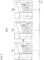
- Fig. 6 is a diagram showing an example of images 7A1-7A4 included in a moving image of a chapter.
- Fig. 7 is a diagram showing an example of images 7B1-7B3 included in a moving image of a chapter.
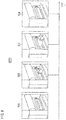
- Fig. 8 is a diagram showing an example of images 7C1-7C4 included in a moving image of a chapter.
- Fig. 9 is a diagram showing an example of images 7D1-7D3 included in a moving image of a chapter.
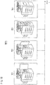
- Fig. 10 is a diagram showing an example of images 7E1-7E4 included in a moving image of a chapter.
- FIG. 11 is a diagram showing an example of images 7F1-7F3 included in a moving image of a chapter.
- Fig. 12 is a diagram showing an example of images 7G1-7G4 included in a moving image of a chapter.
- Fig. 13 is a diagram showing an example of images 7H1-7H3 included in a moving image of a chapter.
- Figs. 14A and 14B are diagrams showing examples of state data 6C.
- Fig. 15 is a diagram showing an example of a guidance screen 80.
- Fig. 16 is a flowchart depicting an example of the flow of jump destination time determination processing.
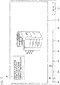
- Fig. 17 is a diagram showing an example of a message 7M.
- a user performs steps (processes, phases) according to a predetermined procedure, namely, in an orderly manner, so that the maintenance is performed completely.
- the state change data storage portion 101 stores, in advance, the state change data 6A for each type of maintenance.
- the state change data 6A shows, for each step, a change in state of the image forming apparatus 1 (state before the change thereof and state after the change thereof) for the case where the maintenance is performed in proper steps.
- the change in state is detected by any one of the sensors of the image forming apparatus 1.
- the state change data 6A for each type of maintenance may be described separately as “state change data 6A1", “state change data 6A2”, ..., and so on.
- the state change data 6A1 is the state change data 6A on maintenance to "clear a paper jam in the fixing unit".
- the state change data 6A1 shows, for each of five steps of the maintenance, a change in state for the case where the maintenance is performed properly and a sensor detecting the change in the following manner.
- the change to be detected at first is to "change the state of the right door 27 from the closed state to the open state".
- the right door sensor 204 detects the change.
- the change to be detected secondarily is to "change the state of the lever 24c from the "up” position to the “down” position".
- the lever sensor 205 detects the change.
- the change to be detected thirdly is to "change the state of the fixing unit 24 from paper present to no paper present".
- the first paper path sensor 201 detects the change.
- the change to be detected fourthly is to "change the state of the lever 24c from the "down” position to the "up” position".
- the lever sensor 205 detects the change.
- the change to be detected at last is to "change the state of the right door 27 from the open state to the closed state".
- the right door sensor 204 detects the change.
- the state change data 6A2 is the state change data 6A on maintenance to "clear a paper jam in the printed matter path".
- the state change data 6A2 shows, for each of five steps of the maintenance, a change in state for the case where the maintenance is performed properly and a sensor detecting the change in the following manner.
- the change to be detected at first is to "change the state of the right door 27 from the closed state to the open state" as with the case of clearing a paper jam in the fixing unit.
- the right door sensor 204 detects the change.
- the change to be detected secondarily is to "change the state of the inner door 28 from the closed state to the open state".
- the inner door sensor 206 detects the change.
- the change to be detected thirdly is to "change the state of the printed matter path 251 from paper present to no paper present".
- the second paper path sensor 202 detects the change.
- the change to be detected fourthly is to "change the state of the inner door 28 from the open state to the closed state".
- the inner door sensor 206 detects the change.
- the change to be detected at last is to "change the state of the right door 27 from the open state to the closed state" as with the case of clearing a paper jam in the fixing unit.
- the right door sensor 204 detects the change.
- the change in state of the image forming apparatus 1 is made in response to a task made by the user, namely, in response to user operation on the image forming apparatus 1. It can be therefore said that the state change data 6A also shows the user's task necessary to perform the maintenance.
- the state change data 6A also includes corresponding error 6AH.
- the state change data 6A1 includes, as the corresponding error 6AH, a corresponding error 6AH1.
- the "corresponding error” is an error to be corrected by performing maintenance related to the state change data 6A.
- the corresponding error 6AH1 is an error of "paper jam in the fixing unit” and an error to which maintenance to "clear a paper jam in the fixing unit” is to be performed.
- the reproduction data storage portion 102 stores, in advance, guidance data 6B for each piece of guidance. Stated differently, the reproduction data storage portion 102 stores, one by one, the guidance data 6B corresponding to the state change data 6A.
- the guidance data 6B corresponding to the state change data 6A1, the state change data 6A2, ..., and so on are sometimes described separately as “guidance data 6B1", “guidance data 6B2”, ..., and so on.
- the guidance data 6B is data on a moving image and audio for explaining how to perform maintenance.
- the guidance data 6B includes step data for each step.
- the guidance includes chapters for each step of the maintenance.
- the guidance data 6B corresponding to the state change data 6A1, namely, the guidance data 6B1 includes five sets of step data 6B11-6B15 (see Figs. 6-10 ).
- the step data 6B11-6B15 is data for reproducing moving images and audio of the fist through fifth chapters, respectively.
- the step data 6B11 is used to reproduce the moving image as shown in Fig. 6 .
- the moving image is so reproduced to show the transition from a state where the right door 27 is closed (image 7A1), to a state where the right door 27 is opened slightly (image 7A2), to a state where the right door 27 is opened by two thirds or so (image 7A3), and to a state where the right door 27 is opened completely (image 7A4).
- the images 7A1-7A4 form one frame of the moving image.
- the images 7B1-7B3, the images 7C1-7C4, the images 7D1-7D3, the images 7E1-7E4, the images 7F1-7F3, the images 7G1-7G4, and the images 7H1-7H3 form one frame each.
- the step data 6B 11 is used also to reproduce audio in line with the moving image. The same applies to the other step data described below.
- the step data 6B12 is used to reproduce the moving image as shown in Fig. 7 .
- the moving image is so reproduced to show the transition from a state where the right door 27 is opened completely and the lever 24c is in the "up” position (image 7B1), to a state where the lever 24c is in the "middle” position (image 7B2), and to a state where the heat rollers 24a and 24b are separated away from each other and the lever 24c is in the completely “down” position (image 7B3).
- the step data 6B13 is used to reproduce the moving image as shown in Fig. 8 .
- the moving image is so reproduced to show the transition from a state where the heat rollers 24a and 24b are separated away from each other and paper is jammed therebetween (image 7C1), to a state where the paper between the heat rollers 24a and 24b is pulled out slightly (image 7C2), to a state where the paper between the heat rollers 24a and 24b is pulled out fairly (image 7C3), and to a state where the paper is not jammed any more between the heat rollers 24a and 24b (image 7C4).
- the step data 6B 14 is used to reproduce the moving image as shown in Fig. 9 .
- the moving image is so reproduced to show the transition from a state where the heat rollers 24a and 24b are separated away from each other and the lever 24c is in the completely “down” position (image 7D1), to a state where the lever 24c is in the "middle” position (image 7D2), and to a state where the lever 24c is in the completely “up” position (image 7D3).
- the step data 6B15 is used to reproduce the moving image as shown in Fig. 10 .
- the moving image is so reproduced to show the transition from a state where the right door 27 is opened completely (image 7E1), to a state where the right door 27 is closed slightly (image 7E2), to a state where the right door 27 is closed by two thirds or so (image 7E3), and to a state where the right door 27 is closed completely (image 7E4).
- the guidance data 6B corresponding to the state change data 6A2, namely, the guidance data 6B2, includes five sets of step data 6B21-6B25.
- the step data 6B21 is used to reproduce a moving image and audio in a manner similar to that in the step data 6B 11 (see Fig. 6 ).
- the step data 6B22 is used to reproduce the moving image as shown in Fig. 11 .
- the moving image is so reproduced to show the transition from a state where the right door 27 is opened completely and the inner door 28 is closed (image 7F1), to a state where the inner door 28 is opened by half or so (image 7F2), and to a state where the inner door 28 is opened completely (image 7F3).
- the step data 6B23 is used to reproduce the moving image as shown in Fig. 12 .
- the moving image is so reproduced to show the transition from a state where paper is jammed in the printed matter path 251 (image 7G1), to a state where the paper is pulled out slightly (image 7G2), to a state where the paper is pulled out fairly (image 7G3), and to a state where the paper is removed from the printed matter path 251 (image 7G4).
- the step data 6B24 is used to reproduce the moving image as shown in Fig. 13 .
- the moving image is so reproduced to show the transition from a state where the inner door 28 is opened completely (image 7H1), to a state where the inner door 28 is opened by half or so (image 7H2), and to a state where the inner door 28 is closed completely (image 7H3).
- the step data 6B25 is used to reproduce a moving image and audio in a manner similar to that in the step data 6B15 (see Fig. 10 ).
- the step data for each step indicates a time (position, point) of the start (top) of the moving image of that step in the guidance.
- the moving images of the five steps of the guidance reproduced based on the guidance data 6B1 have lengths of "1 minute and 30 seconds", “45 seconds”, “1 minute and 5 seconds", “25 seconds”, and “35 seconds”, respectively.
- the step data 6B11-6B15 indicate, as the start time, a timestamp of "0 minute 0 second”, “1 minute 30 seconds”, “2 minutes 15 seconds”, “3 minutes 20 seconds”, and "3 minutes 45 seconds", respectively.
- the state data storage portion 103 stores state data 6C for each set of state change data 6A.
- the state data 6C for each set of state change data 6A1, state change data 6A2, ..., and so on is sometimes distinguished from one another as “state data 6C1", “state data 6C2”, ..., and so on.
- the state data 6C includes a complete flag 6D for each step of the maintenance.
- the complete flag 6D shows whether or not the step has been performed completely. If the complete flag 6D has a value of "1", then it means that the corresponding step has been performed completely. If the complete flag 6D has a value of "0”, then it means that the corresponding step has not yet been performed completely. All the complete flags 6D have an initial value of "0 (zero)".
- the state data 6C1 has complete flags 6D11-6D15 as the complete flags 6D for the five steps to clear a paper jam in the fixing unit.
- the state change detection portion 104 updates the complete flag 6D in accordance with the results of detection by the individual sensors. Which complete flag 6D is to be updated depending on which sensor detects what kind of change is defined in the state change data 6A.
- the state change detection portion 104 updates the complete flag 6D11 from “0" to “1” as shown in Fig. 14B . If the lever sensor 205 detects a change of the state of the lever 24c from the “up” position to the “down” position, then the state change detection portion 104 updates the complete flag 6D12 from “0" to "1” as shown in Fig. 14B .
- the guidance screen displaying portion 105 displays, in response to a predetermined command entered, the guidance screen 80 as shown in Fig. 15 in the touch-sensitive panel display 10e.
- the guidance screen 80 has a moving image window 81, a progress bar 82, a cursor 83, chapter buttons 84, a play button 85, and so on.
- a moving image of guidance to be reproduced (hereinafter, referred to as "target guidance") and the like are displayed.
- the target guidance is designated by the user.
- the guidance screen displaying portion 105 may select, as the target guidance, guidance on how to perform maintenance to clear an error occurred based on the state change data 6A (see Fig. 5 ). For example, if a paper jam error occurs in the fixing unit 24, then guidance on maintenance to "clear a paper jam in the fixing unit" is preferably selected as the target guidance.
- the progress bar 82 is to visualize how far the target guidance is played.
- the length L of the horizontal width of the progress bar 82 corresponds to the length of a time necessary to play the target guidance from the top to the end thereof at a normal speed (single speed). Such a time is hereinafter referred to as a "play duration T0".
- the left edge and the right edge of the progress bar 82 correspond to the top and the end of the target guidance, respectively.
- the progress bar 82 is sometimes called a "seekbar".
- the cursor 83 is provided on the progress bar 82.
- the cursor 83 moves in line with the time at which the target guidance is currently played.
- the time is hereinafter referred to as a "current play time Pg".
- the cursor 83 is also to visualize how far the target guidance is played.
- the play duration TO is "3 minutes and 30 seconds”
- the current play time Pg is "1 minute 10 seconds”.
- the cursor 83 is positioned on the right side, by L/3, from the left edge of the progress bar 82.
- the chapter buttons 84 are provided on the progress bar 82 so that one chapter button 84 corresponds to one chapter.
- the chapter buttons 84 are provided at the positions corresponding to the start times of the individual chapters.
- the progress bar 82 is displayed in a different format on the sides of the cursor 83.
- the progress bar 82 is displayed in red color on the left side of the cursor 83, and displayed in white color on the right side thereof.
- the different format on the sides of the cursor visualizes how far the target guidance is played.
- the cursor 83 indicates the progress of how far the target guidance is played by using the location of the cursor 83 in the progress bar 82.
- the default position of the cursor 83 is on the left edge of the progress bar 82.
- the user drags the cursor 83 to move the same to any position on the progress bar 82.
- the user taps any position on the progress bar 82 to move the cursor 83 to the tapped position.
- the user taps the chapter button 84 to move the cursor 83 to the position of the tapped chapter button 84. The user performs these operations to jump the playback progress to any point in time then to cause the target guidance to be played from the point in time.
- the cursor 83 sometimes moves to a position different from the position the user has dragged or tapped. This will be described later.
- the play button 85 is a button for the user to give a command to start playing the target guidance.
- the jump destination time determination portion 106 determines, in response to operation made on the progress bar 82, the cursor 83, or the chapter button 84, to which point in time of the target guidance the playback progress is to be jumped.
- the time corresponding to the jump destination is referred to as "jump destination time Ps”.
- the image forming apparatus 1 has two play modes: a normal mode; and the beginner mode.
- the two modes are different in a way of jumping the playback progress in response to the progress bar 82, the cursor 83, or the chapter button 84 operated.
- the user can arbitrarily select which of the play modes is to be used.
- the jump destination time determination portion 106 moves the cursor 83 just as the user drags or taps the cursor 83 as per the conventional manner. To be specific, the jump destination time determination portion 106 moves the cursor 83 to a position designated through the progress bar 82, the cursor 83, or the chapter button 84. The position designated is hereinafter referred to as a "designated position". The jump destination time determination portion 106 then determines that the jump destination time Ps is a time corresponding to the designated position.
- the jump destination time determination portion 106 determines that the jump destination time Ps is "0 minutes 35 seconds".
- the jump destination time determination portion 106 determines the jump destination time Ps according to the steps depicted in Fig. 16 .
- the jump destination time determination portion 106 retrieves the sets of state data 6C on the target guidance from the state data storage portion 103 (Step #701 of Fig. 16 ), and identifies a step of the time corresponding to the designated position (Step #702). The time can be identified based on the start time indicated in each set of step data of the guidance data 6B of the target guidance.
- the jump destination time determination portion 106 checks whether or not the step identified matches a step to be currently performed by the user (Step #703).
- the latter step is hereinafter referred to as a "particular step".
- the particular step can be determined based on the sets of state data 6C of the target guidance. To be specific, the complete flags 6D indicating "0" are searched from among the sets of state data 6C retrieved.
- the jump destination time determination portion 106 determines that a step related to a complete flag 6D which is closest to the top as compared with the other complete flags 6D indicating "0" is the particular step.
- the jump destination time determination portion 106 determines that the jump destination time Ps is time corresponding to the designated position as with the case of the normal mode (Step #705).
- the jump destination time determination portion 106 further moves the cursor 83 to the designated position.
- the jump destination time determination portion 106 may determine that the jump destination time Ps is time corresponding to the top of the step including the time corresponding to the designated position.
- the jump destination time determination portion 106 determines that the jump destination time Ps is time corresponding to the start (the first frame) of the particular step (Step #706). Stated differently, the jump destination time determination portion 106 determines that the jump destination time Ps is time corresponding to the start of the first step of the steps having not yet been performed completely. The determination is made irrespective of the time corresponding to the designated position.
- the jump destination time determination portion 106 determines that the jump destination time Ps is time corresponding to the start time of the third step, namely, "1 minute 30 seconds".
- the moving image reproducing portion 107 displays a moving image of target guidance in the moving image window 81 of the guidance screen 80 based on the guidance data 6B on the target guidance. In short, the moving image reproducing portion 107 reproduces the moving image of the target guidance.
- the moving image reproducing portion 107 reproduces the moving image as discussed below in accordance with operation by the user or the result of processing by the jump destination time determination portion 106.
- the moving image reproducing portion 107 When the user taps on the play button 85, the moving image reproducing portion 107 reads out the guidance data 6B on the target guidance from the reproduction data storage portion 102, and starts playing the target guidance from time corresponding to the current location of the cursor 83.
- the moving image reproducing portion 107 starts playing the target guidance from the top of the first step, namely, from "0 minute 0 second" because the default location of the cursor 83 is on the left edge of the progress bar 82.
- the jump destination time determination portion 106 determines jump destination time Ps as discussed above. In response to the determination, the moving image reproducing portion 107 jumps the playback progress to the jump destination time Ps and then continues to play the moving image from the jump destination time Ps.
- the moving image reproducing portion 107 skips the playback progress to the position of "3 minutes 25 seconds” and then plays the moving image from the position.
- the moving image reproducing portion 107 puts the playback progress back to the position of "2 minutes 15 seconds” and then plays the moving image from the position.
- the audio reproducing portion 108 controls, based on the guidance data 6B on the target guidance, the audio unit 10k in such a manner that audio is outputted in line with the display of the moving image by the moving image reproducing portion 107.
- the message displaying portion 109 displays the message 7M, as shown in Fig. 17 , in the moving image window 81.
- the message 7M says that as essential steps (processing) have not yet been performed, the playback progress is jumped to that incomplete section.
- the message displaying portion 109 may display the message 7M together with the moving image.
- the moving image reproducing portion 107 may reproduce the moving image.
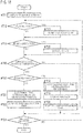
- Fig. 18 is a flowchart depicting an example of the flow of the entire processing for displaying guidance in the image forming apparatus 1.
- the description goes on to the flow of the processing for displaying guidance by the image forming apparatus 1.
- the image forming apparatus 1 performs the processing based on the guidance reproducing program 10P in accordance with the steps shown in Fig. 18 .
- the image forming apparatus 1 displays the guidance screen 80 (see Fig. 15 ) (Step #711).
- the image forming apparatus 1 reproduces the moving image and audio of the target guidance from time corresponding to the current location of the cursor 83 (Step #713).
- Step #714 If any one of the sensors detects a change in state (YES in Step #714), then the image forming apparatus 1 updates the value of any of the complete flags 6D (see Figs. 14A and 14B ) of the state data 6C of the target guidance with "1" in accordance with the change detected (Step #715).
- Step #716 If the progress bar 82, the cursor 83, or the chapter button 84 is operated (YES in Step #716) with the image forming apparatus 1 set at the beginner mode as the play mode (YES in Step #717), then the image forming apparatus 1 determines the jump destination time Ps in the manner as depicted in Fig 16 (Step #718).
- the image forming apparatus 1 displays the message 7M (see Fig. 17 ) (Step #719), and further jumps the playback progress to the jump destination time Ps (Step #720). At this time, the image forming apparatus 1 moves the cursor 83 to a position corresponding to the jump destination time Ps. If the target guidance is being played at this time, the image forming apparatus 1 skips the playback progress or puts it back to the jump destination time Ps and then continues to play the moving image from the jump destination time Ps.
- the image forming apparatus 1 moves the cursor 83 just as the user performs operation to determine the jump destination time Ps to be a position of the destination (designated position) (Step #721). Then, the image forming apparatus 1 jumps the playback progress to the jump destination time Ps (Step #722). If the target guidance is being played at this time (No in Step #723), then the image forming apparatus 1 skips the playback progress or puts it back to the jump destination time Ps and then continues to play the moving image from the jump destination time Ps.
- the image forming apparatus 1 appropriately performs the processing of Step #713, the processing of Step #715, the processing of Steps #718-#720, and the processing of Steps #721-#722 until a stop command is entered or until the moving image is played to the end.
- the guidance is reproduced, for example, in the following manner.
- the image forming apparatus 1 plays, as the target guidance, guidance to "clear a jam of a printed matter".
- the moving image of the guidance includes the images shown in Figs. 6 , 11 , 12 , 13 , and 10 .
- the user While the moving image is played, the user operates the progress bar 82, the cursor 83, or the chapter button 84, with the right door 27 opened and the inner door 28 not yet opened, to skip the playback progress or put it back to the step of removing the printed matter. In this state, however, the printed matter cannot be seen.
- the image forming apparatus 1 jumps the playback progress to the first step of the incomplete section, independently of the user operation, namely, to the top of a chapter of a step for opening the inner door 28 and then plays the moving image from the top of the chapter.
- the image forming apparatus 1 plays, as the target guidance, the guidance to "clear a paper jam in the fixing unit".
- the moving image of the guidance includes the images shown in Figs. 6-10 .
- the user While the moving image is played, the user operates the progress bar 82, the cursor 83, or the chapter button 84, with the right door 27 opened and the lever 24c not yet been moved down, to skip the playback progress or put it back to the step of removing the printed matter.
- the paper is probably torn. This makes it difficult to clear the error or leads to malfunction of the heat rollers 24a and 24b.
- the image forming apparatus 1 jumps the playback progress to the first step of the incomplete section, independently of the user operation, namely, to the top of a chapter of a step for moving the lever 24c down and then plays the moving image from the top of the chapter.
- the user can operate the image forming apparatus 1 to jump the playback progress to a position of a step (processing) which has not yet been performed and to play the guidance from the position of the step more easily than is conventionally possible.
- the moving image reproducing portion 107 and the audio reproducing portion 108 may change the speed for playing the guidance to be slower than the normal speed.
- the speed may be decreased to be approximately 0.5-0.9 times as fast as the normal speed.
- the moving image reproducing portion 107 and the audio reproducing portion 108 may play the chapter repeatedly until the step related to the chapter of the jump destination is performed completely.
- the audio reproducing portion 108 may prepare a flag indicating whether or not to output audio. In such a case, if the flag is ON, then the audio reproducing portion 108 controls the audio unit 10k to output audio. If the flag is OFF, then the audio reproducing portion 108 controls the audio unit 10k to output no audio. However, if jumping the playback progress to the top of the particular step of the guidance because the identified step and the particular step do not match each other, the audio reproducing portion 108 may output audio forcedly even if the flag is OFF.
- Fig. 19 is a diagram showing a modified example of the guidance screen 80.
- the chapter buttons 84 are provided on the progress bar 82.
- the chapter button may be provided in a different location from the progress bar 82. Such an example is shown as chapter buttons 86 of Fig. 19 .
- the user uses the progress bar 82, the cursor 83, or the chapter button 84 (see Fig. 15 ) to designate a jump destination of the target guidance.
- the user may use another method for such designation.
- the user may use numeric keys to enter time to be designated as the jump destination.
- the image forming apparatus 1 reproduces guidance.
- a terminal capable of performing communication with the image forming apparatus 1 for example, a smartphone or a tablet computer, may reproduce guidance.
- such a terminal preferably downloads, from the image forming apparatus 1, the data stored in the state change data storage portion 101, the reproduction data storage portion 102, or the state data storage portion 103.
- the terminal preferably receives, from the image forming apparatus 1, a result of detection by the sensors.
- the terminal is preferably provided with the state change detection portion 104, the guidance screen displaying portion 105, the jump destination time determination portion 106, the moving image reproducing portion 107, the audio reproducing portion 108, and the message displaying portion 109.
- a touch-sensitive panel display and an audio unit of the terminal are preferably used.
Landscapes
- Engineering & Computer Science (AREA)
- Multimedia (AREA)
- Signal Processing (AREA)
- Human Computer Interaction (AREA)
- General Engineering & Computer Science (AREA)
- Computing Systems (AREA)
- Physics & Mathematics (AREA)
- General Physics & Mathematics (AREA)
- Databases & Information Systems (AREA)
- Microelectronics & Electronic Packaging (AREA)
- Accessory Devices And Overall Control Thereof (AREA)
- Control Or Security For Electrophotography (AREA)
- Facsimiles In General (AREA)
- User Interface Of Digital Computer (AREA)
Abstract
Description
- Japanese Patent application No.
2016-201011 filed on October 12, 2016 - The present invention relates to a technology for reproducing maintenance guidance and so on.
- Recent years have seen the widespread use of image forming apparatuses into which functions such as copying, network printing, faxing, scanning, and file server are integrated. Such an image forming apparatus is called a "multifunction device" or a "Multi-Functional Peripheral (MFP)". Due to the different functions integrated, the image forming apparatus is complex in structure. This requires a user to perform a complicated task to deal with an error or a complicated task for maintenance.
- For the purpose of offering guidance on how to deal with such a complicated task to a user for easy understanding, the following technologies have been proposed, for example.
- One of the technologies is related to an image forming apparatus which includes: guide information display means for displaying operation guide information stored in operation guide information storage means; equipment state information creation means for acquiring sensor information from sensors arranged at respective places to create equipment state information for specifying the equipment state of the apparatus; state screen specification table on which the equipment state information and the operation guide information displayed in the respective equipment states are associated with each other; and screen information determination means for comparing the equipment state information created by the equipment state information creation means with the equipment state information registered to the state screen specification table to determine the operation guide information to be displayed on the guide information display means. When the equipment state information creation means updates the equipment state information, the screen information determination means switches the operation guide information to be displayed in real time on the guide information display means (English abstract of Japanese Laid-open Patent Publication No.
2014-203001 - The other is related to an image processing apparatus capable of reproducing a video. The image processing apparatus includes a moving means for moving the reproduction position of a video to an arbitrary position according to the user operation, and determines whether the reproduction position after movement is a position rewound from the reproduction position before movement. If a determination is made that the reproduction position after movement is a position rewound from the reproduction position before movement, the image processing apparatus is provided with an operation means for designating control of loop reproduction of a section from the start position to the end position by saving the reproduction position after movement as the start position of a section subjected to loop reproduction, and saving the reproduction position before movement as the end position of a section subjected to loop reproduction (English abstract of Japanese Laid-open Patent Publication No.
2013-135404 - In some cases, a user cannot perform a task as shown in guidance even while he/she watches a moving image for the guidance to perform the task. In such a case, the user sometimes skips a part of the task to move to the next task.
- This, however, causes a device failure in some cases. For example, in an image forming apparatus, when a pair of rollers to feed paper or to fix toner onto paper are used, the rollers are pressed onto each other. However, the rollers are separated from each other in order to fix a paper jam.
- When a user tries to pull out the jammed paper with the pair of rollers pressed onto each other, the jammed paper is sometimes torn, which makes it difficult to remove the paper, or, the rollers sometimes go out of order unintentionally.
- In light of this, it is desirable for the user to jump a playback progress to a position corresponding to the part of the task having not yet been finished and then to watch the guidance. As a method for designating a jump destination, tapping on a progress bar, moving a cursor on the progress bar, or any other methods are known.
- However, it is difficult to designate a desired jump destination with the use of the progress bar or the cursor.
- The present invention has been achieved in light of such a problem, and therefore, an object of an embodiment of the present invention is to enable a user to jump a playback progress to a position corresponding to a part of a task having not yet been finished more easily than is conventionally possible.
- To achieve at least one of the abovementioned objects, according to an aspect of the present invention, a device reflecting one aspect of the present invention is a device for reproducing guidance on a task including a plurality of steps. The device includes an input device with which a user selects from which position of the guidance is to be reproduced; and a player configured to where a designated step corresponding to the position selected by the user from among the steps is a particular step, jump a playback progress to the position selected to play the guidance, the particular step being an initial step of steps having not yet been performed completely, and where the designated step is not the particular step, jump the playback progress to a position of the particular step to play the guidance.
- The advantages and features provided by one or more embodiments of the invention will become more fully understood from the detailed description given hereinbelow and the appended drawings which are given by way of illustration only, and thus are not intended as a definition of the limits of the present invention.
-
Fig. 1 is a diagram showing an example of the external view of an image forming apparatus. -
Fig. 2 is a diagram showing an example of the configuration of a printing unit of an image forming apparatus. -
Fig. 3 is a diagram showing an example of the hardware configuration of an image forming apparatus. -
Fig. 4 is a diagram showing an example of the functional configuration of an image forming apparatus. -
Fig. 5 is a diagram showing an example of state change data. -
Fig. 6 is a diagram showing an example of images included in a moving image of a chapter. -
Fig. 7 is a diagram showing an example of images included in a moving image of a chapter. -
Fig. 8 is a diagram showing an example of images included in a moving image of a chapter. -
Fig. 9 is a diagram showing an example of images included in a moving image of a chapter. -
Fig. 10 is a diagram showing an example of images included in a moving image of a chapter. -
Fig. 11 is a diagram showing an example of images included in a moving image of a chapter. -
Fig. 12 is a diagram showing an example of images included in a moving image of a chapter. -
Fig. 13 is a diagram showing an example of images included in a moving image of a chapter. -
Figs. 14A and14B are diagrams showing examples of state data. -
Fig. 15 is a diagram showing an example of a guidance screen. -
Fig. 16 is a flowchart depicting an example of the flow of jump destination time determination processing. -
Fig. 17 is a diagram showing an example of a message. -
Fig. 18 is a flowchart depicting an example of the flow of the entire processing for displaying guidance in an image forming apparatus. -
Fig. 19 is a diagram showing a modified example of a guidance screen. - Hereinafter, one or more embodiments of the present invention will be described with reference to the drawings. However, the scope of the invention is not limited to the disclosed embodiments.
-
Fig. 1 is a diagram showing an example of the external view of animage forming apparatus 1. -
Fig. 2 is a diagram showing an example of the configuration of aprinting unit 10i of theimage forming apparatus 1.Fig. 3 is a diagram showing an example of the hardware configuration of theimage forming apparatus 1.Fig. 4 is a diagram showing an example of the functional configuration of theimage forming apparatus 1. - The
image forming apparatus 1 shown inFig. 1 is an apparatus into which functions such as copying, PC printing, cloud printing, faxing, scanning, and box function are incorporated. Theimage forming apparatus 1 is generally called a "multifunction device" or a "Multi-Functional Peripheral (MFP)". Theimage forming apparatus 1 is provided in a Local Area Network (LAN). - The PC printing function is to print an image onto paper based on image data received from a terminal provided in the LAN. The PC printing function is sometimes called a "network printing function" or "network printer function".
- The cloud printing function is to receive image data from a terminal external to the
image forming apparatus 1 through a server on the Internet to print an image onto paper. - According to the box function, each user is given a storage area called a "box" or a "personal box". The box function enables each user to save image data and so on to his/her storage area and to manage the image data and so on therein. Such boxes may be provided on a group-by-group basis and be shared by group members. The box corresponds to a "folder" or a "directory" in a personal computer.
- Referring to
Figs. 1-3 , theimage forming apparatus 1 is configured of acontrol unit 11, a touch-sensitive panel display 10e, an operatingkey panel 10f, a Network Interface Card (NIC) 10g, ascanner unit 10h, theprinting unit 10i, afinisher 10j, anaudio unit 10k, and so on. - The touch-
sensitive panel display 10e displays, for example, a screen for presenting messages to the user, a screen for allowing the user to input commands or information, a screen for showing the results of processing executed by thecontrol unit 11. The touch-sensitive panel display 10e also displays a moving image of guidance on how to operate theimage forming apparatus 1. The touch-sensitive panel display 10e sends a signal indicating a touched location to thecontrol unit 11. - The operating
key panel 10f is a so-called hardware keyboard. The operatingkey panel 10f has numeric keys, a start key, a stop key, and a function key. - The
NIC 10g performs communication with other device in accordance with a protocol such as Transmission Control Protocol/Internet Protocol (TCP/IP). - The
scanner unit 10h optically reads an image on a sheet of paper placed on a platen glass to generate image data thereof. - The
printing unit 10i includes animage formation section 21, apaper feed section 22, apaper feed cabinet 23, a fixingunit 24, a printedmatter path 251, afeedback path 252, an upperfront door 26, aright door 27, aninner door 28, a firstpaper path sensor 201, a secondpaper path sensor 202, an upperfront door sensor 203, aright door sensor 204, alever sensor 205, and aninner door sensor 206. The configuration enables printing, onto paper, of an image read out by thescanner unit 10h and of an image received by theNIC 10g from other terminal. - The
image formation section 21 is a tandem color print engine or a color print engine by electrophotographic steps. Theimage formation section 21 is provided withphotoconductive drums exposure scanning units transfer belt 33, and so on. - The
photoconductive drums exposure scanning units - The
exposure scanning units control unit 11 to form latent images on thephotoconductive drums - The toner images of the individual colors formed on the
photoconductive drums transfer belt 33. Thereby, a full-color toner image is formed on thetransfer belt 33. - The
paper feed section 22 is included as standard equipment in theimage forming apparatus 1. Thepaper feed section 22 is a unit for supplying paper to theimage formation section 21. Thepaper feed section 22 is provided with one or morepaper feed cassettes 22a,pickup rollers 22b, and so on. Paper sheets are loaded into thepaper feed cassettes 22a. Thepickup rollers 22b pick up the paper sheets, one by one, from thepaper feed cassettes 22a to send out the paper sheet to theimage formation section 21. - As with the
paper feed section 22, thepaper feed cabinet 23 is a unit for supplying paper to theimage formation section 21. Thepaper feed cabinet 23 is mounted on theimage forming apparatus 1 as optional equipment. The paper sent out, bypickup rollers 23b, from thepaper feed cassettes 23a of thepaper feed cabinet 23 is fed through thepaper feed section 22 to theimage formation section 21. - The fixing
unit 24 is provided with twoheat rollers lever 24c, and so on. The toner image formed on thetransfer belt 33 is transferred by theheat rollers paper feed section 22 or thepaper feed cabinet 23. Moving thelever 24c down separates theheat rollers lever 24c up presses theheat rollers - The printed
matter path 251 is a path for a printed matter having the toner image transferred by the fixingunit 24 to be conveyed to thefinisher 10j. - The upper
front door 26 is provided in the front face of theimage forming apparatus 1. A job such as printing is executed with the upperfront door 26 closed. Maintenance such as a task for clearing an error or adding consumables is performed with the upperfront door 26 opened appropriately. - The
right door 27 is provided on the observer's right of theimage forming apparatus 1. Theinner door 28 is to cover the printedmatter path 251 and thefeedback path 252. A job such as printing is executed with theright door 27 and theinner door 28 closed. The maintenance is performed with theright door 27 or theinner door 28 opened appropriately. - The first
paper path sensor 201 is disposed near the fixingunit 24 to detect the presence/absence of paper at this position. The firstpaper path sensor 201 also detects a paper jam occurring in the fixingunit 24. - The second
paper path sensor 202 is disposed near the printed matter path 25 to detect the presence/absence of a printed matter at this position. - The upper
front door sensor 203 is disposed near the upperfront door 26 to detect an open/closed state of the upperfront door 26. Theright door sensor 204 is disposed near theright door 27 to detect an open/closed state of theright door 27. - The
lever sensor 205 detects a state of thelever 24c, specifically, detects whether thelever 24c is in the "up" position or the "down" position. Theinner door sensor 206 is disposed near theinner door 28 to detect an open/closed state of theinner door 28. - The
finisher 10j applies a post-process, if necessary, to the printed matter obtained by theprinting unit 10i. The post-process includes stapling the printed matter, punching a hole in the printed matter, and folding the printed matter. - For double-sided printing, paper having an image printed on its one side is switched back near the
finisher 10j, and then is fed again to theimage formation section 21. - The
audio unit 10k is configured of a soundboard, a speaker, and so on to output audio guidance. - The
control unit 11 is configured of a Central Processing Unit (CPU) 10a, a Random Access Memory (RAM) 10b, a Read Only Memory (ROM) 10c, anauxiliary storage 10d, and so on. - The
ROM 10c or theauxiliary storage 10d stores, therein, a program for implementing the foregoing functions such as copying function. TheROM 10c or theauxiliary storage 10d also stores, therein, aguidance reproducing program 10P (Fig. 4 ). - The
guidance reproducing program 10P is to reproduce a moving image and audio of guidance which gives the user an explanation for maintenance how to clear an error or to add consumables. - The programs are loaded into the
RAM 10b as necessary, and are executed by theCPU 10a. Theauxiliary storage 10d is, for example, a hard disk drive or a Solid State Drive (SSD). - The
guidance reproducing program 10P implements the functions of a state changedata storage portion 101, a reproductiondata storage portion 102, a statedata storage portion 103, a statechange detection portion 104, a guidancescreen displaying portion 105, a jump destinationtime determination portion 106, a movingimage reproducing portion 107, anaudio reproducing portion 108, amessage displaying portion 109, and so on, all of which are shown inFig. 4 . - Hereinafter, the individual portions of the state change
data storage portion 101 through themessage displaying portion 109 are described. -
Fig. 5 is a diagram showing an example ofstate change data 6A.Fig. 6 is a diagram showing an example of images 7A1-7A4 included in a moving image of a chapter.Fig. 7 is a diagram showing an example of images 7B1-7B3 included in a moving image of a chapter.Fig. 8 is a diagram showing an example of images 7C1-7C4 included in a moving image of a chapter.Fig. 9 is a diagram showing an example of images 7D1-7D3 included in a moving image of a chapter.Fig. 10 is a diagram showing an example of images 7E1-7E4 included in a moving image of a chapter.Fig. 11 is a diagram showing an example of images 7F1-7F3 included in a moving image of a chapter.Fig. 12 is a diagram showing an example of images 7G1-7G4 included in a moving image of a chapter.Fig. 13 is a diagram showing an example of images 7H1-7H3 included in a moving image of a chapter.Figs. 14A and14B are diagrams showing examples ofstate data 6C.Fig. 15 is a diagram showing an example of aguidance screen 80.Fig. 16 is a flowchart depicting an example of the flow of jump destination time determination processing.Fig. 17 is a diagram showing an example of amessage 7M. - Meanwhile, in general, a user performs steps (processes, phases) according to a predetermined procedure, namely, in an orderly manner, so that the maintenance is performed completely.
- In this embodiment, it is confirmed, based on the result of detection by any one of the sensors of the
image forming apparatus 1, that one step is performed properly. - Referring to
Fig. 5 , the state changedata storage portion 101 stores, in advance, thestate change data 6A for each type of maintenance. - The
state change data 6A shows, for each step, a change in state of the image forming apparatus 1 (state before the change thereof and state after the change thereof) for the case where the maintenance is performed in proper steps. The change in state is detected by any one of the sensors of theimage forming apparatus 1. Hereinafter, thestate change data 6A for each type of maintenance may be described separately as "state change data 6A1", "state change data 6A2", ..., and so on. - For example, the state change data 6A1 is the
state change data 6A on maintenance to "clear a paper jam in the fixing unit". - The state change data 6A1 shows, for each of five steps of the maintenance, a change in state for the case where the maintenance is performed properly and a sensor detecting the change in the following manner.
- The change to be detected at first is to "change the state of the
right door 27 from the closed state to the open state". Theright door sensor 204 detects the change. - The change to be detected secondarily is to "change the state of the
lever 24c from the "up" position to the "down" position". Thelever sensor 205 detects the change. - The change to be detected thirdly is to "change the state of the fixing
unit 24 from paper present to no paper present". The firstpaper path sensor 201 detects the change. - The change to be detected fourthly is to "change the state of the
lever 24c from the "down" position to the "up" position". Thelever sensor 205 detects the change. - The change to be detected at last is to "change the state of the
right door 27 from the open state to the closed state". Theright door sensor 204 detects the change. - The state change data 6A2 is the
state change data 6A on maintenance to "clear a paper jam in the printed matter path". - The state change data 6A2 shows, for each of five steps of the maintenance, a change in state for the case where the maintenance is performed properly and a sensor detecting the change in the following manner.
- The change to be detected at first is to "change the state of the
right door 27 from the closed state to the open state" as with the case of clearing a paper jam in the fixing unit. Theright door sensor 204 detects the change. - The change to be detected secondarily is to "change the state of the
inner door 28 from the closed state to the open state". Theinner door sensor 206 detects the change. - The change to be detected thirdly is to "change the state of the printed
matter path 251 from paper present to no paper present". The secondpaper path sensor 202 detects the change. - The change to be detected fourthly is to "change the state of the
inner door 28 from the open state to the closed state". Theinner door sensor 206 detects the change. - The change to be detected at last is to "change the state of the
right door 27 from the open state to the closed state" as with the case of clearing a paper jam in the fixing unit. Theright door sensor 204 detects the change. - The change in state of the
image forming apparatus 1 is made in response to a task made by the user, namely, in response to user operation on theimage forming apparatus 1. It can be therefore said that thestate change data 6A also shows the user's task necessary to perform the maintenance. - The
state change data 6A also includes corresponding error 6AH. For example, the state change data 6A1 includes, as the corresponding error 6AH, a corresponding error 6AH1. The "corresponding error" is an error to be corrected by performing maintenance related to thestate change data 6A. To be specific, for example, the corresponding error 6AH1 is an error of "paper jam in the fixing unit" and an error to which maintenance to "clear a paper jam in the fixing unit" is to be performed. - The reproduction
data storage portion 102 stores, in advance,guidance data 6B for each piece of guidance. Stated differently, the reproductiondata storage portion 102 stores, one by one, theguidance data 6B corresponding to thestate change data 6A. Hereinafter, theguidance data 6B corresponding to the state change data 6A1, the state change data 6A2, ..., and so on are sometimes described separately as "guidance data 6B1", "guidance data 6B2", ..., and so on. - The
guidance data 6B is data on a moving image and audio for explaining how to perform maintenance. Theguidance data 6B includes step data for each step. The guidance includes chapters for each step of the maintenance. - For example, the
guidance data 6B corresponding to the state change data 6A1, namely, the guidance data 6B1, includes five sets of step data 6B11-6B15 (seeFigs. 6-10 ). The step data 6B11-6B15 is data for reproducing moving images and audio of the fist through fifth chapters, respectively. - The step data 6B11 is used to reproduce the moving image as shown in
Fig. 6 . To be specific, the moving image is so reproduced to show the transition from a state where theright door 27 is closed (image 7A1), to a state where theright door 27 is opened slightly (image 7A2), to a state where theright door 27 is opened by two thirds or so (image 7A3), and to a state where theright door 27 is opened completely (image 7A4). - The images 7A1-7A4 form one frame of the moving image. Likewise, the images 7B1-7B3, the images 7C1-7C4, the images 7D1-7D3, the images 7E1-7E4, the images 7F1-7F3, the images 7G1-7G4, and the images 7H1-7H3 form one frame each.
- The
step data 6B - The step data 6B12 is used to reproduce the moving image as shown in
Fig. 7 . To be specific, the moving image is so reproduced to show the transition from a state where theright door 27 is opened completely and thelever 24c is in the "up" position (image 7B1), to a state where thelever 24c is in the "middle" position (image 7B2), and to a state where theheat rollers lever 24c is in the completely "down" position (image 7B3). - The step data 6B13 is used to reproduce the moving image as shown in
Fig. 8 . To be specific, the moving image is so reproduced to show the transition from a state where theheat rollers heat rollers heat rollers heat rollers - The
step data 6B 14 is used to reproduce the moving image as shown inFig. 9 . To be specific, the moving image is so reproduced to show the transition from a state where theheat rollers lever 24c is in the completely "down" position (image 7D1), to a state where thelever 24c is in the "middle" position (image 7D2), and to a state where thelever 24c is in the completely "up" position (image 7D3). - The step data 6B15 is used to reproduce the moving image as shown in
Fig. 10 . To be specific, the moving image is so reproduced to show the transition from a state where theright door 27 is opened completely (image 7E1), to a state where theright door 27 is closed slightly (image 7E2), to a state where theright door 27 is closed by two thirds or so (image 7E3), and to a state where theright door 27 is closed completely (image 7E4). - The
guidance data 6B corresponding to the state change data 6A2, namely, the guidance data 6B2, includes five sets of step data 6B21-6B25. - The step data 6B21 is used to reproduce a moving image and audio in a manner similar to that in the
step data 6B 11 (seeFig. 6 ). - The step data 6B22 is used to reproduce the moving image as shown in
Fig. 11 . To be specific, the moving image is so reproduced to show the transition from a state where theright door 27 is opened completely and theinner door 28 is closed (image 7F1), to a state where theinner door 28 is opened by half or so (image 7F2), and to a state where theinner door 28 is opened completely (image 7F3). - The step data 6B23 is used to reproduce the moving image as shown in
Fig. 12 . To be specific, the moving image is so reproduced to show the transition from a state where paper is jammed in the printed matter path 251 (image 7G1), to a state where the paper is pulled out slightly (image 7G2), to a state where the paper is pulled out fairly (image 7G3), and to a state where the paper is removed from the printed matter path 251 (image 7G4). - The step data 6B24 is used to reproduce the moving image as shown in
Fig. 13 . To be specific, the moving image is so reproduced to show the transition from a state where theinner door 28 is opened completely (image 7H1), to a state where theinner door 28 is opened by half or so (image 7H2), and to a state where theinner door 28 is closed completely (image 7H3). - The step data 6B25 is used to reproduce a moving image and audio in a manner similar to that in the step data 6B15 (see
Fig. 10 ). - In addition, the step data for each step indicates a time (position, point) of the start (top) of the moving image of that step in the guidance. Suppose, for example, that the moving images of the five steps of the guidance reproduced based on the guidance data 6B1 have lengths of "1 minute and 30 seconds", "45 seconds", "1 minute and 5 seconds", "25 seconds", and "35 seconds", respectively. In such a case, the step data 6B11-6B15 indicate, as the start time, a timestamp of "0
minute 0 second", "1 minute 30 seconds", "2 minutes 15 seconds", "3 minutes 20 seconds", and "3 minutes 45 seconds", respectively. - Referring to
Fig. 14A , the statedata storage portion 103stores state data 6C for each set ofstate change data 6A. Hereinafter, thestate data 6C for each set of state change data 6A1, state change data 6A2, ..., and so on is sometimes distinguished from one another as "state data 6C1", "state data 6C2", ..., and so on. - The
state data 6C includes acomplete flag 6D for each step of the maintenance. Thecomplete flag 6D shows whether or not the step has been performed completely. If thecomplete flag 6D has a value of "1", then it means that the corresponding step has been performed completely. If thecomplete flag 6D has a value of "0", then it means that the corresponding step has not yet been performed completely. All thecomplete flags 6D have an initial value of "0 (zero)". - For example, the state data 6C1 has complete flags 6D11-6D15 as the
complete flags 6D for the five steps to clear a paper jam in the fixing unit. - The state
change detection portion 104 updates thecomplete flag 6D in accordance with the results of detection by the individual sensors. Whichcomplete flag 6D is to be updated depending on which sensor detects what kind of change is defined in thestate change data 6A. - For example, if the
right door sensor 204 detects a change of the state of theright door 27 from the closed state to the open state, then the statechange detection portion 104 updates the complete flag 6D11 from "0" to "1" as shown inFig. 14B . If thelever sensor 205 detects a change of the state of thelever 24c from the "up" position to the "down" position, then the statechange detection portion 104 updates the complete flag 6D12 from "0" to "1" as shown inFig. 14B . - The guidance
screen displaying portion 105 displays, in response to a predetermined command entered, theguidance screen 80 as shown inFig. 15 in the touch-sensitive panel display 10e. - The
guidance screen 80 has a movingimage window 81, aprogress bar 82, acursor 83,chapter buttons 84, aplay button 85, and so on. - In the moving
image window 81, a moving image of guidance to be reproduced (hereinafter, referred to as "target guidance") and the like are displayed. The target guidance is designated by the user. Alternatively, the guidancescreen displaying portion 105 may select, as the target guidance, guidance on how to perform maintenance to clear an error occurred based on thestate change data 6A (seeFig. 5 ). For example, if a paper jam error occurs in the fixingunit 24, then guidance on maintenance to "clear a paper jam in the fixing unit" is preferably selected as the target guidance. - The
progress bar 82 is to visualize how far the target guidance is played. The length L of the horizontal width of theprogress bar 82 corresponds to the length of a time necessary to play the target guidance from the top to the end thereof at a normal speed (single speed). Such a time is hereinafter referred to as a "play duration T0". The left edge and the right edge of theprogress bar 82 correspond to the top and the end of the target guidance, respectively. Theprogress bar 82 is sometimes called a "seekbar". - The
cursor 83 is provided on theprogress bar 82. Thecursor 83 moves in line with the time at which the target guidance is currently played. The time is hereinafter referred to as a "current play time Pg". Thecursor 83 is also to visualize how far the target guidance is played. Suppose, for example, that the play duration TO is "3 minutes and 30 seconds" and the current play time Pg is "1 minute 10 seconds". In such a case, thecursor 83 is positioned on the right side, by L/3, from the left edge of theprogress bar 82. - The
chapter buttons 84 are provided on theprogress bar 82 so that onechapter button 84 corresponds to one chapter. Thechapter buttons 84 are provided at the positions corresponding to the start times of the individual chapters. - The
progress bar 82 is displayed in a different format on the sides of thecursor 83. For example, theprogress bar 82 is displayed in red color on the left side of thecursor 83, and displayed in white color on the right side thereof. Stated differently, the different format on the sides of the cursor visualizes how far the target guidance is played. As described above, thecursor 83 indicates the progress of how far the target guidance is played by using the location of thecursor 83 in theprogress bar 82. The default position of thecursor 83 is on the left edge of theprogress bar 82. - The user drags the
cursor 83 to move the same to any position on theprogress bar 82. Alternatively, the user taps any position on theprogress bar 82 to move thecursor 83 to the tapped position. Alternatively, the user taps thechapter button 84 to move thecursor 83 to the position of the tappedchapter button 84. The user performs these operations to jump the playback progress to any point in time then to cause the target guidance to be played from the point in time. - However, where a beginner mode is set as the play mode, the
cursor 83 sometimes moves to a position different from the position the user has dragged or tapped. This will be described later. - The
play button 85 is a button for the user to give a command to start playing the target guidance. - The jump destination
time determination portion 106 determines, in response to operation made on theprogress bar 82, thecursor 83, or thechapter button 84, to which point in time of the target guidance the playback progress is to be jumped. Hereinafter, the time corresponding to the jump destination is referred to as "jump destination time Ps". - In the meantime, the
image forming apparatus 1 has two play modes: a normal mode; and the beginner mode. The two modes are different in a way of jumping the playback progress in response to theprogress bar 82, thecursor 83, or thechapter button 84 operated. The user can arbitrarily select which of the play modes is to be used. - In the normal mode, the jump destination
time determination portion 106 moves thecursor 83 just as the user drags or taps thecursor 83 as per the conventional manner. To be specific, the jump destinationtime determination portion 106 moves thecursor 83 to a position designated through theprogress bar 82, thecursor 83, or thechapter button 84. The position designated is hereinafter referred to as a "designated position". The jump destinationtime determination portion 106 then determines that the jump destination time Ps is a time corresponding to the designated position. - Suppose, for example, that the play duration TO is "3 minutes and 30 seconds" and the designated position is a position which is L/6 rightward away from the left edge of the
progress bar 82. In such a case, the jump destinationtime determination portion 106 determines that the jump destination time Ps is "0 minutes 35 seconds". - In contrast, in the beginner mode, the jump destination
time determination portion 106 determines the jump destination time Ps according to the steps depicted inFig. 16 . - The jump destination
time determination portion 106 retrieves the sets ofstate data 6C on the target guidance from the state data storage portion 103 (Step # 701 ofFig. 16 ), and identifies a step of the time corresponding to the designated position (Step #702). The time can be identified based on the start time indicated in each set of step data of theguidance data 6B of the target guidance. - The jump destination
time determination portion 106 checks whether or not the step identified matches a step to be currently performed by the user (Step #703). The latter step is hereinafter referred to as a "particular step". The particular step can be determined based on the sets ofstate data 6C of the target guidance. To be specific, thecomplete flags 6D indicating "0" are searched from among the sets ofstate data 6C retrieved. The jump destinationtime determination portion 106 determines that a step related to acomplete flag 6D which is closest to the top as compared with the othercomplete flags 6D indicating "0" is the particular step. - If the identified step matches the particular step (YES in Step #704), then the jump destination
time determination portion 106 determines that the jump destination time Ps is time corresponding to the designated position as with the case of the normal mode (Step #705). The jump destinationtime determination portion 106 further moves thecursor 83 to the designated position. The jump destinationtime determination portion 106 may determine that the jump destination time Ps is time corresponding to the top of the step including the time corresponding to the designated position. - On the other hand, unless the identified step matches the particular step (NO in Step #704), then the jump destination
time determination portion 106 determines that the jump destination time Ps is time corresponding to the start (the first frame) of the particular step (Step #706). Stated differently, the jump destinationtime determination portion 106 determines that the jump destination time Ps is time corresponding to the start of the first step of the steps having not yet been performed completely. The determination is made irrespective of the time corresponding to the designated position. - Suppose, for example, that the target guidance is guidance to clear a paper jam in the fixing unit, and that the
complete flags 6D of thestate data 6C on the maintenance indicate the values as shown inFig. 14B . In such a case, the jump destinationtime determination portion 106 determines that the jump destination time Ps is time corresponding to the start time of the third step, namely, "1 minute 30 seconds". - Referring back to
Fig. 4 , the movingimage reproducing portion 107 displays a moving image of target guidance in the movingimage window 81 of theguidance screen 80 based on theguidance data 6B on the target guidance. In short, the movingimage reproducing portion 107 reproduces the moving image of the target guidance. - To be specific, the moving
image reproducing portion 107 reproduces the moving image as discussed below in accordance with operation by the user or the result of processing by the jump destinationtime determination portion 106. - When the user taps on the
play button 85, the movingimage reproducing portion 107 reads out theguidance data 6B on the target guidance from the reproductiondata storage portion 102, and starts playing the target guidance from time corresponding to the current location of thecursor 83. When the user has not yet operated theprogress bar 82 or thecursor 83, the movingimage reproducing portion 107 starts playing the target guidance from the top of the first step, namely, from "0minute 0 second" because the default location of thecursor 83 is on the left edge of theprogress bar 82. - When the user operates the
progress bar 82 or thecursor 83 with the target guidance played, the jump destinationtime determination portion 106 determines jump destination time Ps as discussed above. In response to the determination, the movingimage reproducing portion 107 jumps the playback progress to the jump destination time Ps and then continues to play the moving image from the jump destination time Ps. - Suppose, for example, that the jump destination time Ps is determined to be "3 minutes 25 seconds" while the moving image corresponding to the time "3
minutes 5 seconds" is played. In such a case, the movingimage reproducing portion 107 skips the playback progress to the position of "3 minutes 25 seconds" and then plays the moving image from the position. In another example, if the jump destination time Ps is determined to be "2 minutes 15 seconds" while the moving image corresponding to the time "3minutes 5 seconds" is played, then the movingimage reproducing portion 107 puts the playback progress back to the position of "2 minutes 15 seconds" and then plays the moving image from the position. - The
audio reproducing portion 108 controls, based on theguidance data 6B on the target guidance, theaudio unit 10k in such a manner that audio is outputted in line with the display of the moving image by the movingimage reproducing portion 107. - If the jump destination time Ps is determined to be time different from the time corresponding to the designated position, then the
message displaying portion 109 displays themessage 7M, as shown inFig. 17 , in the movingimage window 81. Themessage 7M says that as essential steps (processing) have not yet been performed, the playback progress is jumped to that incomplete section. - The
message displaying portion 109 may display themessage 7M together with the moving image. Alternatively, when a predetermined amount of time has elapsed or the user performs predetermined operation after themessage 7M was displayed, the movingimage reproducing portion 107 may reproduce the moving image. -
Fig. 18 is a flowchart depicting an example of the flow of the entire processing for displaying guidance in theimage forming apparatus 1. - The description goes on to the flow of the processing for displaying guidance by the
image forming apparatus 1. - The
image forming apparatus 1 performs the processing based on theguidance reproducing program 10P in accordance with the steps shown inFig. 18 . - The
image forming apparatus 1 displays the guidance screen 80 (seeFig. 15 ) (Step #711). In response to theplay button 85 tapped (YES in Step #712), theimage forming apparatus 1 reproduces the moving image and audio of the target guidance from time corresponding to the current location of the cursor 83 (Step #713). - If any one of the sensors detects a change in state (YES in Step #714), then the
image forming apparatus 1 updates the value of any of thecomplete flags 6D (seeFigs. 14A and14B ) of thestate data 6C of the target guidance with "1" in accordance with the change detected (Step #715). - If the
progress bar 82, thecursor 83, or thechapter button 84 is operated (YES in Step #716) with theimage forming apparatus 1 set at the beginner mode as the play mode (YES in Step #717), then theimage forming apparatus 1 determines the jump destination time Ps in the manner as depicted inFig 16 (Step #718). Theimage forming apparatus 1 displays themessage 7M (seeFig. 17 ) (Step #719), and further jumps the playback progress to the jump destination time Ps (Step #720). At this time, theimage forming apparatus 1 moves thecursor 83 to a position corresponding to the jump destination time Ps. If the target guidance is being played at this time, theimage forming apparatus 1 skips the playback progress or puts it back to the jump destination time Ps and then continues to play the moving image from the jump destination time Ps. - On the other hand, if the normal mode is set as the play mode (No in Step #717), then the
image forming apparatus 1 moves thecursor 83 just as the user performs operation to determine the jump destination time Ps to be a position of the destination (designated position) (Step #721). Then, theimage forming apparatus 1 jumps the playback progress to the jump destination time Ps (Step #722). If the target guidance is being played at this time (No in Step #723), then theimage forming apparatus 1 skips the playback progress or puts it back to the jump destination time Ps and then continues to play the moving image from the jump destination time Ps. - The
image forming apparatus 1 appropriately performs the processing ofStep # 713, the processing ofStep # 715, the processing of Steps #718-#720, and the processing of Steps #721-#722 until a stop command is entered or until the moving image is played to the end. - According to the foregoing processing, when the beginner mode is set, the guidance is reproduced, for example, in the following manner.
- When a printed matter is jammed in the printed
matter path 251, theimage forming apparatus 1 plays, as the target guidance, guidance to "clear a jam of a printed matter". The moving image of the guidance includes the images shown inFigs. 6 ,11 ,12 ,13 , and10 . - While the moving image is played, the user operates the
progress bar 82, thecursor 83, or thechapter button 84, with theright door 27 opened and theinner door 28 not yet opened, to skip the playback progress or put it back to the step of removing the printed matter. In this state, however, the printed matter cannot be seen. - To address this, the
image forming apparatus 1 jumps the playback progress to the first step of the incomplete section, independently of the user operation, namely, to the top of a chapter of a step for opening theinner door 28 and then plays the moving image from the top of the chapter. - As another example, when a paper jam occurs in the fixing
unit 24, theimage forming apparatus 1 plays, as the target guidance, the guidance to "clear a paper jam in the fixing unit". The moving image of the guidance includes the images shown inFigs. 6-10 . - While the moving image is played, the user operates the
progress bar 82, thecursor 83, or thechapter button 84, with theright door 27 opened and thelever 24c not yet been moved down, to skip the playback progress or put it back to the step of removing the printed matter. However, when the user attempts to remove the paper in this state, the paper is probably torn. This makes it difficult to clear the error or leads to malfunction of theheat rollers - To address this, the
image forming apparatus 1 jumps the playback progress to the first step of the incomplete section, independently of the user operation, namely, to the top of a chapter of a step for moving thelever 24c down and then plays the moving image from the top of the chapter. - According to this embodiment, the user can operate the
image forming apparatus 1 to jump the playback progress to a position of a step (processing) which has not yet been performed and to play the guidance from the position of the step more easily than is conventionally possible. - If jumping the playback progress to the top of the particular step in the guidance because the identified step and the particular step do not match each other, the moving
image reproducing portion 107 and theaudio reproducing portion 108 may change the speed for playing the guidance to be slower than the normal speed. For example, the speed may be decreased to be approximately 0.5-0.9 times as fast as the normal speed. - Alternatively, in such a case, the moving
image reproducing portion 107 and theaudio reproducing portion 108 may play the chapter repeatedly until the step related to the chapter of the jump destination is performed completely. - The
audio reproducing portion 108 may prepare a flag indicating whether or not to output audio. In such a case, if the flag is ON, then theaudio reproducing portion 108 controls theaudio unit 10k to output audio. If the flag is OFF, then theaudio reproducing portion 108 controls theaudio unit 10k to output no audio. However, if jumping the playback progress to the top of the particular step of the guidance because the identified step and the particular step do not match each other, theaudio reproducing portion 108 may output audio forcedly even if the flag is OFF. -
Fig. 19 is a diagram showing a modified example of theguidance screen 80. In this embodiment, thechapter buttons 84 are provided on theprogress bar 82. Instead of this, however, the chapter button may be provided in a different location from theprogress bar 82. Such an example is shown aschapter buttons 86 ofFig. 19 . - In this embodiment, the user uses the
progress bar 82, thecursor 83, or the chapter button 84 (seeFig. 15 ) to designate a jump destination of the target guidance. Instead of this, however, the user may use another method for such designation. For example, the user may use numeric keys to enter time to be designated as the jump destination. - In this embodiment, the
image forming apparatus 1 reproduces guidance. Instead of this, a terminal capable of performing communication with theimage forming apparatus 1, for example, a smartphone or a tablet computer, may reproduce guidance. - In such a case, such a terminal preferably downloads, from the
image forming apparatus 1, the data stored in the state changedata storage portion 101, the reproductiondata storage portion 102, or the statedata storage portion 103. The terminal preferably receives, from theimage forming apparatus 1, a result of detection by the sensors. The terminal is preferably provided with the statechange detection portion 104, the guidancescreen displaying portion 105, the jump destinationtime determination portion 106, the movingimage reproducing portion 107, theaudio reproducing portion 108, and themessage displaying portion 109. Instead of the touch-sensitive panel display 10e and theaudio unit 10k, a touch-sensitive panel display and an audio unit of the terminal are preferably used. - It is to be understood that the configuration of the
image forming apparatus 1, the constituent elements thereof, the content of the processing, the order of the processing, the structure of the data, the structure of the screen, and the like may be appropriately modified without departing from the spirit of the present invention. - Although embodiments of the present invention have been described and illustrated in detail, it is clearly understood that the same is by way of illustration and example only and not limitation, the scope of the present invention should be interpreted by terms of the appended claims.
Claims (12)
- A device (1) for reproducing guidance on a task including a plurality of steps, the device (1) comprising:a designating means (105,10e) with which a user selects from which position of the guidance is to be reproduced; anda reproducing means (107,108) configured towhere a designated step corresponding to the position selected by the user from among the steps is a particular step, jump a playback progress to the position selected to play the guidance, the particular step being an initial step of steps having not yet been performed completely, andwhere the designated step is not the particular step, jump the playback progress to a position of the particular step to play the guidance.
- The device (1) according to claim 1, wherein the reproducing means (107,108) plays the guidance from a top of the particular step.
- The device (1) according to claim 1 or 2, wherein the reproducing means (107,108) plays the guidance from a top of the designated step.
- The device (1) according to any one of claims 1 through 3, comprising an output means (109) configured to, where the designated step is not the particular step, output a message indicating that the playback progress is jumped to the particular step because an essential step has not yet been performed.
- The device (1) according to any one of claims 1 through 4, wherein
the reproducing means (107,108) plays a moving image as the guidance, and
where a predetermined flag is turned ON, or, alternatively, where the designated step is not the particular step, the reproducing means (107,108) plays audio as the guidance. - The device (1) according to any one of claims 1 through 5, wherein, where the designated step is not the particular step, the reproducing means (107,108) plays the guidance at a speed slower than a normal speed.
- The device (1) according to any one of claims 1 through 6, wherein, where the designated step is not the particular step, the reproducing means (107,108) jumps the playback progress to the position of the particular step and plays a part of the particular step of the guidance repeatedly until the particular step is performed completely.
- The device (1) according to any one of claims 1 through 7, comprising
a printing means (21) configured to perform printing,
a tray (22) for loading paper therein,
a pair of rollers (24c) configured to convey the paper from the tray (22) to the printing means (21),
a first door (27) configured to cover the pair of rollers (24c),
a paper path (251) on which to convey a printed matter, and
a second door (28) configured to cover the paper path (251), wherein
the guidance is
first guidance on how to clear an error of paper jam in the pair of rollers (24c),
second guidance on how to clear an error of paper jam in the paper path (251),
third guidance on how to replace consumables used for the printing, or
fourth guidance on how to add the paper to the tray (22). - The device (1) according to claim 8, wherein
the guidance is the first guidance, and
the steps include, in this order, a first step of opening the first door (27), a second step of separating the pair of rollers (24c) from each other, a third step of removing paper from the pair of rollers (24c), a fourth step of pressing the pair of rollers (24c) onto each other, and a fifth step of closing the first door (27). - The device (1) according to claim 8, wherein
the guidance is the second guidance, and
the steps include, in this order, a first step of opening the first door (27), a second step of opening the second door (28), a third step of removing the printed matter from the paper path (251), a fourth step of closing the second door (28), and a fifth step of closing the first door (27). - A method for reproducing guidance on a task including a plurality of steps, the method comprising:performing designation processing for causing a user to select from which position of the guidance is to be reproduced;playing the guidance, where a designated step corresponding to the position selected by the user from among the steps is a particular step, by jumping a playback progress to the position selected, the particular step being an initial step of steps having not yet been performed completely; andplaying the guidance, where the designated step is not the particular step, by jumping the playback progress to a position of the particular step.
- A computer program used in a computer, the computer reproducing guidance on a task including a plurality of steps, the computer program controlling the computer to execute processing comprising:designation processing for causing a user to select from which position of the guidance is to be reproduced; andreproduction processing for playing the guidance,where a designated step corresponding to the position selected by the user from among the steps is a particular step, by jumping a playback progress to the position selected, the particular step being an initial step of steps having not yet been performed completely, andwhere the designated step is not the particular step, by jumping the playback progress to a position of the particular step.
Applications Claiming Priority (1)
| Application Number | Priority Date | Filing Date | Title |
|---|---|---|---|
| JP2016201011A JP6801353B2 (en) | 2016-10-12 | 2016-10-12 | Guidance playback device, guidance playback method, and computer program |
Publications (2)
| Publication Number | Publication Date |
|---|---|
| EP3310032A1 true EP3310032A1 (en) | 2018-04-18 |
| EP3310032B1 EP3310032B1 (en) | 2019-08-07 |
Family
ID=60153041
Family Applications (1)
| Application Number | Title | Priority Date | Filing Date |
|---|---|---|---|
| EP17193980.4A Active EP3310032B1 (en) | 2016-10-12 | 2017-09-29 | Device and method for reproducing guidance, and computer program |
Country Status (4)
| Country | Link |
|---|---|
| US (1) | US10674217B2 (en) |
| EP (1) | EP3310032B1 (en) |
| JP (1) | JP6801353B2 (en) |
| CN (1) | CN107942628B (en) |
Families Citing this family (2)
| Publication number | Priority date | Publication date | Assignee | Title |
|---|---|---|---|---|
| JP7413673B2 (en) * | 2019-07-26 | 2024-01-16 | コニカミノルタ株式会社 | Image forming device and display control method |
| JP2024066109A (en) * | 2022-11-01 | 2024-05-15 | キヤノン株式会社 | Electronic device, electronic device control method, and program |
Citations (3)
| Publication number | Priority date | Publication date | Assignee | Title |
|---|---|---|---|---|
| US20130163955A1 (en) * | 2011-12-27 | 2013-06-27 | Canon Kabushiki Kaisha | Image processing apparatus capable of loop playback of video, method of controlling the same, and storage medium |
| JP2014203001A (en) | 2013-04-08 | 2014-10-27 | 株式会社リコー | Image forming apparatus, operation guide method, and program |
| US20150109637A1 (en) * | 2013-10-21 | 2015-04-23 | Canon Kabushiki Kaisha | Image forming apparatus, and method and program for controlling the same |
Family Cites Families (13)
| Publication number | Priority date | Publication date | Assignee | Title |
|---|---|---|---|---|
| JP3540963B2 (en) * | 1999-07-01 | 2004-07-07 | シャープ株式会社 | Information display device |
| US7403721B2 (en) * | 2006-02-28 | 2008-07-22 | Kabushiki Kaisha Toshiba | Image forming apparatus, MFP and method of displaying jam removal guidance |
| US20070237537A1 (en) * | 2006-04-07 | 2007-10-11 | Takashi Hasegawa | Image forming apparatus and method of presenting data pertaining to the image forming apparatus |
| JP4423324B2 (en) * | 2007-10-17 | 2010-03-03 | シャープ株式会社 | Sheet conveying apparatus, document reading apparatus and printing apparatus provided with the same |
| JP2009128782A (en) * | 2007-11-27 | 2009-06-11 | Sharp Corp | Display control apparatus and image forming apparatus using the same |
| DE102009018477B4 (en) * | 2008-05-15 | 2025-06-12 | Heidelberger Druckmaschinen Ag | Video-monitored printing press |
| JP6188295B2 (en) * | 2012-08-21 | 2017-08-30 | キヤノン株式会社 | Image processing apparatus, control method therefor, and program |
| JP6366248B2 (en) * | 2013-10-11 | 2018-08-01 | キヤノン株式会社 | Image forming apparatus, control method therefor, and program |
| JP6223153B2 (en) * | 2013-11-29 | 2017-11-01 | キヤノン株式会社 | Image forming apparatus, control method therefor, and computer program |
| JP6437809B2 (en) * | 2013-12-13 | 2018-12-12 | パナソニック インテレクチュアル プロパティ コーポレーション オブ アメリカPanasonic Intellectual Property Corporation of America | TERMINAL DEVICE, TERMINAL DEVICE CONTROL METHOD, AND RECORDING MEDIUM CONTAINING COMPUTER PROGRAM |
| JP6740824B2 (en) * | 2016-09-08 | 2020-08-19 | コニカミノルタ株式会社 | Guidance reproducing device, guidance reproducing method, and computer program |
| JP6740828B2 (en) * | 2016-09-12 | 2020-08-19 | コニカミノルタ株式会社 | Guidance reproducing device, guidance reproducing method, and computer program |
| JP6711223B2 (en) * | 2016-09-21 | 2020-06-17 | コニカミノルタ株式会社 | Guidance playback device, playback time designation support method, and computer program |
-
2016
- 2016-10-12 JP JP2016201011A patent/JP6801353B2/en active Active
-
2017
- 2017-09-29 EP EP17193980.4A patent/EP3310032B1/en active Active
- 2017-10-06 US US15/727,151 patent/US10674217B2/en active Active
- 2017-10-11 CN CN201710940694.0A patent/CN107942628B/en active Active
Patent Citations (4)
| Publication number | Priority date | Publication date | Assignee | Title |
|---|---|---|---|---|
| US20130163955A1 (en) * | 2011-12-27 | 2013-06-27 | Canon Kabushiki Kaisha | Image processing apparatus capable of loop playback of video, method of controlling the same, and storage medium |
| JP2013135404A (en) | 2011-12-27 | 2013-07-08 | Canon Inc | Image processing apparatus and control method thereof and program |
| JP2014203001A (en) | 2013-04-08 | 2014-10-27 | 株式会社リコー | Image forming apparatus, operation guide method, and program |
| US20150109637A1 (en) * | 2013-10-21 | 2015-04-23 | Canon Kabushiki Kaisha | Image forming apparatus, and method and program for controlling the same |
Also Published As
| Publication number | Publication date |
|---|---|
| CN107942628B (en) | 2020-02-21 |
| JP2018063329A (en) | 2018-04-19 |
| EP3310032B1 (en) | 2019-08-07 |
| CN107942628A (en) | 2018-04-20 |
| JP6801353B2 (en) | 2020-12-16 |
| US20180103297A1 (en) | 2018-04-12 |
| US10674217B2 (en) | 2020-06-02 |
Similar Documents
| Publication | Publication Date | Title |
|---|---|---|
| US9307105B2 (en) | Image processing apparatus, and method and program for presenting information representing operation procedures to be performed on the image processing apparatus | |
| JP5407560B2 (en) | Device with operation guidance function, operation guidance method, and computer program | |
| JP6769254B2 (en) | Video playback device, jump destination candidate display method, and computer program | |
| US9792824B2 (en) | Image forming apparatus, and method and program for controlling the same | |
| JP2018054742A (en) | Image processing apparatus, image processing apparatus control method, and program | |
| EP3310032B1 (en) | Device and method for reproducing guidance, and computer program | |
| JP6740828B2 (en) | Guidance reproducing device, guidance reproducing method, and computer program | |
| CN111385433A (en) | Image processing apparatus, control method thereof, and storage medium | |
| JP2018054741A (en) | Image processing apparatus, image processing apparatus control method, and program | |
| US10514643B2 (en) | System and method for reproducing guidance, and non-transitory recording medium storing computer readable program | |
| JP6740824B2 (en) | Guidance reproducing device, guidance reproducing method, and computer program | |
| JP6711223B2 (en) | Guidance playback device, playback time designation support method, and computer program | |
| JP6809168B2 (en) | Guidance playback device, guidance playback method, and computer program | |
| JP2007223239A (en) | Image forming apparatus | |
| JP2010115927A (en) | Image forming device | |
| JP2018054684A (en) | Guidance playback device, playback related information providing method, and computer program | |
| JP2007226057A (en) | Image forming apparatus | |
| JP6472492B2 (en) | Image processing apparatus, control method therefor, and program | |
| JP2015116723A (en) | Image formation apparatus | |
| JP2021069128A (en) | Image processing device, control method and computer program thereof |
Legal Events
| Date | Code | Title | Description |
|---|---|---|---|
| PUAI | Public reference made under article 153(3) epc to a published international application that has entered the european phase |
Free format text: ORIGINAL CODE: 0009012 |
|
| STAA | Information on the status of an ep patent application or granted ep patent |
Free format text: STATUS: THE APPLICATION HAS BEEN PUBLISHED |
|
| AK | Designated contracting states |
Kind code of ref document: A1 Designated state(s): AL AT BE BG CH CY CZ DE DK EE ES FI FR GB GR HR HU IE IS IT LI LT LU LV MC MK MT NL NO PL PT RO RS SE SI SK SM TR |
|
| AX | Request for extension of the european patent |
Extension state: BA ME |
|
| STAA | Information on the status of an ep patent application or granted ep patent |
Free format text: STATUS: REQUEST FOR EXAMINATION WAS MADE |
|
| 17P | Request for examination filed |
Effective date: 20181001 |
|
| RBV | Designated contracting states (corrected) |
Designated state(s): AL AT BE BG CH CY CZ DE DK EE ES FI FR GB GR HR HU IE IS IT LI LT LU LV MC MK MT NL NO PL PT RO RS SE SI SK SM TR |
|
| RIC1 | Information provided on ipc code assigned before grant |
Ipc: H04N 1/32 20060101AFI20190211BHEP |
|
| GRAP | Despatch of communication of intention to grant a patent |
Free format text: ORIGINAL CODE: EPIDOSNIGR1 |
|
| STAA | Information on the status of an ep patent application or granted ep patent |
Free format text: STATUS: GRANT OF PATENT IS INTENDED |
|
| INTG | Intention to grant announced |
Effective date: 20190405 |
|
| GRAS | Grant fee paid |
Free format text: ORIGINAL CODE: EPIDOSNIGR3 |
|
| GRAA | (expected) grant |
Free format text: ORIGINAL CODE: 0009210 |
|
| STAA | Information on the status of an ep patent application or granted ep patent |
Free format text: STATUS: THE PATENT HAS BEEN GRANTED |
|
| AK | Designated contracting states |
Kind code of ref document: B1 Designated state(s): AL AT BE BG CH CY CZ DE DK EE ES FI FR GB GR HR HU IE IS IT LI LT LU LV MC MK MT NL NO PL PT RO RS SE SI SK SM TR |
|
| REG | Reference to a national code |
Ref country code: GB Ref legal event code: FG4D |
|
| REG | Reference to a national code |
Ref country code: CH Ref legal event code: EP Ref country code: AT Ref legal event code: REF Ref document number: 1165643 Country of ref document: AT Kind code of ref document: T Effective date: 20190815 |
|
| REG | Reference to a national code |
Ref country code: DE Ref legal event code: R096 Ref document number: 602017005899 Country of ref document: DE |
|
| REG | Reference to a national code |
Ref country code: IE Ref legal event code: FG4D |
|
| REG | Reference to a national code |
Ref country code: NL Ref legal event code: MP Effective date: 20190807 |
|
| REG | Reference to a national code |
Ref country code: LT Ref legal event code: MG4D |
|
| PG25 | Lapsed in a contracting state [announced via postgrant information from national office to epo] |
Ref country code: PT Free format text: LAPSE BECAUSE OF FAILURE TO SUBMIT A TRANSLATION OF THE DESCRIPTION OR TO PAY THE FEE WITHIN THE PRESCRIBED TIME-LIMIT Effective date: 20191209 Ref country code: NO Free format text: LAPSE BECAUSE OF FAILURE TO SUBMIT A TRANSLATION OF THE DESCRIPTION OR TO PAY THE FEE WITHIN THE PRESCRIBED TIME-LIMIT Effective date: 20191107 Ref country code: FI Free format text: LAPSE BECAUSE OF FAILURE TO SUBMIT A TRANSLATION OF THE DESCRIPTION OR TO PAY THE FEE WITHIN THE PRESCRIBED TIME-LIMIT Effective date: 20190807 Ref country code: LT Free format text: LAPSE BECAUSE OF FAILURE TO SUBMIT A TRANSLATION OF THE DESCRIPTION OR TO PAY THE FEE WITHIN THE PRESCRIBED TIME-LIMIT Effective date: 20190807 Ref country code: HR Free format text: LAPSE BECAUSE OF FAILURE TO SUBMIT A TRANSLATION OF THE DESCRIPTION OR TO PAY THE FEE WITHIN THE PRESCRIBED TIME-LIMIT Effective date: 20190807 Ref country code: SE Free format text: LAPSE BECAUSE OF FAILURE TO SUBMIT A TRANSLATION OF THE DESCRIPTION OR TO PAY THE FEE WITHIN THE PRESCRIBED TIME-LIMIT Effective date: 20190807 Ref country code: BG Free format text: LAPSE BECAUSE OF FAILURE TO SUBMIT A TRANSLATION OF THE DESCRIPTION OR TO PAY THE FEE WITHIN THE PRESCRIBED TIME-LIMIT Effective date: 20191107 Ref country code: NL Free format text: LAPSE BECAUSE OF FAILURE TO SUBMIT A TRANSLATION OF THE DESCRIPTION OR TO PAY THE FEE WITHIN THE PRESCRIBED TIME-LIMIT Effective date: 20190807 |
|
| REG | Reference to a national code |
Ref country code: AT Ref legal event code: MK05 Ref document number: 1165643 Country of ref document: AT Kind code of ref document: T Effective date: 20190807 |
|
| PG25 | Lapsed in a contracting state [announced via postgrant information from national office to epo] |
Ref country code: AL Free format text: LAPSE BECAUSE OF FAILURE TO SUBMIT A TRANSLATION OF THE DESCRIPTION OR TO PAY THE FEE WITHIN THE PRESCRIBED TIME-LIMIT Effective date: 20190807 Ref country code: LV Free format text: LAPSE BECAUSE OF FAILURE TO SUBMIT A TRANSLATION OF THE DESCRIPTION OR TO PAY THE FEE WITHIN THE PRESCRIBED TIME-LIMIT Effective date: 20190807 Ref country code: IS Free format text: LAPSE BECAUSE OF FAILURE TO SUBMIT A TRANSLATION OF THE DESCRIPTION OR TO PAY THE FEE WITHIN THE PRESCRIBED TIME-LIMIT Effective date: 20191207 Ref country code: RS Free format text: LAPSE BECAUSE OF FAILURE TO SUBMIT A TRANSLATION OF THE DESCRIPTION OR TO PAY THE FEE WITHIN THE PRESCRIBED TIME-LIMIT Effective date: 20190807 Ref country code: GR Free format text: LAPSE BECAUSE OF FAILURE TO SUBMIT A TRANSLATION OF THE DESCRIPTION OR TO PAY THE FEE WITHIN THE PRESCRIBED TIME-LIMIT Effective date: 20191108 Ref country code: ES Free format text: LAPSE BECAUSE OF FAILURE TO SUBMIT A TRANSLATION OF THE DESCRIPTION OR TO PAY THE FEE WITHIN THE PRESCRIBED TIME-LIMIT Effective date: 20190807 |
|
| PG25 | Lapsed in a contracting state [announced via postgrant information from national office to epo] |
Ref country code: TR Free format text: LAPSE BECAUSE OF FAILURE TO SUBMIT A TRANSLATION OF THE DESCRIPTION OR TO PAY THE FEE WITHIN THE PRESCRIBED TIME-LIMIT Effective date: 20190807 |
|
| PG25 | Lapsed in a contracting state [announced via postgrant information from national office to epo] |
Ref country code: RO Free format text: LAPSE BECAUSE OF FAILURE TO SUBMIT A TRANSLATION OF THE DESCRIPTION OR TO PAY THE FEE WITHIN THE PRESCRIBED TIME-LIMIT Effective date: 20190807 Ref country code: IT Free format text: LAPSE BECAUSE OF FAILURE TO SUBMIT A TRANSLATION OF THE DESCRIPTION OR TO PAY THE FEE WITHIN THE PRESCRIBED TIME-LIMIT Effective date: 20190807 Ref country code: PL Free format text: LAPSE BECAUSE OF FAILURE TO SUBMIT A TRANSLATION OF THE DESCRIPTION OR TO PAY THE FEE WITHIN THE PRESCRIBED TIME-LIMIT Effective date: 20190807 Ref country code: DK Free format text: LAPSE BECAUSE OF FAILURE TO SUBMIT A TRANSLATION OF THE DESCRIPTION OR TO PAY THE FEE WITHIN THE PRESCRIBED TIME-LIMIT Effective date: 20190807 Ref country code: EE Free format text: LAPSE BECAUSE OF FAILURE TO SUBMIT A TRANSLATION OF THE DESCRIPTION OR TO PAY THE FEE WITHIN THE PRESCRIBED TIME-LIMIT Effective date: 20190807 Ref country code: AT Free format text: LAPSE BECAUSE OF FAILURE TO SUBMIT A TRANSLATION OF THE DESCRIPTION OR TO PAY THE FEE WITHIN THE PRESCRIBED TIME-LIMIT Effective date: 20190807 |
|
| PG25 | Lapsed in a contracting state [announced via postgrant information from national office to epo] |
Ref country code: CZ Free format text: LAPSE BECAUSE OF FAILURE TO SUBMIT A TRANSLATION OF THE DESCRIPTION OR TO PAY THE FEE WITHIN THE PRESCRIBED TIME-LIMIT Effective date: 20190807 Ref country code: IS Free format text: LAPSE BECAUSE OF FAILURE TO SUBMIT A TRANSLATION OF THE DESCRIPTION OR TO PAY THE FEE WITHIN THE PRESCRIBED TIME-LIMIT Effective date: 20200224 Ref country code: SM Free format text: LAPSE BECAUSE OF FAILURE TO SUBMIT A TRANSLATION OF THE DESCRIPTION OR TO PAY THE FEE WITHIN THE PRESCRIBED TIME-LIMIT Effective date: 20190807 Ref country code: MC Free format text: LAPSE BECAUSE OF FAILURE TO SUBMIT A TRANSLATION OF THE DESCRIPTION OR TO PAY THE FEE WITHIN THE PRESCRIBED TIME-LIMIT Effective date: 20190807 Ref country code: SK Free format text: LAPSE BECAUSE OF FAILURE TO SUBMIT A TRANSLATION OF THE DESCRIPTION OR TO PAY THE FEE WITHIN THE PRESCRIBED TIME-LIMIT Effective date: 20190807 |
|
| REG | Reference to a national code |
Ref country code: DE Ref legal event code: R097 Ref document number: 602017005899 Country of ref document: DE |
|
| PLBE | No opposition filed within time limit |
Free format text: ORIGINAL CODE: 0009261 |
|
| STAA | Information on the status of an ep patent application or granted ep patent |
Free format text: STATUS: NO OPPOSITION FILED WITHIN TIME LIMIT |
|
| PG2D | Information on lapse in contracting state deleted |
Ref country code: IS |
|
| PG25 | Lapsed in a contracting state [announced via postgrant information from national office to epo] |
Ref country code: LU Free format text: LAPSE BECAUSE OF NON-PAYMENT OF DUE FEES Effective date: 20190929 Ref country code: IE Free format text: LAPSE BECAUSE OF NON-PAYMENT OF DUE FEES Effective date: 20190929 |
|
| 26N | No opposition filed |
Effective date: 20200603 |
|
| REG | Reference to a national code |
Ref country code: BE Ref legal event code: MM Effective date: 20190930 |
|
| PG25 | Lapsed in a contracting state [announced via postgrant information from national office to epo] |
Ref country code: BE Free format text: LAPSE BECAUSE OF NON-PAYMENT OF DUE FEES Effective date: 20190930 Ref country code: SI Free format text: LAPSE BECAUSE OF FAILURE TO SUBMIT A TRANSLATION OF THE DESCRIPTION OR TO PAY THE FEE WITHIN THE PRESCRIBED TIME-LIMIT Effective date: 20190807 |
|
| REG | Reference to a national code |
Ref country code: CH Ref legal event code: PL |
|
| PG25 | Lapsed in a contracting state [announced via postgrant information from national office to epo] |
Ref country code: CY Free format text: LAPSE BECAUSE OF FAILURE TO SUBMIT A TRANSLATION OF THE DESCRIPTION OR TO PAY THE FEE WITHIN THE PRESCRIBED TIME-LIMIT Effective date: 20190807 |
|
| PG25 | Lapsed in a contracting state [announced via postgrant information from national office to epo] |
Ref country code: HU Free format text: LAPSE BECAUSE OF FAILURE TO SUBMIT A TRANSLATION OF THE DESCRIPTION OR TO PAY THE FEE WITHIN THE PRESCRIBED TIME-LIMIT; INVALID AB INITIO Effective date: 20170929 Ref country code: MT Free format text: LAPSE BECAUSE OF FAILURE TO SUBMIT A TRANSLATION OF THE DESCRIPTION OR TO PAY THE FEE WITHIN THE PRESCRIBED TIME-LIMIT Effective date: 20190807 |
|
| PG25 | Lapsed in a contracting state [announced via postgrant information from national office to epo] |
Ref country code: CH Free format text: LAPSE BECAUSE OF NON-PAYMENT OF DUE FEES Effective date: 20200930 Ref country code: LI Free format text: LAPSE BECAUSE OF NON-PAYMENT OF DUE FEES Effective date: 20200930 |
|
| PG25 | Lapsed in a contracting state [announced via postgrant information from national office to epo] |
Ref country code: MK Free format text: LAPSE BECAUSE OF FAILURE TO SUBMIT A TRANSLATION OF THE DESCRIPTION OR TO PAY THE FEE WITHIN THE PRESCRIBED TIME-LIMIT Effective date: 20190807 |
|
| P01 | Opt-out of the competence of the unified patent court (upc) registered |
Effective date: 20230510 |
|
| PGFP | Annual fee paid to national office [announced via postgrant information from national office to epo] |
Ref country code: DE Payment date: 20250805 Year of fee payment: 9 |
|
| PGFP | Annual fee paid to national office [announced via postgrant information from national office to epo] |
Ref country code: GB Payment date: 20250807 Year of fee payment: 9 |
|
| PGFP | Annual fee paid to national office [announced via postgrant information from national office to epo] |
Ref country code: FR Payment date: 20250808 Year of fee payment: 9 |