EP3309624A1 - Method for assembling timepiece components - Google Patents
Method for assembling timepiece components Download PDFInfo
- Publication number
- EP3309624A1 EP3309624A1 EP16193656.2A EP16193656A EP3309624A1 EP 3309624 A1 EP3309624 A1 EP 3309624A1 EP 16193656 A EP16193656 A EP 16193656A EP 3309624 A1 EP3309624 A1 EP 3309624A1
- Authority
- EP
- European Patent Office
- Prior art keywords
- component
- process according
- metallic material
- layer
- metal
- Prior art date
- Legal status (The legal status is an assumption and is not a legal conclusion. Google has not performed a legal analysis and makes no representation as to the accuracy of the status listed.)
- Granted
Links
- 238000000034 method Methods 0.000 title claims abstract description 49
- 229910052751 metal Inorganic materials 0.000 claims abstract description 153
- 239000002184 metal Substances 0.000 claims abstract description 153
- 239000011248 coating agent Substances 0.000 claims abstract description 47
- 238000000576 coating method Methods 0.000 claims abstract description 47
- 239000000945 filler Substances 0.000 claims abstract description 43
- 239000000463 material Substances 0.000 claims abstract description 39
- 239000007769 metal material Substances 0.000 claims abstract description 39
- 238000005219 brazing Methods 0.000 claims abstract description 21
- 238000000151 deposition Methods 0.000 claims abstract description 11
- 230000008569 process Effects 0.000 claims description 23
- PXHVJJICTQNCMI-UHFFFAOYSA-N Nickel Chemical compound [Ni] PXHVJJICTQNCMI-UHFFFAOYSA-N 0.000 claims description 22
- KDLHZDBZIXYQEI-UHFFFAOYSA-N Palladium Chemical compound [Pd] KDLHZDBZIXYQEI-UHFFFAOYSA-N 0.000 claims description 12
- BQCADISMDOOEFD-UHFFFAOYSA-N Silver Chemical compound [Ag] BQCADISMDOOEFD-UHFFFAOYSA-N 0.000 claims description 12
- ATJFFYVFTNAWJD-UHFFFAOYSA-N Tin Chemical compound [Sn] ATJFFYVFTNAWJD-UHFFFAOYSA-N 0.000 claims description 12
- BASFCYQUMIYNBI-UHFFFAOYSA-N platinum Chemical compound [Pt] BASFCYQUMIYNBI-UHFFFAOYSA-N 0.000 claims description 12
- 229910045601 alloy Inorganic materials 0.000 claims description 11
- 239000000956 alloy Substances 0.000 claims description 11
- 229910052759 nickel Inorganic materials 0.000 claims description 11
- 239000011135 tin Substances 0.000 claims description 11
- 229910052718 tin Inorganic materials 0.000 claims description 11
- RYGMFSIKBFXOCR-UHFFFAOYSA-N Copper Chemical compound [Cu] RYGMFSIKBFXOCR-UHFFFAOYSA-N 0.000 claims description 10
- PCHJSUWPFVWCPO-UHFFFAOYSA-N gold Chemical compound [Au] PCHJSUWPFVWCPO-UHFFFAOYSA-N 0.000 claims description 9
- 239000010931 gold Substances 0.000 claims description 9
- 229910052737 gold Inorganic materials 0.000 claims description 8
- 239000004332 silver Substances 0.000 claims description 8
- XUIMIQQOPSSXEZ-UHFFFAOYSA-N Silicon Chemical compound [Si] XUIMIQQOPSSXEZ-UHFFFAOYSA-N 0.000 claims description 7
- 229910052802 copper Inorganic materials 0.000 claims description 7
- 239000010949 copper Substances 0.000 claims description 7
- 229910052741 iridium Inorganic materials 0.000 claims description 6
- GKOZUEZYRPOHIO-UHFFFAOYSA-N iridium atom Chemical compound [Ir] GKOZUEZYRPOHIO-UHFFFAOYSA-N 0.000 claims description 6
- 229910052763 palladium Inorganic materials 0.000 claims description 6
- 229910052697 platinum Inorganic materials 0.000 claims description 6
- 229910052709 silver Inorganic materials 0.000 claims description 6
- ZOKXTWBITQBERF-UHFFFAOYSA-N Molybdenum Chemical compound [Mo] ZOKXTWBITQBERF-UHFFFAOYSA-N 0.000 claims description 5
- KJTLSVCANCCWHF-UHFFFAOYSA-N Ruthenium Chemical compound [Ru] KJTLSVCANCCWHF-UHFFFAOYSA-N 0.000 claims description 5
- 230000004888 barrier function Effects 0.000 claims description 5
- 238000009792 diffusion process Methods 0.000 claims description 5
- 229910052738 indium Inorganic materials 0.000 claims description 5
- APFVFJFRJDLVQX-UHFFFAOYSA-N indium atom Chemical compound [In] APFVFJFRJDLVQX-UHFFFAOYSA-N 0.000 claims description 5
- 229910052750 molybdenum Inorganic materials 0.000 claims description 5
- 239000011733 molybdenum Substances 0.000 claims description 5
- 229910052703 rhodium Inorganic materials 0.000 claims description 5
- 239000010948 rhodium Substances 0.000 claims description 5
- MHOVAHRLVXNVSD-UHFFFAOYSA-N rhodium atom Chemical compound [Rh] MHOVAHRLVXNVSD-UHFFFAOYSA-N 0.000 claims description 5
- 229910052707 ruthenium Inorganic materials 0.000 claims description 5
- 229910052710 silicon Inorganic materials 0.000 claims description 5
- 239000010703 silicon Substances 0.000 claims description 5
- XEEYBQQBJWHFJM-UHFFFAOYSA-N Iron Chemical compound [Fe] XEEYBQQBJWHFJM-UHFFFAOYSA-N 0.000 claims description 4
- 229910052797 bismuth Inorganic materials 0.000 claims description 4
- JCXGWMGPZLAOME-UHFFFAOYSA-N bismuth atom Chemical compound [Bi] JCXGWMGPZLAOME-UHFFFAOYSA-N 0.000 claims description 4
- 239000000919 ceramic Substances 0.000 claims description 4
- 239000011521 glass Substances 0.000 claims description 4
- 230000007246 mechanism Effects 0.000 claims description 4
- 230000008018 melting Effects 0.000 claims description 4
- 238000002844 melting Methods 0.000 claims description 4
- 230000005012 migration Effects 0.000 claims description 4
- 238000013508 migration Methods 0.000 claims description 4
- 229910052762 osmium Inorganic materials 0.000 claims description 4
- SYQBFIAQOQZEGI-UHFFFAOYSA-N osmium atom Chemical compound [Os] SYQBFIAQOQZEGI-UHFFFAOYSA-N 0.000 claims description 4
- 238000005240 physical vapour deposition Methods 0.000 claims description 4
- 229910052715 tantalum Inorganic materials 0.000 claims description 4
- GUVRBAGPIYLISA-UHFFFAOYSA-N tantalum atom Chemical compound [Ta] GUVRBAGPIYLISA-UHFFFAOYSA-N 0.000 claims description 4
- VYZAMTAEIAYCRO-UHFFFAOYSA-N Chromium Chemical compound [Cr] VYZAMTAEIAYCRO-UHFFFAOYSA-N 0.000 claims description 3
- RTAQQCXQSZGOHL-UHFFFAOYSA-N Titanium Chemical compound [Ti] RTAQQCXQSZGOHL-UHFFFAOYSA-N 0.000 claims description 3
- HCHKCACWOHOZIP-UHFFFAOYSA-N Zinc Chemical compound [Zn] HCHKCACWOHOZIP-UHFFFAOYSA-N 0.000 claims description 3
- 229910052782 aluminium Inorganic materials 0.000 claims description 3
- XAGFODPZIPBFFR-UHFFFAOYSA-N aluminium Chemical compound [Al] XAGFODPZIPBFFR-UHFFFAOYSA-N 0.000 claims description 3
- WATWJIUSRGPENY-UHFFFAOYSA-N antimony atom Chemical compound [Sb] WATWJIUSRGPENY-UHFFFAOYSA-N 0.000 claims description 3
- 229910017052 cobalt Inorganic materials 0.000 claims description 3
- 239000010941 cobalt Substances 0.000 claims description 3
- GUTLYIVDDKVIGB-UHFFFAOYSA-N cobalt atom Chemical compound [Co] GUTLYIVDDKVIGB-UHFFFAOYSA-N 0.000 claims description 3
- 239000010432 diamond Substances 0.000 claims description 3
- 229910003460 diamond Inorganic materials 0.000 claims description 3
- 229910052719 titanium Inorganic materials 0.000 claims description 3
- 239000010936 titanium Substances 0.000 claims description 3
- WFKWXMTUELFFGS-UHFFFAOYSA-N tungsten Chemical compound [W] WFKWXMTUELFFGS-UHFFFAOYSA-N 0.000 claims description 3
- 229910052721 tungsten Inorganic materials 0.000 claims description 3
- 239000010937 tungsten Substances 0.000 claims description 3
- 229910052725 zinc Inorganic materials 0.000 claims description 3
- 239000011701 zinc Substances 0.000 claims description 3
- VYPSYNLAJGMNEJ-UHFFFAOYSA-N Silicium dioxide Chemical compound O=[Si]=O VYPSYNLAJGMNEJ-UHFFFAOYSA-N 0.000 claims description 2
- QCWXUUIWCKQGHC-UHFFFAOYSA-N Zirconium Chemical compound [Zr] QCWXUUIWCKQGHC-UHFFFAOYSA-N 0.000 claims description 2
- 229910052787 antimony Inorganic materials 0.000 claims description 2
- 229910052804 chromium Inorganic materials 0.000 claims description 2
- 239000011651 chromium Substances 0.000 claims description 2
- 229910052735 hafnium Inorganic materials 0.000 claims description 2
- VBJZVLUMGGDVMO-UHFFFAOYSA-N hafnium atom Chemical compound [Hf] VBJZVLUMGGDVMO-UHFFFAOYSA-N 0.000 claims description 2
- 229910052742 iron Inorganic materials 0.000 claims description 2
- 239000005300 metallic glass Substances 0.000 claims description 2
- 229910052758 niobium Inorganic materials 0.000 claims description 2
- 239000010955 niobium Substances 0.000 claims description 2
- GUCVJGMIXFAOAE-UHFFFAOYSA-N niobium atom Chemical compound [Nb] GUCVJGMIXFAOAE-UHFFFAOYSA-N 0.000 claims description 2
- 239000004065 semiconductor Substances 0.000 claims description 2
- 229910052814 silicon oxide Inorganic materials 0.000 claims description 2
- 229910052720 vanadium Inorganic materials 0.000 claims description 2
- LEONUFNNVUYDNQ-UHFFFAOYSA-N vanadium atom Chemical compound [V] LEONUFNNVUYDNQ-UHFFFAOYSA-N 0.000 claims description 2
- 229910052726 zirconium Inorganic materials 0.000 claims description 2
- 238000005234 chemical deposition Methods 0.000 claims 1
- 239000012808 vapor phase Substances 0.000 claims 1
- 230000001681 protective effect Effects 0.000 abstract description 2
- 238000010438 heat treatment Methods 0.000 description 10
- 150000002739 metals Chemical class 0.000 description 7
- 229910000679 solder Inorganic materials 0.000 description 7
- 230000003647 oxidation Effects 0.000 description 4
- 238000007254 oxidation reaction Methods 0.000 description 4
- 239000007787 solid Substances 0.000 description 4
- 229910001128 Sn alloy Inorganic materials 0.000 description 3
- 238000005229 chemical vapour deposition Methods 0.000 description 3
- 239000007788 liquid Substances 0.000 description 3
- 238000000206 photolithography Methods 0.000 description 3
- GNFTZDOKVXKIBK-UHFFFAOYSA-N 3-(2-methoxyethoxy)benzohydrazide Chemical compound COCCOC1=CC=CC(C(=O)NN)=C1 GNFTZDOKVXKIBK-UHFFFAOYSA-N 0.000 description 2
- 229910001316 Ag alloy Inorganic materials 0.000 description 2
- 241000287828 Gallus gallus Species 0.000 description 2
- 238000000231 atomic layer deposition Methods 0.000 description 2
- 230000008901 benefit Effects 0.000 description 2
- 239000002131 composite material Substances 0.000 description 2
- 239000006071 cream Substances 0.000 description 2
- 238000000708 deep reactive-ion etching Methods 0.000 description 2
- WABPQHHGFIMREM-UHFFFAOYSA-N lead(0) Chemical compound [Pb] WABPQHHGFIMREM-UHFFFAOYSA-N 0.000 description 2
- 238000005259 measurement Methods 0.000 description 2
- -1 or/étain Chemical compound 0.000 description 2
- 239000004033 plastic Substances 0.000 description 2
- 239000000843 powder Substances 0.000 description 2
- 238000005476 soldering Methods 0.000 description 2
- 239000000126 substance Substances 0.000 description 2
- 238000009736 wetting Methods 0.000 description 2
- 229910001020 Au alloy Inorganic materials 0.000 description 1
- 229910001152 Bi alloy Inorganic materials 0.000 description 1
- 229910000990 Ni alloy Inorganic materials 0.000 description 1
- 241001080024 Telles Species 0.000 description 1
- 238000004026 adhesive bonding Methods 0.000 description 1
- 239000004411 aluminium Substances 0.000 description 1
- 230000005540 biological transmission Effects 0.000 description 1
- 230000036772 blood pressure Effects 0.000 description 1
- 238000003486 chemical etching Methods 0.000 description 1
- 230000008021 deposition Effects 0.000 description 1
- 230000004907 flux Effects 0.000 description 1
- 238000003698 laser cutting Methods 0.000 description 1
- 230000007774 longterm Effects 0.000 description 1
- 238000003754 machining Methods 0.000 description 1
- 238000004519 manufacturing process Methods 0.000 description 1
- 239000000155 melt Substances 0.000 description 1
- 238000005457 optimization Methods 0.000 description 1
- 230000001105 regulatory effect Effects 0.000 description 1
- 239000011347 resin Substances 0.000 description 1
- 229920005989 resin Polymers 0.000 description 1
- 238000007650 screen-printing Methods 0.000 description 1
- 238000004544 sputter deposition Methods 0.000 description 1
- 239000010409 thin film Substances 0.000 description 1
- 238000007738 vacuum evaporation Methods 0.000 description 1
- 238000001947 vapour-phase growth Methods 0.000 description 1
- 238000003466 welding Methods 0.000 description 1
- 238000004804 winding Methods 0.000 description 1
Images

Classifications
-
- B—PERFORMING OPERATIONS; TRANSPORTING
- B23—MACHINE TOOLS; METAL-WORKING NOT OTHERWISE PROVIDED FOR
- B23K—SOLDERING OR UNSOLDERING; WELDING; CLADDING OR PLATING BY SOLDERING OR WELDING; CUTTING BY APPLYING HEAT LOCALLY, e.g. FLAME CUTTING; WORKING BY LASER BEAM
- B23K1/00—Soldering, e.g. brazing, or unsoldering
- B23K1/0008—Soldering, e.g. brazing, or unsoldering specially adapted for particular articles or work
-
- B—PERFORMING OPERATIONS; TRANSPORTING
- B23—MACHINE TOOLS; METAL-WORKING NOT OTHERWISE PROVIDED FOR
- B23K—SOLDERING OR UNSOLDERING; WELDING; CLADDING OR PLATING BY SOLDERING OR WELDING; CUTTING BY APPLYING HEAT LOCALLY, e.g. FLAME CUTTING; WORKING BY LASER BEAM
- B23K1/00—Soldering, e.g. brazing, or unsoldering
- B23K1/19—Soldering, e.g. brazing, or unsoldering taking account of the properties of the materials to be soldered
-
- B—PERFORMING OPERATIONS; TRANSPORTING
- B23—MACHINE TOOLS; METAL-WORKING NOT OTHERWISE PROVIDED FOR
- B23K—SOLDERING OR UNSOLDERING; WELDING; CLADDING OR PLATING BY SOLDERING OR WELDING; CUTTING BY APPLYING HEAT LOCALLY, e.g. FLAME CUTTING; WORKING BY LASER BEAM
- B23K35/00—Rods, electrodes, materials, or media, for use in soldering, welding, or cutting
- B23K35/001—Interlayers, transition pieces for metallurgical bonding of workpieces
-
- B—PERFORMING OPERATIONS; TRANSPORTING
- B23—MACHINE TOOLS; METAL-WORKING NOT OTHERWISE PROVIDED FOR
- B23K—SOLDERING OR UNSOLDERING; WELDING; CLADDING OR PLATING BY SOLDERING OR WELDING; CUTTING BY APPLYING HEAT LOCALLY, e.g. FLAME CUTTING; WORKING BY LASER BEAM
- B23K35/00—Rods, electrodes, materials, or media, for use in soldering, welding, or cutting
- B23K35/02—Rods, electrodes, materials, or media, for use in soldering, welding, or cutting characterised by mechanical features, e.g. shape
- B23K35/0222—Rods, electrodes, materials, or media, for use in soldering, welding, or cutting characterised by mechanical features, e.g. shape for use in soldering, brazing
- B23K35/0244—Powders, particles or spheres; Preforms made therefrom
- B23K35/025—Pastes, creams, slurries
-
- B—PERFORMING OPERATIONS; TRANSPORTING
- B23—MACHINE TOOLS; METAL-WORKING NOT OTHERWISE PROVIDED FOR
- B23K—SOLDERING OR UNSOLDERING; WELDING; CLADDING OR PLATING BY SOLDERING OR WELDING; CUTTING BY APPLYING HEAT LOCALLY, e.g. FLAME CUTTING; WORKING BY LASER BEAM
- B23K35/00—Rods, electrodes, materials, or media, for use in soldering, welding, or cutting
- B23K35/22—Rods, electrodes, materials, or media, for use in soldering, welding, or cutting characterised by the composition or nature of the material
- B23K35/24—Selection of soldering or welding materials proper
- B23K35/26—Selection of soldering or welding materials proper with the principal constituent melting at less than 400 degrees C
-
- B—PERFORMING OPERATIONS; TRANSPORTING
- B32—LAYERED PRODUCTS
- B32B—LAYERED PRODUCTS, i.e. PRODUCTS BUILT-UP OF STRATA OF FLAT OR NON-FLAT, e.g. CELLULAR OR HONEYCOMB, FORM
- B32B15/00—Layered products comprising a layer of metal
- B32B15/01—Layered products comprising a layer of metal all layers being exclusively metallic
-
- G—PHYSICS
- G04—HOROLOGY
- G04B—MECHANICALLY-DRIVEN CLOCKS OR WATCHES; MECHANICAL PARTS OF CLOCKS OR WATCHES IN GENERAL; TIME PIECES USING THE POSITION OF THE SUN, MOON OR STARS
- G04B1/00—Driving mechanisms
- G04B1/10—Driving mechanisms with mainspring
- G04B1/14—Mainsprings; Bridles therefor
- G04B1/145—Composition and manufacture of the springs
-
- G04B13/026—
-
- G—PHYSICS
- G04—HOROLOGY
- G04B—MECHANICALLY-DRIVEN CLOCKS OR WATCHES; MECHANICAL PARTS OF CLOCKS OR WATCHES IN GENERAL; TIME PIECES USING THE POSITION OF THE SUN, MOON OR STARS
- G04B15/00—Escapements
- G04B15/14—Component parts or constructional details, e.g. construction of the lever or the escape wheel
-
- G—PHYSICS
- G04—HOROLOGY
- G04B—MECHANICALLY-DRIVEN CLOCKS OR WATCHES; MECHANICAL PARTS OF CLOCKS OR WATCHES IN GENERAL; TIME PIECES USING THE POSITION OF THE SUN, MOON OR STARS
- G04B17/00—Mechanisms for stabilising frequency
- G04B17/04—Oscillators acting by spring tension
- G04B17/06—Oscillators with hairsprings, e.g. balance
- G04B17/066—Manufacture of the spiral spring
-
- G—PHYSICS
- G04—HOROLOGY
- G04B—MECHANICALLY-DRIVEN CLOCKS OR WATCHES; MECHANICAL PARTS OF CLOCKS OR WATCHES IN GENERAL; TIME PIECES USING THE POSITION OF THE SUN, MOON OR STARS
- G04B17/00—Mechanisms for stabilising frequency
- G04B17/32—Component parts or constructional details, e.g. collet, stud, virole or piton
- G04B17/325—Component parts or constructional details, e.g. collet, stud, virole or piton for fastening the hairspring in a fixed position, e.g. using a block
-
- G—PHYSICS
- G04—HOROLOGY
- G04D—APPARATUS OR TOOLS SPECIALLY DESIGNED FOR MAKING OR MAINTAINING CLOCKS OR WATCHES
- G04D3/00—Watchmakers' or watch-repairers' machines or tools for working materials
- G04D3/0074—Watchmakers' or watch-repairers' machines or tools for working materials for treatment of the material, e.g. surface treatment
-
- B—PERFORMING OPERATIONS; TRANSPORTING
- B23—MACHINE TOOLS; METAL-WORKING NOT OTHERWISE PROVIDED FOR
- B23K—SOLDERING OR UNSOLDERING; WELDING; CLADDING OR PLATING BY SOLDERING OR WELDING; CUTTING BY APPLYING HEAT LOCALLY, e.g. FLAME CUTTING; WORKING BY LASER BEAM
- B23K2101/00—Articles made by soldering, welding or cutting
- B23K2101/04—Tubular or hollow articles
- B23K2101/06—Tubes
-
- B—PERFORMING OPERATIONS; TRANSPORTING
- B23—MACHINE TOOLS; METAL-WORKING NOT OTHERWISE PROVIDED FOR
- B23K—SOLDERING OR UNSOLDERING; WELDING; CLADDING OR PLATING BY SOLDERING OR WELDING; CUTTING BY APPLYING HEAT LOCALLY, e.g. FLAME CUTTING; WORKING BY LASER BEAM
- B23K2101/00—Articles made by soldering, welding or cutting
- B23K2101/20—Tools
Definitions
- the present invention relates to a method of assembling watch components.
- non-metallic materials such as silicon, diamond, ceramics, glasses or metallic glasses are increasingly being used. Thanks to their advantageous properties in terms in particular of density, coefficient of friction and insensitivity to magnetic fields, these materials have largely contributed to improving the accuracy and efficiency of the watch mechanisms.
- these materials do not lend themselves to certain assembly techniques. Can not be hunted because of their fragility, they are usually glued or mounted elastically. Bonding leads to pollution problems in the mechanism and poor long-term performance. The elastic assembly, meanwhile, does not allow the transmission of high torque between the two assembled components.
- the present invention relates more particularly to a process for brazing two watch components.
- watch component means a component in its entirety, for example a spiral or a stud; we also hear a part of a watch component, for example a hook which is on a barrel shaft, or a pull which is on a winding stem.
- brazing we means an assembly operation using a filler metal (“solder”) having a lower melting temperature than the parts to be joined, the filler metal wetting the surfaces of the parts (brazing zone) to gather.
- the wetting characteristics of the filler metals vary depending on the materials on which they are deposited. Some materials have poor wettability with commercially available filler metals. For the brazing of a non-metallic part, it is therefore necessary to choose a metal deposit which has both good adhesion to the base material and good wettability by the filler metal, which the process described in the patent EP 0732635 does not allow. Moreover, in the process according to EP 0732635 , the metal deposit can oxidize and lose its wettability. In general, the method according to the patent EP 0732635 does not allow optimization of the strength of the assembly between the watch component and its metal axis.
- the multilayered metal coating may comprise one or more intermediate layers.
- the first metallic material may be selected to have a better adhesion to the base material than the second metal material and the second metal material may be chosen to have better wettability by the filler metal than the first metal material.
- the multilayer metal coating may further comprise, on the second layer, a third layer made of a third metallic material different from the second metallic material and chosen to mix with the filler metal during step b), this third layer protecting the second layer of the oxidation and thus preserving the wettability of the second layer until the implementation of step b).
- the second layer can serve as diffusion barrier preventing during step b) the migration of atoms of the first metallic material to, the if necessary, the third layer and to the filler metal.
- the second metallic material is chosen to mix with the filler metal during step b) and thus constitute a protective sacrificial layer for the first layer until the setting the work of step b).
- step b) comprises a step of melting the second layer of the multilayer metal coating to form a filler metal (solder) bonding the first and second watch components, no other filler metal being used for brazing.
- the invention also proposes a clock mechanism comprising an assembly of a first clock component and a second clock component obtained by the method as defined above.
- metal means a metal itself or a metal-based alloy.
- the figure 1 shows a watch component 1 according to an exemplary embodiment of the invention.
- the watch component 1 comprises a hairspring 2 intended to equip a balance to form with the latter the regulating member of a watch movement.
- the hairspring 2 consists of an elastic blade wound spirally between an inner end 2a and an outer end 2b.
- the hairspring 2 is joined to a shell 3 intended to be mounted on the axis of the balance.
- the hairspring 2 is joined to a fastener 4 intended to be fixed to a pin 5 (visible at the figure 2 ) mounted on a fixed part of the watch movement, namely the rooster.
- component 1 comprising the spiral 2, the ferrule 3 and the fixing member 4, is in one piece obtained by a micro-fabrication technique such as deep reactive ion etching DRIE.
- Component 1 is made of a non-metallic material, more particularly of a brittle material (material having no plastic domain), for example silicon (monocrystalline or polycrystalline, doped or non-doped) or other semiconductor material, made of diamond, ceramic, glass or metal glass.
- the material of component 1 can also be composite and include a core covered with a coating.
- a typical example of a composite material is a silicon core covered by a silicon oxide coating, as described in US Pat. EP 1422436 .
- the present invention relates in particular to a method for assembling the component 1 and the stud 5, that is to say, to fix the fastener 4 to the stud 5.
- the fastener 4 comprises a rigid blade 4a which extends the spiral blade 2 and which is interrupted (as shown) or terminated by a ring 4b.
- the stud 5 comprises successively a head 5a, a first cylindrical portion 5b, a shoulder 5c and a second cylindrical portion 5d.
- the head 5a and the first cylindrical portion 5b are respectively intended to rest on and to cross the rooster in a manner known per se.
- the shoulder 5c is intended to rest on the upper surface 4c (turned towards the cock) of the ring 4b.
- the second cylindrical portion 5d is intended to engage in the hole 4d of the ring 4b.
- the piton 5 is metallic.
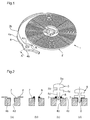
- Steps a) to e) are illustrated in Figure 2 (a) , steps f) and g) at the Figure 2 (b) and steps h) and i) Figures 2 (c) and 2 (d) .
- the figure 3 shows the fixing member 4 with its multilayer metal coating 7.
- the brazing of the piton 5 on the component 1 is precise and reproducible.
- the multilayer metal coating 7 has a high wettability and thus defines a brazing zone in which the solder paste or cream may spread before heating and, especially, in which the metal Molten filler 8 can spread during heating.
- the migration of the filler metal 8 is contained, the latter covering only the multilayered metal coating 7. This prevents propagation of the filler metal 8 over the entire surface of the component 1, which propagation would modify the properties intrinsic material and the aesthetics of the component 1.
- the amount of filler metal 8 deposited is controlled.
- the steps f) and g) are inverted.
- the stencil 6 is for example metal, silicon, ceramic or plastic. Depending on the material chosen, the stencil 6 may be obtained by mechanical or chemical machining, laser cutting, physical or chemical etching or stamping of a plate, for example. A screen printing or photolithography method can also be envisaged to define the stencil aperture (s).
- the multilayer metal coating 7 is solid, that is to say that all its layers are in the solid state. It can be deposited as thin films by PVD (Physical Vapor Deposition), including vacuum evaporation or cathodic sputtering, or CVD (Chemical Vapor Deposition), including ALD (Atomic Layer Deposition) and MVD (molecular vapor phase deposition). It can also be deposited in the form of thick layers by projection, galvanic growth or other.
- PVD Physical Vapor Deposition
- ALD Atomic Layer Deposition
- MVD molecular vapor phase deposition
- the deposition of the multilayer metal coating 7 can be performed on each component after the latter has been separated from the plate of non-metallic material, or simultaneously on all the components while they are still attached to the plate. In the latter case a single stencil covering all the components of the plate and positioned with reference points on the plate can be used.
- the stencil 6 makes it possible to deposit the multilayer metal coating 7 in a localized manner on the component 1.
- the use of a stencil is preferred to the implementation of a photolithography process because of its simplicity and its low cost.
- the present invention does not exclude the implementation of a photolithography method, with a resin mask formed on the component 1.
- the present invention also does not exclude depositing the multilayer metal coating 7 in a non-localized manner. For example, it could cover all the component 1 of the multilayer metal coating 7 and then remove, for example by laser, said coating 7 except in the brazing area. It would also be possible to leave the multilayer metal coating 7 on all the component 1, with however the disadvantages mentioned above related to the propagation of the filler metal 8.
- the multilayer metal coating 7 comprises a first metal layer 7a deposited on the component 1 and a second metal layer 7b deposited on the first metal layer 7a.
- the first metal layer 7a is made of a material that adheres well (better than the material of the second metal layer 7b) to the non-metallic material of the component 1.
- the second metal layer 7b is made of a material having good wettability (better wettability than the first metal layer 7a and the component 1) by the filler metal 8.
- adhesion and wettability properties can be measured by conventional tests such as, for adhesion, a measurement by nanoindentation on section (or interfacial), a nanorayure measurement or a micro-scratch test, and for wettability, a measure of the contact angle between the surface of a droplet and the surface of the sample or a method of hanging drop or drop scale with a blood pressure monitor.
- the multilayer metal coating 7 combines these properties of adhesion and wettability for improved holding of the fastener 4 on the stud 5.
- the first metal layer 7a allows the second metallic layer 7b, wettable by the filler metal 8, to firmly adhere to the component 1. These two layers 7a, 7b remain in the solid state during heating (step i)).
- the first metal layer 7a is for example chromium, titanium or tantalum, or an alloy based on one or more of these metals.
- the second metal layer 7b is for example copper, platinum, palladium, silver, gold, nickel, molybdenum, rhodium, tungsten, tin, iron, cobalt, or iridium, or an alloy based on one or more of these metals for example a gold / tin or silver / tin alloy.
- the multilayer metal coating 7 may further comprise a third metal layer 7c, typically very thin, deposited on the second metal layer 7b to protect the second metal layer 7b of the oxidation. Indeed, the oxidation of a surface generally degrades the wettability.
- the third metal layer 7c is sacrificial, it mixes with the filler metal 8 during heating (step i)). It preferably has a wettability by the filler metal 8 greater than that of the first metal layer 7a and preferably even greater than that of the second metal layer 7b.
- This third metal layer 7c may be gold, nickel, platinum, iridium, osmium, palladium, rhodium, ruthenium or molybdenum, or an alloy based on one or more of these metals. It is particularly useful in the case of a second metal layer 7b copper or nickel.
- a metal that reacts physico-chemically with the material of the third metal layer 7c is chosen as filler metal 8.
- a metal for example a tin-based alloy, will form an alloy with the material of the third metal layer 7c thus causing the latter to disappear.
- One or more intermediate layers may also be provided between the first metal layer 7a and the second metal layer 7b.
- the second metal layer 7b can serve as diffusion barrier preventing the atoms of the first metal layer 7a (particularly the chromium atoms or titanium) to migrate to the third metal layer 7c, when present, and to the filler metal 8 during heating (step i)).
- Such a migration can indeed reduce the adhesion of the first metal layer 7a to the component 1 or weaken the solder.
- the materials that can act as a diffusion barrier and thus constitute such a second metal layer 7b mention may be made of: nickel, tantalum, platinum, palladium, vanadium, iridium, tungsten, cobalt, hafnium, zirconium, ruthenium or niobium, or alloy based on one or more of these metals.
- the multilayer metal coating 7 does not comprise a third metal layer 7c and the second metal layer 7b is sacrificial, in other words it is very thin and its material is chosen to mix with the filler metal 8 during heating (step i)).
- This second metal layer 7b then performs the function of protecting the first metal layer 7a of the oxidation.
- the wettability of the second metal layer 7b by the filler metal 8 is preferably greater than that of the first metal layer 7a.
- Examples of materials for the second metal layer 7b in this variant are the following: gold, nickel, platinum, iridium, osmium, palladium, rhodium, ruthenium or molybdenum, or an alloy based on one or more of these metals.
- the method according to the invention comprises the steps a) to i) described above with the exception of step g) of depositing the filler metal 8.
- the filler metal is part of the multilayer metal coating 7.
- the multilayer metal coating 7 in fact comprises the second metal layer 7b (not coated with the third layer 7c ) whose material is chosen to melt during heating and form the filler metal for brazing.
- the material of the second metal layer 7b is for example a gold / tin alloy.
- This embodiment has the advantage of dry work, no paste or solder cream, so no flux or other viscous liquid is used.
- the amount of filler metal is perfectly controlled since it is determined by the thickness of the second metal layer 7b deposited by PVD or CVD, projection or galvanic growth.
- this embodiment allows self-centering of the stud 5 in the hole 4d thanks to the controlled thickness of the second metal layer 7b and the very small clearance that may exist between the wall of the hole 4d and the stud 5 before the brazing.
- an intermediate layer is deposited between the first metal layer 7a and the second metal layer 7b to serve as diffusion barrier.
- each layer of the multilayer metal coating 7 is typically less than 10 ⁇ m, preferably less than 5 ⁇ m or, for the first layer 7 a, less than 1 ⁇ m.
- the optional sacrificial layer, 7b or 7c according to the variant used, may have a thickness of less than 50 nm.
- the present invention is not limited to the attachment of a hairspring. It can in fact also apply, for example, to the attachment of a hairspring to the axis of pendulum, fixing a wheel, a pinion, an escapement anchor, a balance, a lever or a lever to its axis of rotation, the fixing of metal weights on a balance to increase the inertia or more generally to the assembly of two components watchmaker.
- the present invention is also not limited to the assembly of a nonmetallic timepiece component and a metal timepiece component. Both components can indeed be non-metallic.
- the multilayer metal coating according to the invention can be deposited on the two components, or the multilayer metal coating according to the invention can be deposited on one of the two components and another type of metal coating on the two components. other component.
- the first component may comprise a last gold layer and the second component may comprise a final tin layer.
- the first layers or layers of attachment can also be different. It is appropriate to predetermine the thicknesses of the attachment layers to improve the strength of the assembly.
- the present invention can also be applied to the assembly of both metal watch components, the multilayer metal coating deposited on one or both components to improve the strength of the assembly and the quality of the brazing.
Landscapes
- Engineering & Computer Science (AREA)
- Physics & Mathematics (AREA)
- General Physics & Mathematics (AREA)
- Mechanical Engineering (AREA)
- Manufacturing & Machinery (AREA)
- Metallurgy (AREA)
- Chemical & Material Sciences (AREA)
- Materials Engineering (AREA)
- Other Surface Treatments For Metallic Materials (AREA)
Abstract
Procédé d'assemblage d'un premier composant horloger (1) fait en un matériau de base, typiquement non métallique, et d'un deuxième composant horloger (5). Le procédé comprend les étapes suivantes : a) déposer un revêtement métallique multicouche (7) sur au moins une partie du premier composant horloger (1), le revêtement métallique multicouche (7) comprenant une première couche (7a) en contact avec le premier composant horloger (1) et faite en un premier matériau métallique et, sur la première couche (7a), une deuxième couche (7b) faite en un deuxième matériau métallique ; et b) braser le deuxième composant horloger (5) à l'au moins une partie du premier composant horloger (1). Dans un exemple de réalisation le premier matériau métallique est choisi pour avoir sur le matériau de base une meilleure adhérence que le deuxième matériau métallique et le deuxième matériau métallique est choisi pour avoir une meilleure mouillabilité que le premier matériau métallique. La deuxième couche (7b) peut aussi être une couche sacrificielle de protection ou constituer le métal d'apport pour le brasage. Le premier composant horloger (1) est par exemple un spiral et le deuxième composant horloger (5) un piton.A method of assembling a first watch component (1) made of a base material, typically non-metallic, and a second watch component (5). The method comprises the following steps: a) depositing a multilayer metal coating (7) on at least a part of the first timepiece component (1), the multilayer metal coating (7) comprising a first layer (7a) in contact with the first component watchmaker (1) and made of a first metallic material and, on the first layer (7a), a second layer (7b) made of a second metallic material; and b) brazing the second watch component (5) to the at least a portion of the first watch component (1). In an exemplary embodiment, the first metallic material is chosen to have on the base material a better adhesion than the second metallic material and the second metallic material is chosen to have better wettability than the first metallic material. The second layer (7b) may also be a protective sacrificial layer or constitute the filler metal for brazing. The first watch component (1) is for example a spiral and the second watch component (5) a peak.
Description
La présente invention concerne un procédé d'assemblage de composants horlogers.The present invention relates to a method of assembling watch components.
Dans le domaine horloger, on utilise de plus en plus des matériaux non métalliques tels que le silicium, le diamant, des céramiques, des verres ou des verres métalliques. Grâce à leurs propriétés avantageuses en termes notamment de densité, de coefficient de frottement et d'insensibilité aux champs magnétiques, ces matériaux ont largement contribué à améliorer la précision et le rendement des mécanismes horlogers. Cependant ces matériaux se prêtent mal à certaines techniques d'assemblage. Ne pouvant pas être chassés en raison de leur fragilité, ils sont généralement collés ou montés élastiquement. Le collage entraîne des problèmes de pollution dans le mécanisme et de mauvaise tenue à long terme. Le montage élastique, quant à lui, n'autorise pas la transmission de couples élevés entre les deux composants assemblés.In the field of watchmaking, non-metallic materials such as silicon, diamond, ceramics, glasses or metallic glasses are increasingly being used. Thanks to their advantageous properties in terms in particular of density, coefficient of friction and insensitivity to magnetic fields, these materials have largely contributed to improving the accuracy and efficiency of the watch mechanisms. However, these materials do not lend themselves to certain assembly techniques. Can not be hunted because of their fragility, they are usually glued or mounted elastically. Bonding leads to pollution problems in the mechanism and poor long-term performance. The elastic assembly, meanwhile, does not allow the transmission of high torque between the two assembled components.
On connaît par le brevet
La présente invention concerne plus particulièrement un procédé de brasage de deux composants horlogers. Par « composant horloger » on entend un composant dans son entier, par exemple un spiral ou un piton ; on entend aussi une partie d'un composant horloger, par exemple un crochet qui est sur un arbre de barillet, ou une tirette qui est sur une tige de remontoir. Par « brasage » on entend une opération d'assemblage à l'aide d'un métal d'apport (« brasure ») ayant une température de fusion inférieure à celle des pièces à réunir, le métal d'apport mouillant les surfaces des pièces (zone de brasage) à réunir.The present invention relates more particularly to a process for brazing two watch components. By "watch component" means a component in its entirety, for example a spiral or a stud; we also hear a part of a watch component, for example a hook which is on a barrel shaft, or a pull which is on a winding stem. By "brazing" we means an assembly operation using a filler metal ("solder") having a lower melting temperature than the parts to be joined, the filler metal wetting the surfaces of the parts (brazing zone) to gather.
Le caractère mouillant des métaux d'apport varie en fonction des matériaux sur lesquels ils sont déposés. Certains matériaux ont une mauvaise mouillabilité vis-à-vis des métaux d'apport disponibles dans le commerce. Pour le brasage d'une pièce non métallique, il convient donc de choisir un dépôt métallique qui présente à la fois une bonne adhérence sur le matériau de base et une bonne mouillabilité par le métal d'apport, ce que le procédé décrit dans le brevet
La présente invention vise à proposer un procédé amélioré d'assemblage d'un premier composant horloger fait en un matériau de base, typiquement non métallique, et d'un deuxième composant horloger. Le procédé selon l'invention est caractérisé en ce qu'il comprend les étapes suivantes :
- a) déposer un revêtement métallique multicouche sur au moins une partie du premier composant horloger, le revêtement métallique multicouche comprenant une première couche en contact avec le premier composant horloger et faite en un premier matériau métallique et, sur la première couche, une deuxième couche faite en un deuxième matériau métallique différent du premier matériau métallique, et
- b) braser le deuxième composant horloger à ladite au moins une partie du premier composant horloger.
- a) depositing a multilayer metal coating on at least a portion of the first timepiece component, the multilayer metal coating comprising a first layer in contact with the first timepiece component and made of a first metallic material and, on the first layer, a second layer made in a second metallic material different from the first metallic material, and
- b) brazing the second watch component to said at least a portion of the first watch component.
Entre la première couche et la deuxième couche le revêtement métallique multicouche peut comprendre une ou plusieurs couches intermédiaires.Between the first layer and the second layer the multilayered metal coating may comprise one or more intermediate layers.
Selon un premier mode de réalisation de l'invention, l'étape b) comprend les étapes suivantes :
- déposer un métal d'apport sur le revêtement métallique multicouche ;
- faire fondre le métal d'apport pour qu'il lie les premier et deuxième composants horlogers.
- depositing a filler metal on the multilayered metal coating;
- melting the filler metal to connect the first and second watch components.
Le premier matériau métallique peut être choisi pour avoir sur le matériau de base une meilleure adhérence que le deuxième matériau métallique et le deuxième matériau métallique peut être choisi pour avoir une meilleure mouillabilité par le métal d'apport que le premier matériau métallique.The first metallic material may be selected to have a better adhesion to the base material than the second metal material and the second metal material may be chosen to have better wettability by the filler metal than the first metal material.
Le revêtement métallique multicouche peut comprendre en outre, sur la deuxième couche, une troisième couche faite en un troisième matériau métallique différent du deuxième matériau métallique et choisi pour se mélanger au métal d'apport pendant l'étape b), cette troisième couche protégeant la deuxième couche de l'oxydation et préservant ainsi la mouillabilité de la deuxième couche jusqu'à la mise en oeuvre de l'étape b).The multilayer metal coating may further comprise, on the second layer, a third layer made of a third metallic material different from the second metallic material and chosen to mix with the filler metal during step b), this third layer protecting the second layer of the oxidation and thus preserving the wettability of the second layer until the implementation of step b).
En alternative à sa fonction d'augmenter la mouillabilité du revêtement métallique multicouche, ou en plus de cette fonction, la deuxième couche peut servir de barrière de diffusion empêchant pendant l'étape b) la migration d'atomes du premier matériau métallique vers, le cas échéant, la troisième couche et vers le métal d'apport.As an alternative to its function of increasing the wettability of the multilayer metal coating, or in addition to this function, the second layer can serve as diffusion barrier preventing during step b) the migration of atoms of the first metallic material to, the if necessary, the third layer and to the filler metal.
Dans une variante du premier mode de réalisation de l'invention, le deuxième matériau métallique est choisi pour se mélanger au métal d'apport pendant l'étape b) et donc constituer une couche sacrificielle protectrice pour la première couche jusqu'à la mise en oeuvre de l'étape b).In a variant of the first embodiment of the invention, the second metallic material is chosen to mix with the filler metal during step b) and thus constitute a protective sacrificial layer for the first layer until the setting the work of step b).
Selon un deuxième mode de réalisation de l'invention, l'étape b) comprend une étape consistant à faire fondre la deuxième couche du revêtement métallique multicouche pour constituer un métal d'apport (brasure) liant les premier et deuxième composants horlogers, aucun autre métal d'apport n'étant utilisé pour le brasage.According to a second embodiment of the invention, step b) comprises a step of melting the second layer of the multilayer metal coating to form a filler metal (solder) bonding the first and second watch components, no other filler metal being used for brazing.
L'invention propose aussi un mécanisme horloger comprenant un assemblage d'un premier composant horloger et d'un deuxième composant horloger obtenu par le procédé tel que défini ci-dessus.The invention also proposes a clock mechanism comprising an assembly of a first clock component and a second clock component obtained by the method as defined above.
D'autres caractéristiques et avantages de la présente invention apparaîtront à la lecture de la description détaillée suivante faite en référence aux dessins annexés dans lesquels :
- la
figure 1 est une vue en perspective d'un exemple de premier composant horloger selon l'invention, comprenant un spiral, une virole et un organe de fixation à un piton ; - la
figure 2 (figures 2(a) à 2(d) ) est une vue en coupe transversale, suivant la ligne A-A de lafigure 1 , de l'organe de fixation au piton, montrant différentes étapes du procédé selon l'invention pour assembler le premier composant horloger au piton ; - la
figure 3 est une vue en perspective de l'organe de fixation au piton portant un revêtement métallique multicouche ; - la
figure 4 est une vue en coupe transversale, suivant la ligne A-A de lafigure 1 , de l'organe de fixation au piton, montrant les différentes couches du revêtement métallique multicouche.
- the
figure 1 is a perspective view of an example of a first timepiece component according to the invention, comprising a hairspring, a ferrule and a fixing member to a peak; - the
Figure 2 (Figures 2 (a) to 2 (d) ) is a cross-sectional view along the line AA of thefigure 1 , of the bolt fixing member, showing different steps of the method according to the invention for assembling the first clock component to the bolt; - the
figure 3 is a perspective view of the peg fastener with a multilayered metal coating; - the
figure 4 is a cross-sectional view along the line AA of thefigure 1 of the peg fastener, showing the different layers of the multilayer metal coating.
Dans le cadre de la présente invention, on entend par le terme « métal » un métal proprement dit ou un alliage à base de métal.In the context of the present invention, the term "metal" means a metal itself or a metal-based alloy.
La
La présente invention porte notamment sur un procédé permettant d'assembler le composant 1 et le piton 5, c'est-à-dire de fixer l'organe de fixation 4 au piton 5. Comme on peut le voir, l'organe de fixation 4 comprend une lame rigide 4a qui prolonge la lame du spiral 2 et qui est interrompue (comme représenté) ou terminée par un anneau 4b. Le piton 5 comprend successivement une tête 5a, une première partie cylindrique 5b, un épaulement 5c et une deuxième partie cylindrique 5d. La tête 5a et la première partie cylindrique 5b sont destinées respectivement à reposer sur et à traverser le coq de manière connue en soi. L'épaulement 5c est destiné à reposer sur la surface supérieure 4c (tournée vers le coq) de l'anneau 4b. La deuxième partie cylindrique 5d est destinée à s'engager dans le trou 4d de l'anneau 4b. Le piton 5 est métallique.The present invention relates in particular to a method for assembling the
Un premier mode de réalisation du procédé selon l'invention est maintenant décrit en relation avec la
- a) se doter d'un pochoir 6 (« shadow mask » en anglais) dont le motif correspond à la zone du
composant 1 que l'on souhaite métalliser, c'est-à-dire la zone dutrou 4d de l'anneau 4b ; - b) définir des points repères sur le
composant 1 ; - c) positionner le
pochoir 6 sur lecomposant 1 en suivant les points repère ; - d) fixer le pochoir 6
au composant 1 ; - e) déposer un revêtement métallique multicouche 7 (qui sera décrit plus loin) sur l'ensemble pochoir 6 -
composant 1, afin que le revêtement 7 soit présent sur le composant 1 uniquement dans la zone dutrou 4d, plus particulièrement sur la paroi et le bord supérieur dutrou 4d ; - f) retirer le pochoir 6 du composant 1 ;
- g) déposer
un métal d'apport 8 sur le revêtement métallique multicouche 7 ; - h) positionner le piton 5 de telle sorte que la deuxième partie cylindrique 5d soit engagée dans le
trou 4d et que l'épaulement 5c soit en appui sur lasurface supérieure 4c de l'organe de fixation 4 (plus exactement sur le revêtement métallique multicouche 7), et appliquer une pression prédéfinie ; - i) chauffer à une température prédéfinie l'ensemble composant 1 -
piton 5 pour faire fondre le métal d'apport 8 et lier le composant 1 et lepiton 5 ; selon la température choisie le brasage sera tendre (basse température) ou dur (haute température).
- a) obtain a stencil 6 ("shadow mask" in English) whose pattern corresponds to the area of the
component 1 that is to be metallized, that is to say the area of thehole 4d of thering 4b; - b) to define reference points on
component 1; - c) position the
stencil 6 on thecomponent 1 following the reference points; - d) fix the
stencil 6 tocomponent 1; - e) depositing a multilayer metal coating 7 (to be described later) on the stencil assembly 6 -
component 1, so that thecoating 7 is present on thecomponent 1 only in the area of thehole 4d, more particularly on the wall and the upper edge of thehole 4d; - f) removing
stencil 6 fromcomponent 1; - g) depositing a
filler metal 8 on themultilayer metal coating 7; - h) position the
stud 5 so that the secondcylindrical portion 5d is engaged in thehole 4d and that theshoulder 5c bears on theupper surface 4c of the fastener 4 (more precisely on the multilayer metal coating 7), and apply a preset pressure; - i) heating at a predetermined temperature the component assembly 1 -
piton 5 to melt thefiller metal 8 and bind thecomponent 1 and thepeg 5; depending on the chosen temperature, the soldering will be soft (low temperature) or hard (high temperature).
Les étapes a) à e) sont illustrées à la
A l'étape g) le métal d'apport 8 peut être déposé soit manuellement soit par un doseur. Avant le chauffage (étape i)) le métal d'apport 8 est sous la forme d'une poudre métallique ou de billes métalliques suspendue(s) dans un liquide visqueux appelé « flux », l'ensemble formant une pâte ou crème à braser, donc une substance non solide. Lors du chauffage le liquide s'évapore et la poudre métallique fond pour créer une interface métallique entre le composant 1 et le piton 5. Des exemples de matériaux pouvant constituer le métal d'apport 8 sont :
- pour un brasage tendre (température inférieure à 450°C) : alliage à base d'étain, d'indium, de plomb, de bismuth ou d'antimoine comme les alliages étain/bismuth, or/étain, argent/étain, indium/étain, plomb/étain ;
- pour un brasage dur (température supérieure à 450°C) : alliage à base de cuivre, de nickel, d'argent, d'aluminium ou de zinc, par exemple alliage cuivre/argent ou cuivre/argent/nickel.
- for soldering (temperature below 450 ° C): alloy based on tin, indium, lead, bismuth or antimony, such as tin / bismuth alloys, gold / tin, silver / tin, indium / tin, lead / tin;
- for hard brazing (temperature greater than 450 ° C): alloy based on copper, nickel, silver, aluminum or zinc, for example copper / silver or copper / silver / nickel alloy.
Avec le procédé selon l'invention, le brasage du piton 5 sur le composant 1 est précis et reproductible. Au contraire du matériau non métallique formant le composant 1, le revêtement métallique multicouche 7 présente une mouillabilité élevée et délimite ainsi une zone de brasage dans laquelle la pâte ou crème à braser peut s'étaler avant le chauffage et, surtout, dans laquelle le métal d'apport 8 fondu peut s'étaler pendant le chauffage. De ce fait, la migration du métal d'apport 8 est contenue, ce dernier ne recouvrant que le revêtement métallique multicouche 7. On évite donc une propagation du métal d'apport 8 sur toute la surface du composant 1, propagation qui modifierait les propriétés intrinsèques du matériau et l'esthétique du composant 1. De plus, la quantité de métal d'apport 8 déposée est contrôlée.With the process according to the invention, the brazing of the
Dans une variante du premier mode de réalisation de l'invention, les étapes f) et g) sont interverties.In a variant of the first embodiment of the invention, the steps f) and g) are inverted.
Le pochoir 6 est par exemple en métal, silicium, céramique ou plastique. Selon le matériau choisi, le pochoir 6 peut être obtenu par usinage mécanique ou chimique, découpage au laser, gravure physique ou chimique ou étampage d'une plaque, par exemple. Une méthode de type sérigraphie ou photolithographie peut aussi être envisagée pour définir la ou les ouvertures du pochoir.The
Par définition le revêtement métallique multicouche 7 est solide, c'est-à-dire que toutes ses couches sont à l'état solide. Il peut être déposé sous forme de couches minces par PVD (dépôt physique en phase vapeur), y compris évaporation sous vide ou pulvérisation cathodique, ou par CVD (dépôt chimique en phase vapeur), y compris ALD (dépôt de couches atomiques) et MVD (dépôt moléculaire en phase vapeur). Il peut aussi être déposé sous forme de couches épaisses par projection, croissance galvanique ou autre.By definition, the
En pratique, plusieurs composants sont réalisés à partir d'une même plaque de matériau non métallique. Le dépôt du revêtement métallique multicouche 7 peut être réalisé sur chaque composant après que ce dernier a été séparé de la plaque de matériau non métallique, ou simultanément sur tous les composants alors qu'ils sont encore attachés à la plaque. Dans ce dernier cas un unique pochoir recouvrant tous les composants de la plaque et positionné par rapport à des points repères sur la plaque peut être employé.In practice, several components are made from the same plate of non-metallic material. The deposition of the
Le pochoir 6 permet de déposer le revêtement métallique multicouche 7 de manière localisée sur le composant 1. Dans la présente invention l'usage d'un pochoir est préféré à la mise en oeuvre d'un procédé de photolithographie en raison de sa simplicité et de son faible coût. La présente invention n'exclut toutefois pas la mise en oeuvre d'un procédé de photolithographie, avec masque en résine formé sur le composant 1. La présente invention n'exclut pas non plus de déposer le revêtement métallique multicouche 7 de manière non localisée. Par exemple, on pourrait recouvrir tout le composant 1 du revêtement métallique multicouche 7 puis enlever, par exemple par laser, ledit revêtement 7 sauf dans la zone du brasage. On pourrait aussi laisser le revêtement métallique multicouche 7 sur tout le composant 1, avec cependant pour conséquence les inconvénients mentionnés plus haut liés à la propagation du métal d'apport 8.The
Comme montré à la
Ces propriétés d'adhérence et de mouillabilité peuvent être mesurées par des tests classiques tels que, pour l'adhérence, une mesure par nanoindentation sur coupe (ou interfaciale), une mesure par nanorayure ou une mesure par micro scratch test, et pour la mouillabilité, une mesure de l'angle de contact entre la surface d'une goutte et la surface de l'échantillon ou une méthode de goutte pendante ou de pesée de goutte avec un tensiomètre.These adhesion and wettability properties can be measured by conventional tests such as, for adhesion, a measurement by nanoindentation on section (or interfacial), a nanorayure measurement or a micro-scratch test, and for wettability, a measure of the contact angle between the surface of a droplet and the surface of the sample or a method of hanging drop or drop scale with a blood pressure monitor.
Ainsi, le revêtement métallique multicouche 7 selon l'invention associe ces propriétés d'adhérence et de mouillabilité pour une tenue améliorée de l'organe de fixation 4 sur le piton 5. La première couche métallique 7a permet à la deuxième couche métallique 7b, mouillable par le métal d'apport 8, d'adhérer fermement au composant 1. Ces deux couches 7a, 7b restent à l'état solide pendant le chauffage (étape i)).Thus, the
La première couche métallique 7a est par exemple en chrome, titane ou tantale, ou en un alliage à base d'un ou plusieurs de ces métaux. La deuxième couche métallique 7b est par exemple en cuivre, platine, palladium, argent, or, nickel, molybdène, rhodium, tungstène, étain, fer, cobalt, ou iridium, ou en un alliage à base d'un ou plusieurs de ces métaux, par exemple un alliage or/étain ou argent/étain.The
Le revêtement métallique multicouche 7 peut comprendre en outre une troisième couche métallique 7c, typiquement très mince, déposée sur la deuxième couche métallique 7b pour protéger la deuxième couche métallique 7b de l'oxydation. En effet, l'oxydation d'une surface dégrade généralement la mouillabilité. La troisième couche métallique 7c est sacrificielle, elle se mélange au métal d'apport 8 pendant le chauffage (étape i)). Elle a de préférence une mouillabilité par le métal d'apport 8 supérieure à celle de la première couche métallique 7a et de préférence encore supérieure à celle de la deuxième couche métallique 7b. Cette troisième couche métallique 7c peut être en or, nickel, platine, iridium, osmium, palladium, rhodium, ruthénium ou molybdène, ou en un alliage à base d'un ou plusieurs de ces métaux. Elle est particulièrement utile dans le cas d'une deuxième couche métallique 7b en cuivre ou en nickel.The
Pour que la troisième couche métallique 7c soit sacrificielle, on choisit comme métal d'apport 8 un métal qui réagit de manière physico-chimique avec le matériau de la troisième couche métallique 7c. Un tel métal, par exemple un alliage à base d'étain, formera un alliage avec le matériau de la troisième couche métallique 7c entraînant ainsi la disparition de cette dernière.In order for the
Une ou plusieurs couches intermédiaires peuvent également être prévues entre la première couche métallique 7a et la deuxième couche métallique 7b.One or more intermediate layers may also be provided between the
En alternative à sa fonction d'augmenter la mouillabilité du revêtement métallique multicouche 7, ou en plus de cette fonction, la deuxième couche métallique 7b peut servir de barrière de diffusion empêchant les atomes de la première couche métallique 7a (particulièrement les atomes de chrome ou de titane) de migrer vers la troisième couche métallique 7c, lorsqu'elle est présente, et vers le métal d'apport 8 pendant le chauffage (étape i)). Une telle migration peut en effet diminuer l'adhérence de la première couche métallique 7a sur le composant 1 ou fragiliser la brasure. Parmi les matériaux pouvant faire office de barrière de diffusion et constituer ainsi une telle deuxième couche métallique 7b, on peut citer : nickel, tantale, platine, palladium, vanadium, iridium, tungstène, cobalt, hafnium, zirconium, ruthénium ou niobium, ou alliage à base d'un ou plusieurs de ces métaux.As an alternative to its function of increasing the wettability of the
Dans une variante du premier mode de réalisation de l'invention, le revêtement métallique multicouche 7 ne comporte pas de troisième couche métallique 7c et la deuxième couche métallique 7b est sacrificielle, en d'autres termes elle est très mince et son matériau est choisi pour se mélanger au métal d'apport 8 pendant le chauffage (étape i)). Cette deuxième couche métallique 7b remplit alors la fonction de protéger la première couche métallique 7a de l'oxydation. La mouillabilité de la deuxième couche métallique 7b par le métal d'apport 8 est de préférence supérieure à celle de la première couche métallique 7a. Des exemples de matériaux pour la deuxième couche métallique 7b dans cette variante sont les suivants : or, nickel, platine, iridium, osmium, palladium, rhodium, ruthénium ou molybdène, ou un alliage à base d'un ou plusieurs de ces métaux.In a variant of the first embodiment of the invention, the
Selon un deuxième mode de réalisation, le procédé selon l'invention comprend les étapes a) à i) décrites précédemment à l'exception de l'étape g) consistant à déposer le métal d'apport 8. Dans ce deuxième mode de réalisation le métal d'apport (brasure) fait partie du revêtement métallique multicouche 7. En plus de la première couche métallique ou couche d'accrochage 7a, le revêtement métallique multicouche 7 comprend en effet la deuxième couche métallique 7b (non revêtue de la troisième couche 7c) dont le matériau est choisi pour fondre pendant le chauffage et constituer le métal d'apport pour le brasage. Le matériau de la deuxième couche métallique 7b est par exemple un alliage or/étain. Ce mode de réalisation présente l'avantage d'un travail à sec, aucune pâte ou crème à braser, donc aucun flux ou autre liquide visqueux, n'étant utilisé. De plus la quantité de métal d'apport est parfaitement contrôlée puisqu'elle est déterminée par l'épaisseur de la deuxième couche métallique 7b déposée par PVD ou CVD, projection ou croissance galvanique. En outre, ce mode de réalisation permet un auto-centrage du piton 5 dans le trou 4d grâce à l'épaisseur contrôlée de la deuxième couche métallique 7b et au très faible jeu pouvant exister entre la paroi du trou 4d et le piton 5 avant le brasage.According to a second embodiment, the method according to the invention comprises the steps a) to i) described above with the exception of step g) of depositing the
Dans une variante du deuxième mode de réalisation, une couche intermédiaire est déposée entre la première couche métallique 7a et la deuxième couche métallique 7b pour servir de barrière de diffusion.In a variant of the second embodiment, an intermediate layer is deposited between the
Dans la présente invention l'épaisseur de chaque couche du revêtement métallique multicouche 7 est typiquement inférieure à 10 µm, de préférence inférieure à 5 µm voire, pour la première couche 7a, inférieure à 1 µm. L'éventuelle couche sacrificielle, 7b ou 7c selon la variante utilisée, peut avoir une épaisseur inférieure à 50 nm.In the present invention, the thickness of each layer of the
La présente invention n'est pas limitée à la fixation d'un spiral au piton. Elle peut en effet s'appliquer aussi, par exemple, à la fixation d'un spiral à l'axe de balancier, à la fixation d'une roue, d'un pignon, d'une ancre d'échappement, d'un balancier, d'une bascule ou d'un levier à son axe de rotation, à la fixation de masselottes métalliques sur un balancier pour en augmenter l'inertie ou plus généralement à l'assemblage de deux composants horlogers.The present invention is not limited to the attachment of a hairspring. It can in fact also apply, for example, to the attachment of a hairspring to the axis of pendulum, fixing a wheel, a pinion, an escapement anchor, a balance, a lever or a lever to its axis of rotation, the fixing of metal weights on a balance to increase the inertia or more generally to the assembly of two components watchmaker.
La présente invention n'est pas non plus limitée à l'assemblage d'un composant horloger non métallique et d'un composant horloger métallique. Les deux composants peuvent en effet être non métalliques. Dans ce cas, avant le brasage, on pourra déposer le revêtement métallique multicouche selon l'invention sur les deux composants, ou déposer le revêtement métallique multicouche selon l'invention sur l'un des deux composants et un autre type de revêtement métallique sur l'autre composant. On pourra en particulier utiliser des matériaux métalliques différents pour les deux composants. Par exemple le premier composant peut comprendre une dernière couche en or et le deuxième composant peut comprendre une dernière couche en étain. Les premières couches ou couches d'accrochage peuvent aussi être différentes. Il est opportun de prédéterminer les épaisseurs des couches d'accrochage afin d'améliorer la tenue de l'assemblage.The present invention is also not limited to the assembly of a nonmetallic timepiece component and a metal timepiece component. Both components can indeed be non-metallic. In this case, before brazing, the multilayer metal coating according to the invention can be deposited on the two components, or the multilayer metal coating according to the invention can be deposited on one of the two components and another type of metal coating on the two components. other component. In particular, it will be possible to use different metallic materials for the two components. For example, the first component may comprise a last gold layer and the second component may comprise a final tin layer. The first layers or layers of attachment can also be different. It is appropriate to predetermine the thicknesses of the attachment layers to improve the strength of the assembly.
Enfin, la présente invention peut également s'appliquer à l'assemblage de composants horlogers tous deux métalliques, le revêtement métallique multicouche déposé sur l'un des composants ou sur les deux permettant d'améliorer la tenue de l'assemblage et la qualité du brasage.Finally, the present invention can also be applied to the assembly of both metal watch components, the multilayer metal coating deposited on one or both components to improve the strength of the assembly and the quality of the brazing.
Claims (25)
Priority Applications (2)
| Application Number | Priority Date | Filing Date | Title |
|---|---|---|---|
| EP16193656.2A EP3309624B1 (en) | 2016-10-13 | 2016-10-13 | Method for assembling timepiece components |
| CH01369/16A CH713026A2 (en) | 2016-10-13 | 2016-10-13 | Method of assembling watch components |
Applications Claiming Priority (1)
| Application Number | Priority Date | Filing Date | Title |
|---|---|---|---|
| EP16193656.2A EP3309624B1 (en) | 2016-10-13 | 2016-10-13 | Method for assembling timepiece components |
Publications (2)
| Publication Number | Publication Date |
|---|---|
| EP3309624A1 true EP3309624A1 (en) | 2018-04-18 |
| EP3309624B1 EP3309624B1 (en) | 2019-09-04 |
Family
ID=57133057
Family Applications (1)
| Application Number | Title | Priority Date | Filing Date |
|---|---|---|---|
| EP16193656.2A Active EP3309624B1 (en) | 2016-10-13 | 2016-10-13 | Method for assembling timepiece components |
Country Status (2)
| Country | Link |
|---|---|
| EP (1) | EP3309624B1 (en) |
| CH (1) | CH713026A2 (en) |
Cited By (2)
| Publication number | Priority date | Publication date | Assignee | Title |
|---|---|---|---|---|
| WO2020148626A1 (en) | 2019-01-16 | 2020-07-23 | Patek Philippe Sa Geneve | Method for brazing clock-making components |
| EP3896534A1 (en) | 2020-04-17 | 2021-10-20 | Patek Philippe SA Genève | Partly transparent timepiece hand and method for manufacturing same |
Families Citing this family (1)
| Publication number | Priority date | Publication date | Assignee | Title |
|---|---|---|---|---|
| EP3800511B1 (en) * | 2019-10-02 | 2022-05-18 | Nivarox-FAR S.A. | Pivoting shaft for a regulating organ |
Citations (4)
| Publication number | Priority date | Publication date | Assignee | Title |
|---|---|---|---|---|
| EP0732635A1 (en) | 1995-03-17 | 1996-09-18 | C.S.E.M. Centre Suisse D'electronique Et De Microtechnique Sa | Micromechanical element and process for its manufacture |
| EP1422436A1 (en) | 2002-11-25 | 2004-05-26 | CSEM Centre Suisse d'Electronique et de Microtechnique SA | Spiral watch spring and its method of production |
| FR2952314A1 (en) * | 2009-11-12 | 2011-05-13 | Sagem Defense Securite | BRAZING METHOD, GYROSCOPE AND BRAZED PART |
| CH707884A2 (en) * | 2013-04-12 | 2014-10-15 | Patek Philippe Sa Geneve | watch Spiral fragile material. |
-
2016
- 2016-10-13 EP EP16193656.2A patent/EP3309624B1/en active Active
- 2016-10-13 CH CH01369/16A patent/CH713026A2/en not_active Application Discontinuation
Patent Citations (4)
| Publication number | Priority date | Publication date | Assignee | Title |
|---|---|---|---|---|
| EP0732635A1 (en) | 1995-03-17 | 1996-09-18 | C.S.E.M. Centre Suisse D'electronique Et De Microtechnique Sa | Micromechanical element and process for its manufacture |
| EP1422436A1 (en) | 2002-11-25 | 2004-05-26 | CSEM Centre Suisse d'Electronique et de Microtechnique SA | Spiral watch spring and its method of production |
| FR2952314A1 (en) * | 2009-11-12 | 2011-05-13 | Sagem Defense Securite | BRAZING METHOD, GYROSCOPE AND BRAZED PART |
| CH707884A2 (en) * | 2013-04-12 | 2014-10-15 | Patek Philippe Sa Geneve | watch Spiral fragile material. |
Cited By (2)
| Publication number | Priority date | Publication date | Assignee | Title |
|---|---|---|---|---|
| WO2020148626A1 (en) | 2019-01-16 | 2020-07-23 | Patek Philippe Sa Geneve | Method for brazing clock-making components |
| EP3896534A1 (en) | 2020-04-17 | 2021-10-20 | Patek Philippe SA Genève | Partly transparent timepiece hand and method for manufacturing same |
Also Published As
| Publication number | Publication date |
|---|---|
| CH713026A2 (en) | 2018-04-13 |
| EP3309624B1 (en) | 2019-09-04 |
Similar Documents
| Publication | Publication Date | Title |
|---|---|---|
| EP1991916B1 (en) | Micromechanical piece with form opening for assembly on a spindle | |
| EP3309624B1 (en) | Method for assembling timepiece components | |
| CH699780B1 (en) | of self-compensating balance spring watch. | |
| CH699680B1 (en) | Device for fixing a fragile movable on a support member. | |
| WO2008135817A2 (en) | Timepiece component and method for making same | |
| CH700059A2 (en) | Curve elevation hairspring i.e. Breguet hairspring, for movement of timepiece, has elevation device placed between external spire and terminal curve, and two unique parts integrated for increasing precision of development of hairspring | |
| EP2725000A1 (en) | Selectively conductive ceramic coated with a metal material | |
| EP3182212B1 (en) | Composite part with resilient means under stress | |
| EP3115852B1 (en) | Timepiece component having a part with improved welding surface | |
| EP3502784A1 (en) | Timepiece resonator with flexible guide | |
| CH700640B1 (en) | Timepiece leaner and stronger. | |
| EP3152625B1 (en) | Timepiece exterior part made of welded materials | |
| EP2743781A1 (en) | Device for assembly by locking a joint | |
| EP2860591A1 (en) | Assembly system using a conical resilient locking member | |
| EP2631721A1 (en) | Diamond-covered titanium clock components | |
| WO2020148626A1 (en) | Method for brazing clock-making components | |
| CH708067B1 (en) | of self-compensating balance spring watch. | |
| EP2320280A1 (en) | Anchor for clock escapement system | |
| EP3037893B1 (en) | Micromechanical or clock component with flexible guidance | |
| EP3642496B1 (en) | Modular mechanical part | |
| CH707884A2 (en) | watch Spiral fragile material. | |
| EP3751356B1 (en) | Improved timepiece component | |
| EP3825782B1 (en) | Reinforced timepiece component | |
| EP3112952B1 (en) | Manufacturing method comprising a modified mounting step | |
| CH707883A2 (en) | Body exhaust for clockwork. |
Legal Events
| Date | Code | Title | Description |
|---|---|---|---|
| PUAI | Public reference made under article 153(3) epc to a published international application that has entered the european phase |
Free format text: ORIGINAL CODE: 0009012 |
|
| STAA | Information on the status of an ep patent application or granted ep patent |
Free format text: STATUS: THE APPLICATION HAS BEEN PUBLISHED |
|
| AK | Designated contracting states |
Kind code of ref document: A1 Designated state(s): AL AT BE BG CH CY CZ DE DK EE ES FI FR GB GR HR HU IE IS IT LI LT LU LV MC MK MT NL NO PL PT RO RS SE SI SK SM TR |
|
| AX | Request for extension of the european patent |
Extension state: BA ME |
|
| STAA | Information on the status of an ep patent application or granted ep patent |
Free format text: STATUS: REQUEST FOR EXAMINATION WAS MADE |
|
| REG | Reference to a national code |
Ref country code: HK Ref legal event code: DE Ref document number: 1247673 Country of ref document: HK |
|
| 17P | Request for examination filed |
Effective date: 20180905 |
|
| RBV | Designated contracting states (corrected) |
Designated state(s): AL AT BE BG CH CY CZ DE DK EE ES FI FR GB GR HR HU IE IS IT LI LT LU LV MC MK MT NL NO PL PT RO RS SE SI SK SM TR |
|
| RIC1 | Information provided on ipc code assigned before grant |
Ipc: G04B 17/06 20060101ALI20190108BHEP Ipc: G04B 15/14 20060101ALI20190108BHEP Ipc: G04B 1/14 20060101AFI20190108BHEP Ipc: G04B 17/32 20060101ALI20190108BHEP |
|
| GRAP | Despatch of communication of intention to grant a patent |
Free format text: ORIGINAL CODE: EPIDOSNIGR1 |
|
| STAA | Information on the status of an ep patent application or granted ep patent |
Free format text: STATUS: GRANT OF PATENT IS INTENDED |
|
| INTG | Intention to grant announced |
Effective date: 20190402 |
|
| GRAS | Grant fee paid |
Free format text: ORIGINAL CODE: EPIDOSNIGR3 |
|
| GRAA | (expected) grant |
Free format text: ORIGINAL CODE: 0009210 |
|
| STAA | Information on the status of an ep patent application or granted ep patent |
Free format text: STATUS: THE PATENT HAS BEEN GRANTED |
|
| AK | Designated contracting states |
Kind code of ref document: B1 Designated state(s): AL AT BE BG CH CY CZ DE DK EE ES FI FR GB GR HR HU IE IS IT LI LT LU LV MC MK MT NL NO PL PT RO RS SE SI SK SM TR |
|
| REG | Reference to a national code |
Ref country code: GB Ref legal event code: FG4D Free format text: NOT ENGLISH |
|
| REG | Reference to a national code |
Ref country code: CH Ref legal event code: EP |
|
| REG | Reference to a national code |
Ref country code: AT Ref legal event code: REF Ref document number: 1176219 Country of ref document: AT Kind code of ref document: T Effective date: 20190915 |
|
| REG | Reference to a national code |
Ref country code: DE Ref legal event code: R096 Ref document number: 602016019795 Country of ref document: DE |
|
| REG | Reference to a national code |
Ref country code: CH Ref legal event code: NV Representative=s name: MICHELI AND CIE SA, CH |
|
| REG | Reference to a national code |
Ref country code: IE Ref legal event code: FG4D Free format text: LANGUAGE OF EP DOCUMENT: FRENCH |
|
| REG | Reference to a national code |
Ref country code: NL Ref legal event code: MP Effective date: 20190904 |
|
| REG | Reference to a national code |
Ref country code: LT Ref legal event code: MG4D |
|
| PG25 | Lapsed in a contracting state [announced via postgrant information from national office to epo] |
Ref country code: LT Free format text: LAPSE BECAUSE OF FAILURE TO SUBMIT A TRANSLATION OF THE DESCRIPTION OR TO PAY THE FEE WITHIN THE PRESCRIBED TIME-LIMIT Effective date: 20190904 Ref country code: SE Free format text: LAPSE BECAUSE OF FAILURE TO SUBMIT A TRANSLATION OF THE DESCRIPTION OR TO PAY THE FEE WITHIN THE PRESCRIBED TIME-LIMIT Effective date: 20190904 Ref country code: BG Free format text: LAPSE BECAUSE OF FAILURE TO SUBMIT A TRANSLATION OF THE DESCRIPTION OR TO PAY THE FEE WITHIN THE PRESCRIBED TIME-LIMIT Effective date: 20191204 Ref country code: FI Free format text: LAPSE BECAUSE OF FAILURE TO SUBMIT A TRANSLATION OF THE DESCRIPTION OR TO PAY THE FEE WITHIN THE PRESCRIBED TIME-LIMIT Effective date: 20190904 Ref country code: NO Free format text: LAPSE BECAUSE OF FAILURE TO SUBMIT A TRANSLATION OF THE DESCRIPTION OR TO PAY THE FEE WITHIN THE PRESCRIBED TIME-LIMIT Effective date: 20191204 Ref country code: HR Free format text: LAPSE BECAUSE OF FAILURE TO SUBMIT A TRANSLATION OF THE DESCRIPTION OR TO PAY THE FEE WITHIN THE PRESCRIBED TIME-LIMIT Effective date: 20190904 |
|
| PG25 | Lapsed in a contracting state [announced via postgrant information from national office to epo] |
Ref country code: RS Free format text: LAPSE BECAUSE OF FAILURE TO SUBMIT A TRANSLATION OF THE DESCRIPTION OR TO PAY THE FEE WITHIN THE PRESCRIBED TIME-LIMIT Effective date: 20190904 Ref country code: LV Free format text: LAPSE BECAUSE OF FAILURE TO SUBMIT A TRANSLATION OF THE DESCRIPTION OR TO PAY THE FEE WITHIN THE PRESCRIBED TIME-LIMIT Effective date: 20190904 Ref country code: AL Free format text: LAPSE BECAUSE OF FAILURE TO SUBMIT A TRANSLATION OF THE DESCRIPTION OR TO PAY THE FEE WITHIN THE PRESCRIBED TIME-LIMIT Effective date: 20190904 Ref country code: GR Free format text: LAPSE BECAUSE OF FAILURE TO SUBMIT A TRANSLATION OF THE DESCRIPTION OR TO PAY THE FEE WITHIN THE PRESCRIBED TIME-LIMIT Effective date: 20191205 Ref country code: ES Free format text: LAPSE BECAUSE OF FAILURE TO SUBMIT A TRANSLATION OF THE DESCRIPTION OR TO PAY THE FEE WITHIN THE PRESCRIBED TIME-LIMIT Effective date: 20190904 |
|
| REG | Reference to a national code |
Ref country code: AT Ref legal event code: MK05 Ref document number: 1176219 Country of ref document: AT Kind code of ref document: T Effective date: 20190904 |
|
| PG25 | Lapsed in a contracting state [announced via postgrant information from national office to epo] |
Ref country code: NL Free format text: LAPSE BECAUSE OF FAILURE TO SUBMIT A TRANSLATION OF THE DESCRIPTION OR TO PAY THE FEE WITHIN THE PRESCRIBED TIME-LIMIT Effective date: 20190904 Ref country code: AT Free format text: LAPSE BECAUSE OF FAILURE TO SUBMIT A TRANSLATION OF THE DESCRIPTION OR TO PAY THE FEE WITHIN THE PRESCRIBED TIME-LIMIT Effective date: 20190904 Ref country code: PL Free format text: LAPSE BECAUSE OF FAILURE TO SUBMIT A TRANSLATION OF THE DESCRIPTION OR TO PAY THE FEE WITHIN THE PRESCRIBED TIME-LIMIT Effective date: 20190904 Ref country code: IT Free format text: LAPSE BECAUSE OF FAILURE TO SUBMIT A TRANSLATION OF THE DESCRIPTION OR TO PAY THE FEE WITHIN THE PRESCRIBED TIME-LIMIT Effective date: 20190904 Ref country code: PT Free format text: LAPSE BECAUSE OF FAILURE TO SUBMIT A TRANSLATION OF THE DESCRIPTION OR TO PAY THE FEE WITHIN THE PRESCRIBED TIME-LIMIT Effective date: 20200106 Ref country code: EE Free format text: LAPSE BECAUSE OF FAILURE TO SUBMIT A TRANSLATION OF THE DESCRIPTION OR TO PAY THE FEE WITHIN THE PRESCRIBED TIME-LIMIT Effective date: 20190904 Ref country code: RO Free format text: LAPSE BECAUSE OF FAILURE TO SUBMIT A TRANSLATION OF THE DESCRIPTION OR TO PAY THE FEE WITHIN THE PRESCRIBED TIME-LIMIT Effective date: 20190904 |
|
| PG25 | Lapsed in a contracting state [announced via postgrant information from national office to epo] |
Ref country code: SM Free format text: LAPSE BECAUSE OF FAILURE TO SUBMIT A TRANSLATION OF THE DESCRIPTION OR TO PAY THE FEE WITHIN THE PRESCRIBED TIME-LIMIT Effective date: 20190904 Ref country code: CZ Free format text: LAPSE BECAUSE OF FAILURE TO SUBMIT A TRANSLATION OF THE DESCRIPTION OR TO PAY THE FEE WITHIN THE PRESCRIBED TIME-LIMIT Effective date: 20190904 Ref country code: IS Free format text: LAPSE BECAUSE OF FAILURE TO SUBMIT A TRANSLATION OF THE DESCRIPTION OR TO PAY THE FEE WITHIN THE PRESCRIBED TIME-LIMIT Effective date: 20200224 Ref country code: SK Free format text: LAPSE BECAUSE OF FAILURE TO SUBMIT A TRANSLATION OF THE DESCRIPTION OR TO PAY THE FEE WITHIN THE PRESCRIBED TIME-LIMIT Effective date: 20190904 |
|
| REG | Reference to a national code |
Ref country code: DE Ref legal event code: R097 Ref document number: 602016019795 Country of ref document: DE |
|
| PLBE | No opposition filed within time limit |
Free format text: ORIGINAL CODE: 0009261 |
|
| STAA | Information on the status of an ep patent application or granted ep patent |
Free format text: STATUS: NO OPPOSITION FILED WITHIN TIME LIMIT |
|
| PG2D | Information on lapse in contracting state deleted |
Ref country code: IS |
|
| PG25 | Lapsed in a contracting state [announced via postgrant information from national office to epo] |
Ref country code: LU Free format text: LAPSE BECAUSE OF NON-PAYMENT OF DUE FEES Effective date: 20191013 Ref country code: DK Free format text: LAPSE BECAUSE OF FAILURE TO SUBMIT A TRANSLATION OF THE DESCRIPTION OR TO PAY THE FEE WITHIN THE PRESCRIBED TIME-LIMIT Effective date: 20190904 Ref country code: IS Free format text: LAPSE BECAUSE OF FAILURE TO SUBMIT A TRANSLATION OF THE DESCRIPTION OR TO PAY THE FEE WITHIN THE PRESCRIBED TIME-LIMIT Effective date: 20200105 |
|
| 26N | No opposition filed |
Effective date: 20200605 |
|
| REG | Reference to a national code |
Ref country code: BE Ref legal event code: MM Effective date: 20191031 |
|
| PG25 | Lapsed in a contracting state [announced via postgrant information from national office to epo] |
Ref country code: SI Free format text: LAPSE BECAUSE OF FAILURE TO SUBMIT A TRANSLATION OF THE DESCRIPTION OR TO PAY THE FEE WITHIN THE PRESCRIBED TIME-LIMIT Effective date: 20190904 Ref country code: BE Free format text: LAPSE BECAUSE OF NON-PAYMENT OF DUE FEES Effective date: 20191031 Ref country code: MC Free format text: LAPSE BECAUSE OF FAILURE TO SUBMIT A TRANSLATION OF THE DESCRIPTION OR TO PAY THE FEE WITHIN THE PRESCRIBED TIME-LIMIT Effective date: 20190904 |
|
| PG25 | Lapsed in a contracting state [announced via postgrant information from national office to epo] |
Ref country code: IE Free format text: LAPSE BECAUSE OF NON-PAYMENT OF DUE FEES Effective date: 20191013 |
|
| PG25 | Lapsed in a contracting state [announced via postgrant information from national office to epo] |
Ref country code: CY Free format text: LAPSE BECAUSE OF FAILURE TO SUBMIT A TRANSLATION OF THE DESCRIPTION OR TO PAY THE FEE WITHIN THE PRESCRIBED TIME-LIMIT Effective date: 20190904 |
|
| GBPC | Gb: european patent ceased through non-payment of renewal fee |
Effective date: 20201013 |
|
| PG25 | Lapsed in a contracting state [announced via postgrant information from national office to epo] |
Ref country code: HU Free format text: LAPSE BECAUSE OF FAILURE TO SUBMIT A TRANSLATION OF THE DESCRIPTION OR TO PAY THE FEE WITHIN THE PRESCRIBED TIME-LIMIT; INVALID AB INITIO Effective date: 20161013 Ref country code: MT Free format text: LAPSE BECAUSE OF FAILURE TO SUBMIT A TRANSLATION OF THE DESCRIPTION OR TO PAY THE FEE WITHIN THE PRESCRIBED TIME-LIMIT Effective date: 20190904 |
|
| PG25 | Lapsed in a contracting state [announced via postgrant information from national office to epo] |
Ref country code: GB Free format text: LAPSE BECAUSE OF NON-PAYMENT OF DUE FEES Effective date: 20201013 |
|
| PG25 | Lapsed in a contracting state [announced via postgrant information from national office to epo] |
Ref country code: TR Free format text: LAPSE BECAUSE OF FAILURE TO SUBMIT A TRANSLATION OF THE DESCRIPTION OR TO PAY THE FEE WITHIN THE PRESCRIBED TIME-LIMIT Effective date: 20190904 |
|
| PG25 | Lapsed in a contracting state [announced via postgrant information from national office to epo] |
Ref country code: MK Free format text: LAPSE BECAUSE OF FAILURE TO SUBMIT A TRANSLATION OF THE DESCRIPTION OR TO PAY THE FEE WITHIN THE PRESCRIBED TIME-LIMIT Effective date: 20190904 |
|
| P01 | Opt-out of the competence of the unified patent court (upc) registered |
Effective date: 20230521 |
|
| PGFP | Annual fee paid to national office [announced via postgrant information from national office to epo] |
Ref country code: FR Payment date: 20230821 Year of fee payment: 8 |
|
| PGFP | Annual fee paid to national office [announced via postgrant information from national office to epo] |
Ref country code: DE Payment date: 20230816 Year of fee payment: 8 Ref country code: CH Payment date: 20231102 Year of fee payment: 8 |