EP3309594A1 - Cassegrain reflector retention mechanism, microscope equipped with same, and method for attaching cassegrain reflector - Google Patents
Cassegrain reflector retention mechanism, microscope equipped with same, and method for attaching cassegrain reflector Download PDFInfo
- Publication number
- EP3309594A1 EP3309594A1 EP15894947.9A EP15894947A EP3309594A1 EP 3309594 A1 EP3309594 A1 EP 3309594A1 EP 15894947 A EP15894947 A EP 15894947A EP 3309594 A1 EP3309594 A1 EP 3309594A1
- Authority
- EP
- European Patent Office
- Prior art keywords
- cassegrain reflector
- cassegrain
- light
- reflector
- mirror
- Prior art date
- Legal status (The legal status is an assumption and is not a legal conclusion. Google has not performed a legal analysis and makes no representation as to the accuracy of the status listed.)
- Granted
Links
Images




Classifications
-
- G—PHYSICS
- G02—OPTICS
- G02B—OPTICAL ELEMENTS, SYSTEMS OR APPARATUS
- G02B21/00—Microscopes
- G02B21/02—Objectives
- G02B21/04—Objectives involving mirrors
-
- G—PHYSICS
- G02—OPTICS
- G02B—OPTICAL ELEMENTS, SYSTEMS OR APPARATUS
- G02B17/00—Systems with reflecting surfaces, with or without refracting elements
- G02B17/02—Catoptric systems, e.g. image erecting and reversing system
- G02B17/06—Catoptric systems, e.g. image erecting and reversing system using mirrors only, i.e. having only one curved mirror
- G02B17/0605—Catoptric systems, e.g. image erecting and reversing system using mirrors only, i.e. having only one curved mirror using two curved mirrors
- G02B17/061—Catoptric systems, e.g. image erecting and reversing system using mirrors only, i.e. having only one curved mirror using two curved mirrors on-axis systems with at least one of the mirrors having a central aperture
-
- G—PHYSICS
- G02—OPTICS
- G02B—OPTICAL ELEMENTS, SYSTEMS OR APPARATUS
- G02B21/00—Microscopes
- G02B21/06—Means for illuminating specimens
-
- G—PHYSICS
- G02—OPTICS
- G02B—OPTICAL ELEMENTS, SYSTEMS OR APPARATUS
- G02B21/00—Microscopes
- G02B21/06—Means for illuminating specimens
- G02B21/08—Condensers
-
- G—PHYSICS
- G02—OPTICS
- G02B—OPTICAL ELEMENTS, SYSTEMS OR APPARATUS
- G02B7/00—Mountings, adjusting means, or light-tight connections, for optical elements
- G02B7/18—Mountings, adjusting means, or light-tight connections, for optical elements for prisms; for mirrors
- G02B7/182—Mountings, adjusting means, or light-tight connections, for optical elements for prisms; for mirrors for mirrors
-
- G—PHYSICS
- G02—OPTICS
- G02B—OPTICAL ELEMENTS, SYSTEMS OR APPARATUS
- G02B7/00—Mountings, adjusting means, or light-tight connections, for optical elements
- G02B7/18—Mountings, adjusting means, or light-tight connections, for optical elements for prisms; for mirrors
- G02B7/182—Mountings, adjusting means, or light-tight connections, for optical elements for prisms; for mirrors for mirrors
- G02B7/1822—Mountings, adjusting means, or light-tight connections, for optical elements for prisms; for mirrors for mirrors comprising means for aligning the optical axis
-
- G—PHYSICS
- G02—OPTICS
- G02B—OPTICAL ELEMENTS, SYSTEMS OR APPARATUS
- G02B7/00—Mountings, adjusting means, or light-tight connections, for optical elements
- G02B7/18—Mountings, adjusting means, or light-tight connections, for optical elements for prisms; for mirrors
- G02B7/182—Mountings, adjusting means, or light-tight connections, for optical elements for prisms; for mirrors for mirrors
- G02B7/198—Mountings, adjusting means, or light-tight connections, for optical elements for prisms; for mirrors for mirrors with means for adjusting the mirror relative to its support
Definitions
- the present invention relates to a Cassegrain reflector retention mechanism for retaining a Cassegrain reflector including a primary mirror and a secondary mirror disposed coaxially with the primary mirror and laterally supported by a plurality of supporting rods, a microscope including the same, and a method for attaching a Cassegrain reflector.
- infrared light or visible light can be selectively irradiated to a sample. Since common optical components are used in at least a part of an optical system for irradiating the infrared light to the sample and an optical system for irradiating the visible light to the sample, the number of components is decreased (for example, see Patent Document 1 below).
- an objective lens transmission element
- the objective lens is normally corrected for aberration in a visible region, there is a problem that the influence of chromatic aberration increases and the imaging performance deteriorates when the objective lens is used in an infrared region. Also, since absorption occurs in the infrared region due to a glass material of the lens, the transmittance is greatly decreased and the usable wavelength range is extremely limited.
- a reflection optical system in which light reflected by an optical member is irradiated to a sample is used instead of a transmission optical system in which light transmitted through an optical member is irradiated to a sample.
- a problem of chromatic aberration does not arise differently from the case of using the transmission optical system.
- the reflectance of not only the visible region but also the infrared region is high in an aluminum vapor deposition mirror usually used in the reflection optical system, it is possible to use the infrared microscope in a wide wavelength region from the visible region to the infrared region.
- a Cassegrain reflector including a primary mirror and a secondary mirror which are coaxially disposed is used.
- the Cassegrain reflector is a so-called Schwarzschild reflection objective mirror and has an optical arrangement which is very similar to a Cassegrain astronomical telescope.
- Cassegrain reflectors having the same specifications (magnification, numeral aperture NA, etc.) as imaging objective mirrors are often used in combination as condenser mirrors for collecting infrared light and irradiating the light to a sample.
- a pair of Cassegrain reflectors are disposed above and below the sample.
- the pair of Cassegrain reflectors includes a Cassegrain reflector (a lower Cassegrain reflector) which focuses the infrared light to the sample from below and a Cassegrain reflector (an upper Cassegrain reflector) which images transmitted light directed upward from the sample.
- Fig. 1 is a schematic cross-sectional view illustrating an example of an internal configuration of a Cassegrain reflector 200.
- Fig. 2 is a schematic plan view illustrating an example of an external configuration of the Cassegrain reflector 200.
- Fig. 2 is a diagram illustrating the Cassegrain reflector 200 when viewed from the direction of an arrow A in Fig. 1 .
- the Cassegrain reflector 200 is provided with, for example, a primary mirror 201 and a secondary mirror 202.
- the primary mirror 201 includes a reflection surface 211 formed as a spherical concave surface.
- the secondary mirror 202 includes a reflection surface 221 formed as a spherical convex surface.
- the reflection surface 221 of the secondary mirror 202 has a diameter smaller than the reflection surface 211 of the primary mirror 201.
- the primary mirror 201 and the secondary mirror 202 are retained by a hollow casing 203.
- the primary mirror 201 and the secondary mirror 202 are attached to the casing 203 so that the centers of the reflection surfaces 211 and 221 are located on the same axial line L. More specifically, the reflection surface 221 of the secondary mirror 202 faces the reflection surface 211 of the primary mirror 201 while being separated therefrom.
- a surface facing the reflection surface 211 of the primary mirror 201 in the casing 203 is provided with, for example, a circular opening 231.
- the secondary mirror 202 is supported by a plurality of supporting rods 232, radially extending from the circumferential edge of the opening 231 toward the axial line L, from the lateral side (the outside in the radial direction) to be located at the center portion of the opening 231. Accordingly, the opening 231 is defined into a plurality of regions by the supporting rods 232 at the side of the secondary mirror 202.
- the primary mirror 201 is provided with an opening 212 on the axial line L.
- the infrared light or the visible light is incident from the opening 212, is reflected by the reflection surface 221 of the secondary mirror 202, and is reflected by the reflection surface 211 of the primary mirror 201.
- a part of the light reflected by the reflection surface 211 of the primary mirror 201 is shielded by the secondary mirror 202, but the other light is emitted from the side of the secondary mirror 202 through the opening 231.
- the light emitted from the opening 231 is focused to a measurement position P at the outside of the casing 203.
- Patent Document 1 JP-A-2013-190554
- the Cassegrain reflector 200 As described above, in the Cassegrain reflector 200, the light flux in the vicinity of the axial line L of the incident light flux is shielded (obscured) by the secondary mirror 202. For that reason, the Cassegrain reflector 200 has a characteristic that the light amount loss is larger than the objective lens in which the incident light flux substantially becomes the emitted light flux from the viewpoint of the ratio (throughput) between the incident light amount and the emitted light amount.
- the shielding ratio which is the optical design specification for the shielding of the Cassegrain reflector 200 is calculated by using a maximum numerical aperture NA max of the primary mirror 201 and a numerical aperture NA min shielded by the secondary mirror 202. Specifically, the shielding ratio is expressed by NA min /NA max ⁇ 100 (%).
- NA min /NA max the shielding ratio is designed to be as small as possible, but in the case of the large Cassegrain reflector 200, the shielding ratio exceeds 40%. Accordingly, it may be very disadvantageous in terms of throughput as compared with the objective lens.
- the plurality of supporting rods 232 located inside the opening 231.
- two to four supporting rods 232 are used, but since the total area shielding the light flux increases as the number of the supporting rods 232 increases and the thickness of the supporting rod 232 increases, a problem arises in that the influence of the light amount loss increases.
- the pair of Cassegrain reflectors 200 is disposed above and below the sample in the case of performing the transmission measurement by the infrared microscope, the light flux is shielded by the supporting rod 232 when the light flux passes through the Cassegrain reflectors 200. For that reason, when the light flux shielding positions in the Cassegrain reflectors 200 do not overlap, the influence of the light amount loss due to the supporting rods 232 is doubled as compared with the case of the reflection measurement performed by one Cassegrain reflector 200, thereby causing a decrease in throughput.
- the invention has been made in view of the above-described circumstances and an object of the invention is to provide a Cassegrain reflector retention mechanism capable of suppressing a light shield state caused by a plurality of supporting rods supporting a secondary mirror as small as possible, a microscope including the same, and a method for attaching a Cassegrain reflector.
- the rotational positions of the plurality of supporting rods supporting the secondary mirror about the axial line can be adjusted by the rotation adjustment mechanism, a light shield state caused by the plurality of supporting rods can be suppressed as small as possible when the rotational positions are appropriately adjusted.
- Fig. 3 is a schematic diagram illustrating a configuration example of a microscope 100 according to an embodiment of the invention.
- This microscope 100 is, for example, an infrared microscope capable of selectively irradiating infrared light or visible light to a sample.
- the microscope 100 is provided with a sample stage 1, an infrared light source 2, a visible light source 3, a detector 4, and a camera 5 other than a Cassegrain reflector 200 illustrated in Figs. 1 and 2 .
- a sample which is an analysis target is placed on the sample stage 1.
- the sample stage 1 is configured to be movable in, for example, a horizontal direction (an XY direction) and a vertical direction (a Z direction).
- a pair of the Cassegrain reflectors 200 is installed at the upper and lower sides with the sample stage 1 interposed therebetween.
- the Cassegrain reflector 200 (an upper Cassegrain reflector 200A) installed above the sample stage 1 and the Cassegrain reflector 200 (a lower Cassegrain reflector 200B) installed below the sample stage 1 respectively have the same configuration, the installation directions are different from each other.
- the upper Cassegrain reflector 200A is disposed so that a secondary mirror 202 is located below a primary mirror 201 and the lower Cassegrain reflector 200B is disposed so that a secondary mirror 202 is located above a primary mirror 201.
- the upper Cassegrain reflector 200A and the lower Cassegrain reflector 200B are coaxially disposed so that their axial lines L respectively extend in the vertical direction.
- the infrared light source 2 emits infrared light and irradiates the infrared light onto the sample stage 1 through the Cassegrain reflector 200.
- the light emitted from the infrared light source 2 is sequentially reflected by reflection mirrors 21, 22, and 23, is sequentially reflected by a concave mirror 24 and a half mirror 26, and is introduced into the upper Cassegrain reflector 200A from above.
- the light emitted from the infrared light source 2 is sequentially reflected by the reflection mirrors 21, 22, and 23, is sequentially reflected by a concave mirror 25 and a reflection mirror 27, and is introduced into the lower Cassegrain reflector 200B from below.
- the visible light source 3 emits visible light so that the visible light is irradiated onto the sample stage 1 through the Cassegrain reflector 200.
- the visible light emitted from the visible light source 3 is guided to the Cassegrain reflector 200 while passing through an optical path which is mostly in common with an optical path of the infrared light.
- the reflection mirror 22 is configured to advance or retreat with respect to the optical paths of the infrared light and the visible light and the reflection mirror 22 retreats from the optical path when the visible light is emitted from the visible light source 3.
- the visible light emitted from the visible light source 3 can be introduced into the upper Cassegrain reflector 200A from above through the reflection mirror 23, the concave mirror 24, and the half mirror 26 and can be introduced into the lower Cassegrain reflector 200B from below through the reflection mirror 23, the concave mirror 25, and the reflection mirror 27.
- the infrared light introduced from an opening 212 near the primary mirror 201 inside the upper Cassegrain reflector 200A is sequentially reflected by the secondary mirror 202 and the primary mirror 201 and is focused to a measurement position P on the sample stage 1 from above through an opening 231 near the secondary mirror 202.
- the light being incident to the Cassegrain reflector 200 (the upper Cassegrain reflector 200A) is reflected by a first region R1 of the secondary mirror 202, is reflected by the primary mirror 201, and is emitted to the measurement position P from the side of the secondary mirror 202 (see Fig. 1 ).
- the light reflected from the sample placed on the measurement position P is incident into the upper Cassegrain reflector 200A again through the opening 231 near the secondary mirror 202, is sequentially reflected by the primary mirror 201 and the secondary mirror 202, and is emitted from the opening 212 near the primary mirror 201.
- the light reflected from the sample at the measurement position P is reflected by the primary mirror 201 and is reflected by a second region R2 of the secondary mirror 202 to emit the light (see Fig. 1 ).
- the first region R1 and the second region R2 are located so as not to overlap each other with the axial line L interposed therebetween.
- the light emitted from the opening 212 of the upper Cassegrain reflector 200A is transmitted through the half mirror 26. Then, the light transmitted through the half mirror 26 passes through a slit 41, is sequentially reflected by reflection mirrors 42 and 43 and a collector mirror 44, and is received by the detector 4. Accordingly, since a detection signal is output from the detector 4, the reflection measurement of the sample can be performed on the basis of the detection signal.
- the infrared light introduced into the lower Cassegrain reflector 200B from the opening 212 near the primary mirror 201 is sequentially reflected by the secondary mirror 202 and the primary mirror 201 and is focused to the measurement position P on the sample stage 1 from below through the opening 231 near the secondary mirror 202.
- the light being incident to the Cassegrain reflector 200 (the lower Cassegrain reflector 200B) is reflected by the entire region (the first region R1 and the second region R2) of the secondary mirror 202, is reflected by the primary mirror 201, and is emitted to the measurement position P from the side of the secondary mirror 202 (see Fig. 1 ).
- the light transmitted through the sample placed on the measurement position P is incident into the upper Cassegrain reflector 200A through the opening 231 near the secondary mirror 202.
- the light being incident into the upper Cassegrain reflector 200A is sequentially reflected by the primary mirror 201 and the secondary mirror 202 and is emitted from the opening 212 near the primary mirror 201.
- the light reflected by the primary mirror 201 is reflected by the entire region (the first region R1 and the second region R2) of the secondary mirror 202 and is emitted from the opening 212 near the primary mirror 201 (see Fig. 1 ).
- the light emitted from the opening 212 of the upper Cassegrain reflector 200A is transmitted through the half mirror 26. Then, the light transmitted through the half mirror 26 passes through the slit 41, is sequentially reflected by the reflection mirrors 42 and 43 and the collector mirror 44, and is received by the detector 4. Accordingly, since a detection signal is output from the detector 4, the transmission measurement of the sample can be performed on the basis of the detection signal.
- the visible light When the visible light is irradiated from the visible light source 3 to the measurement position P on the sample stage 1, the visible light from the measurement position P is incident into the upper Cassegrain reflector 200A through the opening 231 near the secondary mirror 202. Then, the visible light being incident into the upper Cassegrain reflector 200A is sequentially reflected by the primary mirror 201 and the secondary mirror 202, is emitted from the opening 212 near the primary mirror 201, and is transmitted through the half mirror 26.
- the reflection mirror 42 is configured to advance or retreat with respect to the optical paths of the infrared light and the visible light and the reflection mirror 42 retreats from the optical path when the visible light is emitted from the visible light source 3.
- the visible light transmitted through the half mirror 26 passes through the slit 41, is focused by a lens 51, and is incident to the camera 5. Accordingly, an image illuminated by the visible light can be photographed by the camera 5 and the image can be checked.
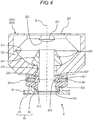
- Fig. 4 is a cross-sectional view illustrating a configuration example of a Cassegrain reflector retention mechanism 6 retaining the lower Cassegrain reflector 200B.
- This Cassegrain reflector retention mechanism 6 includes a retainer 61 which retains the lower Cassegrain reflector 200B.
- the retainer 61 retains the lower Cassegrain reflector 200B from below in a posture in which the secondary mirror 202 is located above the primary mirror 201.
- a cylindrical member 204 is attached to the opening 212 near the primary mirror 201 in the lower Cassegrain reflector 200B.
- the cylindrical member 204 extends in the axial line L and is fixed while being inserted through the opening 212.
- An upper end of the cylindrical member 204 is formed so that an outer circumferential surface thereof becomes a conical surface 241.
- This conical surface 241 is located between the primary mirror 201 and the secondary mirror 202 inside the lower Cassegrain reflector 200B. Accordingly, unnecessary multiple reflected light and scattered light can be cut.
- the threaded part 242 is formed as a compatible screw mount called an RMS mount (JIS standard M20. 32 (P0.706)). This threaded part 242 is threaded into a cylindrical nut part 62. Since the nut part 62 is strongly fastened to the threaded part 242, the nut part cannot be easily rotated.
- the attachment member 63 is attached to the outside of the nut part 62 in the radial direction.
- the attachment member 63 is a cylindrical member and an inner surface thereof is provided with a first inner circumferential surface 631 having an inner diameter larger than an outer diameter of the nut part 62 and a second inner circumferential surface 632 having an inner diameter smaller than the outer diameter of the nut part 62.
- the first inner circumferential surface 631 and the second inner circumferential surface 632 are connected to each other by an annular stepped surface 633.
- the nut part 62 is disposed at the inside of the first inner circumferential surface 631 inside the attachment member 63 and a lower end surface thereof comes into contact with the stepped surface 633. Accordingly, the nut part 62 is rotatable on the stepped surface 633 inside the attachment member 63. Thus, the lower Cassegrain reflector 200B is rotatable about the axial line L with respect to the attachment member 63 along with the nut part 62.
- a plurality of fixing nuts 64 are attached to an upper end of the attachment member 63 so as to penetrate the first inner circumferential surface 631.
- a protrusion amount from the first inner circumferential surface 631 is changed.
- the outer circumferential surface of the nut part 62 is provided with a tapered surface 621 and the front end of each fixing nut 64 is threaded into the tapered surface 621 to be bitten therein. Accordingly, since each fixing nut 64 is strongly fixed to the nut part 62, it is possible to prevent the nut part 62 from rotating about the axial line L with respect to the attachment member 63.
- a lower end of the attachment member 63 is received inside a recessed part 611 formed on an upper surface of the retainer 61.
- a positioning protrusion 612 is formed to protrude into the recessed part 611 of the retainer 61 and the rotation of the attachment member 63 about the axial line L on the retainer 61 can be prevented when the positioning protrusion 612 is locked to the lower end of the attachment member 63.
- the lower Cassegrain reflector 200B is retained on the retainer 61 along with the nut part 62 and the attachment member 63 and the lower Cassegrain reflector 200B can be rotated about the axial line L along with the nut part 62 while each fixing nut 64 is not fixed to the nut part 62.
- a plurality of supporting rods 232 (see Fig. 2 ) provided in the lower Cassegrain reflector 200B also rotate about the axial line L.
- the nut part 62 and the attachment member 63 constitute a rotation adjustment mechanism 60 which adjusts the rotational positions of the plurality of supporting rods 232 of the lower Cassegrain reflector 200B retained by the retainer 61 about the axial line L.
- the fixing nuts 64 constitute a fixing part which fixes the rotational positions of the plurality of supporting rods 232 of the lower Cassegrain reflector 200B and the fixing part is included in the rotation adjustment mechanism 60.
- the lower Cassegrain reflector 200B is attachable to or detachable from the retainer 61 along with the rotation adjustment mechanism 60. Then, in a state where the lower Cassegrain reflector 200B is attached to the retainer 61 along with the rotation adjustment mechanism 60, the positioning protrusion 612 serves as a positioning part for preventing the rotation of the lower Cassegrain reflector 200B along with the rotation adjustment mechanism 60.
- Figs. 5A to 5C are diagrams illustrating a case of adjusting the rotational positions of the plurality of supporting rods 232 using the rotation adjustment mechanism 60.
- Figs. 5A to 5C are diagrams in which the plurality of (for example, three) supporting rods 232 of the upper Cassegrain reflector 200A and the plurality of (for example, three) supporting rods 232 of the lower Cassegrain reflector 200B are viewed along the axial line L.
- each of the upper Cassegrain reflector 200A and the lower Cassegrain reflector 200B three supporting rods 232 are provided at the interval of 120° about the axial line L.
- six supporting rods 232 are located on the optical path so as not to overlap one another as illustrated in Fig. 5A when these supporting rods 232 are viewed along the axial line L.
- the rotational position of the supporting rod 232 of the lower Cassegrain reflector 200B can approach the rotational position of the supporting rod 232 of the upper Cassegrain reflector 200A as illustrated in Fig. 5B .
- the rotational positions are adjusted so that the supporting rod 232 of the lower Cassegrain reflector 200B overlaps the supporting rod 232 of the upper Cassegrain reflector 200A as illustrated in Fig. 5C , the number of the supporting rods 232 located on the optical path can be suppressed as small as possible.
- Fig. 6 is a flowchart illustrating an example of a method for attaching the Cassegrain reflector 200 in the case of performing the transmission measurement. Since the pair of Cassegrain reflectors 200 (the upper Cassegrain reflector 200A and the lower Cassegrain reflector 200B) is necessary in the case of performing the transmission measurement, the pair of Cassegrain reflectors 200 is coaxially provided with the measurement position P (see Fig. 3 ) interposed therebetween (step S101: an attachment step).
- step S102 when the visible light is irradiated from the visible light source 3 to the measurement position P (step S102), an operator can see the plurality of supporting rods 232 on the optical path.
- an operator rotates the lower Cassegrain reflector 200B about the axial line L by the rotation adjustment mechanism 60 while seeing the plurality of supporting rods 232 by eyes or a camera (not illustrated) (step S103).
- step S103 an adjustment step
- step S104 the rotational positions are adjusted (step S103: an adjustment step) until the supporting rod 232 of the upper Cassegrain reflector 200A and the supporting rod 232 of the lower Cassegrain reflector 200B overlap each other when viewed along the axial line L (until Yes in step S104) .
- step S105 the rotational position of the lower Cassegrain reflector 200B is fixed when the fixing nuts 64 are threaded into the attachment member 63 (step S105) while the supporting rod 232 of the upper Cassegrain reflector 200A overlaps the supporting rod 232 of the lower Cassegrain reflector 200B as illustrated in Fig. 5C (Yes in step S104).
- a configuration of rotating the plurality of supporting rods 232 of the lower Cassegrain reflector 200B when the pair of Cassegrain reflectors 200 (the upper Cassegrain reflector 200A and the lower Cassegrain reflector 200B) is coaxially disposed has been described.
- the invention is not limited to such a configuration and the same configuration such as the rotation adjustment mechanism 60 and the retainer 61 can be also applied to the upper Cassegrain reflector 200A.
- the rotational position of only the upper Cassegrain reflector 200A may be adjusted or the rotational positions of both the upper Cassegrain reflector 200A and the lower Cassegrain reflector 200B may be adjusted.
- the invention can be also applied to a case where one Cassegrain reflector (the upper Cassegrain reflector 200A) is used as in the case of performing the reflection measurement.
- the upper Cassegrain reflector 200A may be attached to the microscope 100 by omitting the lower Cassegrain reflector 200B or both the upper Cassegrain reflector 200A and the lower Cassegrain reflector 200B may be attached to the microscope 100 so that only the upper Cassegrain reflector 200A is used for the reflection measurement.
- Fig. 7 is a flowchart illustrating an example of a method for attaching the Cassegrain reflector 200 in the case of performing the reflection measurement.
- the upper Cassegrain reflector 200A is installed to face the measurement position P (see Fig. 3 ) (step S201: an installation step).
- step S202 when the visible light is irradiated from the visible light source 3 to the measurement position P (step S202), an operator can see the plurality of supporting rods 232 on the optical path.
- the operator rotates the upper Cassegrain reflector 200A by the rotation adjustment mechanism 60 about the axial line L while seeing the plurality of supporting rods 232 by eyes or a camera (not illustrated) (step S203).
- step S203 an adjustment step
- the rotational positions are adjusted (step S203: an adjustment step) until the plurality of supporting rods 232 of the upper Cassegrain reflector 200A become line-symmetrical with respect to a boundary line between the first region R1 and the second region R2 of the secondary mirror 202 of the upper Cassegrain reflector 200A when viewed along the axial line L (until Yes in step S204) .
- the fixing nuts 64 are threaded into the attachment member 63 while the plurality of supporting rods 232 become line-symmetrical with respect to the boundary line (Yes in step S204)
- the rotational position of the upper Cassegrain reflector 200A is fixed (step S205) .
- the light incident to the Cassegrain reflector 200 is reflected by the first region R1 of the secondary mirror 202, is reflected by the primary mirror 201, and is emitted to the measurement position P from the side of the secondary mirror 202, and the light reflected from the sample at the measurement position P is reflected by the primary mirror 201 and is reflected by the second region R2 of the secondary mirror 202 to emit the light
- the plurality of supporting rods 232 of the Cassegrain reflector 200 (the upper Cassegrain reflector 200A) are rotated.
- the pair of Cassegrain reflectors 200 (the upper Cassegrain reflector 200A and the lower Cassegrain reflector 200B) is coaxially disposed and then the rotational position of the upper Cassegrain reflector 200A is first adjusted as illustrated in Fig. 7 . Subsequently, when the rotational position of the lower Cassegrain reflector 200B is adjusted as illustrated in Fig. 6 , a light shield state caused by the plurality of supporting rods 232 can be suppressed as small as possible in both the reflection measurement and the transmission measurement.
- the rotation adjustment mechanism 60 (the nut part 62 and the attachment member 63) is attached to the threaded part 242 of the cylindrical member 204 provided in the Cassegrain reflector 200 .
- the invention is not limited to such a configuration.
- the rotation adjustment mechanism 60 may be attached to a different part of the Cassegrain reflector 200 or a rotation adjustment mechanism capable of adjusting the rotational positions of the plurality of supporting rods 232 may be provided inside the Cassegrain reflector 200.
- the fixing part for fixing the rotational positions of the plurality of supporting rods 232 of the Cassegrain reflector 200 is not limited to the fixing nut 64 as in the above-described embodiment and the rotational position may be fixed by other structures.
- the Cassegrain reflector retention mechanism 6 according to the invention is not limited to the microscope 100 capable of performing both the reflection measurement and the transmission measurement as in the above-described embodiment and can be also applied to the microscope capable of performing only one of the reflection measurement and the transmission measurement.
Landscapes
- Physics & Mathematics (AREA)
- General Physics & Mathematics (AREA)
- Optics & Photonics (AREA)
- Chemical & Material Sciences (AREA)
- Analytical Chemistry (AREA)
- Investigating Or Analysing Materials By Optical Means (AREA)
- Mounting And Adjusting Of Optical Elements (AREA)
- Microscoopes, Condenser (AREA)
- Lenses (AREA)
Abstract
Description
- The present invention relates to a Cassegrain reflector retention mechanism for retaining a Cassegrain reflector including a primary mirror and a secondary mirror disposed coaxially with the primary mirror and laterally supported by a plurality of supporting rods, a microscope including the same, and a method for attaching a Cassegrain reflector.
- For example, in an infrared microscope, infrared light or visible light can be selectively irradiated to a sample. Since common optical components are used in at least a part of an optical system for irradiating the infrared light to the sample and an optical system for irradiating the visible light to the sample, the number of components is decreased (for example, see Patent Document 1 below).
- It is considered to use an objective lens (transmission element) used in a biological microscope as part of the optical system. However, since the objective lens is normally corrected for aberration in a visible region, there is a problem that the influence of chromatic aberration increases and the imaging performance deteriorates when the objective lens is used in an infrared region. Also, since absorption occurs in the infrared region due to a glass material of the lens, the transmittance is greatly decreased and the usable wavelength range is extremely limited.
- For such a reason, in a general infrared microscope, a reflection optical system in which light reflected by an optical member is irradiated to a sample is used instead of a transmission optical system in which light transmitted through an optical member is irradiated to a sample. In the case of using such a reflection optical system, a problem of chromatic aberration does not arise differently from the case of using the transmission optical system. Further, since the reflectance of not only the visible region but also the infrared region is high in an aluminum vapor deposition mirror usually used in the reflection optical system, it is possible to use the infrared microscope in a wide wavelength region from the visible region to the infrared region.
- As optical components included in the reflection optical system, for example, a Cassegrain reflector including a primary mirror and a secondary mirror which are coaxially disposed is used. The Cassegrain reflector is a so-called Schwarzschild reflection objective mirror and has an optical arrangement which is very similar to a Cassegrain astronomical telescope.
- Further, in the infrared microscope capable of performing the transmission measurement, Cassegrain reflectors having the same specifications (magnification, numeral aperture NA, etc.) as imaging objective mirrors are often used in combination as condenser mirrors for collecting infrared light and irradiating the light to a sample. In this case, for example, a pair of Cassegrain reflectors are disposed above and below the sample. The pair of Cassegrain reflectors includes a Cassegrain reflector (a lower Cassegrain reflector) which focuses the infrared light to the sample from below and a Cassegrain reflector (an upper Cassegrain reflector) which images transmitted light directed upward from the sample.
-
Fig. 1 is a schematic cross-sectional view illustrating an example of an internal configuration of a Cassegrainreflector 200. Further,Fig. 2 is a schematic plan view illustrating an example of an external configuration of the Cassegrainreflector 200.Fig. 2 is a diagram illustrating the Cassegrainreflector 200 when viewed from the direction of an arrow A inFig. 1 . - The Cassegrain
reflector 200 is provided with, for example, aprimary mirror 201 and asecondary mirror 202. Theprimary mirror 201 includes areflection surface 211 formed as a spherical concave surface. Meanwhile, thesecondary mirror 202 includes areflection surface 221 formed as a spherical convex surface. Thereflection surface 221 of thesecondary mirror 202 has a diameter smaller than thereflection surface 211 of theprimary mirror 201. - The
primary mirror 201 and thesecondary mirror 202 are retained by ahollow casing 203. Theprimary mirror 201 and thesecondary mirror 202 are attached to thecasing 203 so that the centers of thereflection surfaces reflection surface 221 of thesecondary mirror 202 faces thereflection surface 211 of theprimary mirror 201 while being separated therefrom. - A surface facing the
reflection surface 211 of theprimary mirror 201 in thecasing 203 is provided with, for example, acircular opening 231. As illustrated inFig. 2 , thesecondary mirror 202 is supported by a plurality of supportingrods 232, radially extending from the circumferential edge of theopening 231 toward the axial line L, from the lateral side (the outside in the radial direction) to be located at the center portion of theopening 231. Accordingly, the opening 231 is defined into a plurality of regions by the supportingrods 232 at the side of thesecondary mirror 202. - As illustrated in
Fig. 1 , theprimary mirror 201 is provided with an opening 212 on the axial line L. The infrared light or the visible light is incident from theopening 212, is reflected by thereflection surface 221 of thesecondary mirror 202, and is reflected by thereflection surface 211 of theprimary mirror 201. At this time, a part of the light reflected by thereflection surface 211 of theprimary mirror 201 is shielded by thesecondary mirror 202, but the other light is emitted from the side of thesecondary mirror 202 through theopening 231. The light emitted from the opening 231 is focused to a measurement position P at the outside of thecasing 203. - Patent Document 1:
JP-A-2013-190554 - As described above, in the Cassegrain
reflector 200, the light flux in the vicinity of the axial line L of the incident light flux is shielded (obscured) by thesecondary mirror 202. For that reason, the Cassegrainreflector 200 has a characteristic that the light amount loss is larger than the objective lens in which the incident light flux substantially becomes the emitted light flux from the viewpoint of the ratio (throughput) between the incident light amount and the emitted light amount. - The shielding ratio which is the optical design specification for the shielding of the Cassegrain
reflector 200 is calculated by using a maximum numerical aperture NAmax of theprimary mirror 201 and a numerical aperture NAmin shielded by thesecondary mirror 202. Specifically, the shielding ratio is expressed by NAmin/NAmax × 100 (%). When designing the Cassegrainreflector 200, the shielding ratio is designed to be as small as possible, but in the case of the large Cassegrainreflector 200, the shielding ratio exceeds 40%. Accordingly, it may be very disadvantageous in terms of throughput as compared with the objective lens. - Further, a part of the light emitted from the side of the
secondary mirror 202 through the opening 231 is shielded by the plurality of supportingrods 232 located inside the opening 231. In general, two to four supportingrods 232 are used, but since the total area shielding the light flux increases as the number of the supportingrods 232 increases and the thickness of the supportingrod 232 increases, a problem arises in that the influence of the light amount loss increases. - Particularly, since the pair of Cassegrain
reflectors 200 is disposed above and below the sample in the case of performing the transmission measurement by the infrared microscope, the light flux is shielded by the supportingrod 232 when the light flux passes through the Cassegrainreflectors 200. For that reason, when the light flux shielding positions in the Cassegrainreflectors 200 do not overlap, the influence of the light amount loss due to the supportingrods 232 is doubled as compared with the case of the reflection measurement performed by one Cassegrainreflector 200, thereby causing a decrease in throughput. - The invention has been made in view of the above-described circumstances and an object of the invention is to provide a Cassegrain reflector retention mechanism capable of suppressing a light shield state caused by a plurality of supporting rods supporting a secondary mirror as small as possible, a microscope including the same, and a method for attaching a Cassegrain reflector.
-
- (1) A Cassegrain reflector retention mechanism according to the invention is a Cassegrain reflector retention mechanism for retaining a Cassegrain reflector that includes a primary mirror and a secondary mirror disposed coaxially with the primary mirror and laterally supported by a plurality of supporting rods and is used to reflect light incident from an opening formed on an axial line of the primary mirror by the secondary mirror, reflect the light by the primary mirror, and emit the light to a measurement position from a side of the secondary mirror. The Cassegrain reflector retention mechanism includes: a retainer that retains the Cassegrain reflector; and a rotation adjustment mechanism that adjusts rotational positions of the plurality of supporting rods of the Cassegrain reflector retained by the retainer about the axial line.
According to such a configuration, the rotational positions of the plurality of supporting rods supporting the secondary mirror with respect to the axial line can be adjusted by the rotation adjustment mechanism. Thus, when the rotational positions are appropriately adjusted, a light shield state caused by the plurality of supporting rods can be suppressed as small as possible.
For example, in the case of a configuration in which a pair of Cassegrain reflectors are coaxially disposed and light emitted from one Cassegrain reflector is incident to the other Cassegrain reflector as in the case of the transmission measurement, the plurality of supporting rods of at least one of the pair of Cassegrain reflectors are rotated. At this time, when the rotational positions are adjusted so that the plurality of supporting rods of the pair of Cassegrain reflectors overlap one another when viewed along the axial line, a light shield state caused by the plurality of supporting rods can be suppressed as small as possible.
Further, in the case of a configuration in which one Cassegrain reflector is used, light incident to the Cassegrain reflector is reflected by the first region of the secondary mirror, is reflected by the primary mirror, and is emitted to the measurement position from the side of the secondary mirror and light reflected from the sample at the measurement position is reflected by the primary mirror and is reflected by the second region of the secondary mirror to emit the light as in the case of the reflection measurement, the plurality of supporting rods of the Cassegrain reflector are rotated. At this time, when the rotational positions are adjusted so that the plurality of supporting rods become line-symmetrical when viewed along the axial line with respect to the boundary line between the first region and the second region of the secondary mirror, a light shield state caused by the plurality of supporting rods can be suppressed as small as possible. - (2) The rotation adjustment mechanism may include a fixing part that fixes the rotational positions of the plurality of supporting rods of the Cassegrain reflector.
According to such a configuration, the rotational positions of the plurality of supporting rods can be fixed by the fixing part after the rotational positions of the plurality of supporting rods are adjusted by the rotation adjustment mechanism with respect to the axial line. Accordingly, since a deviation of the rotational positions of the plurality of supporting rods can be prevented, a light shield state caused by the plurality of supporting rods can be reliably suppressed as small as possible. - (3) The Cassegrain reflector may be attachable to or detachable from the retainer along with the rotation adjustment mechanism.
According to such a configuration, an arbitrary Cassegrain reflector among the Cassegrain reflectors can be selectively attached to the retainer. At this time, since the Cassegrain reflector can be attached or detached along with the rotation adjustment mechanism, the rotational positions of the plurality of supporting rods adjusted once by the relation with the Cassegrain reflectors can be maintained. - (4) The retainer may include a positioning part that prevents the Cassegrain reflector from rotating along with the rotation adjustment mechanism.
According to such a configuration, since the rotational positions of the Cassegrain reflector and the rotation adjustment mechanism are determined by the positioning part, the rotational positions can be uniformly maintained even when the Cassegrain reflector and the rotation adjustment mechanism are attached to or detached from the retainer. Thus, when the rotational positions of the plurality of supporting rods are adjusted once by the relation with the Cassegrain reflector, there is no need to adjust the rotational positions even when the Cassegrain reflector is attached to or detached from the retainer along with the rotation adjustment mechanism later. - (5) A microscope according to the invention includes: the Cassegrain reflector retention mechanism; a Cassegrain reflector that is retained by the Cassegrain reflector retention mechanism; a light source that irradiates light to a sample through the Cassegrain reflector; and a detector that receives reflected light or transmitted light from a sample at the measurement position.
- (6) A method for attaching a Cassegrain reflector according to the invention includes: an installation step of coaxially installing a pair of the Cassegrain reflectors with the measurement position interposed therebetween; and an adjustment step of adjusting rotational positions so that the plurality of supporting rods of the pair of Cassegrain reflectors overlap each other when viewed along the axial line by rotating the plurality of supporting rods of at least one of the pair of Cassegrain reflectors about the axial line.
- (7) Another method for attaching a Cassegrain reflector according to the invention includes: an installation step of installing the Cassegrain reflector to face the measurement position; and an adjustment step of adjusting rotational positions so that the plurality of supporting rods become line-symmetrical when viewed along the axial line with respect to a boundary line between the first region and the second region of the secondary mirror by rotating the plurality of supporting rods of the Cassegrain reflector about the axial line.
- According to the invention, since the rotational positions of the plurality of supporting rods supporting the secondary mirror about the axial line can be adjusted by the rotation adjustment mechanism, a light shield state caused by the plurality of supporting rods can be suppressed as small as possible when the rotational positions are appropriately adjusted.
-
-
Fig. 1 is a schematic cross-sectional view illustrating an example of an internal configuration of a Cassegrain reflector. -
Fig. 2 is a schematic plan view illustrating an example of an external configuration of the Cassegrain reflector. -
Fig. 3 is a schematic diagram illustrating a configuration example of a microscope according to an embodiment of the invention. -
Fig. 4 is a cross-sectional view illustrating a configuration example of a Cassegrain reflector retention mechanism that retains a lower Cassegrain reflector. -
Fig. 5A is a diagram illustrating a case of adjusting rotational positions of a plurality of supporting rods using a rotation adjustment mechanism. -
Fig. 5B is a diagram illustrating the case of adjusting the rotational positions of the plurality of supporting rods using the rotation adjustment mechanism. -
Fig. 5C is a diagram illustrating the case of adjusting the rotational positions of the plurality of supporting rods using the rotation adjustment mechanism. -
Fig. 6 is a flowchart illustrating an example of a method for attaching a Cassegrain reflector in the case of performing transmission measurement. -
Fig. 7 is a flowchart illustrating an example of a method for attaching a Cassegrain reflector in the case of performing reflection measurement. -
Fig. 3 is a schematic diagram illustrating a configuration example of amicroscope 100 according to an embodiment of the invention. Thismicroscope 100 is, for example, an infrared microscope capable of selectively irradiating infrared light or visible light to a sample. Themicroscope 100 is provided with a sample stage 1, an infraredlight source 2, a visiblelight source 3, adetector 4, and acamera 5 other than aCassegrain reflector 200 illustrated inFigs. 1 and2 . - A sample which is an analysis target is placed on the sample stage 1. The sample stage 1 is configured to be movable in, for example, a horizontal direction (an XY direction) and a vertical direction (a Z direction). In this embodiment, a pair of the
Cassegrain reflectors 200 is installed at the upper and lower sides with the sample stage 1 interposed therebetween. - Although the Cassegrain reflector 200 (an
upper Cassegrain reflector 200A) installed above the sample stage 1 and the Cassegrain reflector 200 (alower Cassegrain reflector 200B) installed below the sample stage 1 respectively have the same configuration, the installation directions are different from each other. Specifically, theupper Cassegrain reflector 200A is disposed so that asecondary mirror 202 is located below aprimary mirror 201 and thelower Cassegrain reflector 200B is disposed so that asecondary mirror 202 is located above aprimary mirror 201. Theupper Cassegrain reflector 200A and thelower Cassegrain reflector 200B are coaxially disposed so that their axial lines L respectively extend in the vertical direction. - The infrared
light source 2 emits infrared light and irradiates the infrared light onto the sample stage 1 through theCassegrain reflector 200. In the case of the reflection measurement, the light emitted from the infraredlight source 2 is sequentially reflected by reflection mirrors 21, 22, and 23, is sequentially reflected by aconcave mirror 24 and ahalf mirror 26, and is introduced into theupper Cassegrain reflector 200A from above. Meanwhile, in the case of the transmission measurement, when the angle of thereflection mirror 23 is changed, the light emitted from the infraredlight source 2 is sequentially reflected by the reflection mirrors 21, 22, and 23, is sequentially reflected by aconcave mirror 25 and areflection mirror 27, and is introduced into thelower Cassegrain reflector 200B from below. - The visible
light source 3 emits visible light so that the visible light is irradiated onto the sample stage 1 through theCassegrain reflector 200. The visible light emitted from the visiblelight source 3 is guided to theCassegrain reflector 200 while passing through an optical path which is mostly in common with an optical path of the infrared light. Thereflection mirror 22 is configured to advance or retreat with respect to the optical paths of the infrared light and the visible light and thereflection mirror 22 retreats from the optical path when the visible light is emitted from the visiblelight source 3. Similarly to the infrared light emitted from the infraredlight source 2, the visible light emitted from the visiblelight source 3 can be introduced into theupper Cassegrain reflector 200A from above through thereflection mirror 23, theconcave mirror 24, and thehalf mirror 26 and can be introduced into thelower Cassegrain reflector 200B from below through thereflection mirror 23, theconcave mirror 25, and thereflection mirror 27. - At the time of performing the reflection measurement, the infrared light introduced from an
opening 212 near theprimary mirror 201 inside theupper Cassegrain reflector 200A is sequentially reflected by thesecondary mirror 202 and theprimary mirror 201 and is focused to a measurement position P on the sample stage 1 from above through anopening 231 near thesecondary mirror 202. At this time, the light being incident to the Cassegrain reflector 200 (theupper Cassegrain reflector 200A) is reflected by a first region R1 of thesecondary mirror 202, is reflected by theprimary mirror 201, and is emitted to the measurement position P from the side of the secondary mirror 202 (seeFig. 1 ). - The light reflected from the sample placed on the measurement position P is incident into the
upper Cassegrain reflector 200A again through theopening 231 near thesecondary mirror 202, is sequentially reflected by theprimary mirror 201 and thesecondary mirror 202, and is emitted from theopening 212 near theprimary mirror 201. At this time, the light reflected from the sample at the measurement position P is reflected by theprimary mirror 201 and is reflected by a second region R2 of thesecondary mirror 202 to emit the light (seeFig. 1 ). As illustrated inFig. 1 , the first region R1 and the second region R2 are located so as not to overlap each other with the axial line L interposed therebetween. - The light emitted from the
opening 212 of theupper Cassegrain reflector 200A is transmitted through thehalf mirror 26. Then, the light transmitted through thehalf mirror 26 passes through aslit 41, is sequentially reflected by reflection mirrors 42 and 43 and acollector mirror 44, and is received by thedetector 4. Accordingly, since a detection signal is output from thedetector 4, the reflection measurement of the sample can be performed on the basis of the detection signal. - Meanwhile, in the case of performing the transmission measurement, the infrared light introduced into the
lower Cassegrain reflector 200B from theopening 212 near theprimary mirror 201 is sequentially reflected by thesecondary mirror 202 and theprimary mirror 201 and is focused to the measurement position P on the sample stage 1 from below through theopening 231 near thesecondary mirror 202. At this time, the light being incident to the Cassegrain reflector 200 (thelower Cassegrain reflector 200B) is reflected by the entire region (the first region R1 and the second region R2) of thesecondary mirror 202, is reflected by theprimary mirror 201, and is emitted to the measurement position P from the side of the secondary mirror 202 (seeFig. 1 ). Then, the light transmitted through the sample placed on the measurement position P is incident into theupper Cassegrain reflector 200A through theopening 231 near thesecondary mirror 202. - The light being incident into the
upper Cassegrain reflector 200A is sequentially reflected by theprimary mirror 201 and thesecondary mirror 202 and is emitted from theopening 212 near theprimary mirror 201. At this time, the light reflected by theprimary mirror 201 is reflected by the entire region (the first region R1 and the second region R2) of thesecondary mirror 202 and is emitted from theopening 212 near the primary mirror 201 (seeFig. 1 ). - The light emitted from the
opening 212 of theupper Cassegrain reflector 200A is transmitted through thehalf mirror 26. Then, the light transmitted through thehalf mirror 26 passes through theslit 41, is sequentially reflected by the reflection mirrors 42 and 43 and thecollector mirror 44, and is received by thedetector 4. Accordingly, since a detection signal is output from thedetector 4, the transmission measurement of the sample can be performed on the basis of the detection signal. - When the visible light is irradiated from the visible
light source 3 to the measurement position P on the sample stage 1, the visible light from the measurement position P is incident into theupper Cassegrain reflector 200A through theopening 231 near thesecondary mirror 202. Then, the visible light being incident into theupper Cassegrain reflector 200A is sequentially reflected by theprimary mirror 201 and thesecondary mirror 202, is emitted from theopening 212 near theprimary mirror 201, and is transmitted through thehalf mirror 26. - The
reflection mirror 42 is configured to advance or retreat with respect to the optical paths of the infrared light and the visible light and thereflection mirror 42 retreats from the optical path when the visible light is emitted from the visiblelight source 3. The visible light transmitted through thehalf mirror 26 passes through theslit 41, is focused by alens 51, and is incident to thecamera 5. Accordingly, an image illuminated by the visible light can be photographed by thecamera 5 and the image can be checked. -
Fig. 4 is a cross-sectional view illustrating a configuration example of a Cassegrainreflector retention mechanism 6 retaining thelower Cassegrain reflector 200B. This Cassegrainreflector retention mechanism 6 includes aretainer 61 which retains thelower Cassegrain reflector 200B. Theretainer 61 retains thelower Cassegrain reflector 200B from below in a posture in which thesecondary mirror 202 is located above theprimary mirror 201. - In this example, a cylindrical member 204 is attached to the
opening 212 near theprimary mirror 201 in thelower Cassegrain reflector 200B. The cylindrical member 204 extends in the axial line L and is fixed while being inserted through theopening 212. An upper end of the cylindrical member 204 is formed so that an outer circumferential surface thereof becomes aconical surface 241. Thisconical surface 241 is located between theprimary mirror 201 and thesecondary mirror 202 inside thelower Cassegrain reflector 200B. Accordingly, unnecessary multiple reflected light and scattered light can be cut. - A lower end of the cylindrical member 204 protrudes toward the outside of the
lower Cassegrain reflector 200B and an outer circumferential surface thereof is provided with a threadedpart 242. The threadedpart 242 is formed as a compatible screw mount called an RMS mount (JIS standard M20. 32 (P0.706)). This threadedpart 242 is threaded into acylindrical nut part 62. Since thenut part 62 is strongly fastened to the threadedpart 242, the nut part cannot be easily rotated. - An
attachment member 63 is attached to the outside of thenut part 62 in the radial direction. Theattachment member 63 is a cylindrical member and an inner surface thereof is provided with a first innercircumferential surface 631 having an inner diameter larger than an outer diameter of thenut part 62 and a second innercircumferential surface 632 having an inner diameter smaller than the outer diameter of thenut part 62. The first innercircumferential surface 631 and the second innercircumferential surface 632 are connected to each other by an annular steppedsurface 633. - The
nut part 62 is disposed at the inside of the first innercircumferential surface 631 inside theattachment member 63 and a lower end surface thereof comes into contact with the steppedsurface 633. Accordingly, thenut part 62 is rotatable on the steppedsurface 633 inside theattachment member 63. Thus, thelower Cassegrain reflector 200B is rotatable about the axial line L with respect to theattachment member 63 along with thenut part 62. - A plurality of fixing
nuts 64 are attached to an upper end of theattachment member 63 so as to penetrate the first innercircumferential surface 631. When the threaded amount of these fixingnuts 64 with respect to theattachment member 63 is adjusted, a protrusion amount from the first innercircumferential surface 631 is changed. Thus, when each fixingnut 64 is threaded into theattachment member 63, a front end of each fixingnut 64 comes into contact with an outer circumferential surface of thenut part 62 so that the rotational position of thenut part 62 with respect to the axial line L can be fixed. - The outer circumferential surface of the
nut part 62 is provided with atapered surface 621 and the front end of each fixingnut 64 is threaded into thetapered surface 621 to be bitten therein. Accordingly, since each fixingnut 64 is strongly fixed to thenut part 62, it is possible to prevent thenut part 62 from rotating about the axial line L with respect to theattachment member 63. - A lower end of the
attachment member 63 is received inside a recessedpart 611 formed on an upper surface of theretainer 61. Apositioning protrusion 612 is formed to protrude into the recessedpart 611 of theretainer 61 and the rotation of theattachment member 63 about the axial line L on theretainer 61 can be prevented when thepositioning protrusion 612 is locked to the lower end of theattachment member 63. - In this way, the
lower Cassegrain reflector 200B is retained on theretainer 61 along with thenut part 62 and theattachment member 63 and thelower Cassegrain reflector 200B can be rotated about the axial line L along with thenut part 62 while each fixingnut 64 is not fixed to thenut part 62. When thelower Cassegrain reflector 200B is rotated about the axial line L, a plurality of supporting rods 232 (seeFig. 2 ) provided in thelower Cassegrain reflector 200B also rotate about the axial line L. - Thus, the
nut part 62 and theattachment member 63 constitute arotation adjustment mechanism 60 which adjusts the rotational positions of the plurality of supportingrods 232 of thelower Cassegrain reflector 200B retained by theretainer 61 about the axial line L. Further, the fixingnuts 64 constitute a fixing part which fixes the rotational positions of the plurality of supportingrods 232 of thelower Cassegrain reflector 200B and the fixing part is included in therotation adjustment mechanism 60. - The
lower Cassegrain reflector 200B is attachable to or detachable from theretainer 61 along with therotation adjustment mechanism 60. Then, in a state where thelower Cassegrain reflector 200B is attached to theretainer 61 along with therotation adjustment mechanism 60, thepositioning protrusion 612 serves as a positioning part for preventing the rotation of thelower Cassegrain reflector 200B along with therotation adjustment mechanism 60. -
Figs. 5A to 5C are diagrams illustrating a case of adjusting the rotational positions of the plurality of supportingrods 232 using therotation adjustment mechanism 60.Figs. 5A to 5C are diagrams in which the plurality of (for example, three) supportingrods 232 of theupper Cassegrain reflector 200A and the plurality of (for example, three) supportingrods 232 of thelower Cassegrain reflector 200B are viewed along the axial line L. - In this embodiment, in each of the
upper Cassegrain reflector 200A and thelower Cassegrain reflector 200B, three supportingrods 232 are provided at the interval of 120° about the axial line L. In this case, when the rotational position of the supportingrod 232 of theupper Cassegrain reflector 200A and the rotational position of the supportingrod 232 of thelower Cassegrain reflector 200B are deviated from each other by 180°, six supportingrods 232 are located on the optical path so as not to overlap one another as illustrated inFig. 5A when these supportingrods 232 are viewed along the axial line L. - In this case, when the
lower Cassegrain reflector 200B is rotated by therotation adjustment mechanism 60 with respect to theretainer 61, the rotational position of the supportingrod 232 of thelower Cassegrain reflector 200B can approach the rotational position of the supportingrod 232 of theupper Cassegrain reflector 200A as illustrated inFig. 5B . Then, when the rotational positions are adjusted so that the supportingrod 232 of thelower Cassegrain reflector 200B overlaps the supportingrod 232 of theupper Cassegrain reflector 200A as illustrated inFig. 5C , the number of the supportingrods 232 located on the optical path can be suppressed as small as possible. -
Fig. 6 is a flowchart illustrating an example of a method for attaching theCassegrain reflector 200 in the case of performing the transmission measurement. Since the pair of Cassegrain reflectors 200 (theupper Cassegrain reflector 200A and thelower Cassegrain reflector 200B) is necessary in the case of performing the transmission measurement, the pair ofCassegrain reflectors 200 is coaxially provided with the measurement position P (seeFig. 3 ) interposed therebetween (step S101: an attachment step). - Subsequently, when the visible light is irradiated from the visible
light source 3 to the measurement position P (step S102), an operator can see the plurality of supportingrods 232 on the optical path. In this state, an operator rotates thelower Cassegrain reflector 200B about the axial line L by therotation adjustment mechanism 60 while seeing the plurality of supportingrods 232 by eyes or a camera (not illustrated) (step S103). - At this time, the rotational positions are adjusted (step S103: an adjustment step) until the supporting
rod 232 of theupper Cassegrain reflector 200A and the supportingrod 232 of thelower Cassegrain reflector 200B overlap each other when viewed along the axial line L (until Yes in step S104) . Then, the rotational position of thelower Cassegrain reflector 200B is fixed when the fixingnuts 64 are threaded into the attachment member 63 (step S105) while the supportingrod 232 of theupper Cassegrain reflector 200A overlaps the supportingrod 232 of thelower Cassegrain reflector 200B as illustrated inFig. 5C (Yes in step S104). -
- (1) In this embodiment, the rotational positions of the plurality of supporting
rods 232 supporting thesecondary mirror 202 can be adjusted by therotation adjustment mechanism 60 with respect to the axial line L. Thus, when the rotational positions are appropriately adjusted, a light shield state caused by the plurality of supportingrods 232 can be suppressed as small as possible.
As in the case of the transmission measurement illustrated inFig. 6 , in the case of a configuration in which the pair of Cassegrain reflectors 200 (theupper Cassegrain reflector 200A and thelower Cassegrain reflector 200B) is coaxially disposed and the light emitted from thelower Cassegrain reflector 200B is incident to theupper Cassegrain reflector 200A, for example, the plurality of supportingrods 232 of the lower Cassegrain reflector are rotated. At this time, when the rotational positions are adjusted so that the supportingrod 232 of theupper Cassegrain reflector 200A and the supportingrod 232 of thelower Cassegrain reflector 200B overlap each other when viewed along the axial line L, a light shield state caused by the plurality of supportingrods 232 can be suppressed as small as possible. - (2) In this embodiment, the rotational positions of the plurality of supporting
rods 232 can be fixed by the fixingnuts 64 after the rotational positions of the plurality of supportingrods 232 with respect to the axial line L are adjusted by therotation adjustment mechanism 60. Accordingly, since a deviation of the rotational positions of the plurality of supportingrods 232 can be prevented, a light shield state caused by the plurality of supportingrods 232 can be suppressed as small as possible. - (3) In this embodiment, since the Cassegrain reflector 200 (the
lower Cassegrain reflector 200B) can be attached to or detached from theretainer 61, anarbitrary Cassegrain reflector 200 among the plural kinds ofCassegrain reflectors 200 can be selectively attached to theretainer 61. At this time, since theCassegrain reflector 200 can be attached or detached along with therotation adjustment mechanism 60, the rotational positions of the plurality of supportingrods 232 adjusted once by the relation with theCassegrain reflectors 200 can be maintained. - (4) In this embodiment, since the rotational positions of the Cassegrain reflector 200 (the
lower Cassegrain reflector 200B) and therotation adjustment mechanism 60 are determined by thepositioning protrusion 612, the rotational positions can be uniformly maintained even when theCassegrain reflector 200 and therotation adjustment mechanism 60 are attached to or detached from theretainer 61. Thus, when the rotational positions of the plurality of supportingrods 232 are adjusted once by the relation with theCassegrain reflector 200, there is no need to adjust the rotational position again even when theCassegrain reflector 200 is attached to or detached from theretainer 61 along with therotation adjustment mechanism 60 later. - In the above-described embodiment, a configuration of rotating the plurality of supporting
rods 232 of thelower Cassegrain reflector 200B when the pair of Cassegrain reflectors 200 (theupper Cassegrain reflector 200A and thelower Cassegrain reflector 200B) is coaxially disposed has been described. However, the invention is not limited to such a configuration and the same configuration such as therotation adjustment mechanism 60 and theretainer 61 can be also applied to theupper Cassegrain reflector 200A. In this case, the rotational position of only theupper Cassegrain reflector 200A may be adjusted or the rotational positions of both theupper Cassegrain reflector 200A and thelower Cassegrain reflector 200B may be adjusted. - In the above-described embodiment, a case of performing the transmission measurement has been described, but the invention can be also applied to a case where one Cassegrain reflector (the
upper Cassegrain reflector 200A) is used as in the case of performing the reflection measurement. In this case, only theupper Cassegrain reflector 200A may be attached to themicroscope 100 by omitting thelower Cassegrain reflector 200B or both theupper Cassegrain reflector 200A and thelower Cassegrain reflector 200B may be attached to themicroscope 100 so that only theupper Cassegrain reflector 200A is used for the reflection measurement. -
Fig. 7 is a flowchart illustrating an example of a method for attaching theCassegrain reflector 200 in the case of performing the reflection measurement. In the case of performing the reflection measurement, for example, theupper Cassegrain reflector 200A is installed to face the measurement position P (seeFig. 3 ) (step S201: an installation step). - Subsequently, when the visible light is irradiated from the visible
light source 3 to the measurement position P (step S202), an operator can see the plurality of supportingrods 232 on the optical path. In this state, the operator rotates theupper Cassegrain reflector 200A by therotation adjustment mechanism 60 about the axial line L while seeing the plurality of supportingrods 232 by eyes or a camera (not illustrated) (step S203). - At this time, the rotational positions are adjusted (step S203: an adjustment step) until the plurality of supporting
rods 232 of theupper Cassegrain reflector 200A become line-symmetrical with respect to a boundary line between the first region R1 and the second region R2 of thesecondary mirror 202 of theupper Cassegrain reflector 200A when viewed along the axial line L (until Yes in step S204) . Then, when the fixingnuts 64 are threaded into theattachment member 63 while the plurality of supportingrods 232 become line-symmetrical with respect to the boundary line (Yes in step S204), the rotational position of theupper Cassegrain reflector 200A is fixed (step S205) . - As in the case of the reflection measurement illustrated in
Fig. 7 , in the case of a configuration in which one Cassegrain reflector 200 (theupper Cassegrain reflector 200A) is used, the light incident to theCassegrain reflector 200 is reflected by the first region R1 of thesecondary mirror 202, is reflected by theprimary mirror 201, and is emitted to the measurement position P from the side of thesecondary mirror 202, and the light reflected from the sample at the measurement position P is reflected by theprimary mirror 201 and is reflected by the second region R2 of thesecondary mirror 202 to emit the light, the plurality of supportingrods 232 of the Cassegrain reflector 200 (theupper Cassegrain reflector 200A) are rotated. At this time, when the rotational positions are adjusted so that the plurality of supportingrods 232 become line-symmetrical with respect to the boundary line between the first region R1 and the second region R2 of thesecondary mirror 202 when viewed along the axial line L, a light shield state caused by the plurality of supportingrods 232 can be suppressed as small as possible. - As in the
microscope 100 illustrated inFig. 3 , in the case of themicroscope 100 capable of performing both the reflection measurement and the transmission measurement, the pair of Cassegrain reflectors 200 (theupper Cassegrain reflector 200A and thelower Cassegrain reflector 200B) is coaxially disposed and then the rotational position of theupper Cassegrain reflector 200A is first adjusted as illustrated inFig. 7 . Subsequently, when the rotational position of thelower Cassegrain reflector 200B is adjusted as illustrated inFig. 6 , a light shield state caused by the plurality of supportingrods 232 can be suppressed as small as possible in both the reflection measurement and the transmission measurement. - In the above-described embodiment, a configuration in which the rotation adjustment mechanism 60 (the
nut part 62 and the attachment member 63) is attached to the threadedpart 242 of the cylindrical member 204 provided in theCassegrain reflector 200 has been described. However, the invention is not limited to such a configuration. For example, therotation adjustment mechanism 60 may be attached to a different part of theCassegrain reflector 200 or a rotation adjustment mechanism capable of adjusting the rotational positions of the plurality of supportingrods 232 may be provided inside theCassegrain reflector 200. - The fixing part for fixing the rotational positions of the plurality of supporting
rods 232 of theCassegrain reflector 200 is not limited to the fixingnut 64 as in the above-described embodiment and the rotational position may be fixed by other structures. - The Cassegrain
reflector retention mechanism 6 according to the invention is not limited to themicroscope 100 capable of performing both the reflection measurement and the transmission measurement as in the above-described embodiment and can be also applied to the microscope capable of performing only one of the reflection measurement and the transmission measurement. -
- 1
- Sample stage
- 2
- Infrared light source
- 3
- Visible light source
- 4
- Detector
- 5
- Camera
- 6
- Cassegrain reflector retention mechanism
- 60
- Rotation adjustment mechanism
- 61
- Retainer
- 62
- Nut part
- 63
- Attachment member
- 64
- Fixing nut
- 100
- Microscope
- 200
- Cassegrain reflector
- 200A
- Upper Cassegrain reflector
- 200B
- Lower Cassegrain reflector
- 201
- Primary mirror
- 202
- Secondary mirror
- 203
- Casing
- 204
- Cylindrical member
- 211
- Reflection surface
- 212
- Opening
- 221
- Reflection surface
- 231
- Opening
- 232
- Supporting rod
- 241
- Conical surface
- 242
- Threaded part
- 611
- Recessed part
- 612
- Positioning protrusion
- 621
- Tapered surface
- 631
- Inner circumferential surface
- 632
- Inner circumferential surface
- 633
- Stepped surface
Claims (7)
- A Cassegrain reflector retention mechanism for retaining a Cassegrain reflector that includes a primary mirror and a secondary mirror disposed coaxially with the primary mirror and laterally supported by a plurality of supporting rods and is used to reflect light incident from an opening formed on an axial line of the primary mirror by the secondary mirror, reflect the light by the primary mirror, and emit the light to a measurement position from a side of the secondary mirror, comprising:a retainer that retains the Cassegrain reflector; anda rotation adjustment mechanism that adjusts rotational positions of the plurality of supporting rods of the Cassegrain reflector retained by the retainer about the axial line.
- The Cassegrain reflector retention mechanism according to claim 1,
wherein the rotation adjustment mechanism includes a fixing part that fixes the rotational positions of the plurality of supporting rods of the Cassegrain reflector. - The Cassegrain reflector retention mechanism according to claim 1 or 2,
wherein the Cassegrain reflector is attachable to or detachable from the retainer along with the rotation adjustment mechanism. - The Cassegrain reflector retention mechanism according to claim 3,
wherein the retainer includes a positioning part that prevents the Cassegrain reflector from rotating along with the rotation adjustment mechanism. - A microscope comprising:the Cassegrain reflector retention mechanism according to any one of claims 1 to 4;a Cassegrain reflector that is retained by the Cassegrain reflector retention mechanism;a light source that irradiates light to a sample through the Cassegrain reflector; anda detector that receives reflected light or transmitted light from a sample at the measurement position.
- A method for attaching a Cassegrain reflector that includes a primary mirror and a secondary mirror disposed coaxially with the primary mirror and laterally supported by a plurality of supporting rods and is used to reflect light incident from an opening formed on an axial line of the primary mirror by the secondary mirror, reflect the light by the primary mirror, and emit the light to a measurement position from a side of the secondary mirror, comprising:an installation step of coaxially installing a pair of the Cassegrain reflectors with the measurement position interposed therebetween; andan adjustment step of adjusting rotational positions so that the plurality of supporting rods of the pair of Cassegrain reflectors overlap each other when viewed along the axial line by rotating the plurality of supporting rods of at least one of the pair of Cassegrain reflectors about the axial line.
- A method for attaching a Cassegrain reflector that includes a primary mirror and a secondary mirror disposed coaxially with the primary mirror and laterally supported by a plurality of supporting rods, is used to reflect light incident from an opening formed on an axial line of the primary mirror by a first region of the secondary mirror, reflect the light by the primary mirror, and emit the light to a measurement position from a side of the secondary mirror, and is used to reflect light reflected from a sample at the measurement position by the primary mirror, reflect the light by a second region of the secondary mirror, and emit the light from the opening, comprising:an installation step of installing the Cassegrain reflector to face the measurement position; andan adjustment step of adjusting rotational positions so that the plurality of supporting rods become line-symmetrical when viewed along the axial line with respect to a boundary line between the first region and the second region of the secondary mirror by rotating the plurality of supporting rods of the Cassegrain reflector about the axial line.
Applications Claiming Priority (1)
| Application Number | Priority Date | Filing Date | Title |
|---|---|---|---|
| PCT/JP2015/066816 WO2016199262A1 (en) | 2015-06-11 | 2015-06-11 | Cassegrain reflector retention mechanism, microscope equipped with same, and method for attaching cassegrain reflector |
Publications (3)
| Publication Number | Publication Date |
|---|---|
| EP3309594A1 true EP3309594A1 (en) | 2018-04-18 |
| EP3309594A4 EP3309594A4 (en) | 2019-02-27 |
| EP3309594B1 EP3309594B1 (en) | 2024-07-24 |
Family
ID=57504710
Family Applications (1)
| Application Number | Title | Priority Date | Filing Date |
|---|---|---|---|
| EP15894947.9A Active EP3309594B1 (en) | 2015-06-11 | 2015-06-11 | Cassegrain reflector retention mechanism, microscope equipped with same, and method for attaching cassegrain reflector |
Country Status (4)
| Country | Link |
|---|---|
| US (1) | US10649190B2 (en) |
| EP (1) | EP3309594B1 (en) |
| JP (1) | JP6540799B2 (en) |
| WO (1) | WO2016199262A1 (en) |
Families Citing this family (13)
| Publication number | Priority date | Publication date | Assignee | Title |
|---|---|---|---|---|
| CN107037567B (en) * | 2017-05-19 | 2020-09-18 | 北京空间机电研究所 | A mirror support structure with three-point ball joint combined with radial cementation |
| KR20190052516A (en) * | 2017-11-08 | 2019-05-16 | 삼성전자주식회사 | Surface inspection apparatus |
| CN110531531B (en) * | 2019-09-27 | 2021-08-03 | 昆明北方红外技术股份有限公司 | Method for assembling and adjusting primary and secondary reflectors of Cassegrain optical system |
| CN112903608B (en) * | 2020-12-30 | 2023-07-25 | 安徽宝龙环保科技有限公司 | Multi-channel long-optical-path telescope system and application thereof |
| JP7720163B2 (en) * | 2021-04-30 | 2025-08-07 | 株式会社キーエンス | Analyzer |
| JP7717487B2 (en) * | 2021-04-30 | 2025-08-04 | 株式会社キーエンス | Analyzer |
| CN114089582A (en) * | 2021-11-16 | 2022-02-25 | Oppo广东移动通信有限公司 | Shading assembly and preparation method thereof, optical lens, camera and electronic equipment |
| CN115145001B (en) * | 2022-07-22 | 2023-05-16 | 中国科学院长春光学精密机械与物理研究所 | Secondary mirror support structure with preload |
| US12452502B2 (en) * | 2023-05-18 | 2025-10-21 | Bob Pilgrim | Dual-band panoramic camera system |
| KR102697241B1 (en) * | 2023-11-14 | 2024-08-23 | 대한민국(방위사업청장) | Optical module for electro-optics payload and electro-optics payload having the same |
| KR102697244B1 (en) * | 2023-11-14 | 2024-08-23 | 대한민국(방위사업청장) | Optical module for electro-optics payload and electro-optics payload having the same |
| KR102697245B1 (en) * | 2023-11-14 | 2024-08-22 | 대한민국(방위사업청장) | Electro-optics payload |
| WO2026048069A1 (en) * | 2024-09-02 | 2026-03-05 | 日本分光株式会社 | Detachable structure for microscope cassegrain mirror |
Family Cites Families (14)
| Publication number | Priority date | Publication date | Assignee | Title |
|---|---|---|---|---|
| GB695297A (en) * | 1950-10-23 | 1953-08-05 | Cooke Troughton & Simms Ltd | Improvements in microscope objectives |
| US5093580A (en) * | 1990-03-02 | 1992-03-03 | Spectra-Tech, Inc. | ATR objective and method for sample analyzation using an ATR crystal |
| US5019715A (en) * | 1990-03-02 | 1991-05-28 | Spectra-Tech, Inc. | Optical system and method for sample analyzation |
| JP3136576B2 (en) * | 1992-06-18 | 2001-02-19 | 株式会社島津製作所 | Microscopic total reflection absorption spectrum measurement device |
| JP3058000B2 (en) * | 1994-02-28 | 2000-07-04 | キヤノン株式会社 | Mirror optics |
| JPH11305204A (en) * | 1998-04-21 | 1999-11-05 | Matsushita Electric Ind Co Ltd | Display panel, method of manufacturing the same, and display device using the display panel |
| EP1184702B1 (en) * | 2000-08-29 | 2011-12-21 | PerkinElmer Singapore Pte. Ltd. | Infrared imaging microscope |
| JP2006047780A (en) * | 2004-08-05 | 2006-02-16 | Shimadzu Corp | Infrared microscope |
| JP2009210765A (en) * | 2008-03-04 | 2009-09-17 | Seiko Epson Corp | Projector |
| JP2009271482A (en) * | 2008-04-30 | 2009-11-19 | Sanryu:Kk | Multiple-image display method |
| KR101040981B1 (en) * | 2010-01-20 | 2011-06-16 | 한국기초과학지원연구원 | Tilting device for aligning precision optics |
| JP5539836B2 (en) * | 2010-09-30 | 2014-07-02 | 立川ブラインド工業株式会社 | Dimmable roll blind |
| US20120306998A1 (en) * | 2011-06-01 | 2012-12-06 | Merrill Ii Dennis E | Macro Area Camera for an Infrared (IR) Microscope |
| JP5867194B2 (en) * | 2012-03-13 | 2016-02-24 | 株式会社島津製作所 | microscope |
-
2015
- 2015-06-11 JP JP2017523041A patent/JP6540799B2/en active Active
- 2015-06-11 US US15/580,477 patent/US10649190B2/en active Active
- 2015-06-11 EP EP15894947.9A patent/EP3309594B1/en active Active
- 2015-06-11 WO PCT/JP2015/066816 patent/WO2016199262A1/en not_active Ceased
Also Published As
| Publication number | Publication date |
|---|---|
| EP3309594A4 (en) | 2019-02-27 |
| US20180143417A1 (en) | 2018-05-24 |
| JP6540799B2 (en) | 2019-07-10 |
| JPWO2016199262A1 (en) | 2017-11-09 |
| EP3309594B1 (en) | 2024-07-24 |
| WO2016199262A1 (en) | 2016-12-15 |
| US10649190B2 (en) | 2020-05-12 |
Similar Documents
| Publication | Publication Date | Title |
|---|---|---|
| EP3309594B1 (en) | Cassegrain reflector retention mechanism, microscope equipped with same, and method for attaching cassegrain reflector | |
| JP4937255B2 (en) | Beam delivery system for laser dark field illumination in catadioptric optics | |
| US20200241275A1 (en) | Optical device for microscopic observation | |
| CN109739013A (en) | Off-axis three reflecting optical system of big coke ratio wide visual field with real entrance pupil | |
| EP2881778B1 (en) | Scanning light microscope with focus adjustment | |
| JP6319462B2 (en) | Objective optical system for ATR measurement | |
| US10146037B2 (en) | Microscope | |
| WO2016047667A1 (en) | Solid immersion lens holder and image acquisition device | |
| EP2045646B1 (en) | Star sensor with a dual optical power lens to reduce stray light | |
| WO2021016445A1 (en) | On-axis four mirror anastigmat telescope | |
| CN109633882B (en) | Phase contrast microscope and debugging method thereof | |
| EP2856094A1 (en) | Optical imaging system that incorporates an uni-axial optical homogenizer | |
| US9857579B2 (en) | System for microscopic applications | |
| US20250102446A1 (en) | Optical systems and methods of providing a coupling mirror to an optical system | |
| US7388322B2 (en) | Illumination device for microscopes | |
| Brendel et al. | Balloon-borne FIREBall-2 ultraviolet spectrograph stray light control based on nonsequential reverse modeling of on-sky data | |
| US10620418B2 (en) | Optical pickup device | |
| Buchheister et al. | Objective With Supressed Single Reflexes | |
| WO1997024636A1 (en) | Grazing angle mirror objective with non-spherical mirrors | |
| CZ2006830A3 (en) | Segmented mirror for lidar | |
| GB2553400A (en) | Optronic Sensor Apparatus |
Legal Events
| Date | Code | Title | Description |
|---|---|---|---|
| STAA | Information on the status of an ep patent application or granted ep patent |
Free format text: STATUS: THE INTERNATIONAL PUBLICATION HAS BEEN MADE |
|
| PUAI | Public reference made under article 153(3) epc to a published international application that has entered the european phase |
Free format text: ORIGINAL CODE: 0009012 |
|
| STAA | Information on the status of an ep patent application or granted ep patent |
Free format text: STATUS: REQUEST FOR EXAMINATION WAS MADE |
|
| 17P | Request for examination filed |
Effective date: 20180104 |
|
| AK | Designated contracting states |
Kind code of ref document: A1 Designated state(s): AL AT BE BG CH CY CZ DE DK EE ES FI FR GB GR HR HU IE IS IT LI LT LU LV MC MK MT NL NO PL PT RO RS SE SI SK SM TR |
|
| AX | Request for extension of the european patent |
Extension state: BA ME |
|
| DAV | Request for validation of the european patent (deleted) | ||
| DAX | Request for extension of the european patent (deleted) | ||
| A4 | Supplementary search report drawn up and despatched |
Effective date: 20190124 |
|
| RIC1 | Information provided on ipc code assigned before grant |
Ipc: G02B 21/06 20060101ALI20190118BHEP Ipc: G02B 21/08 20060101ALI20190118BHEP Ipc: G02B 17/06 20060101ALI20190118BHEP Ipc: G02B 7/198 20060101ALI20190118BHEP Ipc: G02B 7/182 20060101AFI20190118BHEP |
|
| STAA | Information on the status of an ep patent application or granted ep patent |
Free format text: STATUS: EXAMINATION IS IN PROGRESS |
|
| 17Q | First examination report despatched |
Effective date: 20220224 |
|
| REG | Reference to a national code |
Ref country code: DE Ref legal event code: R079 Free format text: PREVIOUS MAIN CLASS: G02B0007182000 Ipc: G02B0021040000 Ref country code: DE Ref legal event code: R079 Ref document number: 602015089341 Country of ref document: DE Free format text: PREVIOUS MAIN CLASS: G02B0007182000 Ipc: G02B0021040000 |
|
| GRAP | Despatch of communication of intention to grant a patent |
Free format text: ORIGINAL CODE: EPIDOSNIGR1 |
|
| STAA | Information on the status of an ep patent application or granted ep patent |
Free format text: STATUS: GRANT OF PATENT IS INTENDED |
|
| RIC1 | Information provided on ipc code assigned before grant |
Ipc: G02B 21/08 20060101ALI20240116BHEP Ipc: G02B 17/06 20060101ALI20240116BHEP Ipc: G02B 21/06 20060101ALI20240116BHEP Ipc: G02B 7/198 20060101ALI20240116BHEP Ipc: G02B 7/182 20060101ALI20240116BHEP Ipc: G02B 21/04 20060101AFI20240116BHEP |
|
| INTG | Intention to grant announced |
Effective date: 20240206 |
|
| GRAS | Grant fee paid |
Free format text: ORIGINAL CODE: EPIDOSNIGR3 |
|
| GRAA | (expected) grant |
Free format text: ORIGINAL CODE: 0009210 |
|
| STAA | Information on the status of an ep patent application or granted ep patent |
Free format text: STATUS: THE PATENT HAS BEEN GRANTED |
|
| AK | Designated contracting states |
Kind code of ref document: B1 Designated state(s): AL AT BE BG CH CY CZ DE DK EE ES FI FR GB GR HR HU IE IS IT LI LT LU LV MC MK MT NL NO PL PT RO RS SE SI SK SM TR |
|
| REG | Reference to a national code |
Ref country code: GB Ref legal event code: FG4D |
|
| REG | Reference to a national code |
Ref country code: CH Ref legal event code: EP |
|
| REG | Reference to a national code |
Ref country code: DE Ref legal event code: R096 Ref document number: 602015089341 Country of ref document: DE |
|
| REG | Reference to a national code |
Ref country code: IE Ref legal event code: FG4D |
|
| REG | Reference to a national code |
Ref country code: LT Ref legal event code: MG9D |
|
| REG | Reference to a national code |
Ref country code: NL Ref legal event code: MP Effective date: 20240724 |
|
| PG25 | Lapsed in a contracting state [announced via postgrant information from national office to epo] |
Ref country code: PT Free format text: LAPSE BECAUSE OF FAILURE TO SUBMIT A TRANSLATION OF THE DESCRIPTION OR TO PAY THE FEE WITHIN THE PRESCRIBED TIME-LIMIT Effective date: 20241125 |
|
| REG | Reference to a national code |
Ref country code: AT Ref legal event code: MK05 Ref document number: 1706833 Country of ref document: AT Kind code of ref document: T Effective date: 20240724 |
|
| PG25 | Lapsed in a contracting state [announced via postgrant information from national office to epo] |
Ref country code: NL Free format text: LAPSE BECAUSE OF FAILURE TO SUBMIT A TRANSLATION OF THE DESCRIPTION OR TO PAY THE FEE WITHIN THE PRESCRIBED TIME-LIMIT Effective date: 20240724 |
|
| PG25 | Lapsed in a contracting state [announced via postgrant information from national office to epo] |
Ref country code: PT Free format text: LAPSE BECAUSE OF FAILURE TO SUBMIT A TRANSLATION OF THE DESCRIPTION OR TO PAY THE FEE WITHIN THE PRESCRIBED TIME-LIMIT Effective date: 20241125 Ref country code: NL Free format text: LAPSE BECAUSE OF FAILURE TO SUBMIT A TRANSLATION OF THE DESCRIPTION OR TO PAY THE FEE WITHIN THE PRESCRIBED TIME-LIMIT Effective date: 20240724 |
|
| PG25 | Lapsed in a contracting state [announced via postgrant information from national office to epo] |
Ref country code: NO Free format text: LAPSE BECAUSE OF FAILURE TO SUBMIT A TRANSLATION OF THE DESCRIPTION OR TO PAY THE FEE WITHIN THE PRESCRIBED TIME-LIMIT Effective date: 20241024 |
|
| PG25 | Lapsed in a contracting state [announced via postgrant information from national office to epo] |
Ref country code: PL Free format text: LAPSE BECAUSE OF FAILURE TO SUBMIT A TRANSLATION OF THE DESCRIPTION OR TO PAY THE FEE WITHIN THE PRESCRIBED TIME-LIMIT Effective date: 20240724 Ref country code: FI Free format text: LAPSE BECAUSE OF FAILURE TO SUBMIT A TRANSLATION OF THE DESCRIPTION OR TO PAY THE FEE WITHIN THE PRESCRIBED TIME-LIMIT Effective date: 20240724 Ref country code: GR Free format text: LAPSE BECAUSE OF FAILURE TO SUBMIT A TRANSLATION OF THE DESCRIPTION OR TO PAY THE FEE WITHIN THE PRESCRIBED TIME-LIMIT Effective date: 20241025 |
|
| PG25 | Lapsed in a contracting state [announced via postgrant information from national office to epo] |
Ref country code: BG Free format text: LAPSE BECAUSE OF FAILURE TO SUBMIT A TRANSLATION OF THE DESCRIPTION OR TO PAY THE FEE WITHIN THE PRESCRIBED TIME-LIMIT Effective date: 20240724 |
|
| PG25 | Lapsed in a contracting state [announced via postgrant information from national office to epo] |
Ref country code: LV Free format text: LAPSE BECAUSE OF FAILURE TO SUBMIT A TRANSLATION OF THE DESCRIPTION OR TO PAY THE FEE WITHIN THE PRESCRIBED TIME-LIMIT Effective date: 20240724 |
|
| PG25 | Lapsed in a contracting state [announced via postgrant information from national office to epo] |
Ref country code: IS Free format text: LAPSE BECAUSE OF FAILURE TO SUBMIT A TRANSLATION OF THE DESCRIPTION OR TO PAY THE FEE WITHIN THE PRESCRIBED TIME-LIMIT Effective date: 20241124 Ref country code: AT Free format text: LAPSE BECAUSE OF FAILURE TO SUBMIT A TRANSLATION OF THE DESCRIPTION OR TO PAY THE FEE WITHIN THE PRESCRIBED TIME-LIMIT Effective date: 20240724 |
|
| PG25 | Lapsed in a contracting state [announced via postgrant information from national office to epo] |
Ref country code: HR Free format text: LAPSE BECAUSE OF FAILURE TO SUBMIT A TRANSLATION OF THE DESCRIPTION OR TO PAY THE FEE WITHIN THE PRESCRIBED TIME-LIMIT Effective date: 20240724 |
|
| PG25 | Lapsed in a contracting state [announced via postgrant information from national office to epo] |
Ref country code: RS Free format text: LAPSE BECAUSE OF FAILURE TO SUBMIT A TRANSLATION OF THE DESCRIPTION OR TO PAY THE FEE WITHIN THE PRESCRIBED TIME-LIMIT Effective date: 20241024 Ref country code: ES Free format text: LAPSE BECAUSE OF FAILURE TO SUBMIT A TRANSLATION OF THE DESCRIPTION OR TO PAY THE FEE WITHIN THE PRESCRIBED TIME-LIMIT Effective date: 20240724 |
|
| PG25 | Lapsed in a contracting state [announced via postgrant information from national office to epo] |
Ref country code: RS Free format text: LAPSE BECAUSE OF FAILURE TO SUBMIT A TRANSLATION OF THE DESCRIPTION OR TO PAY THE FEE WITHIN THE PRESCRIBED TIME-LIMIT Effective date: 20241024 Ref country code: PL Free format text: LAPSE BECAUSE OF FAILURE TO SUBMIT A TRANSLATION OF THE DESCRIPTION OR TO PAY THE FEE WITHIN THE PRESCRIBED TIME-LIMIT Effective date: 20240724 Ref country code: NO Free format text: LAPSE BECAUSE OF FAILURE TO SUBMIT A TRANSLATION OF THE DESCRIPTION OR TO PAY THE FEE WITHIN THE PRESCRIBED TIME-LIMIT Effective date: 20241024 Ref country code: LV Free format text: LAPSE BECAUSE OF FAILURE TO SUBMIT A TRANSLATION OF THE DESCRIPTION OR TO PAY THE FEE WITHIN THE PRESCRIBED TIME-LIMIT Effective date: 20240724 Ref country code: IS Free format text: LAPSE BECAUSE OF FAILURE TO SUBMIT A TRANSLATION OF THE DESCRIPTION OR TO PAY THE FEE WITHIN THE PRESCRIBED TIME-LIMIT Effective date: 20241124 Ref country code: HR Free format text: LAPSE BECAUSE OF FAILURE TO SUBMIT A TRANSLATION OF THE DESCRIPTION OR TO PAY THE FEE WITHIN THE PRESCRIBED TIME-LIMIT Effective date: 20240724 Ref country code: GR Free format text: LAPSE BECAUSE OF FAILURE TO SUBMIT A TRANSLATION OF THE DESCRIPTION OR TO PAY THE FEE WITHIN THE PRESCRIBED TIME-LIMIT Effective date: 20241025 Ref country code: FI Free format text: LAPSE BECAUSE OF FAILURE TO SUBMIT A TRANSLATION OF THE DESCRIPTION OR TO PAY THE FEE WITHIN THE PRESCRIBED TIME-LIMIT Effective date: 20240724 Ref country code: ES Free format text: LAPSE BECAUSE OF FAILURE TO SUBMIT A TRANSLATION OF THE DESCRIPTION OR TO PAY THE FEE WITHIN THE PRESCRIBED TIME-LIMIT Effective date: 20240724 Ref country code: BG Free format text: LAPSE BECAUSE OF FAILURE TO SUBMIT A TRANSLATION OF THE DESCRIPTION OR TO PAY THE FEE WITHIN THE PRESCRIBED TIME-LIMIT Effective date: 20240724 Ref country code: AT Free format text: LAPSE BECAUSE OF FAILURE TO SUBMIT A TRANSLATION OF THE DESCRIPTION OR TO PAY THE FEE WITHIN THE PRESCRIBED TIME-LIMIT Effective date: 20240724 |
|
| PG25 | Lapsed in a contracting state [announced via postgrant information from national office to epo] |
Ref country code: DK Free format text: LAPSE BECAUSE OF FAILURE TO SUBMIT A TRANSLATION OF THE DESCRIPTION OR TO PAY THE FEE WITHIN THE PRESCRIBED TIME-LIMIT Effective date: 20240724 Ref country code: RO Free format text: LAPSE BECAUSE OF FAILURE TO SUBMIT A TRANSLATION OF THE DESCRIPTION OR TO PAY THE FEE WITHIN THE PRESCRIBED TIME-LIMIT Effective date: 20240724 Ref country code: SM Free format text: LAPSE BECAUSE OF FAILURE TO SUBMIT A TRANSLATION OF THE DESCRIPTION OR TO PAY THE FEE WITHIN THE PRESCRIBED TIME-LIMIT Effective date: 20240724 |
|
| PG25 | Lapsed in a contracting state [announced via postgrant information from national office to epo] |
Ref country code: EE Free format text: LAPSE BECAUSE OF FAILURE TO SUBMIT A TRANSLATION OF THE DESCRIPTION OR TO PAY THE FEE WITHIN THE PRESCRIBED TIME-LIMIT Effective date: 20240724 |
|
| PG25 | Lapsed in a contracting state [announced via postgrant information from national office to epo] |
Ref country code: CZ Free format text: LAPSE BECAUSE OF FAILURE TO SUBMIT A TRANSLATION OF THE DESCRIPTION OR TO PAY THE FEE WITHIN THE PRESCRIBED TIME-LIMIT Effective date: 20240724 |
|
| REG | Reference to a national code |
Ref country code: DE Ref legal event code: R097 Ref document number: 602015089341 Country of ref document: DE |
|
| PG25 | Lapsed in a contracting state [announced via postgrant information from national office to epo] |
Ref country code: SK Free format text: LAPSE BECAUSE OF FAILURE TO SUBMIT A TRANSLATION OF THE DESCRIPTION OR TO PAY THE FEE WITHIN THE PRESCRIBED TIME-LIMIT Effective date: 20240724 Ref country code: IT Free format text: LAPSE BECAUSE OF FAILURE TO SUBMIT A TRANSLATION OF THE DESCRIPTION OR TO PAY THE FEE WITHIN THE PRESCRIBED TIME-LIMIT Effective date: 20240724 |
|
| PLBE | No opposition filed within time limit |
Free format text: ORIGINAL CODE: 0009261 |
|
| STAA | Information on the status of an ep patent application or granted ep patent |
Free format text: STATUS: NO OPPOSITION FILED WITHIN TIME LIMIT |
|
| 26N | No opposition filed |
Effective date: 20250425 |
|
| PGFP | Annual fee paid to national office [announced via postgrant information from national office to epo] |
Ref country code: DE Payment date: 20250429 Year of fee payment: 11 |
|
| PG25 | Lapsed in a contracting state [announced via postgrant information from national office to epo] |
Ref country code: SE Free format text: LAPSE BECAUSE OF FAILURE TO SUBMIT A TRANSLATION OF THE DESCRIPTION OR TO PAY THE FEE WITHIN THE PRESCRIBED TIME-LIMIT Effective date: 20240724 |
|
| REG | Reference to a national code |
Ref country code: CH Ref legal event code: H13 Free format text: ST27 STATUS EVENT CODE: U-0-0-H10-H13 (AS PROVIDED BY THE NATIONAL OFFICE) Effective date: 20260127 |
|
| PG25 | Lapsed in a contracting state [announced via postgrant information from national office to epo] |
Ref country code: MC Free format text: LAPSE BECAUSE OF FAILURE TO SUBMIT A TRANSLATION OF THE DESCRIPTION OR TO PAY THE FEE WITHIN THE PRESCRIBED TIME-LIMIT Effective date: 20240724 |
|
| PG25 | Lapsed in a contracting state [announced via postgrant information from national office to epo] |
Ref country code: LU Free format text: LAPSE BECAUSE OF NON-PAYMENT OF DUE FEES Effective date: 20250611 |
|
| GBPC | Gb: european patent ceased through non-payment of renewal fee |
Effective date: 20250611 |
|
| REG | Reference to a national code |
Ref country code: BE Ref legal event code: MM Effective date: 20250630 |
|
| PG25 | Lapsed in a contracting state [announced via postgrant information from national office to epo] |
Ref country code: GB Free format text: LAPSE BECAUSE OF NON-PAYMENT OF DUE FEES Effective date: 20250611 |
|
| PG25 | Lapsed in a contracting state [announced via postgrant information from national office to epo] |
Ref country code: IE Free format text: LAPSE BECAUSE OF NON-PAYMENT OF DUE FEES Effective date: 20250611 |
|
| PG25 | Lapsed in a contracting state [announced via postgrant information from national office to epo] |
Ref country code: BE Free format text: LAPSE BECAUSE OF NON-PAYMENT OF DUE FEES Effective date: 20250630 |
|
| PG25 | Lapsed in a contracting state [announced via postgrant information from national office to epo] |
Ref country code: FR Free format text: LAPSE BECAUSE OF NON-PAYMENT OF DUE FEES Effective date: 20250630 |
|
| PG25 | Lapsed in a contracting state [announced via postgrant information from national office to epo] |
Ref country code: CH Free format text: LAPSE BECAUSE OF NON-PAYMENT OF DUE FEES Effective date: 20250630 |