EP3309339A1 - Drive for a leaf of a door or window - Google Patents
Drive for a leaf of a door or window Download PDFInfo
- Publication number
- EP3309339A1 EP3309339A1 EP16193890.7A EP16193890A EP3309339A1 EP 3309339 A1 EP3309339 A1 EP 3309339A1 EP 16193890 A EP16193890 A EP 16193890A EP 3309339 A1 EP3309339 A1 EP 3309339A1
- Authority
- EP
- European Patent Office
- Prior art keywords
- blocking element
- output shaft
- drive device
- drive
- opening
- Prior art date
- Legal status (The legal status is an assumption and is not a legal conclusion. Google has not performed a legal analysis and makes no representation as to the accuracy of the status listed.)
- Granted
Links
- 230000000903 blocking effect Effects 0.000 claims abstract description 60
- 238000004146 energy storage Methods 0.000 description 14
- 238000012423 maintenance Methods 0.000 description 7
- 238000003780 insertion Methods 0.000 description 3
- 230000037431 insertion Effects 0.000 description 3
- 230000005540 biological transmission Effects 0.000 description 2
- 239000003086 colorant Substances 0.000 description 2
- 230000002349 favourable effect Effects 0.000 description 2
- 238000005553 drilling Methods 0.000 description 1
- 239000013013 elastic material Substances 0.000 description 1
- 238000000034 method Methods 0.000 description 1
- 229910052754 neon Inorganic materials 0.000 description 1
- GKAOGPIIYCISHV-UHFFFAOYSA-N neon atom Chemical compound [Ne] GKAOGPIIYCISHV-UHFFFAOYSA-N 0.000 description 1
Images

Classifications
-
- E—FIXED CONSTRUCTIONS
- E05—LOCKS; KEYS; WINDOW OR DOOR FITTINGS; SAFES
- E05F—DEVICES FOR MOVING WINGS INTO OPEN OR CLOSED POSITION; CHECKS FOR WINGS; WING FITTINGS NOT OTHERWISE PROVIDED FOR, CONCERNED WITH THE FUNCTIONING OF THE WING
- E05F3/00—Closers or openers with braking devices, e.g. checks; Construction of pneumatic or liquid braking devices
- E05F3/22—Additional arrangements for closers, e.g. for holding the wing in opened or other position
- E05F3/224—Additional arrangements for closers, e.g. for holding the wing in opened or other position for assisting in opening the wing
-
- E—FIXED CONSTRUCTIONS
- E05—LOCKS; KEYS; WINDOW OR DOOR FITTINGS; SAFES
- E05F—DEVICES FOR MOVING WINGS INTO OPEN OR CLOSED POSITION; CHECKS FOR WINGS; WING FITTINGS NOT OTHERWISE PROVIDED FOR, CONCERNED WITH THE FUNCTIONING OF THE WING
- E05F1/00—Closers or openers for wings, not otherwise provided for in this subclass
- E05F1/08—Closers or openers for wings, not otherwise provided for in this subclass spring-actuated, e.g. for horizontally sliding wings
- E05F1/10—Closers or openers for wings, not otherwise provided for in this subclass spring-actuated, e.g. for horizontally sliding wings for swinging wings, e.g. counterbalance
-
- E—FIXED CONSTRUCTIONS
- E05—LOCKS; KEYS; WINDOW OR DOOR FITTINGS; SAFES
- E05F—DEVICES FOR MOVING WINGS INTO OPEN OR CLOSED POSITION; CHECKS FOR WINGS; WING FITTINGS NOT OTHERWISE PROVIDED FOR, CONCERNED WITH THE FUNCTIONING OF THE WING
- E05F15/00—Power-operated mechanisms for wings
- E05F15/60—Power-operated mechanisms for wings using electrical actuators
- E05F15/603—Power-operated mechanisms for wings using electrical actuators using rotary electromotors
- E05F15/611—Power-operated mechanisms for wings using electrical actuators using rotary electromotors for swinging wings
- E05F15/63—Power-operated mechanisms for wings using electrical actuators using rotary electromotors for swinging wings operated by swinging arms
-
- E—FIXED CONSTRUCTIONS
- E05—LOCKS; KEYS; WINDOW OR DOOR FITTINGS; SAFES
- E05F—DEVICES FOR MOVING WINGS INTO OPEN OR CLOSED POSITION; CHECKS FOR WINGS; WING FITTINGS NOT OTHERWISE PROVIDED FOR, CONCERNED WITH THE FUNCTIONING OF THE WING
- E05F3/00—Closers or openers with braking devices, e.g. checks; Construction of pneumatic or liquid braking devices
- E05F3/22—Additional arrangements for closers, e.g. for holding the wing in opened or other position
- E05F3/221—Mechanical power-locks, e.g. for holding the wing open or for free-moving zones
-
- E—FIXED CONSTRUCTIONS
- E05—LOCKS; KEYS; WINDOW OR DOOR FITTINGS; SAFES
- E05D—HINGES OR SUSPENSION DEVICES FOR DOORS, WINDOWS OR WINGS
- E05D11/00—Additional features or accessories of hinges
- E05D11/10—Devices for preventing movement between relatively-movable hinge parts
- E05D11/1007—Devices for preventing movement between relatively-movable hinge parts with positive locking
-
- E—FIXED CONSTRUCTIONS
- E05—LOCKS; KEYS; WINDOW OR DOOR FITTINGS; SAFES
- E05Y—INDEXING SCHEME ASSOCIATED WITH SUBCLASSES E05D AND E05F, RELATING TO CONSTRUCTION ELEMENTS, ELECTRIC CONTROL, POWER SUPPLY, POWER SIGNAL OR TRANSMISSION, USER INTERFACES, MOUNTING OR COUPLING, DETAILS, ACCESSORIES, AUXILIARY OPERATIONS NOT OTHERWISE PROVIDED FOR, APPLICATION THEREOF
- E05Y2600/00—Mounting or coupling arrangements for elements provided for in this subclass
- E05Y2600/50—Mounting methods; Positioning
- E05Y2600/56—Positioning, e.g. re-positioning, or pre-mounting
-
- E—FIXED CONSTRUCTIONS
- E05—LOCKS; KEYS; WINDOW OR DOOR FITTINGS; SAFES
- E05Y—INDEXING SCHEME ASSOCIATED WITH SUBCLASSES E05D AND E05F, RELATING TO CONSTRUCTION ELEMENTS, ELECTRIC CONTROL, POWER SUPPLY, POWER SIGNAL OR TRANSMISSION, USER INTERFACES, MOUNTING OR COUPLING, DETAILS, ACCESSORIES, AUXILIARY OPERATIONS NOT OTHERWISE PROVIDED FOR, APPLICATION THEREOF
- E05Y2800/00—Details, accessories and auxiliary operations not otherwise provided for
- E05Y2800/69—Permanence of use
- E05Y2800/692—Temporary use, e.g. removable tools
-
- E—FIXED CONSTRUCTIONS
- E05—LOCKS; KEYS; WINDOW OR DOOR FITTINGS; SAFES
- E05Y—INDEXING SCHEME ASSOCIATED WITH SUBCLASSES E05D AND E05F, RELATING TO CONSTRUCTION ELEMENTS, ELECTRIC CONTROL, POWER SUPPLY, POWER SIGNAL OR TRANSMISSION, USER INTERFACES, MOUNTING OR COUPLING, DETAILS, ACCESSORIES, AUXILIARY OPERATIONS NOT OTHERWISE PROVIDED FOR, APPLICATION THEREOF
- E05Y2800/00—Details, accessories and auxiliary operations not otherwise provided for
- E05Y2800/74—Specific positions
- E05Y2800/742—Specific positions abnormal
Definitions
- the invention relates to a drive device for a wing of a door or a window, comprising a housing, an output shaft for actuating a lever mechanism arranged between the frame and the wing, and a mechanical energy store, by means of which the output shaft can be driven.
- Drive devices of the type mentioned are known from the prior art, for example DE 10 2012 104 450 A1 , This allows actuation of a door or a window by a drive device.
- Common mounting method is to mount the output shaft with the lever mechanism to a defined stop in the closing direction, to then move the lever arm for generating the bias relative to the output shaft by an angle specified by the manufacturer and re-fix. This is theoretically reasonably precisely feasible, but in practice strongly flawed. Since the assembly steps must be carried out by a person standing on a ladder ambidextrous, there is also considerable risk potential for the worker and for passers-by. Even during maintenance, a mounting / dismounting of the drive device has to be done in two steps, since the lever mechanism must first be relaxed, which is correspondingly expensive.
- the invention has for its object to enable with simple structural means secure mounting of a drive device for a wing or a door. Facilitation of maintenance is desirable.
- the invention solves the problem with a drive device with the features of claim 1.
- the drive device is characterized in that the housing has an opening for insertion of a blocking element and that the output shaft is blocked or blocked in the inserted blocking element in a defined and biased position ,
- the drive device is in particular a rotary drive or swing door drive (includes rotary window drives).
- the blocking element keeps the output shaft in a prestressed state.
- the lever mechanism can be mounted without acting on bias. After removal of the blocking element, the output shaft is released. This puts the lever mechanism under tension. An assembly of the drive device on site is thus considerably easier, since the lever mechanism is only after removal of the blocking element under tension.
- the opening may be formed for example as a bore.
- the lever mechanism is used to apply a torque between the wing and frame, for example, from the frame on the wing.
- the defined and biased position of the output shaft is located shortly before an end position of the output shaft, in which the output shaft is driven by the energy storage. In this position, the output shaft, the door or window sash is just before the end position, especially shortly before the closed position.
- the blocking element is designed such that it can be (repeatedly) removed and used.
- maintenance work on the drive device is simplified because the output shaft for this purpose, for example, by pressing the wing, spent only in the defined and biased position and the blocking element must be inserted into the opening on the housing.
- the lever mechanism is then tension-free so that maintenance work can be carried out. After completion of the maintenance work, the blocking element can be removed from the opening.
- the introduced blocking element may be in engagement with the output shaft or with a drive element coupled or cooperating with the output shaft.
- the blocking element prevents rotation of the output shaft, for example in a secure manner by positive locking.
- the blocking element is particularly loaded on thrust.
- the blocking element may be in direct contact with the output shaft or with a curve formed on the output shaft. In this case, the blocking element directly blocks the output shaft without the interposition of other components.
- the drive element may be a gear or a spur gear directly or indirectly coupled to the output shaft.
- a passage for the blocking element may be formed in the drive element, wherein the passage in the biased position of the output shaft is aligned with the opening.
- the passage can be structurally simple to create, for example, by drilling, so that overall a structurally favorable orientation of the output shaft is achieved.
- the introduced blocking element may be arranged parallel to the axis of rotation of the output shaft.
- a clear arrangement of the blocking element is achieved in the housing of the drive device. Due to this orientation of the blocking member relative to the output shaft, the blocking member can be easily inserted and removed by the worker.
- a recess (recess formed on the housing inner side) or a further opening for the blocking element may be formed.
- This can be designed as a hole (blind hole or passage).
- a stable and reliable two-sided storage of the blocking element is achieved at its end portions.
- the blocking element can be inserted from two sides into the housing and removed therefrom.
- the blocking element can be dimensioned in its length such that, in the state introduced into the housing, end sections of the blocking element protrude out of the opening and / or the further opening, for example by 1 to 5 millimeters on each side. This makes it easy for a worker to see whether the output shaft is blocked or not. In addition, a removal of the blocking element is facilitated, since the worker can push the blocking element starting from one side into the housing and on the opposite side of the now outstanding end of the blocking element this can pull out of the housing of the drive device.
- An embodiment of at least the end portions of the blocking element in signal colors (e.g., yellow, orange, red, etc.) or in neon colors facilitates state recognition for a worker. This reduces the risk of accidental accidents at work by misrecognizing the state of the output shaft (blocked or not blocked).
- an elastic border may be formed at the opening and / or at the further opening. This ensures an arrangement of the blocking element in the housing of the drive device and prevents accidental falling out of the blocking element upon release of the bias voltage.
- a frictional engagement between the border and blocking element can be used.
- the border may be formed of an elastic material, such as rubber or rubber.
- the border may in particular be an O-ring.
- the blocking element may be formed as a cylindrical pin.
- a structurally simple and cost-effective design of the blocking element is achieved. Due to the cylindrical configuration is a uniform loading of the blocking element by uniform contact with openings in the housing and / or passage in the drive element favors.
- the blocking element may be chamfered or rounded at the end to facilitate insertion of the blocking element.
- the energy storage can be designed as a spring store. This creates a structurally simple and reliable energy storage.
- the drive device may comprise an electric drive unit for driving the output shaft counter to the drive direction of the energy store.
- the electric drive unit may have an electric motor and a particular multi-stage transmission.
- the electric drive unit counteract a drive through the mechanical energy storage and therefore as a damper.
- the drive device can be designed as an inverse drive, in which the mechanical energy store opens the door or window sash, for example in an emergency. It is also conceivable that the drive device is designed as a normal drive, so that the mechanical energy storage closes the door or window sash, for example in an emergency.
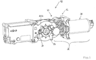
- FIG. 1 shows a drive device for a wing of a door or a window, which is generally designated by the reference numeral 10.
- the drive device 10 has a housing 12 and an output shaft 14 for actuating a between the frame and wing arranged lever mechanism (not shown), which serves for applying a torque to the wing.
- the drive device 10 has a mechanical energy store 16, by means of which the output shaft 14 can be driven (see FIG. 3 ).
- the housing 12 has an opening 18 for insertion of a blocking element 20 (see FIG. 1 ).
- the opening 18 is designed as a bore.
- the output shaft 14 is blocked when the blocking element 20 is inserted in a preloaded position (see FIG FIG. 4 ).
- the introduced blocking element 20 is in the present embodiment with a drive shaft 22 coupled to the drive element 22 in engagement.
- a passage 24 is formed for the blocking element 20, wherein the passage 24 in the biased position of the output shaft 14 is aligned with the opening 18.
- the passage 24 is formed as a bore.
- the drive element 22 is a toothed wheel or spur gear 26, which is non-rotatably coupled to the output shaft 14.
- the introduced blocking element 20 is arranged parallel to the axis of rotation of the output shaft 14.
- a further opening 28 for the blocking element 20 is formed (see FIG. 1 and 4 ).
- the opening 28 is also formed as a bore.
- the blocking element 20 is dimensioned in its length such that in the state introduced into the housing 12 the end sections of the blocking element 20 protrude out of the opening 18 and / or the further opening 28 (see FIG FIG. 1 and 2 ).
- an elastic border 30 is formed. This prevents accidental falling out of the blocking element 20 upon release of the bias.
- the elastic border 30 may be formed of rubber or rubber.
- the elastic border 30 may be an O-ring.
- the blocking element 20 is designed as a cylindrical pin 32.
- the blocking element 20 is chamfered at the end.
- the mechanical energy storage 16 is designed as a spring accumulator 34, which acts on a (not shown) curve of the output shaft 14.
- the drive device 10 has an electric drive unit 36 for driving the output shaft 14 against the drive direction applied by the energy accumulator 16 to the output shaft 14.
- the electric drive unit 36 has an electric motor 38 and a (multi-stage) gear 40.
- the gear or spur gear 26 forms part of this transmission 40.
- the drive device 10 has no electric drive unit, but only the mechanical energy storage as a drive for the output shaft.
- the advantages of assembly and maintenance work by the blocked by the blocking element output shaft can be achieved even with such a drive device.
Landscapes
- Engineering & Computer Science (AREA)
- Mechanical Engineering (AREA)
- Power-Operated Mechanisms For Wings (AREA)
Abstract
Eine Antriebsvorrichtung (10) für einen Flügel einer Tür oder eines Fensters, mit einem Gehäuse (12), einer Abtriebswelle (14) zur Betätigung einer zwischen Rahmen und Flügel angeordneten Hebelmechanik und einem mechanischen Energiespeicher (16), mittels dem die Abtriebswelle (14) antreibbar ist, ist im Hinblick auf eine sichere Montage mit einfachen konstruktiven Mitteln derart ausgestaltet und weitergebildet, dass das Gehäuse (12) eine Öffnung (18) zum Einführen eines Blockierelements (20) aufweist und dass die Abtriebswelle (14) bei eingeführtem Blockierelement (20) in einer vorgespannten Stellung blockiert ist.A drive device (10) for a wing of a door or a window, comprising a housing (12), an output shaft (14) for actuating a lever mechanism arranged between the frame and the wing and a mechanical energy accumulator (16), by means of which the output shaft (14) is driven, with regard to a secure mounting with simple constructive means designed and further developed such that the housing (12) has an opening (18) for introducing a blocking element (20) and that the output shaft (14) with inserted blocking element (20 ) is locked in a biased position.
Description
Die Erfindung betrifft eine Antriebsvorrichtung für einen Flügel einer Tür oder eines Fensters, mit einem Gehäuse, einer Abtriebswelle zur Betätigung einer zwischen Rahmen und Flügel angeordneten Hebelmechanik und einem mechanischen Energiespeicher, mittels dem die Abtriebswelle antreibbar ist.The invention relates to a drive device for a wing of a door or a window, comprising a housing, an output shaft for actuating a lever mechanism arranged between the frame and the wing, and a mechanical energy store, by means of which the output shaft can be driven.
Antriebsvorrichtungen der eingangs genannten Art sind aus dem Stand der Technik bekannt, beispielsweise aus
Allerdings besteht bei derartigen Antriebsvorrichtungen Verbesserungspotential im Hinblick auf deren Montage. Bei Antriebsvorrichtungen mit mechanischem Energiespeicher zum Antreiben der Abtriebswelle ist dieser mit einem Abschnitt der Abtriebswelle in Eingriff. Um einen Tür- oder Fensterflügel wie gewünscht antreiben zu können, ist es erforderlich, Flügelstellung, Stellung der Abtriebswelle und Positionierung der Hebelmechanik bei der Montage auf Grund der je nach Flügelstellung mittels der Hebelmechanik aufzubringenden Drehmomente genauestens einzuhalten. Da sich der Energiespeicher auch in einer Endstellung des Türflügels, beispielsweise der Schließstellung, zum Einhalten dieser Stellung in einem vorgespannten Zustand befinden muss, ist es erforderlich, die Hebelmechanik unter Vorspannung mit dem Türblatt zu verbinden. Dies erschwert die Montage. Gängige Montagemethode ist, die Abtriebswelle mit der Hebelmechanik an einem definierten Anschlag in Schließrichtung zu montieren, um im Anschluss den Hebelarm zum Erzeugen der Vorspannung relativ zur Abtriebswelle um einen vom Hersteller vorgegebenen Winkel zu versetzen und neu zu fixieren. Dies ist theoretisch halbwegs präzise machbar, in der Praxis jedoch stark fehlerbehaftet. Da die Montageschritte durch einen auf einer Leiter stehenden Werker beidhändig durchgeführt werden müssen, besteht zudem erhebliches Gefahrenpotential für den Werker und für Passanten. Auch bei Wartungsarbeiten hat eine Montage/Demontage der Antriebsvorrichtung in zwei Schritten zu erfolgen, da die Hebelmechanik zunächst entspannt werden muss, was entsprechend aufwändig ist.However, there is room for improvement in such drive devices with regard to their assembly. at Mechanical energy storage drive apparatus for driving the output shaft is engaged with a portion of the output shaft. In order to drive a door or window sash as desired, it is necessary to comply precisely wing position, position of the output shaft and positioning of the lever mechanism during assembly due to the applied depending on the sash position by means of the lever mechanism torques. Since the energy storage must also be in an end position of the door leaf, for example the closed position, to maintain this position in a prestressed state, it is necessary to connect the lever mechanism under pretension with the door leaf. This makes assembly difficult. Common mounting method is to mount the output shaft with the lever mechanism to a defined stop in the closing direction, to then move the lever arm for generating the bias relative to the output shaft by an angle specified by the manufacturer and re-fix. This is theoretically reasonably precisely feasible, but in practice strongly flawed. Since the assembly steps must be carried out by a person standing on a ladder ambidextrous, there is also considerable risk potential for the worker and for passers-by. Even during maintenance, a mounting / dismounting of the drive device has to be done in two steps, since the lever mechanism must first be relaxed, which is correspondingly expensive.
Der Erfindung liegt die Aufgabe zugrunde, mit einfachen konstruktiven Mitteln eine sichere Montage einer Antriebsvorrichtung für einen Flügel oder eine Tür zu ermöglichen. Eine Erleichterung von Wartungsarbeiten ist wünschenswert.The invention has for its object to enable with simple structural means secure mounting of a drive device for a wing or a door. Facilitation of maintenance is desirable.
Die Erfindung löst die Aufgabe mit einer Antriebsvorrichtung mit den Merkmalen des Anspruchs 1. Danach zeichnet sich die Antriebsvorrichtung dadurch aus, dass das Gehäuse eine Öffnung zum Einführen eines Blockierelements aufweist und dass die Abtriebswelle bei eingeführtem Blockierelement in einer definierten und vorgespannten Stellung blockierbar oder blockiert ist. Bei der Antriebsvorrichtung handelt es sich insbesondere um einen Drehantrieb oder Drehtürantrieb (schließt Drehfensterantriebe mit ein).The invention solves the problem with a drive device with the features of claim 1. Thereafter, the drive device is characterized in that the housing has an opening for insertion of a blocking element and that the output shaft is blocked or blocked in the inserted blocking element in a defined and biased position , The drive device is in particular a rotary drive or swing door drive (includes rotary window drives).
Durch das Blockierelement wird die Abtriebswelle in einem vorgespannten Zustand gehalten. Somit kann die Hebelmechanik ohne darauf wirkende Vorspannung montiert werden. Nach Entnahme des Blockierelements ist die Abtriebswelle freigegeben. Dadurch wird die Hebelmechanik unter Spannung versetzt. Eine Montage der Antriebsvorrichtung vor Ort ist damit erheblich erleichtert, da die Hebelmechanik erst nach Entnahme des Blockierelements unter Spannung steht. Die Öffnung kann beispielsweise als Bohrung ausgebildet sein. Die Hebelmechanik dient zum Aufbringen eines Drehmoments zwischen Flügel und Rahmen, beispielsweise vom Rahmen auf den Flügel.The blocking element keeps the output shaft in a prestressed state. Thus, the lever mechanism can be mounted without acting on bias. After removal of the blocking element, the output shaft is released. This puts the lever mechanism under tension. An assembly of the drive device on site is thus considerably easier, since the lever mechanism is only after removal of the blocking element under tension. The opening may be formed for example as a bore. The lever mechanism is used to apply a torque between the wing and frame, for example, from the frame on the wing.
Die definierte und vorgespannte Stellung der Abtriebswelle befindet sich kurz vor einer Endstellung der Abtriebswelle, in die die Abtriebswelle durch den Energiespeicher angetrieben wird. In dieser Stellung der Abtriebswelle befindet sich der Türflügel oder Fensterflügel kurz vor dessen Endlage, insbesondere kurz vor der geschlossenen Lage. Somit ist ein leichtes Entfernen des Blockierelements durch Andrücken des Flügels entgegen der Antriebsrichtung des Energiespeichers zum Ausgleich der durch den mechanischen Energiespeicher anliegenden Vorspannung möglich, beispielsweise durch Aufdrücken des Flügels. Durch die vordefinierten Montagepunkte der Hebelmechanik am Flügel oder am Rahmen ist stets die richtige Anordnung zwischen Abtriebswelle, Hebelmechanik und Türflügel gewährleistet.The defined and biased position of the output shaft is located shortly before an end position of the output shaft, in which the output shaft is driven by the energy storage. In this position, the output shaft, the door or window sash is just before the end position, especially shortly before the closed position. Thus, a slight removal of the blocking element by pressing the blade against the drive direction of the energy storage to compensate for by the mechanical energy storage adjacent bias possible, for example by pressing the wing. Due to the predefined mounting points of the lever mechanism on the wing or on the frame, the correct arrangement between the output shaft, lever mechanism and door leaf is always guaranteed.
Das Blockierelement ist derart ausgebildet, dass dieses (wiederholt) entnehmbar und einsetzbar ist. Dadurch sind auch Wartungsarbeiten an der Antriebsvorrichtung vereinfacht, da die Abtriebswelle hierzu, beispielsweise durch Andrücken des Flügels, lediglich in die definierte und vorgespannte Stellung verbracht und das Blockierelement in die Öffnung am Gehäuse eingeführt werden muss. Die Hebelmechanik ist dann spannungsfrei, so dass Wartungsarbeiten durchgeführt werden können. Nach Abschluss der Wartungsarbeiten kann das Blockierelement aus der Öffnung entnommen werden.The blocking element is designed such that it can be (repeatedly) removed and used. As a result, maintenance work on the drive device is simplified because the output shaft for this purpose, for example, by pressing the wing, spent only in the defined and biased position and the blocking element must be inserted into the opening on the housing. The lever mechanism is then tension-free so that maintenance work can be carried out. After completion of the maintenance work, the blocking element can be removed from the opening.
Im Rahmen einer bevorzugten Ausgestaltung kann das eingeführte Blockierelement mit der Abtriebswelle oder mit einem mit der Abtriebswelle gekoppelten oder zusammenwirkenden Antriebselement in Eingriff sein. Das Blockierelement verhindert eine Rotation der Abtriebswelle, beispielsweise auf sichere Weise durch Formschluss. Das Blockierelement wird insbesondere auf Schub belastet. Dabei kann das Blockierelement direkt mit der Abtriebswelle oder mit einer an der Abtriebswelle ausgebildeten Kurve in Kontakt sein. In diesem Fall erfolgt durch das Blockierelement ein direktes Blockieren der Abtriebswelle ohne Zwischenschaltung weiterer Komponenten. Bei Eingriff mit einem mit der Abtriebswelle gekoppelten oder zusammenwirkenden Antriebselement kann eine hinsichtlich Anordnung und Festigkeit ggf. günstigere Variante erreicht werden. Bei dem Antriebselement kann es sich um ein direkt oder indirekt mit der Abtriebswelle gekoppeltes Zahnrad oder Stirnrad handeln.In the context of a preferred embodiment, the introduced blocking element may be in engagement with the output shaft or with a drive element coupled or cooperating with the output shaft. The blocking element prevents rotation of the output shaft, for example in a secure manner by positive locking. The blocking element is particularly loaded on thrust. In this case, the blocking element may be in direct contact with the output shaft or with a curve formed on the output shaft. In this case, the blocking element directly blocks the output shaft without the interposition of other components. When engaged with a driven shaft coupled to or cooperating with the drive element, a possibly more favorable arrangement and strength can be achieved become. The drive element may be a gear or a spur gear directly or indirectly coupled to the output shaft.
Zweckmäßigerweise kann im Antriebselement ein Durchgang für das Blockierelement ausgebildet sein, wobei der Durchgang in der vorgespannten Stellung der Abtriebswelle mit der Öffnung fluchtet. Somit lässt sich eine eindeutige und präzise Ausrichtung der Abtriebswelle bezogen auf das Gehäuse der Antriebsvorrichtung erreichen. Der Durchgang lässt sich konstruktiv einfach erstellen, beispielsweise durch Bohren, so dass insgesamt eine konstruktiv günstige Ausrichtung der Abtriebswelle erreicht ist.Appropriately, a passage for the blocking element may be formed in the drive element, wherein the passage in the biased position of the output shaft is aligned with the opening. Thus, a clear and precise alignment of the output shaft relative to the housing of the drive device can be achieved. The passage can be structurally simple to create, for example, by drilling, so that overall a structurally favorable orientation of the output shaft is achieved.
Im Konkreten kann das eingeführte Blockierelement parallel zur Drehachse der Abtriebswelle angeordnet sein. Hiermit ist eine eindeutige Anordnung des Blockierelements im Gehäuse der Antriebsvorrichtung erreicht. Auf Grund dieser Orientierung des Blockierelements relativ zur Abtriebswelle kann das Blockierelement durch den Werker leicht eingeführt und herausgenommen werden.Specifically, the introduced blocking element may be arranged parallel to the axis of rotation of the output shaft. Hereby, a clear arrangement of the blocking element is achieved in the housing of the drive device. Due to this orientation of the blocking member relative to the output shaft, the blocking member can be easily inserted and removed by the worker.
In vorteilhafter Weise kann an der von der Öffnung abgewandten Seite des Gehäuses eine Ausnehmung (Ausnehmung an Gehäuseinnenseite ausgebildet) oder eine weitere Öffnung für das Blockierelement ausgebildet sein. Diese kann als Bohrung ausgebildet sein (Sackloch oder Durchgang). Dadurch ist eine stabile und zuverlässige beidseitige Lagerung des Blockierelements an dessen Endabschnitten erreicht. Durch Vorsehen einer weiteren Öffnung kann das Blockierelement von zwei Seiten in das Gehäuse eingeführt und aus diesem entnommen werden.Advantageously, on the side facing away from the opening of the housing, a recess (recess formed on the housing inner side) or a further opening for the blocking element may be formed. This can be designed as a hole (blind hole or passage). As a result, a stable and reliable two-sided storage of the blocking element is achieved at its end portions. By providing a further opening, the blocking element can be inserted from two sides into the housing and removed therefrom.
Im Rahmen einer bevorzugten Ausgestaltung kann das Blockierelement in seiner Länge derart bemessen sein, dass im in das Gehäuse eingeführten Zustand Endabschnitte des Blockierelements aus der Öffnung und/oder der weiteren Öffnung herausragen, beispielsweise um 1 bis 5 Millimeter an jeder Seite. Damit ist für einen Werker leicht erkennbar, ob die Abtriebswelle blockiert ist oder nicht. Zudem ist eine Entnahme des Blockierelements erleichtert, da der Werker das Blockierelement ausgehend von einer Seite in das Gehäuse zurückschieben und an der gegenüberliegenden Seite am nunmehr herausragenden Ende des Blockierelements dieses aus dem Gehäuse der Antriebsvorrichtung herausziehen kann. Eine Ausgestaltung zumindest der Endabschnitte des Blockierelements in Signalfarben (z.B. gelb, orange, rot, etc.) oder in Neonfarben erleichtert die Zustandserkennung für einen Werker. Dies reduziert das Risiko versehentlicher Arbeitsunfälle durch Fehlerkennung des Zustands der Abtriebswelle (blockiert oder nicht blockiert).In the context of a preferred embodiment, the blocking element can be dimensioned in its length such that, in the state introduced into the housing, end sections of the blocking element protrude out of the opening and / or the further opening, for example by 1 to 5 millimeters on each side. This makes it easy for a worker to see whether the output shaft is blocked or not. In addition, a removal of the blocking element is facilitated, since the worker can push the blocking element starting from one side into the housing and on the opposite side of the now outstanding end of the blocking element this can pull out of the housing of the drive device. An embodiment of at least the end portions of the blocking element in signal colors (e.g., yellow, orange, red, etc.) or in neon colors facilitates state recognition for a worker. This reduces the risk of accidental accidents at work by misrecognizing the state of the output shaft (blocked or not blocked).
Zweckmäßigerweise kann an der Öffnung und/oder an der weiteren Öffnung eine elastische Umrandung ausgebildet sein. Diese stellt eine Anordnung des Blockierelements im Gehäuse der Antriebsvorrichtung sicher und verhindert ein ungewolltes Herausfallen des Blockierelements bei Lösen der Vorspannung. Hierzu kann ein Reibschluss zwischen Umrandung und Blockierelement dienen. Die Umrandung kann aus einem elastischen Material, beispielsweise Gummi oder Kautschuk ausgebildet sein. Bei der Umrandung kann es sich insbesondere um einen O-Ring handeln.Conveniently, an elastic border may be formed at the opening and / or at the further opening. This ensures an arrangement of the blocking element in the housing of the drive device and prevents accidental falling out of the blocking element upon release of the bias voltage. For this purpose, a frictional engagement between the border and blocking element can be used. The border may be formed of an elastic material, such as rubber or rubber. The border may in particular be an O-ring.
Im Konkreten kann das Blockierelement als zylindrischer Stift ausgebildet sein. Hiermit ist eine konstruktiv einfache und kostengünstige Ausführung des Blockierelements erreicht. Aufgrund der zylindrischen Ausgestaltung ist eine gleichmäßige Belastung des Blockierelements durch gleichmäßige Anlage an Öffnungen im Gehäuse und/oder Durchgang im Antriebselement begünstigt. Das Blockierelement kann endseitig angefast oder abgerundet sein, um ein Einführen des Blockierelements zu erleichtern.Specifically, the blocking element may be formed as a cylindrical pin. Hereby, a structurally simple and cost-effective design of the blocking element is achieved. Due to the cylindrical configuration is a uniform loading of the blocking element by uniform contact with openings in the housing and / or passage in the drive element favors. The blocking element may be chamfered or rounded at the end to facilitate insertion of the blocking element.
Zweckmäßigerweise kann der Energiespeicher als Federspeicher ausgebildet sein. Hiermit ist ein konstruktiv einfacher und zugleich zuverlässiger Energiespeicher geschaffen.Conveniently, the energy storage can be designed as a spring store. This creates a structurally simple and reliable energy storage.
Im Konkreten kann die Antriebsvorrichtung eine elektrische Antriebseinheit zum Antrieb der Abtriebswelle entgegen der Antriebsrichtung des Energiespeichers umfassen. Damit ist eine motorische Betätigung des Türflügels oder Fensterflügels entgegen der durch den Energiespeicher auf die Abtriebswelle aufgebrachten Antriebsrichtung möglich. Die elektrische Antriebseinheit kann einen Elektromotor und ein insbesondere mehrstufiges Getriebe aufweisen. Außerdem kann die elektrische Antriebseinheit einem Antrieb durch den mechanischen Energiespeicher entgegen und daher als Dämpfer wirken. Die Vorteile bei Montage- und Wartungsarbeiten durch die mittels des Blockierelements blockierte Abtriebswelle lassen sich auch bei einer Antriebsvorrichtung erzielen, die lediglich einen mechanischen Energiespeicher als Antrieb für die Abtriebswelle aufweist.Specifically, the drive device may comprise an electric drive unit for driving the output shaft counter to the drive direction of the energy store. For a motor actuation of the door leaf or sash against the applied by the energy storage on the output shaft drive direction is possible. The electric drive unit may have an electric motor and a particular multi-stage transmission. In addition, the electric drive unit counteract a drive through the mechanical energy storage and therefore as a damper. The advantages of assembly and maintenance work by the blocked by the blocking element output shaft can also be achieved in a drive device having only a mechanical energy storage as a drive for the output shaft.
Die Antriebsvorrichtung kann als Inversantrieb ausgebildet sein, bei dem der mechanische Energiespeicher den Tür- oder Fensterflügel öffnet, beispielsweise im Notfall. Ebenfalls denkbar ist, dass die Antriebsvorrichtung als Normalantrieb ausgebildet ist, so dass der mechanische Energiespeicher den Tür- oder Fensterflügel schließt, beispielsweise im Notfall.The drive device can be designed as an inverse drive, in which the mechanical energy store opens the door or window sash, for example in an emergency. It is also conceivable that the drive device is designed as a normal drive, so that the mechanical energy storage closes the door or window sash, for example in an emergency.
Die Erfindung wird im Folgenden anhand der Figuren näher erläutert. Es zeigen:
- Figur 1
- in einer perspektivischen Ansicht eine Ausführungsform einer Antriebsvorichtung;
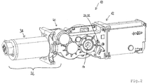
- Figur 2
- die Rückseite der Antriebsvorrichtung aus
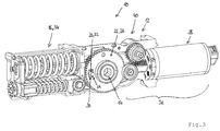
Figur 1 ; - Figur 3
- die Antriebsvorrichtung aus
Figur 1 bei abgenommener Gehäusehälfte; und - Figur 4
- die Antriebsvorrichtung aus
Figur 1 bei abgenommener Gehäusehälfte, entnommenem Kraftspeicher und entnommener elektrischer Antriebseinheit.
- FIG. 1
- in a perspective view of an embodiment of a Antriebsvorichtung;
- FIG. 2
- the back of the drive device
FIG. 1 ; - FIG. 3
- the drive device
FIG. 1 with removed housing half; and - FIG. 4
- the drive device
FIG. 1 with removed housing half, removed energy storage and removed electrical drive unit.
Das Gehäuse 12 weist eine Öffnung 18 zum Einführen eines Blockierelements 20 auf (siehe
Das eingeführte Blockierelement 20 ist im vorliegenden Ausführungsbeispiel mit einem mit der Abtriebswelle 14 gekoppelten Antriebselement 22 in Eingriff. Im Antriebselement 22 ist ein Durchgang 24 für das Blockierelement 20 ausgebildet, wobei der Durchgang 24 in der vorgespannten Stellung der Abtriebswelle 14 mit der Öffnung 18 fluchtet. Der Durchgang 24 ist als Bohrung ausgebildet. Bei dem Antriebselement 22 handelt es sich um ein Zahnrad oder Stirnrad 26, welches drehfest mit der Abtriebswelle 14 gekoppelt ist. Das eingeführte Blockierelement 20 ist parallel zur Drehachse der Abtriebswelle 14 angeordnet.The introduced blocking element 20 is in the present embodiment with a drive shaft 22 coupled to the drive element 22 in engagement. In the drive member 22, a
An der von der (ersten) Öffnung 18 abgewandten Seite des Gehäuses 12 ist eine weitere Öffnung 28 für das Blockierelement 20 ausgebildet (siehe
An der Öffnung 18 und/oder an der weiteren Öffnung 28 ist eine elastische Umrandung 30 ausgebildet. Diese verhindert ein ungewolltes Herausfallen des Blockierelements 20 bei Lösen der Vorspannung. Die elastische Umrandung 30 kann aus Kautschuk oder Gummi ausgebildet sein. Bei der elastischen Umrandung 30 kann es sich um einen O-Ring handeln.At the opening 18 and / or at the
Das Blockierelement 20 ist als zylindrischer Stift 32 ausgebildet. Das Blockierelement 20 ist endseitig angefast. Der mechanische Energiespeicher 16 ist als Federspeicher 34 ausgebildet, der auf eine (nicht dargestellte) Kurve der Abtriebswelle 14 wirkt.The blocking element 20 is designed as a cylindrical pin 32. The blocking element 20 is chamfered at the end. The mechanical energy storage 16 is designed as a spring accumulator 34, which acts on a (not shown) curve of the
Die Antriebsvorrichtung 10 weist eine elektrische Antriebseinheit 36 zum Antrieb der Abtriebswelle 14 entgegen der durch den Energiespeichers 16 auf die Abtriebswelle 14 aufgebrachten Antriebsrichtung auf. Die elektrische Antriebseinheit 36 weist einen Elektromotor 38 und ein (mehrstufiges) Getriebe 40 auf. Das Zahnrad oder Stirnrad 26 bildet einen Teil dieses Getriebes 40.The
Bei nicht dargestellten Ausführungsformen weist die Antriebsvorrichtung 10 keine elektrische Antriebseinheit, sondern lediglich den mechanischen Energiespeicher als Antrieb für die Abtriebswelle auf. Die Vorteile bei Montage- und Wartungsarbeiten durch die mittels des Blockierelements blockierte Abtriebswelle lassen sich auch bei einer solchen Antriebsvorrichtung erzielen.In embodiments not shown, the
Claims (10)
Priority Applications (1)
| Application Number | Priority Date | Filing Date | Title |
|---|---|---|---|
| EP16193890.7A EP3309339B1 (en) | 2016-10-14 | 2016-10-14 | Drive for a leaf of a door or window |
Applications Claiming Priority (1)
| Application Number | Priority Date | Filing Date | Title |
|---|---|---|---|
| EP16193890.7A EP3309339B1 (en) | 2016-10-14 | 2016-10-14 | Drive for a leaf of a door or window |
Publications (2)
| Publication Number | Publication Date |
|---|---|
| EP3309339A1 true EP3309339A1 (en) | 2018-04-18 |
| EP3309339B1 EP3309339B1 (en) | 2019-08-14 |
Family
ID=57136756
Family Applications (1)
| Application Number | Title | Priority Date | Filing Date |
|---|---|---|---|
| EP16193890.7A Active EP3309339B1 (en) | 2016-10-14 | 2016-10-14 | Drive for a leaf of a door or window |
Country Status (1)
| Country | Link |
|---|---|
| EP (1) | EP3309339B1 (en) |
Cited By (1)
| Publication number | Priority date | Publication date | Assignee | Title |
|---|---|---|---|---|
| EP3683392A1 (en) | 2019-01-16 | 2020-07-22 | dormakaba Deutschland GmbH | Door drive and method for mounting a door drive |
Citations (7)
| Publication number | Priority date | Publication date | Assignee | Title |
|---|---|---|---|---|
| US478354A (en) * | 1892-07-05 | Albert a | ||
| US664682A (en) * | 1900-07-20 | 1900-12-25 | Bommer Brothers | Spring-hinge. |
| US6006475A (en) * | 1998-03-04 | 1999-12-28 | Nabco Entrances Inc. | Spring loaded swinging door system |
| WO2006069888A1 (en) * | 2004-12-23 | 2006-07-06 | BSH Bosch und Siemens Hausgeräte GmbH | Hinge device and method for operating the same |
| EP2574713A2 (en) * | 2011-09-30 | 2013-04-03 | Dorma GmbH + Co. KG | Rotating leaf actuator and mounting of the same |
| DE102012104450A1 (en) | 2012-05-23 | 2013-11-28 | Gu Automatic Gmbh | Drive for e.g. door casement, has clockwork mechanisms independently adjustable and/or linkupable and cooperating with driven shaft, and motor comprising drive shaft located in active connection with gear box |
| DE202014103519U1 (en) * | 2014-07-29 | 2015-10-30 | Flap Competence Center Kft | Cover plate assembly |
-
2016
- 2016-10-14 EP EP16193890.7A patent/EP3309339B1/en active Active
Patent Citations (7)
| Publication number | Priority date | Publication date | Assignee | Title |
|---|---|---|---|---|
| US478354A (en) * | 1892-07-05 | Albert a | ||
| US664682A (en) * | 1900-07-20 | 1900-12-25 | Bommer Brothers | Spring-hinge. |
| US6006475A (en) * | 1998-03-04 | 1999-12-28 | Nabco Entrances Inc. | Spring loaded swinging door system |
| WO2006069888A1 (en) * | 2004-12-23 | 2006-07-06 | BSH Bosch und Siemens Hausgeräte GmbH | Hinge device and method for operating the same |
| EP2574713A2 (en) * | 2011-09-30 | 2013-04-03 | Dorma GmbH + Co. KG | Rotating leaf actuator and mounting of the same |
| DE102012104450A1 (en) | 2012-05-23 | 2013-11-28 | Gu Automatic Gmbh | Drive for e.g. door casement, has clockwork mechanisms independently adjustable and/or linkupable and cooperating with driven shaft, and motor comprising drive shaft located in active connection with gear box |
| DE202014103519U1 (en) * | 2014-07-29 | 2015-10-30 | Flap Competence Center Kft | Cover plate assembly |
Cited By (2)
| Publication number | Priority date | Publication date | Assignee | Title |
|---|---|---|---|---|
| EP3683392A1 (en) | 2019-01-16 | 2020-07-22 | dormakaba Deutschland GmbH | Door drive and method for mounting a door drive |
| US11603695B2 (en) | 2019-01-16 | 2023-03-14 | Dormakaba Deutschland Gmbh | Method for mounting a door drive and door drive |
Also Published As
| Publication number | Publication date |
|---|---|
| EP3309339B1 (en) | 2019-08-14 |
Similar Documents
| Publication | Publication Date | Title |
|---|---|---|
| EP2574713A2 (en) | Rotating leaf actuator and mounting of the same | |
| WO2021233974A1 (en) | Door opener comprising a push chain | |
| DE202011109983U1 (en) | Belt drive for tensile and compressive stress | |
| EP3309339B1 (en) | Drive for a leaf of a door or window | |
| EP1898041B1 (en) | Process and device for mounting attachments to building frames | |
| EP2227615B1 (en) | Drive system for a gate | |
| DE102005002102B4 (en) | locking device | |
| DE102007008667B4 (en) | Fastening device for an attachment element | |
| EP2789779A2 (en) | Fixing device for a sliding door of a motor vehicle | |
| EP2602412A2 (en) | Fitting device | |
| EP3348776B1 (en) | Fixing of a finger protection roller for gap covering | |
| EP2933412A1 (en) | Revolving door drive | |
| DE3503806C2 (en) | ||
| EP1418296B1 (en) | Secured emergency unlocking device and use thereof | |
| EP3242985B1 (en) | Motor lock | |
| DE102017100731A1 (en) | Unlocking device for opening a door with a panic lock, in particular a touchbar, with a drive for automatically opening the panic lock | |
| EP3725992A1 (en) | Drive | |
| DE202006014701U1 (en) | Refitting kit for e.g. blind, has protection unit fixing of bearing pin in bearing point of insert, where pin pertains to tubular motor drive component for electric motors drive of winding roller or to winding roller | |
| EP3029242B1 (en) | System for assembling a door element on a door installation | |
| DE102017119011A1 (en) | gear hinge | |
| DE102006011228A1 (en) | Door closing device for automatic closing of building door in alarm state, has retaining element mechanically coupled with lock rod over joint, lock rod and retaining element are positioned in different positions with non-locked joint | |
| EP2933410A1 (en) | Door drive | |
| DE102020126347B3 (en) | Spacer, guide rail for a venetian blind or venetian blind and venetian blind and blind and method therefor | |
| EP4045744B1 (en) | Fitting arrangement | |
| DE102017121833A1 (en) | Pulling device of a motor vehicle |
Legal Events
| Date | Code | Title | Description |
|---|---|---|---|
| PUAI | Public reference made under article 153(3) epc to a published international application that has entered the european phase |
Free format text: ORIGINAL CODE: 0009012 |
|
| STAA | Information on the status of an ep patent application or granted ep patent |
Free format text: STATUS: THE APPLICATION HAS BEEN PUBLISHED |
|
| AK | Designated contracting states |
Kind code of ref document: A1 Designated state(s): AL AT BE BG CH CY CZ DE DK EE ES FI FR GB GR HR HU IE IS IT LI LT LU LV MC MK MT NL NO PL PT RO RS SE SI SK SM TR |
|
| AX | Request for extension of the european patent |
Extension state: BA ME |
|
| STAA | Information on the status of an ep patent application or granted ep patent |
Free format text: STATUS: REQUEST FOR EXAMINATION WAS MADE |
|
| 17P | Request for examination filed |
Effective date: 20180928 |
|
| RBV | Designated contracting states (corrected) |
Designated state(s): AL AT BE BG CH CY CZ DE DK EE ES FI FR GB GR HR HU IE IS IT LI LT LU LV MC MK MT NL NO PL PT RO RS SE SI SK SM TR |
|
| GRAP | Despatch of communication of intention to grant a patent |
Free format text: ORIGINAL CODE: EPIDOSNIGR1 |
|
| STAA | Information on the status of an ep patent application or granted ep patent |
Free format text: STATUS: GRANT OF PATENT IS INTENDED |
|
| RIC1 | Information provided on ipc code assigned before grant |
Ipc: E05D 11/10 20060101ALN20181218BHEP Ipc: E05F 15/63 20150101ALI20181218BHEP Ipc: E05F 1/10 20060101ALI20181218BHEP Ipc: E05F 3/22 20060101AFI20181218BHEP |
|
| GRAJ | Information related to disapproval of communication of intention to grant by the applicant or resumption of examination proceedings by the epo deleted |
Free format text: ORIGINAL CODE: EPIDOSDIGR1 |
|
| STAA | Information on the status of an ep patent application or granted ep patent |
Free format text: STATUS: REQUEST FOR EXAMINATION WAS MADE |
|
| INTG | Intention to grant announced |
Effective date: 20190121 |
|
| GRAP | Despatch of communication of intention to grant a patent |
Free format text: ORIGINAL CODE: EPIDOSNIGR1 |
|
| STAA | Information on the status of an ep patent application or granted ep patent |
Free format text: STATUS: GRANT OF PATENT IS INTENDED |
|
| INTC | Intention to grant announced (deleted) | ||
| INTG | Intention to grant announced |
Effective date: 20190222 |
|
| RIC1 | Information provided on ipc code assigned before grant |
Ipc: E05D 11/10 20060101ALN20190208BHEP Ipc: E05F 1/10 20060101ALI20190208BHEP Ipc: E05F 3/22 20060101AFI20190208BHEP Ipc: E05F 15/63 20150101ALI20190208BHEP |
|
| GRAS | Grant fee paid |
Free format text: ORIGINAL CODE: EPIDOSNIGR3 |
|
| GRAA | (expected) grant |
Free format text: ORIGINAL CODE: 0009210 |
|
| STAA | Information on the status of an ep patent application or granted ep patent |
Free format text: STATUS: THE PATENT HAS BEEN GRANTED |
|
| AK | Designated contracting states |
Kind code of ref document: B1 Designated state(s): AL AT BE BG CH CY CZ DE DK EE ES FI FR GB GR HR HU IE IS IT LI LT LU LV MC MK MT NL NO PL PT RO RS SE SI SK SM TR |
|
| REG | Reference to a national code |
Ref country code: GB Ref legal event code: FG4D Free format text: NOT ENGLISH |
|
| REG | Reference to a national code |
Ref country code: CH Ref legal event code: EP Ref country code: AT Ref legal event code: REF Ref document number: 1167229 Country of ref document: AT Kind code of ref document: T Effective date: 20190815 |
|
| REG | Reference to a national code |
Ref country code: CH Ref legal event code: NV Representative=s name: DREISS PATENTANWAELTE PARTG MBB, DE |
|
| REG | Reference to a national code |
Ref country code: IE Ref legal event code: FG4D Free format text: LANGUAGE OF EP DOCUMENT: GERMAN |
|
| REG | Reference to a national code |
Ref country code: DE Ref legal event code: R096 Ref document number: 502016006062 Country of ref document: DE |
|
| REG | Reference to a national code |
Ref country code: NL Ref legal event code: MP Effective date: 20190814 |
|
| REG | Reference to a national code |
Ref country code: LT Ref legal event code: MG4D |
|
| PG25 | Lapsed in a contracting state [announced via postgrant information from national office to epo] |
Ref country code: BG Free format text: LAPSE BECAUSE OF FAILURE TO SUBMIT A TRANSLATION OF THE DESCRIPTION OR TO PAY THE FEE WITHIN THE PRESCRIBED TIME-LIMIT Effective date: 20191114 Ref country code: NL Free format text: LAPSE BECAUSE OF FAILURE TO SUBMIT A TRANSLATION OF THE DESCRIPTION OR TO PAY THE FEE WITHIN THE PRESCRIBED TIME-LIMIT Effective date: 20190814 Ref country code: HR Free format text: LAPSE BECAUSE OF FAILURE TO SUBMIT A TRANSLATION OF THE DESCRIPTION OR TO PAY THE FEE WITHIN THE PRESCRIBED TIME-LIMIT Effective date: 20190814 Ref country code: SE Free format text: LAPSE BECAUSE OF FAILURE TO SUBMIT A TRANSLATION OF THE DESCRIPTION OR TO PAY THE FEE WITHIN THE PRESCRIBED TIME-LIMIT Effective date: 20190814 Ref country code: PT Free format text: LAPSE BECAUSE OF FAILURE TO SUBMIT A TRANSLATION OF THE DESCRIPTION OR TO PAY THE FEE WITHIN THE PRESCRIBED TIME-LIMIT Effective date: 20191216 Ref country code: LT Free format text: LAPSE BECAUSE OF FAILURE TO SUBMIT A TRANSLATION OF THE DESCRIPTION OR TO PAY THE FEE WITHIN THE PRESCRIBED TIME-LIMIT Effective date: 20190814 Ref country code: FI Free format text: LAPSE BECAUSE OF FAILURE TO SUBMIT A TRANSLATION OF THE DESCRIPTION OR TO PAY THE FEE WITHIN THE PRESCRIBED TIME-LIMIT Effective date: 20190814 Ref country code: NO Free format text: LAPSE BECAUSE OF FAILURE TO SUBMIT A TRANSLATION OF THE DESCRIPTION OR TO PAY THE FEE WITHIN THE PRESCRIBED TIME-LIMIT Effective date: 20191114 |
|
| PG25 | Lapsed in a contracting state [announced via postgrant information from national office to epo] |
Ref country code: LV Free format text: LAPSE BECAUSE OF FAILURE TO SUBMIT A TRANSLATION OF THE DESCRIPTION OR TO PAY THE FEE WITHIN THE PRESCRIBED TIME-LIMIT Effective date: 20190814 Ref country code: GR Free format text: LAPSE BECAUSE OF FAILURE TO SUBMIT A TRANSLATION OF THE DESCRIPTION OR TO PAY THE FEE WITHIN THE PRESCRIBED TIME-LIMIT Effective date: 20191115 Ref country code: RS Free format text: LAPSE BECAUSE OF FAILURE TO SUBMIT A TRANSLATION OF THE DESCRIPTION OR TO PAY THE FEE WITHIN THE PRESCRIBED TIME-LIMIT Effective date: 20190814 Ref country code: IS Free format text: LAPSE BECAUSE OF FAILURE TO SUBMIT A TRANSLATION OF THE DESCRIPTION OR TO PAY THE FEE WITHIN THE PRESCRIBED TIME-LIMIT Effective date: 20191214 Ref country code: ES Free format text: LAPSE BECAUSE OF FAILURE TO SUBMIT A TRANSLATION OF THE DESCRIPTION OR TO PAY THE FEE WITHIN THE PRESCRIBED TIME-LIMIT Effective date: 20190814 Ref country code: AL Free format text: LAPSE BECAUSE OF FAILURE TO SUBMIT A TRANSLATION OF THE DESCRIPTION OR TO PAY THE FEE WITHIN THE PRESCRIBED TIME-LIMIT Effective date: 20190814 |
|
| PG25 | Lapsed in a contracting state [announced via postgrant information from national office to epo] |
Ref country code: TR Free format text: LAPSE BECAUSE OF FAILURE TO SUBMIT A TRANSLATION OF THE DESCRIPTION OR TO PAY THE FEE WITHIN THE PRESCRIBED TIME-LIMIT Effective date: 20190814 |
|
| PG25 | Lapsed in a contracting state [announced via postgrant information from national office to epo] |
Ref country code: DK Free format text: LAPSE BECAUSE OF FAILURE TO SUBMIT A TRANSLATION OF THE DESCRIPTION OR TO PAY THE FEE WITHIN THE PRESCRIBED TIME-LIMIT Effective date: 20190814 Ref country code: EE Free format text: LAPSE BECAUSE OF FAILURE TO SUBMIT A TRANSLATION OF THE DESCRIPTION OR TO PAY THE FEE WITHIN THE PRESCRIBED TIME-LIMIT Effective date: 20190814 Ref country code: RO Free format text: LAPSE BECAUSE OF FAILURE TO SUBMIT A TRANSLATION OF THE DESCRIPTION OR TO PAY THE FEE WITHIN THE PRESCRIBED TIME-LIMIT Effective date: 20190814 Ref country code: IT Free format text: LAPSE BECAUSE OF FAILURE TO SUBMIT A TRANSLATION OF THE DESCRIPTION OR TO PAY THE FEE WITHIN THE PRESCRIBED TIME-LIMIT Effective date: 20190814 Ref country code: PL Free format text: LAPSE BECAUSE OF FAILURE TO SUBMIT A TRANSLATION OF THE DESCRIPTION OR TO PAY THE FEE WITHIN THE PRESCRIBED TIME-LIMIT Effective date: 20190814 |
|
| PG25 | Lapsed in a contracting state [announced via postgrant information from national office to epo] |
Ref country code: IS Free format text: LAPSE BECAUSE OF FAILURE TO SUBMIT A TRANSLATION OF THE DESCRIPTION OR TO PAY THE FEE WITHIN THE PRESCRIBED TIME-LIMIT Effective date: 20200224 Ref country code: SM Free format text: LAPSE BECAUSE OF FAILURE TO SUBMIT A TRANSLATION OF THE DESCRIPTION OR TO PAY THE FEE WITHIN THE PRESCRIBED TIME-LIMIT Effective date: 20190814 Ref country code: MC Free format text: LAPSE BECAUSE OF FAILURE TO SUBMIT A TRANSLATION OF THE DESCRIPTION OR TO PAY THE FEE WITHIN THE PRESCRIBED TIME-LIMIT Effective date: 20190814 Ref country code: SK Free format text: LAPSE BECAUSE OF FAILURE TO SUBMIT A TRANSLATION OF THE DESCRIPTION OR TO PAY THE FEE WITHIN THE PRESCRIBED TIME-LIMIT Effective date: 20190814 Ref country code: CZ Free format text: LAPSE BECAUSE OF FAILURE TO SUBMIT A TRANSLATION OF THE DESCRIPTION OR TO PAY THE FEE WITHIN THE PRESCRIBED TIME-LIMIT Effective date: 20190814 |
|
| REG | Reference to a national code |
Ref country code: DE Ref legal event code: R097 Ref document number: 502016006062 Country of ref document: DE |
|
| PLBE | No opposition filed within time limit |
Free format text: ORIGINAL CODE: 0009261 |
|
| STAA | Information on the status of an ep patent application or granted ep patent |
Free format text: STATUS: NO OPPOSITION FILED WITHIN TIME LIMIT |
|
| PG2D | Information on lapse in contracting state deleted |
Ref country code: IS |
|
| PG25 | Lapsed in a contracting state [announced via postgrant information from national office to epo] |
Ref country code: LU Free format text: LAPSE BECAUSE OF NON-PAYMENT OF DUE FEES Effective date: 20191014 |
|
| 26N | No opposition filed |
Effective date: 20200603 |
|
| REG | Reference to a national code |
Ref country code: BE Ref legal event code: MM Effective date: 20191031 |
|
| PG25 | Lapsed in a contracting state [announced via postgrant information from national office to epo] |
Ref country code: BE Free format text: LAPSE BECAUSE OF NON-PAYMENT OF DUE FEES Effective date: 20191031 Ref country code: SI Free format text: LAPSE BECAUSE OF FAILURE TO SUBMIT A TRANSLATION OF THE DESCRIPTION OR TO PAY THE FEE WITHIN THE PRESCRIBED TIME-LIMIT Effective date: 20190814 |
|
| PG25 | Lapsed in a contracting state [announced via postgrant information from national office to epo] |
Ref country code: FR Free format text: LAPSE BECAUSE OF NON-PAYMENT OF DUE FEES Effective date: 20191014 Ref country code: IE Free format text: LAPSE BECAUSE OF NON-PAYMENT OF DUE FEES Effective date: 20191014 |
|
| REG | Reference to a national code |
Ref country code: DE Ref legal event code: R082 Ref document number: 502016006062 Country of ref document: DE |
|
| PG25 | Lapsed in a contracting state [announced via postgrant information from national office to epo] |
Ref country code: CY Free format text: LAPSE BECAUSE OF FAILURE TO SUBMIT A TRANSLATION OF THE DESCRIPTION OR TO PAY THE FEE WITHIN THE PRESCRIBED TIME-LIMIT Effective date: 20190814 |
|
| GBPC | Gb: european patent ceased through non-payment of renewal fee |
Effective date: 20201014 |
|
| PG25 | Lapsed in a contracting state [announced via postgrant information from national office to epo] |
Ref country code: MT Free format text: LAPSE BECAUSE OF FAILURE TO SUBMIT A TRANSLATION OF THE DESCRIPTION OR TO PAY THE FEE WITHIN THE PRESCRIBED TIME-LIMIT Effective date: 20190814 Ref country code: HU Free format text: LAPSE BECAUSE OF FAILURE TO SUBMIT A TRANSLATION OF THE DESCRIPTION OR TO PAY THE FEE WITHIN THE PRESCRIBED TIME-LIMIT; INVALID AB INITIO Effective date: 20161014 |
|
| PG25 | Lapsed in a contracting state [announced via postgrant information from national office to epo] |
Ref country code: GB Free format text: LAPSE BECAUSE OF NON-PAYMENT OF DUE FEES Effective date: 20201014 |
|
| PG25 | Lapsed in a contracting state [announced via postgrant information from national office to epo] |
Ref country code: MK Free format text: LAPSE BECAUSE OF FAILURE TO SUBMIT A TRANSLATION OF THE DESCRIPTION OR TO PAY THE FEE WITHIN THE PRESCRIBED TIME-LIMIT Effective date: 20190814 |
|
| PGFP | Annual fee paid to national office [announced via postgrant information from national office to epo] |
Ref country code: DE Payment date: 20231020 Year of fee payment: 8 Ref country code: CH Payment date: 20231102 Year of fee payment: 8 Ref country code: AT Payment date: 20231020 Year of fee payment: 8 |