EP3309066A1 - Procede de liaison entre l'arbre d'un tachy-metre et une roue d'aeronef - Google Patents
Procede de liaison entre l'arbre d'un tachy-metre et une roue d'aeronef Download PDFInfo
- Publication number
- EP3309066A1 EP3309066A1 EP17196247.5A EP17196247A EP3309066A1 EP 3309066 A1 EP3309066 A1 EP 3309066A1 EP 17196247 A EP17196247 A EP 17196247A EP 3309066 A1 EP3309066 A1 EP 3309066A1
- Authority
- EP
- European Patent Office
- Prior art keywords
- housing
- shaft
- sleeve
- wheel
- tachometer
- Prior art date
- Legal status (The legal status is an assumption and is not a legal conclusion. Google has not performed a legal analysis and makes no representation as to the accuracy of the status listed.)
- Granted
Links
Images


Classifications
-
- B—PERFORMING OPERATIONS; TRANSPORTING
- B64—AIRCRAFT; AVIATION; COSMONAUTICS
- B64C—AEROPLANES; HELICOPTERS
- B64C25/00—Alighting gear
- B64C25/32—Alighting gear characterised by elements which contact the ground or similar surface
- B64C25/34—Alighting gear characterised by elements which contact the ground or similar surface wheeled type, e.g. multi-wheeled bogies
- B64C25/36—Arrangements or adaptations of wheels, tyres or axles in general
-
- G—PHYSICS
- G01—MEASURING; TESTING
- G01P—MEASURING LINEAR OR ANGULAR SPEED, ACCELERATION, DECELERATION, OR SHOCK; INDICATING PRESENCE, ABSENCE, OR DIRECTION, OF MOVEMENT
- G01P1/00—Details of instruments
- G01P1/04—Special adaptations of driving means
-
- B—PERFORMING OPERATIONS; TRANSPORTING
- B64—AIRCRAFT; AVIATION; COSMONAUTICS
- B64C—AEROPLANES; HELICOPTERS
- B64C25/00—Alighting gear
- B64C25/32—Alighting gear characterised by elements which contact the ground or similar surface
- B64C25/34—Alighting gear characterised by elements which contact the ground or similar surface wheeled type, e.g. multi-wheeled bogies
Definitions
- the invention relates to a method for connecting the shaft of a tachometer and an aircraft wheel.
- the wheel cover comprises a central housing in which the end of the shaft of the tachometer is engaged.
- the drive is provided by the non-circular section (eg hexagonal or fluted) of the end of the shaft of the tachometer and housing.
- the invention aims to provide a method of connection between the tachometer shaft and the wheel which reduces the noise of the signal, especially at low rotational speed.
- a method of connection between an end of a tachometer shaft disposed in a landing gear axle and a wheel rotatably mounted on said axle comprising the step of equipping the wheel of a housing adapted to receive the end of the shaft of a tachometer and driving the shaft in rotation with the wheel, the housing comprising according to the invention a bearing member projecting inside the housing to be pushed by the end of the shaft against an elastic member for make up any play between the end of the tree and the housing.
- the housing comprises a grooved inlet followed by a receptacle for a sleeve rotatably mounted in the receptacle.
- the support member is a lug inside the sleeve and the elastic member comprises a torsion spring acting on the sleeve to return it to a position in which the lug extends between two grooves when the end is not engaged in housing.
- the housing is formed in the hollow body of a bushing comprising a flange for fixing the bushing to a cover integral with the wheel.
- the invention also relates to a sleeve intended to be attached to the aircraft wheel cover for receiving and driving an end of a tachometer shaft housed in a landing gear axle carrying the wheel.
- the socket has a hollow body defining a housing in which the end is received.
- the housing comprises an inlet of section homologous to that of the end followed by a cylindrical receptacle receiving a sleeve which comes in continuity with the inlet of the housing to receive the end and which is mounted to rotation in the receptacle.
- the sleeve comprises a bearing member projecting towards the inside of the sleeve which extends so as to be pushed by the end when the latter is engaged in the housing against a return force exerted by a elastic member.
- the invention applies to an undercarriage with an axle 1 which receives a wheel 2 which can be seen here the rim provided with its bearings 3. Inside the axle 1 is inserted a cartridge 4 having a motor 5 driving a fan 6, and at the rear of the engine 5, a tachometer 7 which can be seen the shaft 8 through the motor 5, the fan 6 to open out of the axle 1.
- L 8 has a fluted end 9 which is engaged in a bushing 10 secured to a cover 11 for protecting the wheel which he is in solidarity.
- the rotation of the wheel causes the rotation of the shaft 8, which causes the tachometer 7 to generate a signal representative of the speed of rotation of the wheel.
- the sleeve 10 comprises a hollow body 12 terminated by a flange 13 allowing its screwing on the cover 11.
- the hollow body 12 defines a housing 14 having a grooved inlet for receiving the end 9 of the shaft 8.
- the housing 14 defines a cylindrical receptacle 15 which receives a sleeve 16 which comes in continuity with the inlet of the housing 14 to receive the end 9 of the shaft 8.
- the sleeve 16 comprises an inner lug 17.
- the sleeve 16 is rotatably mounted in the cylindrical receptacle 15 being connected to a plug 19 which closes the interior of the hollow body 12 by means of a torsion spring 18 which recalls the sleeve 16 to an angular position in which the lug 17 protrudes between two grooves of the housing inlet 14 when the end 9 of the shaft 8 is not engaged in the housing.
- the Figure 4A shows the pin 17 which protrudes between two grooves of the housing.
- the splines of the end 9 pass into the grooves homologous to the entrance of the housing 14, then, continuing to penetrate, push the lug 17, forcing the sleeve 16 to rotate in its receptacle 15 against a return force exerted by the torsion spring 18.
- the lug 17 presses the splines of the end 9 of the shaft 8 to press them against the flutes homologous to the housing 14, thus catching any play between the grooves of the housing 14 and the splines of the end 9. This provision causes a significant decrease in noise parasitizing the tachometer signal.
- the inlet of the housing 14 has a flared shape, allowing a slight swiveling of the end 9 of the shaft 8 in the housing 14, which further contributes to reducing the stresses on the shaft 8 and thus reducing the noise produced by the tachometer signal. Still to allow this slight swiveling, the length of the grooves of the housing 14 have been reduced to a minimum, to accommodate a slight angle between the axis of the shaft 8 and the central axis of the housing 14.
- the housing is part of a socket 10 attached to the wheel cover, it will more generally be able to equip the wheel with a housing with a support member bearing on the end of the shaft against the action of an elastic member to catch any play between the end of the shaft and the housing.
Landscapes
- Engineering & Computer Science (AREA)
- Mechanical Engineering (AREA)
- Aviation & Aerospace Engineering (AREA)
- Physics & Mathematics (AREA)
- General Physics & Mathematics (AREA)
- Gears, Cams (AREA)
- General Details Of Gearings (AREA)
- Motor Power Transmission Devices (AREA)
- Braking Arrangements (AREA)
Abstract
Description
- L'invention concerne un procédé pour relier l'arbre d'un tachymètre et une roue d'aéronef.
- Dans le domaine des atterrisseurs d'aéronef, il est d'usage de mesurer la vitesse de rotation des roues freinées pour assurer la régulation du freinage. A cet effet, il est connu d'installer un tachymètre dans l'essieu dont l'arbre saille de l'essieu de sorte que son extrémité soit entraînée en rotation par un capot solidaire de la roue. Le tachymètre délivre un signal représentatif de la vitesse de rotation de la roue. A cet effet, le capot de roue comporte un logement central dans lequel l'extrémité de l'arbre du tachymètre est engagée. L'entraînement est assuré par la section non-circulaire (par exemple hexagonale ou cannelée) de l'extrémité de l'arbre du tachymètre et du logement. Il est apparu qu'à faible vitesse, le signal du tachymètre était parfois bruité au point de ne pouvoir être utilisé efficacement pour la régulation du freinage.
- On a bien entendu tenté de filtrer le signal du tachymètre, mais le bruit est parfois tellement important qu'il masque complètement l'information utilisable.
- L'invention vise à proposer un procédé de liaison entre l'arbre du tachymètre et la roue qui réduit le bruit du signal, notamment à faible vitesse de rotation.
- En vue de la réalisation de ce but, on propose un procédé de liaison entre une extrémité d'un arbre de tachymètre disposé dans un essieu d'atterrisseur et une roue montée à rotation sur ledit essieu, le procédé comportant l'étape d'équiper la roue d'un logement adapté à recevoir l'extrémité de l'arbre d'un tachymètre et entraîner l'arbre en rotation avec la roue, le logement comportant selon l'invention un organe d'appui saillant à l'intérieur du logement pour être repoussé par l'extrémité de l'arbre à l'encontre d'un organe élastique pour rattraper tout jeu entre l'extrémité de l'arbre et le logement.
- Grâce au rattrapage de jeu ainsi mis en oeuvre selon l'invention, on a constaté une réduction spectaculaire du bruit perturbant le signal du tachymètre aux basses vitesses, à tel point que des tachymètres réformés selon les critères de réception actuels délivrent de nouveau des signaux parfaitement utilisables pour la régulation de freinage.
- Selon une caractéristique particulière, le logement comporte une entrée cannelée suivie d'un réceptacle pour un manchon monté tournant dans le réceptacle. L'organe d'appui est un ergot intérieur au manchon et l'organe élastique comporte un ressort de torsion agissant sur le manchon pour le rappeler vers une position dans laquelle l'ergot s'étend entre deux cannelures lorsque l'extrémité n'est pas engagée dans le logement.
- Selon une autre caractéristique particulière, le logement est ménagé dans le corps creux d'une douille comportant une collerette pour la fixation de la douille à un capot solidaire de la roue.
- L'invention est également relative à une douille destinée à être rapportée sur le capot de roue d'aéronef pour recevoir et entraîner une extrémité d'un arbre de tachymètre logé dans un essieu d'atterrisseur portant la roue. La douille comporte un corps creux définissant un logement dans lequel l'extrémité est reçue. Le logement comporte une entrée de section homologue à celle de l'extrémité suivie d'un réceptacle cylindrique recevant un manchon qui vient en continuité de l'entrée du logement pour recevoir l'extrémité et qui est monté à rotation dans le réceptacle. Le manchon comporte un organe d'appui saillant vers l'intérieur du manchon qui s'étend de façon à être repoussé par l'extrémité quand celle-ci est engagée dans le logement à l'encontre d'un effort de rappel exercé par un organe élastique.
- L'invention sera mieux comprise à la lumière de la description qui suit d'un mode de mise en oeuvre de l'invention, en référence aux figures des dessins annexés parmi lesquelles :
- la
figure 1 est une vue en coupe d'un essieu d'atterrisseur équipé de sa roue et d'un tachymètre, avec la douille d'entraînement selon l'invention placé sur le capot de roue ; - la
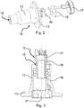
figure 2 est une vue éclatée d'une douille selon l'invention ; - la
figure 3 est une vue en coupe de la douille de lafigure 2 ; - les
figures 4A et 4B sont des vues de face montrant l'intérieur du logement de la douille, avant l'introduction de l'extrémité de l'arbre du tachymètre, et après son introduction. - L'invention s'applique à un atterrisseur dont on voit un essieu 1 qui reçoit une roue 2 dont on aperçoit ici la jante munie de ses roulements 3. A l'intérieur de l'essieu 1 est insérée une cartouche 4 comportant un moteur 5 d'entraînement d'un ventilateur 6, et, à l'arrière du moteur 5, un tachymètre 7 dont on voit l'arbre 8 traverser le moteur 5, le ventilateur 6 pour déboucher à l'extérieur de l'essieu 1. L'arbre 8 a une extrémité cannelée 9 qui est engagée dans une douille 10 solidarisée à un capot 11 de protection de la roue qui lui est solidaire. Ainsi, la rotation de la roue entraîne la rotation de l'arbre 8, ce qui conduit le tachymètre 7 à générer un signal représentatif de la vitesse de la rotation de la roue.
- En référence aux
figures 2 et 3 , la douille 10 comporte un corps creux 12 terminé par une collerette 13 permettant son vissage sur le capot 11. Le corps creux 12 définit un logement 14 ayant une entrée cannelée pour recevoir l'extrémité 9 de l'arbre 8. Après l'entrée, le logement 14 définit un réceptacle cylindrique 15 qui reçoit un manchon 16 qui vient en continuité de l'entrée du logement 14 pour recevoir l'extrémité 9 de l'arbre 8. Le manchon 16 comporte un ergot 17 intérieur. Le manchon 16 est monté tournant dans le réceptacle cylindrique 15 en étant relié à un bouchon 19 qui ferme l'intérieur du corps creux 12 au moyen d'un ressort de torsion 18 qui rappelle le manchon 16 vers une une position angulaire dans laquelle l'ergot 17 saille entre deux cannelures de l'entrée du logement 14 lorsque l'extrémité 9 de l'arbre 8 n'est pas engagée dans le logement. - La
figure 4A montre l'ergot 17 qui saille entre deux cannelures du logement. Lors de l'introduction de l'extrémité cannelée 9 de l'arbre 8 illustrée à lafigure 4B , les cannelures de l'extrémité 9 passent dans les cannelures homologues de l'entrée du logement 14, puis, continuant à pénétrer, repoussent l'ergot 17, obligeant ainsi le manchon 16 à tourner dans son réceptacle 15 à l'encontre d'un effort de rappel exercé par le ressort de torsion 18. Par réaction, l'ergot 17 appuie sur les cannelures de l'extrémité 9 de l'arbre 8 pour les plaquer contre les cannelures homologues du logement 14, rattrapant ainsi tout jeu entre les cannelures du logement 14 et les cannelures de l'extrémité 9. Cette disposition entraîne une diminution notable du bruit parasitant le signal du tachymètre. - On remarquera que l'entrée du logement 14 est de forme évasée, permettant un léger rotulage de l'extrémité 9 de l'arbre 8 dans le logement 14, ce qui contribue encore à diminuer les contraintes sur l'arbre 8 et ainsi diminuer la production de bruit parasitant le signal du tachymètre. Toujours pour permettre ce léger rotulage, la longueur des cannelures du logement 14 ont été réduites au strict minimum, pour s'accommoder d'un léger angle entre l'axe de l'arbre 8 et l'axe central du logement 14. Ces dispositions permettent d'absorber une flexion de l'essieu à l'atterrissage et au roulage, due aux efforts que le sol applique à la roue portée par l'essieu.
- L'invention n'est pas limitée à ce qui vient d'être décrit mais englobe toute variante entrant dans le cadre défini par les revendications.
- En particulier, bien qu'ici le logement fasse partie d'une douille 10 rapportée sur le capot de roue, on pourra de façon plus générale équiper la roue d'un logement avec un organe d'appui venant en appui sur l'extrémité de l'arbre à l'encontre de l'action d'un organe élastique pour rattraper tout jeu entre l'extrémité de l'arbre et le logement.
Claims (4)
- Procédé de liaison entre une extrémité (9) d'un arbre (8) de tachymètre (7) disposé dans un essieu d'atterrisseur (1) et une roue (2) montée à rotation sur ledit essieu, le procédé comportant l'étape d'équiper la roue d'un logement (14) adapté à recevoir l'extrémité de l'arbre d'un tachymètre et entraîner l'arbre en rotation avec la roue, le logement comportant un organe d'appui (17) saillant à l'intérieur du logement pour être repoussé par l'extrémité de l'arbre à l'encontre d'un organe élastique (18) pour rattraper tout jeu entre l'extrémité de l'arbre et le logement.
- Procédé selon la revendication 1, dans lequel le logement comporte une entrée cannelée suivie d'un réceptacle (15) pour un manchon (16) monté tournant dans le réceptacle, l'organe d'appui étant un ergot intérieur au manchon, l'organe élastique comportant un ressort de torsion agissant sur le manchon pour le rappeler vers une position dans laquelle l'ergot s'étend entre deux cannelures lorsque l'extrémité n'est pas engagée dans le logement.
- Procédé selon la revendication 1, dans lequel le logement est ménagé dans le corps creux (12) d'une douille (10) comportant une collerette (13) pour la fixation de la douille à un capot solidaire de la roue.
- Douille destinée à être rapportée sur un capot de roue d'aéronef pour recevoir et entraîner une extrémité (9) d'un arbre de tachymètre logé dans un essieu d'atterrisseur portant la roue, la douille comportant un corps creux (12) définissant un logement dans lequel l'extrémité est reçue, le logement ayant une entrée de section homologue à celle de l'extrémité suivie d'un réceptacle cylindrique (15) qui reçoit un manchon (16) qui vient en continuité de l'entrée du logement (14) pour recevoir l'extrémité (9) et qui est monté à rotation dans le réceptacle, le manchon ayant un organe d'appui saillant vers l'intérieur du manchon qui s'étend de façon à être repoussé par l'extrémité quand celle-ci est engagée dans le logement à l'encontre d'un effort de rappel exercé par un organe élastique (18).
Applications Claiming Priority (1)
| Application Number | Priority Date | Filing Date | Title |
|---|---|---|---|
| FR1659914A FR3057630B1 (fr) | 2016-10-13 | 2016-10-13 | Procede de liaison entre l'arbre d'un tachymetre et une roue d'aeronef |
Publications (2)
| Publication Number | Publication Date |
|---|---|
| EP3309066A1 true EP3309066A1 (fr) | 2018-04-18 |
| EP3309066B1 EP3309066B1 (fr) | 2021-12-01 |
Family
ID=57485770
Family Applications (1)
| Application Number | Title | Priority Date | Filing Date |
|---|---|---|---|
| EP17196247.5A Active EP3309066B1 (fr) | 2016-10-13 | 2017-10-12 | Procede de liaison entre l'arbre d'un tachy-metre et une roue d'aeronef |
Country Status (4)
| Country | Link |
|---|---|
| US (1) | US10690692B2 (fr) |
| EP (1) | EP3309066B1 (fr) |
| ES (1) | ES2906185T3 (fr) |
| FR (1) | FR3057630B1 (fr) |
Citations (5)
| Publication number | Priority date | Publication date | Assignee | Title |
|---|---|---|---|---|
| US3540232A (en) * | 1967-04-15 | 1970-11-17 | Demag Ag | Joint arrangement for angular and axial movement |
| US3960248A (en) * | 1975-07-16 | 1976-06-01 | Kelsey-Hayes Company | Speed sensing device |
| FR2825322A1 (fr) * | 2001-05-31 | 2002-12-06 | Labinal | Ensemble a roue equipe d'un capteur de pression |
| FR2835060A1 (fr) * | 2002-01-21 | 2003-07-25 | Labinal | Ensemble a roue equipe d'un tachymetre |
| FR2885699A1 (fr) * | 2005-05-13 | 2006-11-17 | Messier Bugatti Sa | Dispositif d'accouplement en rotation d'une roue d'avion et d'un tachymetre. |
Family Cites Families (5)
| Publication number | Priority date | Publication date | Assignee | Title |
|---|---|---|---|---|
| JP3312531B2 (ja) * | 1994-07-18 | 2002-08-12 | 日本精工株式会社 | 回転速度検出装置付ハブユニット |
| US6053046A (en) * | 1995-02-09 | 2000-04-25 | Denso Corporation | Rotational speed detector for vehicle wheel with sensor device and integrally formed axle cover |
| JP4432231B2 (ja) * | 2000-07-31 | 2010-03-17 | 株式会社デンソー | 回転検出装置 |
| JP2011053053A (ja) * | 2009-09-01 | 2011-03-17 | Sumitomo Wiring Syst Ltd | 回転検出装置 |
| FR2981331B1 (fr) * | 2011-10-14 | 2013-11-15 | Messier Bugatti Dowty | Dispositif de connexion d'un motoreducteur a une roue d'aeronef, pour permettre son entrainement selectif par le motoreducteur. |
-
2016
- 2016-10-13 FR FR1659914A patent/FR3057630B1/fr active Active
-
2017
- 2017-10-10 US US15/728,912 patent/US10690692B2/en active Active
- 2017-10-12 ES ES17196247T patent/ES2906185T3/es active Active
- 2017-10-12 EP EP17196247.5A patent/EP3309066B1/fr active Active
Patent Citations (5)
| Publication number | Priority date | Publication date | Assignee | Title |
|---|---|---|---|---|
| US3540232A (en) * | 1967-04-15 | 1970-11-17 | Demag Ag | Joint arrangement for angular and axial movement |
| US3960248A (en) * | 1975-07-16 | 1976-06-01 | Kelsey-Hayes Company | Speed sensing device |
| FR2825322A1 (fr) * | 2001-05-31 | 2002-12-06 | Labinal | Ensemble a roue equipe d'un capteur de pression |
| FR2835060A1 (fr) * | 2002-01-21 | 2003-07-25 | Labinal | Ensemble a roue equipe d'un tachymetre |
| FR2885699A1 (fr) * | 2005-05-13 | 2006-11-17 | Messier Bugatti Sa | Dispositif d'accouplement en rotation d'une roue d'avion et d'un tachymetre. |
Also Published As
| Publication number | Publication date |
|---|---|
| ES2906185T3 (es) | 2022-04-13 |
| US20180106823A1 (en) | 2018-04-19 |
| FR3057630B1 (fr) | 2020-11-20 |
| US10690692B2 (en) | 2020-06-23 |
| EP3309066B1 (fr) | 2021-12-01 |
| FR3057630A1 (fr) | 2018-04-20 |
Similar Documents
| Publication | Publication Date | Title |
|---|---|---|
| CA2683552C (fr) | Barrette de roue et roue specialement adaptee | |
| FR2496786A1 (fr) | Palier a capacite de deformation radiale, et dispositif amortisseur de torsion, en particulier friction d'embrayage pour vehicule automobile, comportant un tel palier | |
| EP3740694B1 (fr) | Plaquette de frein à disque comprenant une rainure de collecte s'étendant en biais | |
| FR2499181A1 (fr) | Dispositif amortisseur de torsion, en particulier friction d'embrayage, notamment pour vehicule automobile | |
| WO2016185126A1 (fr) | Boitier de transmission, son procede de fermeture, et engin roulant equipe d'un tel boitier | |
| CA2780167A1 (fr) | Dispositif de fixation vissant auto-verrouillable et assemblage ainsi equipe | |
| FR2738775A1 (fr) | Moyeu de roue motrice pour vehicule automobile | |
| EP3175136B1 (fr) | Actionneur de freinage pour véhicule | |
| FR2521244A1 (fr) | ||
| EP3309066B1 (fr) | Procede de liaison entre l'arbre d'un tachy-metre et une roue d'aeronef | |
| EP1200751B1 (fr) | Disque pour embrayage a friction rigide | |
| FR2912368A1 (fr) | Ensemble moteur et engrenage reducteur | |
| EP0091346B1 (fr) | Véhicule à garde au sol variable | |
| EP2780220B1 (fr) | Dispositif d'actionnement d'un câble de frein de vélo | |
| WO2018015632A1 (fr) | Boitier de transmission et engin roulant equipe d'un tel boitier | |
| EP2110573A1 (fr) | Dispositif à démontage rapide de blocage complet sur un arbre d'une poulie | |
| EP3580082B1 (fr) | Agencement de palier radial d'arbre de transmission d'un véhicule a bride d'immobilisation radiale du roulement de palier | |
| EP4123391B1 (fr) | Composant horloger a fixer sur un arbre et son procédé d'assemblage | |
| EP1104736B1 (fr) | Dispositif d'assemblage d'un pignon de direction avec un étrier | |
| EP1631750B1 (fr) | Butee de commande a ensemble vis/ecrou | |
| FR2912197A1 (fr) | Differentiel pour engin motorise,tel que chariot de golf motorise | |
| FR3099089A1 (fr) | Palier et pièce de réglage pour train multi-bras | |
| EP2420707B1 (fr) | Ensemble pour un système de direction d'un véhicule | |
| FR3054279B1 (fr) | Boitier de transmission et engin roulant equipe d'un tel boitier | |
| FR3140599A1 (fr) | Dispositif de frein de stationnement intégré à une machine électrique |
Legal Events
| Date | Code | Title | Description |
|---|---|---|---|
| PUAI | Public reference made under article 153(3) epc to a published international application that has entered the european phase |
Free format text: ORIGINAL CODE: 0009012 |
|
| STAA | Information on the status of an ep patent application or granted ep patent |
Free format text: STATUS: THE APPLICATION HAS BEEN PUBLISHED |
|
| AK | Designated contracting states |
Kind code of ref document: A1 Designated state(s): AL AT BE BG CH CY CZ DE DK EE ES FI FR GB GR HR HU IE IS IT LI LT LU LV MC MK MT NL NO PL PT RO RS SE SI SK SM TR |
|
| AX | Request for extension of the european patent |
Extension state: BA ME |
|
| STAA | Information on the status of an ep patent application or granted ep patent |
Free format text: STATUS: REQUEST FOR EXAMINATION WAS MADE |
|
| 17P | Request for examination filed |
Effective date: 20181017 |
|
| RBV | Designated contracting states (corrected) |
Designated state(s): AL AT BE BG CH CY CZ DE DK EE ES FI FR GB GR HR HU IE IS IT LI LT LU LV MC MK MT NL NO PL PT RO RS SE SI SK SM TR |
|
| STAA | Information on the status of an ep patent application or granted ep patent |
Free format text: STATUS: EXAMINATION IS IN PROGRESS |
|
| 17Q | First examination report despatched |
Effective date: 20200504 |
|
| GRAP | Despatch of communication of intention to grant a patent |
Free format text: ORIGINAL CODE: EPIDOSNIGR1 |
|
| STAA | Information on the status of an ep patent application or granted ep patent |
Free format text: STATUS: GRANT OF PATENT IS INTENDED |
|
| INTG | Intention to grant announced |
Effective date: 20210507 |
|
| GRAS | Grant fee paid |
Free format text: ORIGINAL CODE: EPIDOSNIGR3 |
|
| GRAA | (expected) grant |
Free format text: ORIGINAL CODE: 0009210 |
|
| STAA | Information on the status of an ep patent application or granted ep patent |
Free format text: STATUS: THE PATENT HAS BEEN GRANTED |
|
| AK | Designated contracting states |
Kind code of ref document: B1 Designated state(s): AL AT BE BG CH CY CZ DE DK EE ES FI FR GB GR HR HU IE IS IT LI LT LU LV MC MK MT NL NO PL PT RO RS SE SI SK SM TR |
|
| REG | Reference to a national code |
Ref country code: GB Ref legal event code: FG4D Free format text: NOT ENGLISH |
|
| REG | Reference to a national code |
Ref country code: AT Ref legal event code: REF Ref document number: 1451530 Country of ref document: AT Kind code of ref document: T Effective date: 20211215 Ref country code: CH Ref legal event code: EP |
|
| REG | Reference to a national code |
Ref country code: IE Ref legal event code: FG4D Free format text: LANGUAGE OF EP DOCUMENT: FRENCH |
|
| REG | Reference to a national code |
Ref country code: DE Ref legal event code: R096 Ref document number: 602017050087 Country of ref document: DE |
|
| REG | Reference to a national code |
Ref country code: LT Ref legal event code: MG9D |
|
| REG | Reference to a national code |
Ref country code: NL Ref legal event code: MP Effective date: 20211201 |
|
| REG | Reference to a national code |
Ref country code: ES Ref legal event code: FG2A Ref document number: 2906185 Country of ref document: ES Kind code of ref document: T3 Effective date: 20220413 |
|
| REG | Reference to a national code |
Ref country code: AT Ref legal event code: MK05 Ref document number: 1451530 Country of ref document: AT Kind code of ref document: T Effective date: 20211201 |
|
| PG25 | Lapsed in a contracting state [announced via postgrant information from national office to epo] |
Ref country code: RS Free format text: LAPSE BECAUSE OF FAILURE TO SUBMIT A TRANSLATION OF THE DESCRIPTION OR TO PAY THE FEE WITHIN THE PRESCRIBED TIME-LIMIT Effective date: 20211201 Ref country code: LT Free format text: LAPSE BECAUSE OF FAILURE TO SUBMIT A TRANSLATION OF THE DESCRIPTION OR TO PAY THE FEE WITHIN THE PRESCRIBED TIME-LIMIT Effective date: 20211201 Ref country code: FI Free format text: LAPSE BECAUSE OF FAILURE TO SUBMIT A TRANSLATION OF THE DESCRIPTION OR TO PAY THE FEE WITHIN THE PRESCRIBED TIME-LIMIT Effective date: 20211201 Ref country code: BG Free format text: LAPSE BECAUSE OF FAILURE TO SUBMIT A TRANSLATION OF THE DESCRIPTION OR TO PAY THE FEE WITHIN THE PRESCRIBED TIME-LIMIT Effective date: 20220301 Ref country code: AT Free format text: LAPSE BECAUSE OF FAILURE TO SUBMIT A TRANSLATION OF THE DESCRIPTION OR TO PAY THE FEE WITHIN THE PRESCRIBED TIME-LIMIT Effective date: 20211201 |
|
| PG25 | Lapsed in a contracting state [announced via postgrant information from national office to epo] |
Ref country code: SE Free format text: LAPSE BECAUSE OF FAILURE TO SUBMIT A TRANSLATION OF THE DESCRIPTION OR TO PAY THE FEE WITHIN THE PRESCRIBED TIME-LIMIT Effective date: 20211201 Ref country code: PL Free format text: LAPSE BECAUSE OF FAILURE TO SUBMIT A TRANSLATION OF THE DESCRIPTION OR TO PAY THE FEE WITHIN THE PRESCRIBED TIME-LIMIT Effective date: 20211201 Ref country code: NO Free format text: LAPSE BECAUSE OF FAILURE TO SUBMIT A TRANSLATION OF THE DESCRIPTION OR TO PAY THE FEE WITHIN THE PRESCRIBED TIME-LIMIT Effective date: 20220301 Ref country code: LV Free format text: LAPSE BECAUSE OF FAILURE TO SUBMIT A TRANSLATION OF THE DESCRIPTION OR TO PAY THE FEE WITHIN THE PRESCRIBED TIME-LIMIT Effective date: 20211201 Ref country code: HR Free format text: LAPSE BECAUSE OF FAILURE TO SUBMIT A TRANSLATION OF THE DESCRIPTION OR TO PAY THE FEE WITHIN THE PRESCRIBED TIME-LIMIT Effective date: 20211201 Ref country code: GR Free format text: LAPSE BECAUSE OF FAILURE TO SUBMIT A TRANSLATION OF THE DESCRIPTION OR TO PAY THE FEE WITHIN THE PRESCRIBED TIME-LIMIT Effective date: 20220302 |
|
| PG25 | Lapsed in a contracting state [announced via postgrant information from national office to epo] |
Ref country code: NL Free format text: LAPSE BECAUSE OF FAILURE TO SUBMIT A TRANSLATION OF THE DESCRIPTION OR TO PAY THE FEE WITHIN THE PRESCRIBED TIME-LIMIT Effective date: 20211201 |
|
| PG25 | Lapsed in a contracting state [announced via postgrant information from national office to epo] |
Ref country code: SM Free format text: LAPSE BECAUSE OF FAILURE TO SUBMIT A TRANSLATION OF THE DESCRIPTION OR TO PAY THE FEE WITHIN THE PRESCRIBED TIME-LIMIT Effective date: 20211201 Ref country code: SK Free format text: LAPSE BECAUSE OF FAILURE TO SUBMIT A TRANSLATION OF THE DESCRIPTION OR TO PAY THE FEE WITHIN THE PRESCRIBED TIME-LIMIT Effective date: 20211201 Ref country code: RO Free format text: LAPSE BECAUSE OF FAILURE TO SUBMIT A TRANSLATION OF THE DESCRIPTION OR TO PAY THE FEE WITHIN THE PRESCRIBED TIME-LIMIT Effective date: 20211201 Ref country code: PT Free format text: LAPSE BECAUSE OF FAILURE TO SUBMIT A TRANSLATION OF THE DESCRIPTION OR TO PAY THE FEE WITHIN THE PRESCRIBED TIME-LIMIT Effective date: 20220401 Ref country code: EE Free format text: LAPSE BECAUSE OF FAILURE TO SUBMIT A TRANSLATION OF THE DESCRIPTION OR TO PAY THE FEE WITHIN THE PRESCRIBED TIME-LIMIT Effective date: 20211201 Ref country code: CZ Free format text: LAPSE BECAUSE OF FAILURE TO SUBMIT A TRANSLATION OF THE DESCRIPTION OR TO PAY THE FEE WITHIN THE PRESCRIBED TIME-LIMIT Effective date: 20211201 |
|
| REG | Reference to a national code |
Ref country code: DE Ref legal event code: R097 Ref document number: 602017050087 Country of ref document: DE |
|
| PG25 | Lapsed in a contracting state [announced via postgrant information from national office to epo] |
Ref country code: IS Free format text: LAPSE BECAUSE OF FAILURE TO SUBMIT A TRANSLATION OF THE DESCRIPTION OR TO PAY THE FEE WITHIN THE PRESCRIBED TIME-LIMIT Effective date: 20220401 |
|
| PLBE | No opposition filed within time limit |
Free format text: ORIGINAL CODE: 0009261 |
|
| STAA | Information on the status of an ep patent application or granted ep patent |
Free format text: STATUS: NO OPPOSITION FILED WITHIN TIME LIMIT |
|
| PG25 | Lapsed in a contracting state [announced via postgrant information from national office to epo] |
Ref country code: DK Free format text: LAPSE BECAUSE OF FAILURE TO SUBMIT A TRANSLATION OF THE DESCRIPTION OR TO PAY THE FEE WITHIN THE PRESCRIBED TIME-LIMIT Effective date: 20211201 Ref country code: AL Free format text: LAPSE BECAUSE OF FAILURE TO SUBMIT A TRANSLATION OF THE DESCRIPTION OR TO PAY THE FEE WITHIN THE PRESCRIBED TIME-LIMIT Effective date: 20211201 |
|
| 26N | No opposition filed |
Effective date: 20220902 |
|
| PG25 | Lapsed in a contracting state [announced via postgrant information from national office to epo] |
Ref country code: SI Free format text: LAPSE BECAUSE OF FAILURE TO SUBMIT A TRANSLATION OF THE DESCRIPTION OR TO PAY THE FEE WITHIN THE PRESCRIBED TIME-LIMIT Effective date: 20211201 |
|
| PG25 | Lapsed in a contracting state [announced via postgrant information from national office to epo] |
Ref country code: MC Free format text: LAPSE BECAUSE OF FAILURE TO SUBMIT A TRANSLATION OF THE DESCRIPTION OR TO PAY THE FEE WITHIN THE PRESCRIBED TIME-LIMIT Effective date: 20211201 Ref country code: IT Free format text: LAPSE BECAUSE OF FAILURE TO SUBMIT A TRANSLATION OF THE DESCRIPTION OR TO PAY THE FEE WITHIN THE PRESCRIBED TIME-LIMIT Effective date: 20211201 |
|
| REG | Reference to a national code |
Ref country code: CH Ref legal event code: PL |
|
| REG | Reference to a national code |
Ref country code: BE Ref legal event code: MM Effective date: 20221031 |
|
| PG25 | Lapsed in a contracting state [announced via postgrant information from national office to epo] |
Ref country code: LU Free format text: LAPSE BECAUSE OF NON-PAYMENT OF DUE FEES Effective date: 20221012 |
|
| PG25 | Lapsed in a contracting state [announced via postgrant information from national office to epo] |
Ref country code: LI Free format text: LAPSE BECAUSE OF NON-PAYMENT OF DUE FEES Effective date: 20221031 Ref country code: CH Free format text: LAPSE BECAUSE OF NON-PAYMENT OF DUE FEES Effective date: 20221031 |
|
| PG25 | Lapsed in a contracting state [announced via postgrant information from national office to epo] |
Ref country code: BE Free format text: LAPSE BECAUSE OF NON-PAYMENT OF DUE FEES Effective date: 20221031 |
|
| PG25 | Lapsed in a contracting state [announced via postgrant information from national office to epo] |
Ref country code: IE Free format text: LAPSE BECAUSE OF NON-PAYMENT OF DUE FEES Effective date: 20221012 |
|
| PG25 | Lapsed in a contracting state [announced via postgrant information from national office to epo] |
Ref country code: HU Free format text: LAPSE BECAUSE OF FAILURE TO SUBMIT A TRANSLATION OF THE DESCRIPTION OR TO PAY THE FEE WITHIN THE PRESCRIBED TIME-LIMIT; INVALID AB INITIO Effective date: 20171012 |
|
| PG25 | Lapsed in a contracting state [announced via postgrant information from national office to epo] |
Ref country code: CY Free format text: LAPSE BECAUSE OF FAILURE TO SUBMIT A TRANSLATION OF THE DESCRIPTION OR TO PAY THE FEE WITHIN THE PRESCRIBED TIME-LIMIT Effective date: 20211201 |
|
| PG25 | Lapsed in a contracting state [announced via postgrant information from national office to epo] |
Ref country code: MK Free format text: LAPSE BECAUSE OF FAILURE TO SUBMIT A TRANSLATION OF THE DESCRIPTION OR TO PAY THE FEE WITHIN THE PRESCRIBED TIME-LIMIT Effective date: 20211201 |
|
| PG25 | Lapsed in a contracting state [announced via postgrant information from national office to epo] |
Ref country code: MT Free format text: LAPSE BECAUSE OF FAILURE TO SUBMIT A TRANSLATION OF THE DESCRIPTION OR TO PAY THE FEE WITHIN THE PRESCRIBED TIME-LIMIT Effective date: 20211201 |
|
| PG25 | Lapsed in a contracting state [announced via postgrant information from national office to epo] |
Ref country code: TR Free format text: LAPSE BECAUSE OF FAILURE TO SUBMIT A TRANSLATION OF THE DESCRIPTION OR TO PAY THE FEE WITHIN THE PRESCRIBED TIME-LIMIT Effective date: 20211201 |
|
| PGFP | Annual fee paid to national office [announced via postgrant information from national office to epo] |
Ref country code: DE Payment date: 20251020 Year of fee payment: 9 |
|
| PGFP | Annual fee paid to national office [announced via postgrant information from national office to epo] |
Ref country code: GB Payment date: 20251029 Year of fee payment: 9 |
|
| PGFP | Annual fee paid to national office [announced via postgrant information from national office to epo] |
Ref country code: FR Payment date: 20251024 Year of fee payment: 9 |
|
| PGFP | Annual fee paid to national office [announced via postgrant information from national office to epo] |
Ref country code: ES Payment date: 20251114 Year of fee payment: 9 |