EP3309050A1 - Bicycle - Google Patents
Bicycle Download PDFInfo
- Publication number
- EP3309050A1 EP3309050A1 EP17195709.5A EP17195709A EP3309050A1 EP 3309050 A1 EP3309050 A1 EP 3309050A1 EP 17195709 A EP17195709 A EP 17195709A EP 3309050 A1 EP3309050 A1 EP 3309050A1
- Authority
- EP
- European Patent Office
- Prior art keywords
- tube
- bicycle
- rotation axle
- joint
- seat
- Prior art date
- Legal status (The legal status is an assumption and is not a legal conclusion. Google has not performed a legal analysis and makes no representation as to the accuracy of the status listed.)
- Granted
Links
Images


Classifications
-
- B—PERFORMING OPERATIONS; TRANSPORTING
- B62—LAND VEHICLES FOR TRAVELLING OTHERWISE THAN ON RAILS
- B62K—CYCLES; CYCLE FRAMES; CYCLE STEERING DEVICES; RIDER-OPERATED TERMINAL CONTROLS SPECIALLY ADAPTED FOR CYCLES; CYCLE AXLE SUSPENSIONS; CYCLE SIDE-CARS, FORECARS, OR THE LIKE
- B62K15/00—Collapsible or foldable cycles
- B62K15/006—Collapsible or foldable cycles the frame being foldable
-
- B—PERFORMING OPERATIONS; TRANSPORTING
- B62—LAND VEHICLES FOR TRAVELLING OTHERWISE THAN ON RAILS
- B62K—CYCLES; CYCLE FRAMES; CYCLE STEERING DEVICES; RIDER-OPERATED TERMINAL CONTROLS SPECIALLY ADAPTED FOR CYCLES; CYCLE AXLE SUSPENSIONS; CYCLE SIDE-CARS, FORECARS, OR THE LIKE
- B62K3/00—Bicycles
- B62K3/02—Frames
-
- B—PERFORMING OPERATIONS; TRANSPORTING
- B62—LAND VEHICLES FOR TRAVELLING OTHERWISE THAN ON RAILS
- B62K—CYCLES; CYCLE FRAMES; CYCLE STEERING DEVICES; RIDER-OPERATED TERMINAL CONTROLS SPECIALLY ADAPTED FOR CYCLES; CYCLE AXLE SUSPENSIONS; CYCLE SIDE-CARS, FORECARS, OR THE LIKE
- B62K15/00—Collapsible or foldable cycles
- B62K15/006—Collapsible or foldable cycles the frame being foldable
- B62K15/008—Collapsible or foldable cycles the frame being foldable foldable about 2 or more axes
Definitions
- the present invention relates to a bicycle according to the preamble of claim 1.
- a bicycle of this type is arranged to be foldable so as to easily transform into a portable package and, at the same time, to facilitate the storage of the bicycle thanks to its smaller space requirement.
- the object of the invention is, thus, to provide an easy-to-handle and durable foldable bicycle.
- the cyclist should be able to quickly and simply fold the bicycle into a compact package that is easy to carry and store.
- the bicycle should be transportable in public transportation as well as storable in today's small apartments.
- the bicycle should also be easy and quick to open into operational mode without having to use specific tools for this.
- This object is achieved in accordance with the invention by providing the bicycle of the invention the characterizing features of claim 1.
- the subsequent dependent claims present appropriate further developments and variations of the invention which further improve its operation.
- the invention is based on the idea that the front and back wheels of the bicycle can be set side by side with a few simple movements.
- the wheels should, in spite of their new location, be able to freely rotate so as to simplify the transportation of the bicycle.
- the front and back wheels of the bicycle can be maneuvered into a substantially parallel position.
- the fact that the wheels are parallel or close to parallel improves both the appearance of the folded bicycle and its function. For instance, it is considerably easier to transport the folded bicycle.
- the operation of the present invention is based mainly on the structure that permits the turning of the top tube of the bicycle in relation to the seat tube. This turning also determines the distance between the front and back wheels that have been brought together.
- the wheels can be maneuvered to be at a correct distance from each other, while an adjustment by the later turning can fine-tune the parallel direction between the wheels.
- the present invention makes it possible to construct a foldable bicycle that is simple to use but, at the same time, has a sufficiently rigid frame structure.
- the bicycle 1 comprises the usual main components.
- the bicycle frame 2 is of the closed type, also referred to as diamond frame. It is made up of three frame tubes, in other words, a seat tube 3, a down tube 4 and a top tube 5 that form a rigid triangle structure.
- the top tube and down tube converge in a head tube 6, while the seat tube and down tube converge in a crankshaft bearing housing 7.
- the top tube and seat tube join below the seat of the bicycle (not shown).
- a front fork 8 extends downward to be joined to a front wheel 9.
- a steering tube extends upward, to which handlebars are joined with a steering stem (not shown).
- the back fork In the rear half of the bicycle, there is a back fork 10, usually joined to the seat tube 3.
- the back fork is attached to a back wheel 11 and two chain stays 12 that extend out of the crankshaft bearing housing 7.
- the seat tube partly surrounds a seat tube, to which the seat of the bicycle is arranged (not shown), while the crankshaft bearing housing has two pedal cranks with as many pedals (not shown).
- the bicycle parts are shown as substantially round structural parts, but may also be oval or polygonal.
- the structural parts can be made as simple, double parallel parts or as a combination of these depending on the manufacturing material and required rigidity.
- the structural parts can be made of metal, various fiber materials or even wood. They may be hollow or compact depending on the material and cross-sectional form.
- Figure 5 which is a front view of the bicycle 1
- Figure 6 which is a top view of the bicycle, show that the top tube 5 is made of two substantially parallel parts.
- the down tube 4 is, in turn, made as a Y tube that widens close to the crankshaft bearing housing 7.
- the frame 2 of the present foldable bicycle 1 also has an inclined strut 13 that extends from the top tube 5 to the down tube 4.
- the inclined strut is arranged in a pivoted manner to the top tube while the connection 14 to the down tube is arranged to be opened, i.e. the inclined strut can be detached from the down tube with a few simple movements.
- the down tube 4 comprises two parts 4a and 4b that are detachably attached to each other (see Figure 2 ).
- the front part 4a of the two-part down tube is rigidly joined with the head tube 6, while the rear part 4b of the down tube is joined in a pivoted manner to the crankshaft bearing housing 7.
- the front and rear parts are joined with a mechanical connection 15, for instance a screw joint shown in Figure 7 .
- the above-mentioned inclined strut 13 extends from the top tube 5 to the two-part down tube 4 in such a manner that the connection 14 to the down tube is arranged to be between the crankshaft bearing housing 7 and connection 15 that connects the front 4a and rear 4b parts of the down tube.
- the inclined strut extends from the top tube to the two-part down tube in such a manner that the connection to the down tube is arranged to be in the connection 15 that connects the front and rear parts of the down tube.
- the rear part 4b of the down tube has a pivoted connection 16, in which a rotation axle 17 is on a plane perpendicular to the longitudinal axis 18 of the rear part of the down tube, see Figure 4 .
- the structure is also shown in detail in Figures 9 and 13 .
- the rotation axle 17 of the pivoted connection 16 is at the same time turned in the above-mentioned plane in such a manner that it is at an angle ⁇ against a line that is parallel to the longitudinal axis 19 of the crankshaft bearing housing 7, wherein the parallel line is marked by 19', see Figure 13 .
- This angle is in the size range of 2 to 11 degrees, preferably 6 to 7 degrees.
- the turning preferably occurs counter-clockwise around the longitudinal axis 18 as seen along the longitudinal axis toward the crankshaft bearing housing.
- the angling of the rotation axle 17 of the joint 16 that connects the rear part 4b of the down tube to the crankshaft bearing housing 7 causes the part of the down tube to be moved in relation to the seat tube 3, when the down tube is folded during the folding of the bicycle 1. This is shown in Figure 15 , for instance.
- the top tube 5 has at one end thereof a pivoted connection 20, where it connects with the seat tube 3, see Figure 4 .
- the structure is also shown in detail in Figures 8 , 10, and 11 .
- the rotation axle 21 in this pivoted connection is substantially perpendicular to the longitudinal axis of the seat tube 22.
- the rotation axle is turned around this longitudinal axis in such a manner that it is at an angle ⁇ that is in the size range of 7 to 23 degrees, preferably 13 to 17 degrees, in relation to the longitudinal axis 23 of the top tube, see Figure 10 .
- the turning preferably takes place clockwise around the seat tube as seen in a direction toward the crankshaft bearing housing.
- the rotation axle 21 of the top tube is turned around the seat tube 3 in a direction opposite to the turning of the rotation axle 17 of the rear part 4b of the down tube around the longitudinal axis 18 of the rear part 4b of the down tube, as seen in a direction toward the crankshaft bearing housing 7.
- the angling of the rotation axle of the top tube means that the even the top tube will be moved in relation to the seat tube 3, when the top tube 5 is folded down during the folding of the bicycle 1. Due to the different directions of each rotation axle 17 and 21, the top tube and the rear part of the down tube will take a final position on the opposite sides of the seat tube when the bicycle is folded.
- the top tube 5 has at its second end that is opposite the seat tube 3 a pivoted connection to the head tube 6, see Figure 4 .
- the structure is also shown in detail in Figure 7 .
- the rotation axle 21 in this pivoted connection 25 is arranged to be substantially perpendicular to both the longitudinal axis of the head tube 26 and the longitudinal axis 23 of the top tube. Thanks to this joint, it is possible to fold the head tube-mounted front fork 8 and the front wheel 9 in it against the back wheel 11. With this last folding, the outer dimensions of the folded package can be minimized.
- the rotation axle 21 in the joint 20 between the top tube 5 and seat tube 3 should preferably be allowed to be on a plane that is substantially parallel to the seat tube.
- the rotation axle can now be given a turn ⁇ on this plane, which is in the size range of 2 to 9 degrees, preferably 5 to 6 degrees to the normal of the cross-sectional plane 27 of the bicycle, when it has followed the joint between the top tube and seat tube during its turning around the longitudinal axis of the seat tube, see Figures 10 and 11 .
- the rotation takes place counter-clockwise, when the joint is seen along the top tube toward the seat tube.
- the same result can also be achieved by allowing the rotation axle 24 in the joint 25 between the top tube 5 and head tube 6 instead to be on a plane that is substantially parallel to the head tube. After this, the rotation axle 24 is allowed to turn on this plane to a corresponding angle ⁇ , which is in the size range of 2 to 9 degrees, preferably 5 to 6 degrees, to the normal of the cross-sectional plane 27 of the bicycle, see Figure 12 .
- the rotation takes place counter-clockwise, when the joint is seen along the top tube toward the head tube.
- a bicycle according to the present embodiment can be folded in a manner that is best shown in Figures 1 to 3 and 14 and 15 .
- connection 14 between the inclined strut 13 and down tube 4 is opened and the inclined strut is folded against the top tube 5.
- the connection 15 that joins both parts of the down tube is opened.
- the freed rear part 4b of the down tube can now be rotated clockwise in relation to the rotation axle 17 into a position beside the seat tube 3.
- the front half of the bicycle is now free to be rotated around the rotation axle 21 against the rear half of the bicycle.
- the top tube 5 is rotated counter-clockwise around the rotation axle 21 of the top tube toward the seat tube 3, where it takes a position beside the seat tube which is opposite that of the inclined strut 13.
- the front wheel 9 swings in a direction toward the back wheel 11.
- the head tube 6 is rotated counter-clockwise around the rotation axle 24.
Abstract
Description
- The present invention relates to a bicycle according to the preamble of
claim 1. A bicycle of this type is arranged to be foldable so as to easily transform into a portable package and, at the same time, to facilitate the storage of the bicycle thanks to its smaller space requirement. - It is known per se to provide foldable bicycles. Often these bicycles are, however, equipped with small wheels that make the use of the bicycle uncomfortable. A bicycle of this type is disclosed in patent publication
US 4 433 852 , for instance. Such bicycles usually comprise a foldable frame that makes it possible to fold the front and back wheels of the bicycle against each other. This structure is made possible due to the open structure of the frame with only two frame posts. For the folding of a bicycle with wheels larger than its diameter and a closed-type frame, often referred to as a diamond frame, the structural solutions become immediately more difficult due to the three frame posts that form a rigid structure. Known solutions that endeavour to find a working concept include patent publicationUS 5 069 468 , for example. However, the presented solution causes problems in view of the rigidity of the closed frame, the durability of the joints used in the frame, and the reliability of the locking mechanism. - With the present invention, the problems of known solutions can be essentially avoided. The object of the invention is, thus, to provide an easy-to-handle and durable foldable bicycle. The cyclist should be able to quickly and simply fold the bicycle into a compact package that is easy to carry and store. The bicycle should be transportable in public transportation as well as storable in today's small apartments. The bicycle should also be easy and quick to open into operational mode without having to use specific tools for this. This object is achieved in accordance with the invention by providing the bicycle of the invention the characterizing features of
claim 1. The subsequent dependent claims present appropriate further developments and variations of the invention which further improve its operation. - The invention is based on the idea that the front and back wheels of the bicycle can be set side by side with a few simple movements. The wheels should, in spite of their new location, be able to freely rotate so as to simplify the transportation of the bicycle.
- In the following description, the terms "up", "down" and the like refer to directions in relation to the bicycle or its structural details as shown in the attached figures.
- With the device described in the present invention, a plurality of significant advantages are achieved over the prior art. One of these is the fact that the front and back wheels of the bicycle can be maneuvered into a substantially parallel position. The fact that the wheels are parallel or close to parallel improves both the appearance of the folded bicycle and its function. For instance, it is considerably easier to transport the folded bicycle.
- The operation of the present invention is based mainly on the structure that permits the turning of the top tube of the bicycle in relation to the seat tube. This turning also determines the distance between the front and back wheels that have been brought together.
- By adding another turning essentially perpendicular to the section plane of the earlier turning of the same joint, a change is achieved in the direction of the wheels in relation to each other. However, this takes place without essentially changing the distance between the wheels.
- By means of the first turning of the joint between the top tube and seat tube, the wheels can be maneuvered to be at a correct distance from each other, while an adjustment by the later turning can fine-tune the parallel direction between the wheels.
- The present invention makes it possible to construct a foldable bicycle that is simple to use but, at the same time, has a sufficiently rigid frame structure.
- Further advantages and details of the invention become apparent from the description below.
- In the following, the invention will be described in greater detail with reference to the drawing, in which
-
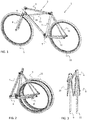
Figure 1 shows an axonometric representation of a foldable bicycle according to the present invention, -
Figure 2 shows a bicycle according toFigure 1 in folded state from the side, -
Figure 3 shows a bicycle according toFigure 2 in folded state from below, -
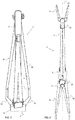
Figure 4 shows an axonometric representation of the frame of a foldable bicycle according to the present invention, -
Figure 5 shows a frame accordingFigure 4 from the front, -
Figure 6 shows a frame accordingFigure 4 from above, -
Figure 7 shows a frame joint at the head tube from the side, -
Figure 8 shows the frame joint at the seat tube from the side, -
Figure 9 shows the frame joint at a crankshaft bearing housing from the side, -
Figure 10 shows the frame joint at the seat tube from above, -
Figure 11 shows the frame joint at the seat tube in the folded state of the bicycle from the front, -
Figure 12 shows the frame joint at the head tube from the back, -
Figure 13 shows the frame joint at the crankshaft bearing housing from the front, -
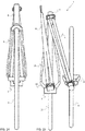
Figure 14 shows a bicycle in operational mode from the front, and -
Figure 15 shows a bicycle in folded state from the front. - The above figures do not show the bicycle in scale but are only intended to illustrate structural solutions of the preferred embodiments and the operation of the embodiments. Herein, the structural parts shown in the figures and denoted with reference numerals correspond to the structural solutions that are presented in the description below and are at the same time indicated by their reference numbers.
- As shown in
Figure 1 , thebicycle 1 comprises the usual main components. Thebicycle frame 2 is of the closed type, also referred to as diamond frame. It is made up of three frame tubes, in other words, aseat tube 3, adown tube 4 and atop tube 5 that form a rigid triangle structure. The top tube and down tube converge in ahead tube 6, while the seat tube and down tube converge in acrankshaft bearing housing 7. The top tube and seat tube join below the seat of the bicycle (not shown). From the head tube, afront fork 8 extends downward to be joined to afront wheel 9. From the opposite end of the head tube, a steering tube extends upward, to which handlebars are joined with a steering stem (not shown). - In the rear half of the bicycle, there is a
back fork 10, usually joined to theseat tube 3. The back fork is attached to aback wheel 11 and two chain stays 12 that extend out of thecrankshaft bearing housing 7. The seat tube partly surrounds a seat tube, to which the seat of the bicycle is arranged (not shown), while the crankshaft bearing housing has two pedal cranks with as many pedals (not shown). - In the present figures, the bicycle parts are shown as substantially round structural parts, but may also be oval or polygonal. The structural parts can be made as simple, double parallel parts or as a combination of these depending on the manufacturing material and required rigidity. The structural parts can be made of metal, various fiber materials or even wood. They may be hollow or compact depending on the material and cross-sectional form. For example,
Figure 5 , which is a front view of thebicycle 1, andFigure 6 , which is a top view of the bicycle, show that thetop tube 5 is made of two substantially parallel parts. The downtube 4 is, in turn, made as a Y tube that widens close to thecrankshaft bearing housing 7. - To stabilize the
frame 2 of the presentfoldable bicycle 1, it also has aninclined strut 13 that extends from thetop tube 5 to thedown tube 4. The inclined strut is arranged in a pivoted manner to the top tube while theconnection 14 to the down tube is arranged to be opened, i.e. the inclined strut can be detached from the down tube with a few simple movements. - The folding of a
bicycle 1 according to the present embodiment is possible through some specific structural solutions shown inFigure 4 . Firstly, thedown tube 4 comprises twoparts Figure 2 ). Thefront part 4a of the two-part down tube is rigidly joined with thehead tube 6, while therear part 4b of the down tube is joined in a pivoted manner to thecrankshaft bearing housing 7. The front and rear parts are joined with amechanical connection 15, for instance a screw joint shown inFigure 7 . - The above-mentioned
inclined strut 13 extends from thetop tube 5 to the two-part downtube 4 in such a manner that theconnection 14 to the down tube is arranged to be between thecrankshaft bearing housing 7 andconnection 15 that connects the front 4a and rear 4b parts of the down tube. In a specific embodiment, it is even possible that the inclined strut extends from the top tube to the two-part down tube in such a manner that the connection to the down tube is arranged to be in theconnection 15 that connects the front and rear parts of the down tube. - Secondly, the
rear part 4b of the down tube has a pivotedconnection 16, in which arotation axle 17 is on a plane perpendicular to thelongitudinal axis 18 of the rear part of the down tube, seeFigure 4 . The structure is also shown in detail inFigures 9 and13 . Therotation axle 17 of the pivotedconnection 16 is at the same time turned in the above-mentioned plane in such a manner that it is at an angle α against a line that is parallel to thelongitudinal axis 19 of thecrankshaft bearing housing 7, wherein the parallel line is marked by 19', seeFigure 13 . This angle is in the size range of 2 to 11 degrees, preferably 6 to 7 degrees. The turning preferably occurs counter-clockwise around thelongitudinal axis 18 as seen along the longitudinal axis toward the crankshaft bearing housing. The angling of therotation axle 17 of the joint 16 that connects therear part 4b of the down tube to thecrankshaft bearing housing 7 causes the part of the down tube to be moved in relation to theseat tube 3, when the down tube is folded during the folding of thebicycle 1. This is shown inFigure 15 , for instance. - Thirdly, the
top tube 5 has at one end thereof a pivotedconnection 20, where it connects with theseat tube 3, seeFigure 4 . The structure is also shown in detail inFigures 8 ,10, and 11 . Therotation axle 21 in this pivoted connection is substantially perpendicular to the longitudinal axis of theseat tube 22. At the same time, the rotation axle is turned around this longitudinal axis in such a manner that it is at an angle β that is in the size range of 7 to 23 degrees, preferably 13 to 17 degrees, in relation to thelongitudinal axis 23 of the top tube, seeFigure 10 . The turning preferably takes place clockwise around the seat tube as seen in a direction toward the crankshaft bearing housing. The essential thing herein is that therotation axle 21 of the top tube is turned around theseat tube 3 in a direction opposite to the turning of therotation axle 17 of therear part 4b of the down tube around thelongitudinal axis 18 of therear part 4b of the down tube, as seen in a direction toward thecrankshaft bearing housing 7. The angling of the rotation axle of the top tube means that the even the top tube will be moved in relation to theseat tube 3, when thetop tube 5 is folded down during the folding of thebicycle 1. Due to the different directions of eachrotation axle - Fourthly, the
top tube 5 has at its second end that is opposite the seat tube 3 a pivoted connection to thehead tube 6, seeFigure 4 . The structure is also shown in detail inFigure 7 . Therotation axle 21 in this pivotedconnection 25 is arranged to be substantially perpendicular to both the longitudinal axis of thehead tube 26 and thelongitudinal axis 23 of the top tube. Thanks to this joint, it is possible to fold the head tube-mountedfront fork 8 and thefront wheel 9 in it against theback wheel 11. With this last folding, the outer dimensions of the folded package can be minimized. - So as to further ensure that the path of movement of the
front wheel 9 does not, during the folding of thebicycle 1, coincide with any other structural parts of the bicycle, therotation axle 21 in the joint 20 between thetop tube 5 andseat tube 3 should preferably be allowed to be on a plane that is substantially parallel to the seat tube. The rotation axle can now be given a turn γ on this plane, which is in the size range of 2 to 9 degrees, preferably 5 to 6 degrees to the normal of thecross-sectional plane 27 of the bicycle, when it has followed the joint between the top tube and seat tube during its turning around the longitudinal axis of the seat tube, seeFigures 10 and 11 . The rotation takes place counter-clockwise, when the joint is seen along the top tube toward the seat tube. The same result can also be achieved by allowing therotation axle 24 in the joint 25 between thetop tube 5 andhead tube 6 instead to be on a plane that is substantially parallel to the head tube. After this, therotation axle 24 is allowed to turn on this plane to a corresponding angle δ, which is in the size range of 2 to 9 degrees, preferably 5 to 6 degrees, to the normal of thecross-sectional plane 27 of the bicycle, seeFigure 12 . The rotation takes place counter-clockwise, when the joint is seen along the top tube toward the head tube. A bicycle according to the present embodiment can be folded in a manner that is best shown inFigures 1 to 3 and14 and 15 . - First, the
connection 14 between theinclined strut 13 and downtube 4 is opened and the inclined strut is folded against thetop tube 5. Then, theconnection 15 that joins both parts of the down tube is opened. The freedrear part 4b of the down tube can now be rotated clockwise in relation to therotation axle 17 into a position beside theseat tube 3. The front half of the bicycle is now free to be rotated around therotation axle 21 against the rear half of the bicycle. - The
top tube 5 is rotated counter-clockwise around therotation axle 21 of the top tube toward theseat tube 3, where it takes a position beside the seat tube which is opposite that of theinclined strut 13. At the same time, thefront wheel 9 swings in a direction toward theback wheel 11. To finally set the front wheel against the back wheel, thehead tube 6 is rotated counter-clockwise around therotation axle 24. When the wheels are beside each other, their axles can preferably be locked to each other to, thus, stabilize the folded bicycle. By fastening the wheel axles to each other, it also becomes possible for the wheels to continue to roll freely on a base, which facilitates the transport of the folded bicycle. - The above description and the related figures are only intended to illustrate the present solution for the construction of a bicycle. Thus, the solution is not confined merely to the embodiments described above or in the attached claims but a plurality of variations or alternative embodiments is feasible within the idea described in the attached claims.
Claims (17)
- Bicycle (1), which bicycle especially comprises:a bicycle having a foldable structure witha frame (2) having a seat tube (3), an down tube (4), and a top tube (5) which form a rigid triangle structure, whereinthe top tube (5) and down tube (4) are connected to a head tube (6), whilethe seat tube (3) and down tube (4) are connected to a crankshaft bearing housing (7), andthe top tube and seat tube are joined below a seat of the bicycle, andthe bicycle (1) further has front and back wheels (9, 11) connected with the frame via a front fork (8) and rear fork (10),an inclined strut (13) extends from the top tube (5) to the down tube (4), which inclined strut is pivoted to the top tube, while the connection (14) to the down tube is arranged to be opened, andthe down tube (4) comprises two parts, whereby it comprises two parts (4a, 4bI) that are detachably attached to each other, andthe top tube (5) has at one end a pivoted connection to the seat tube (3) so that a rotation axle (21) in this joint (20) is substantially perpendicular to a longitudinal axis (23) in the seat tube, while the rotation axle (21) is turned around this longitudinal axis (23) to an angle (β) in relation to the longitudinal axis of the top tube, andthe rotation axle (21) of the joint (20) between the top tube (5) and seat tube (3) is on a plane substantially parallel to the seat tube and shows a turn (γ) on this plane, which is 2 to 9 degrees to the normal of the cross-sectional plane (27) of the bicycle, andthe top tube (5) has at its other end that is opposite the seat tube (3) is connected in a pivoted manner with the head tube (6) so that a rotation axle (24) in this joint (25) is substantially perpendicular to the longitudinal axes of both the head tube and top tube.
- A bicycle (1) as claimed in claim 1, wherein the rotation axle (21) shows a turn (γ) counter-clockwise to the normal of the cross-sectional plane (27) of the bicycle when
the rotation axle (21) in the joint (20) shows an angle (β) clockwise around the seat tube viewed in the direction of the crankshaft bearing housing. - A bicycle (1) as claimed in claim 1, wherein the rotation axle (21) shows a turn (γ) clockwise to the normal of the cross-sectional plane (27) of the bicycle when
the rotation axle (21) in the joint (20) shows an angle (β) counter-clockwise around the seat tube viewed in the direction of the crankshaft bearing housing. - A bicycle (1) as claimed in claim 1, wherein the down tube is connected in a pivoted manner to the crankshaft bearing housing (7) so that a rotation axle (17) in this joint (16) is on a plane that is perpendicular to a longitudinal axis (18) in the down tube (4) and the rotation axle (17) is simultaneously turned on said plane into an angle (α) in relation to a line (19') that is substantially parallel to the longitudinal axis (19) of the crankshaft bearing housing.
- A bicycle (1) as claimed in claim 1, wherein the down tube (4) comprises a front part (4a) that is joined rigidly to the head tube (6), and a rear part (4b) that has a pivoted connection with the crankshaft bearing housing (7).
- A bicycle (1) as claimed in claim 5, wherein the front and rear parts (4a, 4b) of the down tube (4) are joined with a mechanic connection (15),
- A bicycle (1) as claimed in claim 6, wherein the mechanical connection (15) is a screw connection.
- A bicycle (1) as claimed in claim 5, wherein the rotation axle (17) in the joint (16) between the down tube (4) and crankshaft bearing housing (7) is at an angle (α) to a line (19') that is parallel to the longitudinal axis (19) of the crankshaft bearing housing, which is 2 to 11 degrees.
- A bicycle (1) as claimed in claim 8, wherein the angle (α) is preferably 6 to 7 degrees.
- A bicycle (1) as claimed in claim 5, wherein the rotation axle (21) in the joint (20) between the top tube (5) and seat tube (3) is at an angle (β) to the longitudinal axis (23) of the top tube (5), which is 7 to 23 degrees.
- A bicycle (1) as claimed in claim 10, wherein the angle (β) is preferably 13 to 17 degrees.
- A bicycle (1) as claimed in claim 10, wherein the rotation axle (21) of the top tube (3) is turned toward the seat tube (3) in a direction opposite to the turning of the rotation axle (17) of the rear part (4b) of the down tube around the longitudinal axis (18) of the rear part (4b) of the down tube, as seen in a direction toward the crankshaft bearing housing (7).
- A bicycle (1) as claimed in claim 1, wherein the angle (γ) is preferably 5 to 6 degrees.
- A bicycle (1) as claimed in claim 12, wherein the rotation axle (24) in the joint (25) between the top tube (5) and head tube (6) is on a plane substantially parallel to the head tube and shows a turn (γ) on this plane, which is 2 to 9 degrees counter-clockwise to the normal of the cross-sectional plane of the bicycle.
- A bicycle as claimed in claim 14, wherein the angle (γ) is preferably 5 to 6 degrees.
- A bicycle (1) as claimed in claim 6, wherein the inclined strut (13) extends from the top tube (5) to the two-part down tube (4) in such a manner that the connection (14) to the down tube is arranged to be between the crankshaft bearing housing (7) and connection (15) that joins the front and rear parts (4a, 4b) of the down tube (4).
- A bicycle (1) as claimed in claim 16, wherein the inclined strut (13) extends from the top tube (5) to the two-part down tube (4) in such a manner that the connection (14) to the down tube is arranged to coincide with the connection (15) that joins the front and rear parts (4a, 4b) of the down tube.
Applications Claiming Priority (1)
| Application Number | Priority Date | Filing Date | Title |
|---|---|---|---|
| FI20165774A FI20165774A (en) | 2016-10-12 | 2016-10-12 | Bicycle |
Publications (2)
| Publication Number | Publication Date |
|---|---|
| EP3309050A1 true EP3309050A1 (en) | 2018-04-18 |
| EP3309050B1 EP3309050B1 (en) | 2020-09-16 |
Family
ID=60080630
Family Applications (1)
| Application Number | Title | Priority Date | Filing Date |
|---|---|---|---|
| EP17195709.5A Active EP3309050B1 (en) | 2016-10-12 | 2017-10-10 | Bicycle |
Country Status (3)
| Country | Link |
|---|---|
| EP (1) | EP3309050B1 (en) |
| CN (1) | CN107933790B (en) |
| FI (1) | FI20165774A (en) |
Cited By (1)
| Publication number | Priority date | Publication date | Assignee | Title |
|---|---|---|---|---|
| GB2608144A (en) * | 2021-06-23 | 2022-12-28 | Wilkinson Matthew | Foldable bicycle |
Families Citing this family (2)
| Publication number | Priority date | Publication date | Assignee | Title |
|---|---|---|---|---|
| FR3083203B1 (en) * | 2018-06-27 | 2020-08-14 | Look Cycle Int | BIKE FRAME |
| CN114313083B (en) * | 2022-01-27 | 2023-05-30 | 常州市华耀智能科技有限公司 | Foldable electric bicycle with hidden guide wheels in middle |
Citations (7)
| Publication number | Priority date | Publication date | Assignee | Title |
|---|---|---|---|---|
| GB2021055A (en) * | 1978-05-22 | 1979-11-28 | Herbert H G | Folding Cycle |
| EP0323964A1 (en) * | 1986-09-16 | 1989-07-19 | Sven Hellestam | Bicycle with a collapsible frame. |
| US5069468A (en) * | 1990-08-14 | 1991-12-03 | Tsai Shu Huey | Collapsible bicycle |
| CN2093806U (en) * | 1991-05-31 | 1992-01-22 | 蔡端慧 | Collapsible cycle |
| EP2409906A2 (en) * | 2010-07-21 | 2012-01-25 | Georg Mies | Folding bicycle |
| WO2012037798A1 (en) * | 2010-09-25 | 2012-03-29 | 大行科技(深圳)有限公司 | Foldable bicycle |
| CN204527468U (en) * | 2014-12-11 | 2015-08-05 | 托比亚.雷波西 | Folding bicycle |
Family Cites Families (9)
| Publication number | Priority date | Publication date | Assignee | Title |
|---|---|---|---|---|
| CN2343061Y (en) * | 1998-09-10 | 1999-10-13 | 颜育德 | Detachable bicycle frame |
| JP2001334979A (en) * | 2000-05-30 | 2001-12-04 | Miyata Ind Co Ltd | Foldaway bicycle |
| US6979013B2 (en) * | 2003-09-24 | 2005-12-27 | Giant Manufacturing Co., Inc. | Bicycle foldable to align front and rear wheels along a transverse direction of the bicycle |
| CN2815849Y (en) * | 2005-07-19 | 2006-09-13 | 高康桂 | Longitudinal-folding bicycle frame |
| FI20070192A0 (en) * | 2007-03-06 | 2007-03-06 | Ulf Laxstroem | Bicycle frame and bicycle |
| KR100981059B1 (en) * | 2010-02-09 | 2010-09-08 | 윤근수 | Folding bicycle |
| CN102358372A (en) * | 2011-09-06 | 2012-02-22 | 常州珍妮车业有限公司 | Frame assembly for foldable electric vehicle |
| CN102530162B (en) * | 2012-01-18 | 2013-09-04 | 眭华兴 | Portable foldable bicycle |
| CN202944503U (en) * | 2012-10-08 | 2013-05-22 | 吴宁 | Folding luggage barrow which can be unfolded to form bicycle |
-
2016
- 2016-10-12 FI FI20165774A patent/FI20165774A/en not_active Application Discontinuation
-
2017
- 2017-10-10 EP EP17195709.5A patent/EP3309050B1/en active Active
- 2017-10-12 CN CN201710946971.9A patent/CN107933790B/en active Active
Patent Citations (7)
| Publication number | Priority date | Publication date | Assignee | Title |
|---|---|---|---|---|
| GB2021055A (en) * | 1978-05-22 | 1979-11-28 | Herbert H G | Folding Cycle |
| EP0323964A1 (en) * | 1986-09-16 | 1989-07-19 | Sven Hellestam | Bicycle with a collapsible frame. |
| US5069468A (en) * | 1990-08-14 | 1991-12-03 | Tsai Shu Huey | Collapsible bicycle |
| CN2093806U (en) * | 1991-05-31 | 1992-01-22 | 蔡端慧 | Collapsible cycle |
| EP2409906A2 (en) * | 2010-07-21 | 2012-01-25 | Georg Mies | Folding bicycle |
| WO2012037798A1 (en) * | 2010-09-25 | 2012-03-29 | 大行科技(深圳)有限公司 | Foldable bicycle |
| CN204527468U (en) * | 2014-12-11 | 2015-08-05 | 托比亚.雷波西 | Folding bicycle |
Cited By (1)
| Publication number | Priority date | Publication date | Assignee | Title |
|---|---|---|---|---|
| GB2608144A (en) * | 2021-06-23 | 2022-12-28 | Wilkinson Matthew | Foldable bicycle |
Also Published As
| Publication number | Publication date |
|---|---|
| FI20165774A (en) | 2018-04-13 |
| CN107933790A (en) | 2018-04-20 |
| CN107933790B (en) | 2020-05-19 |
| EP3309050B1 (en) | 2020-09-16 |
Similar Documents
| Publication | Publication Date | Title |
|---|---|---|
| US10328992B2 (en) | Bicycle | |
| EP3309050B1 (en) | Bicycle | |
| US8894084B1 (en) | Compact folding bicycle | |
| US8328219B2 (en) | Bicycle frame and bicycle | |
| WO2002042148B1 (en) | Collapsible bicycle | |
| US20150291245A1 (en) | Leaning Tricycle | |
| US20080296862A1 (en) | Multi-mode tandem bicycle | |
| KR20120030859A (en) | Recumbent bike steering apparatus | |
| CN205707075U (en) | A kind of telescopic scooter of steering yoke | |
| US20090096187A1 (en) | Foldable jointed bicycle | |
| WO2012034158A1 (en) | Folding diamond type frame for a bicycle | |
| JP2009143339A (en) | Folding bicycle | |
| US10647376B2 (en) | Collapsible flip-pivot bicycle | |
| US20170259869A1 (en) | Tandem Bicycle | |
| US8757651B1 (en) | Collapsible motorized two-wheeled cycle system | |
| JP3150571U (en) | Folding bike | |
| JP6213272B2 (en) | Folding mechanism of handle part and folding bicycle | |
| US20240149969A1 (en) | Frame for multi-wheeled vehicle | |
| CN209833874U (en) | Folding mechanism for bicycle | |
| KR101011419B1 (en) | Collapsible bicycle | |
| WO2018163227A1 (en) | Foldable bicycle | |
| US20190291807A1 (en) | Foldable cycle assembly | |
| US509986A (en) | widerborg | |
| JPWO2019039500A1 (en) | Folding bicycle | |
| JPH0715493U (en) | Foldable bicycle |
Legal Events
| Date | Code | Title | Description |
|---|---|---|---|
| PUAI | Public reference made under article 153(3) epc to a published international application that has entered the european phase |
Free format text: ORIGINAL CODE: 0009012 |
|
| STAA | Information on the status of an ep patent application or granted ep patent |
Free format text: STATUS: THE APPLICATION HAS BEEN PUBLISHED |
|
| AK | Designated contracting states |
Kind code of ref document: A1 Designated state(s): AL AT BE BG CH CY CZ DE DK EE ES FI FR GB GR HR HU IE IS IT LI LT LU LV MC MK MT NL NO PL PT RO RS SE SI SK SM TR |
|
| AX | Request for extension of the european patent |
Extension state: BA ME |
|
| STAA | Information on the status of an ep patent application or granted ep patent |
Free format text: STATUS: REQUEST FOR EXAMINATION WAS MADE |
|
| 17P | Request for examination filed |
Effective date: 20181017 |
|
| RBV | Designated contracting states (corrected) |
Designated state(s): AL AT BE BG CH CY CZ DE DK EE ES FI FR GB GR HR HU IE IS IT LI LT LU LV MC MK MT NL NO PL PT RO RS SE SI SK SM TR |
|
| GRAP | Despatch of communication of intention to grant a patent |
Free format text: ORIGINAL CODE: EPIDOSNIGR1 |
|
| STAA | Information on the status of an ep patent application or granted ep patent |
Free format text: STATUS: GRANT OF PATENT IS INTENDED |
|
| INTG | Intention to grant announced |
Effective date: 20200407 |
|
| GRAS | Grant fee paid |
Free format text: ORIGINAL CODE: EPIDOSNIGR3 |
|
| GRAA | (expected) grant |
Free format text: ORIGINAL CODE: 0009210 |
|
| STAA | Information on the status of an ep patent application or granted ep patent |
Free format text: STATUS: THE PATENT HAS BEEN GRANTED |
|
| RAP1 | Party data changed (applicant data changed or rights of an application transferred) |
Owner name: LAXSTROEM, ZAKARIAS |
|
| RIN1 | Information on inventor provided before grant (corrected) |
Inventor name: LAXSTROEM, ZAKARIAS |
|
| AK | Designated contracting states |
Kind code of ref document: B1 Designated state(s): AL AT BE BG CH CY CZ DE DK EE ES FI FR GB GR HR HU IE IS IT LI LT LU LV MC MK MT NL NO PL PT RO RS SE SI SK SM TR |
|
| REG | Reference to a national code |
Ref country code: GB Ref legal event code: FG4D |
|
| REG | Reference to a national code |
Ref country code: CH Ref legal event code: EP |
|
| REG | Reference to a national code |
Ref country code: DE Ref legal event code: R096 Ref document number: 602017023653 Country of ref document: DE |
|
| REG | Reference to a national code |
Ref country code: IE Ref legal event code: FG4D |
|
| REG | Reference to a national code |
Ref country code: AT Ref legal event code: REF Ref document number: 1313943 Country of ref document: AT Kind code of ref document: T Effective date: 20201015 |
|
| PG25 | Lapsed in a contracting state [announced via postgrant information from national office to epo] |
Ref country code: BG Free format text: LAPSE BECAUSE OF FAILURE TO SUBMIT A TRANSLATION OF THE DESCRIPTION OR TO PAY THE FEE WITHIN THE PRESCRIBED TIME-LIMIT Effective date: 20201216 Ref country code: GR Free format text: LAPSE BECAUSE OF FAILURE TO SUBMIT A TRANSLATION OF THE DESCRIPTION OR TO PAY THE FEE WITHIN THE PRESCRIBED TIME-LIMIT Effective date: 20201217 Ref country code: NO Free format text: LAPSE BECAUSE OF FAILURE TO SUBMIT A TRANSLATION OF THE DESCRIPTION OR TO PAY THE FEE WITHIN THE PRESCRIBED TIME-LIMIT Effective date: 20201216 Ref country code: FI Free format text: LAPSE BECAUSE OF FAILURE TO SUBMIT A TRANSLATION OF THE DESCRIPTION OR TO PAY THE FEE WITHIN THE PRESCRIBED TIME-LIMIT Effective date: 20200916 Ref country code: SE Free format text: LAPSE BECAUSE OF FAILURE TO SUBMIT A TRANSLATION OF THE DESCRIPTION OR TO PAY THE FEE WITHIN THE PRESCRIBED TIME-LIMIT Effective date: 20200916 Ref country code: HR Free format text: LAPSE BECAUSE OF FAILURE TO SUBMIT A TRANSLATION OF THE DESCRIPTION OR TO PAY THE FEE WITHIN THE PRESCRIBED TIME-LIMIT Effective date: 20200916 |
|
| REG | Reference to a national code |
Ref country code: AT Ref legal event code: MK05 Ref document number: 1313943 Country of ref document: AT Kind code of ref document: T Effective date: 20200916 |
|
| REG | Reference to a national code |
Ref country code: NL Ref legal event code: MP Effective date: 20200916 |
|
| PG25 | Lapsed in a contracting state [announced via postgrant information from national office to epo] |
Ref country code: LV Free format text: LAPSE BECAUSE OF FAILURE TO SUBMIT A TRANSLATION OF THE DESCRIPTION OR TO PAY THE FEE WITHIN THE PRESCRIBED TIME-LIMIT Effective date: 20200916 Ref country code: RS Free format text: LAPSE BECAUSE OF FAILURE TO SUBMIT A TRANSLATION OF THE DESCRIPTION OR TO PAY THE FEE WITHIN THE PRESCRIBED TIME-LIMIT Effective date: 20200916 |
|
| REG | Reference to a national code |
Ref country code: LT Ref legal event code: MG4D |
|
| PG25 | Lapsed in a contracting state [announced via postgrant information from national office to epo] |
Ref country code: CZ Free format text: LAPSE BECAUSE OF FAILURE TO SUBMIT A TRANSLATION OF THE DESCRIPTION OR TO PAY THE FEE WITHIN THE PRESCRIBED TIME-LIMIT Effective date: 20200916 Ref country code: RO Free format text: LAPSE BECAUSE OF FAILURE TO SUBMIT A TRANSLATION OF THE DESCRIPTION OR TO PAY THE FEE WITHIN THE PRESCRIBED TIME-LIMIT Effective date: 20200916 Ref country code: PT Free format text: LAPSE BECAUSE OF FAILURE TO SUBMIT A TRANSLATION OF THE DESCRIPTION OR TO PAY THE FEE WITHIN THE PRESCRIBED TIME-LIMIT Effective date: 20210118 Ref country code: LT Free format text: LAPSE BECAUSE OF FAILURE TO SUBMIT A TRANSLATION OF THE DESCRIPTION OR TO PAY THE FEE WITHIN THE PRESCRIBED TIME-LIMIT Effective date: 20200916 Ref country code: EE Free format text: LAPSE BECAUSE OF FAILURE TO SUBMIT A TRANSLATION OF THE DESCRIPTION OR TO PAY THE FEE WITHIN THE PRESCRIBED TIME-LIMIT Effective date: 20200916 Ref country code: SM Free format text: LAPSE BECAUSE OF FAILURE TO SUBMIT A TRANSLATION OF THE DESCRIPTION OR TO PAY THE FEE WITHIN THE PRESCRIBED TIME-LIMIT Effective date: 20200916 |
|
| PG25 | Lapsed in a contracting state [announced via postgrant information from national office to epo] |
Ref country code: ES Free format text: LAPSE BECAUSE OF FAILURE TO SUBMIT A TRANSLATION OF THE DESCRIPTION OR TO PAY THE FEE WITHIN THE PRESCRIBED TIME-LIMIT Effective date: 20200916 Ref country code: AT Free format text: LAPSE BECAUSE OF FAILURE TO SUBMIT A TRANSLATION OF THE DESCRIPTION OR TO PAY THE FEE WITHIN THE PRESCRIBED TIME-LIMIT Effective date: 20200916 Ref country code: AL Free format text: LAPSE BECAUSE OF FAILURE TO SUBMIT A TRANSLATION OF THE DESCRIPTION OR TO PAY THE FEE WITHIN THE PRESCRIBED TIME-LIMIT Effective date: 20200916 Ref country code: PL Free format text: LAPSE BECAUSE OF FAILURE TO SUBMIT A TRANSLATION OF THE DESCRIPTION OR TO PAY THE FEE WITHIN THE PRESCRIBED TIME-LIMIT Effective date: 20200916 Ref country code: IS Free format text: LAPSE BECAUSE OF FAILURE TO SUBMIT A TRANSLATION OF THE DESCRIPTION OR TO PAY THE FEE WITHIN THE PRESCRIBED TIME-LIMIT Effective date: 20210116 |
|
| REG | Reference to a national code |
Ref country code: CH Ref legal event code: PL |
|
| REG | Reference to a national code |
Ref country code: DE Ref legal event code: R097 Ref document number: 602017023653 Country of ref document: DE |
|
| PG25 | Lapsed in a contracting state [announced via postgrant information from national office to epo] |
Ref country code: MC Free format text: LAPSE BECAUSE OF FAILURE TO SUBMIT A TRANSLATION OF THE DESCRIPTION OR TO PAY THE FEE WITHIN THE PRESCRIBED TIME-LIMIT Effective date: 20200916 Ref country code: LU Free format text: LAPSE BECAUSE OF NON-PAYMENT OF DUE FEES Effective date: 20201010 Ref country code: SK Free format text: LAPSE BECAUSE OF FAILURE TO SUBMIT A TRANSLATION OF THE DESCRIPTION OR TO PAY THE FEE WITHIN THE PRESCRIBED TIME-LIMIT Effective date: 20200916 |
|
| REG | Reference to a national code |
Ref country code: BE Ref legal event code: MM Effective date: 20201031 |
|
| PLBE | No opposition filed within time limit |
Free format text: ORIGINAL CODE: 0009261 |
|
| STAA | Information on the status of an ep patent application or granted ep patent |
Free format text: STATUS: NO OPPOSITION FILED WITHIN TIME LIMIT |
|
| 26N | No opposition filed |
Effective date: 20210617 |
|
| PG25 | Lapsed in a contracting state [announced via postgrant information from national office to epo] |
Ref country code: SI Free format text: LAPSE BECAUSE OF FAILURE TO SUBMIT A TRANSLATION OF THE DESCRIPTION OR TO PAY THE FEE WITHIN THE PRESCRIBED TIME-LIMIT Effective date: 20200916 Ref country code: DK Free format text: LAPSE BECAUSE OF FAILURE TO SUBMIT A TRANSLATION OF THE DESCRIPTION OR TO PAY THE FEE WITHIN THE PRESCRIBED TIME-LIMIT Effective date: 20200916 Ref country code: LI Free format text: LAPSE BECAUSE OF NON-PAYMENT OF DUE FEES Effective date: 20201031 Ref country code: BE Free format text: LAPSE BECAUSE OF NON-PAYMENT OF DUE FEES Effective date: 20201031 Ref country code: CH Free format text: LAPSE BECAUSE OF NON-PAYMENT OF DUE FEES Effective date: 20201031 |
|
| PG25 | Lapsed in a contracting state [announced via postgrant information from national office to epo] |
Ref country code: IT Free format text: LAPSE BECAUSE OF FAILURE TO SUBMIT A TRANSLATION OF THE DESCRIPTION OR TO PAY THE FEE WITHIN THE PRESCRIBED TIME-LIMIT Effective date: 20200916 Ref country code: IE Free format text: LAPSE BECAUSE OF NON-PAYMENT OF DUE FEES Effective date: 20201010 |
|
| PG25 | Lapsed in a contracting state [announced via postgrant information from national office to epo] |
Ref country code: TR Free format text: LAPSE BECAUSE OF FAILURE TO SUBMIT A TRANSLATION OF THE DESCRIPTION OR TO PAY THE FEE WITHIN THE PRESCRIBED TIME-LIMIT Effective date: 20200916 Ref country code: MT Free format text: LAPSE BECAUSE OF FAILURE TO SUBMIT A TRANSLATION OF THE DESCRIPTION OR TO PAY THE FEE WITHIN THE PRESCRIBED TIME-LIMIT Effective date: 20200916 Ref country code: CY Free format text: LAPSE BECAUSE OF FAILURE TO SUBMIT A TRANSLATION OF THE DESCRIPTION OR TO PAY THE FEE WITHIN THE PRESCRIBED TIME-LIMIT Effective date: 20200916 |
|
| PG25 | Lapsed in a contracting state [announced via postgrant information from national office to epo] |
Ref country code: MK Free format text: LAPSE BECAUSE OF FAILURE TO SUBMIT A TRANSLATION OF THE DESCRIPTION OR TO PAY THE FEE WITHIN THE PRESCRIBED TIME-LIMIT Effective date: 20200916 |
|
| PGFP | Annual fee paid to national office [announced via postgrant information from national office to epo] |
Ref country code: GB Payment date: 20221108 Year of fee payment: 6 Ref country code: FR Payment date: 20221130 Year of fee payment: 6 Ref country code: DE Payment date: 20221124 Year of fee payment: 6 |
|
| PG25 | Lapsed in a contracting state [announced via postgrant information from national office to epo] |
Ref country code: NL Free format text: LAPSE BECAUSE OF NON-PAYMENT OF DUE FEES Effective date: 20200923 |