EP3308978A1 - Fahrzeugluftreifen - Google Patents
Fahrzeugluftreifen Download PDFInfo
- Publication number
- EP3308978A1 EP3308978A1 EP17181603.6A EP17181603A EP3308978A1 EP 3308978 A1 EP3308978 A1 EP 3308978A1 EP 17181603 A EP17181603 A EP 17181603A EP 3308978 A1 EP3308978 A1 EP 3308978A1
- Authority
- EP
- European Patent Office
- Prior art keywords
- recess
- block element
- pneumatic tire
- cross
- section
- Prior art date
- Legal status (The legal status is an assumption and is not a legal conclusion. Google has not performed a legal analysis and makes no representation as to the accuracy of the status listed.)
- Granted
Links
Images


Classifications
-
- B—PERFORMING OPERATIONS; TRANSPORTING
- B60—VEHICLES IN GENERAL
- B60C—VEHICLE TYRES; TYRE INFLATION; TYRE CHANGING; CONNECTING VALVES TO INFLATABLE ELASTIC BODIES IN GENERAL; DEVICES OR ARRANGEMENTS RELATED TO TYRES
- B60C11/00—Tyre tread bands; Tread patterns; Anti-skid inserts
- B60C11/03—Tread patterns
- B60C11/032—Patterns comprising isolated recesses
- B60C11/0323—Patterns comprising isolated recesses tread comprising channels under the tread surface, e.g. for draining water
-
- B—PERFORMING OPERATIONS; TRANSPORTING
- B60—VEHICLES IN GENERAL
- B60C—VEHICLE TYRES; TYRE INFLATION; TYRE CHANGING; CONNECTING VALVES TO INFLATABLE ELASTIC BODIES IN GENERAL; DEVICES OR ARRANGEMENTS RELATED TO TYRES
- B60C11/00—Tyre tread bands; Tread patterns; Anti-skid inserts
- B60C11/03—Tread patterns
- B60C11/032—Patterns comprising isolated recesses
-
- B—PERFORMING OPERATIONS; TRANSPORTING
- B60—VEHICLES IN GENERAL
- B60C—VEHICLE TYRES; TYRE INFLATION; TYRE CHANGING; CONNECTING VALVES TO INFLATABLE ELASTIC BODIES IN GENERAL; DEVICES OR ARRANGEMENTS RELATED TO TYRES
- B60C11/00—Tyre tread bands; Tread patterns; Anti-skid inserts
- B60C11/03—Tread patterns
- B60C11/11—Tread patterns in which the raised area of the pattern consists only of isolated elements, e.g. blocks
-
- B—PERFORMING OPERATIONS; TRANSPORTING
- B60—VEHICLES IN GENERAL
- B60C—VEHICLE TYRES; TYRE INFLATION; TYRE CHANGING; CONNECTING VALVES TO INFLATABLE ELASTIC BODIES IN GENERAL; DEVICES OR ARRANGEMENTS RELATED TO TYRES
- B60C11/00—Tyre tread bands; Tread patterns; Anti-skid inserts
- B60C11/03—Tread patterns
- B60C11/13—Tread patterns characterised by the groove cross-section, e.g. for buttressing or preventing stone-trapping
- B60C11/1307—Tread patterns characterised by the groove cross-section, e.g. for buttressing or preventing stone-trapping with special features of the groove walls
-
- B—PERFORMING OPERATIONS; TRANSPORTING
- B29—WORKING OF PLASTICS; WORKING OF SUBSTANCES IN A PLASTIC STATE IN GENERAL
- B29D—PRODUCING PARTICULAR ARTICLES FROM PLASTICS OR FROM SUBSTANCES IN A PLASTIC STATE
- B29D30/00—Producing pneumatic or solid tyres or parts thereof
- B29D30/06—Pneumatic tyres or parts thereof (e.g. produced by casting, moulding, compression moulding, injection moulding, centrifugal casting)
- B29D30/72—Side-walls
- B29D2030/728—Decorating or marking the sidewalls after tyre vulcanization
-
- B—PERFORMING OPERATIONS; TRANSPORTING
- B60—VEHICLES IN GENERAL
- B60C—VEHICLE TYRES; TYRE INFLATION; TYRE CHANGING; CONNECTING VALVES TO INFLATABLE ELASTIC BODIES IN GENERAL; DEVICES OR ARRANGEMENTS RELATED TO TYRES
- B60C11/00—Tyre tread bands; Tread patterns; Anti-skid inserts
- B60C11/03—Tread patterns
- B60C11/12—Tread patterns characterised by the use of narrow slits or incisions, e.g. sipes
-
- B—PERFORMING OPERATIONS; TRANSPORTING
- B60—VEHICLES IN GENERAL
- B60C—VEHICLE TYRES; TYRE INFLATION; TYRE CHANGING; CONNECTING VALVES TO INFLATABLE ELASTIC BODIES IN GENERAL; DEVICES OR ARRANGEMENTS RELATED TO TYRES
- B60C11/00—Tyre tread bands; Tread patterns; Anti-skid inserts
- B60C11/03—Tread patterns
- B60C11/13—Tread patterns characterised by the groove cross-section, e.g. for buttressing or preventing stone-trapping
- B60C11/1307—Tread patterns characterised by the groove cross-section, e.g. for buttressing or preventing stone-trapping with special features of the groove walls
- B60C2011/133—Tread patterns characterised by the groove cross-section, e.g. for buttressing or preventing stone-trapping with special features of the groove walls comprising recesses
Definitions
- the present invention relates to a pneumatic tire with a profiled tread and with radially raised, separate profile block elements.
- the invention relates to a pneumatic tire with a profiled tread with radially raised, separate profile block elements.
- At least one profile block element has at least one recess on a side surface of the profile block element.
- the recess for influencing mechanical properties of the at least one profile block element is provided.
- the mechanical properties of the at least one profile block element are, in particular, a compression modulus or an elasticity of the at least one profile block element.
- the side surface of the tread block element extends obliquely or perpendicular to a road contact surface of the tread block element.
- the road contact surface is the surface of the tread block element, which in a regular unwinding of the tire is in direct contact with the roadway on which the pneumatic tire rolls.
- the side surface of the tread block element extends in particular radially from the tread path leading and perpendicular to a rotational axis of the pneumatic tire.
- the pneumatic tires having tread block elements.
- the profile block elements for example, recesses on the side surfaces.
- T2 discloses a tread for pneumatic tires, wherein the tread has relief elements having at least one side surface.
- at least one relief element has lateral openings, wherein the lateral openings pass through the relief element.
- the known from the prior art method for producing the recesses may be limited in terms of a configuration of the recess.
- the methods known from the prior art are limited in terms of the dimensions of the recesses produced.
- the background to this limitation is that only certain minimum cuts or minimum removal on the side surface of a profile block element can be made by means of the method known from the prior art, which is only carried out mechanically in order to produce recesses.
- the fact that only certain minimum cuts or minimum abrasions can be made on the side surface of a tread block element may limit the ability to create certain, possibly complex, shapes of a cross-section of the recess.
- An effect of the recess on the profile block element may depend in particular on the nature of the recess.
- the effect that the recess is to exert on the tread block element for example, relates to the elasticity or the compressibility of the tread block element.
- the more diverse the possibilities of the design of the recess the more diverse the influence on the properties of the profile block element can be taken. Since the possibilities for forming the geometry and the dimensions according to the prior art are limited, thus also the possibilities of influencing the properties of the profile block element can be limited. This can lead to the use of the profile block elements is not optimally designed.
- the invention is therefore based on the object to provide improved profile block elements.
- a recess which has been produced by means of a laser has in particular a surface which has parallel elongated depressions, the depressions each having a width of between 0.1 mm and 1 mm.
- a recess can be produced by means of a laser, which has smaller dimensions compared to mechanically generated recesses. Due to the fact that the recesses can have a higher number of different geometries and, moreover, can have smaller dimensions than in the prior art, a varied and targeted influence on the mechanical properties of a profile block element can be taken.
- the specific influence can be achieved, for example, by producing the recesses only in certain areas of the side surface of the profiled block element, this is possible because the recesses have smaller dimensions than has hitherto been known from the prior art. Due to the diverse and targeted influence on the properties of a profile block element, the use of the profile block element itself can be improved.
- the tread block element can in particular be reliably designed for specific road conditions, for example an icy roadway. Overall, an improved profile block element is thus provided.
- the further properties of the tread block element include, for example, a rolling resistance of the tread in connection with the tread block element.
- the at least one recess has been produced by means of a pulsed laser.
- the quantities of rubber cut out of the pneumatic tire by the laser and thus the dimensions of a recess can be set very precisely.
- a variety of geometric shapes of the recesses can be generated. The background is that with a pulsed laser, the energy used to cut out material from the tread block element and the time duration of this cutting out can be set exactly.
- a minimum extension of a surface of a cross section of the at least one recess is 0.05 mm to 0.1 mm.
- the cross section is in particular the cross section of a recess which is aligned orthogonal to a longitudinal alignment of the recess by the profile block element.
- the longitudinal alignment corresponds in particular to the alignment of the recess in the tread block element, which is parallel or orthogonal to a circumferential direction of the pneumatic tire and each perpendicular to its axis of rotation.
- recesses can be provided in which only very small amounts of the tread block element has been cut out.
- complex geometric shapes can be produced in particular.
- the cross section of the at least one recess in the profile block element varies.
- the rigidity within a tread block element can be accurately and specifically generated.
- the areas that are closer to a surface of the tread block element may be referred to as edge areas.
- the areas of the tread block element that are not edge areas may be referred to as interior areas.
- the interior areas are surrounded by the border areas; the edge areas are spatially between the surfaces of the tread block element and the interior areas.
- At least one first recess is connected via a channel with at least one other recess within the profile block element.
- the circumstance according to the invention can further influence the properties of a profile block element.
- the at least one first recess which is connected via a channel with at least one other recess within the tread block element, may be arranged on an upper region of the tread block element oriented towards the roadway.
- a tread block element is provided which has an improved driving behavior, in particular on a wet roadway or on an icy roadway.
- the at least one recess has a depth in the profile block element which corresponds to 30% to 100% and in particular 50% to 100% of the length of an extension of the at least one profile block element.
- the circumstance according to the invention according to which the at least one recess has a depth in the profile block element which corresponds to 30% to 100% and in particular 50% to 100% of the length of an extension of the at least one profile block element, optimizes a pressure distribution in the profile block element.
- a uniform abrasion of the tread block element is ensured in this way.
- the recesses protrude into the profile block element, but only form an opening of the profile block element on one side surface, it is possible to influence the pressure distribution on the profile block element in a targeted manner.
- the number of recesses in at least one profile block element is at least 1, 2, 3, 4, 5, 6, 7, 8, 9, 10 or up to 200.
- a first recess extends along a first direction within the at least one tread block element. Furthermore, a second recess extends along a second direction of the at least one profile block element.
- the at least one first recess with the at least one second recess forms an angle of 0 ° to 90 ° and preferably from 0 ° to 45 °.
- the at least one recess has a generally concave-polygonal shape of the cross-section, a generally overturned-polygonal shape of the cross-section, an equilateral concave-polygonal shape of the cross-section, an equilateral overlapping-polygonal shape of the cross-section, an equiangular overlap Polygonal shape of the cross section or a regularly overlapped-polygonal shape of the cross section or a regular convex-polygonal shape of the cross section.
- At least one profile block element has at least one first recess with a shape of the cross section according to the previously described embodiment and at least the same profile block element has another recess with the same or with another shape of the cross section according to the embodiment described above.
- a number of the corners of the polygonal shape of the cross section is 3, 4, 5, 6, 7, 8 or 9.
- a hexagonal shape of the cross section is preferred.
- a direction in which a recess extends within a tread block element forms an angle of 0 ° to 10 ° with a road contact surface of the tread block element.
- At least one recess is formed exclusively in a base region of the at least one profile block element.
- at least one recess is formed exclusively in a head region of the at least one profile block element.
- a base region of the at least one tread block element is one such region of the tread block element that faces the tread of the pneumatic tire is oriented.
- the head region of the at least one profile block element is such an area of the at least one profile block element that is oriented toward a possible roadway.
- the head region points away from the tread in the radial direction.
- the base region is spatially arranged between the head region and the tread of the pneumatic tire.
- the recesses Due to the fact that the recesses are formed only in a base region or in a head region, it is possible to influence the compressibility of the profile block element. The further the recesses are arranged only in the area of the head area, the higher is the compressibility. In addition, with abrasion effects on the profiled block element, it may happen that the recesses are exposed, in which case an enlarged outer surface of the profiled block element would result which leads to changed driving characteristics of the profiled block element. This may be useful in certain road conditions, for example, in a wet or ice-covered roadway. An arrangement of the recesses of the recesses only in a base region leads to an improved braking behavior of the profile block element. Moreover, in this case the exclusive arrangement in the base region does not affect the recesses of abrasion effects on the tread block element itself.
- the extension of the at least one recess in the at least one tread block element extends parallel or orthogonal to a circumferential direction of the pneumatic tire.
- a next preferred embodiment of the invention is a first extension of a cross section of at least one recess to a second extension of the cross section of the at least one recess in an aspect ratio of at least 1: 2.
- the first extension extends radially away from the tread and perpendicular to a rotational axis of the pneumatic tire.
- the second extent extends parallel to a circumferential direction of the pneumatic tire or parallel to a rotational axis of the pneumatic tire.
- the second extent extends in particular orthogonal to the first extent.
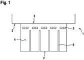
- FIG. 1 is a portion of a pneumatic tire according to the invention according to a first embodiment shown schematically in radial section view.
- the pneumatic tire 1 has a tread 2.
- the profiled tread 2 on radially raised, separate profile block elements 3.
- at least one profile block element 3 on a side surface 4 of the profile block element 3 at least one Recess 5 on.
- the recess 5 is provided for influencing the mechanical properties, in particular of a compression module, of the at least one profile block element 3.
- the at least one recess 5 has been produced by means of a laser.
- the profile block element 3 has, in particular, cuts 6 in the profile block element 3.
- the incisions 6 lead to the formation of a lamellar structure of the tread block element 3.
- F denotes a road contact surface of the tread block element 3.
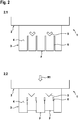
- FIG. 2 a region of a pneumatic tire according to the invention 1 according to a second embodiment is shown schematically in radial section view.
- the recess 5 is designed V-shaped.
- Part Figure 2.1 shows the tread block element 3 in a state without such a pressure acting on the tread block element 3, which leads to a deformation of the tread block element 3.
- subfigure 2.2 a pressure acts on the profile block element 3 which leads to a deformation of the profile block element 3.
- the pressure acts in the direction of R1 on the profile block element 3.
- the recesses 5 are pressed together.
- the in the FIG. 2 illustrated embodiment of the tread block element 3 ensures particularly good braking properties of the tread block element 3.
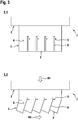
- FIG. 3 is a portion of a pneumatic tire according to the invention 1 according to a third embodiment shown schematically in radial section view.
- the recess 5 is wedge-shaped.
- Part 3.1 shows the tread block element 3 in a state without such a pressure acting on the tread block element 3, which leads to a deformation of the tread block element 3.
- part figure 3.2 a pressure on the profile block element 3 which leads to a deformation of the profile block element 3 acts.
- the pressure acts in the direction of R1 on the profile block element 3.
- the recesses 5 are pressed together.
- the lamellar regions of the tread block element 3 generated by the incisions 6 rotate in the direction R2.
- the in the FIG. 3 illustrated embodiment of the tread block element 3 provides good driving characteristics of the tread block element 3, especially in the case of a snow-covered or ice-covered road safely.
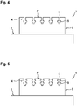
- FIG. 4 is a portion of a pneumatic tire according to the invention 1 according to a fourth embodiment shown schematically in radial section view.
- the respective recess 5 designed such that it is connected to the respective recess 6.
- FIG. 5 a region of a pneumatic tire according to the invention 1 according to a fifth embodiment is shown schematically in radial section view. Unlike the one in the FIG. 4 schematically illustrated embodiment, at least two recesses 5 are each configured such that they are connected to the respective incision 6.
- FIG. 6 is a portion of a pneumatic tire according to the invention 1 according to a sixth embodiment shown schematically in radial section view.
- the recesses 5 for example, a circular cross-section.
- the embodiment shown in this figure is not limited to this cross section.
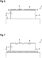
- the recesses 5 are formed such that they are arranged exclusively in a head region 8 of the profile block element 3. This embodiment ensures high compressibility of the profile block element 3.
- FIG. 7 is a portion of a pneumatic tire according to the invention 1 according to a seventh embodiment shown schematically in radial section view.
- the recesses 5 for example, a circular cross-section.
- the embodiment shown in this figure is not limited to this cross section.
- the recesses 5 are formed such that they are arranged exclusively in a base region 9 of the profile block element 3. This embodiment ensures a good braking property of the tread block element 3.
- FIG. 8 is an area of a pneumatic tire according to the invention 1 according to an eighth embodiment shown schematically in a sectional perspective.
- the recesses 5.1 and 5.2 different lengths.
- the in the FIG. 8 schematically illustrated embodiment leads in comparison to the profile block elements, which are known from the prior art, in particular to an optimized pressure distribution in the profile block element 3 and to an optimized abrasion of the profile block element. 3
- FIG. 9 a region of a pneumatic tire according to the invention 1 according to a ninth embodiment is shown schematically in a sectional perspective.
- the recesses are 5.3 and 5.4 connected via a channel 7 with each other.
- Channel 7 is permeable to liquids and gases.
- the channel 7 has preferably been produced by means of a laser.
- FIG. 10 a region of a pneumatic tire 1 according to the invention according to a tenth embodiment is shown schematically in a sectional perspective.
- At least one second recess 5.6 extends along a second direction of the at least one profile block element 3.
- the at least one first recess 5.5 forms with the at least a second recess 5.6 an angle of 0 ° to 45 °.
- the fact that the at least one first recess 5.5 forms an angle of 0 ° to 45 ° with the at least one second recess 5.6 leads in particular to anisotropic properties of the at least one profile block element 3, for example with regard to compressibility or abrasion of the at least one profile block element 3 ,
- FIG. 11 Possible shapes of a cross-section Q of the recess 5 in the side surface 4 of a tread block element 3 on a pneumatic tire 1 according to the invention are shown schematically.
- Sub-figure 11.1 shows a generally convex-polygonal shape of the cross-section Q.
- Sub-figure 11.2 shows a generally concave-polygonal shape of the cross-section Q.
- Sub-figure 11.3 shows a generally flipped-polygonal shape of the cross-section Q.
- Sub-figure 11.4 shows an equilateral convex-polygonal shape of the cross section
- Part 11.6 shows an equilateral concave-polygonal shape of the cross-section Q.
- Part 11.6 shows an equilateral-polygonal shape of the cross-section Q.
- Part 11.7 shows an equiangularly convex shape of the cross-section Q.
- Part 11.8 shows an equiangularly flipped shape of the cross-section Q.
- Sub-figure 11.9 shows a regular convex-triangular shape of the cross section Q.
- Sub-figure 11.10 shows a regular convex-quadratic shape of the cross-section Q.
- Sub-figure 11.11 shows a regular convex-pentagonal shape of the cross-section Q.
- Sub-figure 11.12 shows a regularly flipped shape of the cross-section Q.
- Part figure 11.13 zei gt a circular shape of the cross section Q.
- Part figure 11.14 shows an elliptical shape of the cross section.
- a first extent A1 of the cross section Q of at least one recess 5 to a second extent A2 of the cross section Q of the at least one recess 5 is in an aspect ratio of at least 1: 2.
- the first extent A1 extends radially away from the tread 2 and perpendicular to a rotational axis of the pneumatic tire 1.
- the second extent A2 extends parallel to a circumferential direction of the pneumatic tire 1 or parallel to a rotational axis of the pneumatic tire 1.
- Part figure 11.15 shows a rectangular shape of the cross section Q.
- Part Figure 11.16 shows a V-shape of the cross-section Q.
- Part figure 11.17 shows a wedge shape of the cross section Q.
- FIG. 12 is an inventive pneumatic tire 1 is shown schematically in radial section view.
- the Indian FIG. 12 schematically illustrated pneumatic tire 1 exemplifies a pneumatic tire whose areas in the FIGS. 1 . 2 . 3 . 4 . 5 . 6 . 7 . 8, 9 or 10 are shown schematically.
- An area of the pneumatic tire 1 shown in these figures schematically represents, for example, a tread block element 3 of the pneumatic tire FIG. 12
- the profile block elements 3 shown in these figures are therefore for example arranged on the tread 2 of the pneumatic tire 1.
- the in the FIG. 11 schematically illustrated shapes of the cross section Q of the recess 5 in the side surface 4 of a tread block element 3 can also on the pneumatic tire 1 according to the invention according to the FIG. 12 be generated.
- the radial sectional view of the pneumatic tire 1 of FIG. 12 refers to a rotation axis RA.
- the pneumatic tire 1 rotates in the direction of rotation U about the axis of rotation
- FIG. 13 For example, an exemplary surface 13 of a recess 5 in a tread block element 3, which has been made by means of a laser, is shown.
- the surface 13 has parallel elongated depressions 10.
- the depressions 10 each have a width 11 between 0.1 mm to 1 mm.
- the width 11 extends at right angles to the extension direction 12 of the depressions 10.
- Such a surface 13 of a recess 5 is produced in particular by means of a pulsed laser.
Landscapes
- Engineering & Computer Science (AREA)
- Mechanical Engineering (AREA)
- Tires In General (AREA)
Abstract
Description
- Die vorliegende Erfindung bezieht sich auf einen Luftreifen mit einem profilierten Laufstreifen und mit radial erhabenen, voneinander getrennten Profilblockelementen.
- Die Erfindung geht aus von einem Luftreifen mit einem profilierten Laufstreifen mit radial erhabenen, voneinander getrennten Profilblockelementen. Dabei weist mindestens ein Profilblockelement an einer Seitenfläche des Profilblockelementes mindestens eine Aussparung auf. Dabei ist die Aussparung zur Beeinflussung mechanischer Eigenschaften des mindestens einen Profilblockelementes vorgesehen.
- Bei den mechanischen Eigenschaften des mindestens einen Profilblockelementes handelt es sich insbesondere um ein Kompressionsmodul oder eine Elastizität des mindestens einen Profilblockelementes.
- Die Seitenfläche des Profilblockelementes erstreckt sich schräg oder senkrecht zu einer Fahrbahnkontaktfläche des Profilblockelements. Die Fahrbahnkontaktfläche ist die Oberfläche des Profilblockelementes, die bei einem regulären Abrollen des Luftreifens in unmittelbarem Kontakt mit der Fahrbahn steht, auf der der Luftreifen abrollt.
Die Seitenfläche des Profilblockelementes erstreckt sich insbesondere radial von dem Laufstreifen wegweisend und rechtwinklig zu einer Rotationsachse des Luftreifens. - Aus dem Stand der Technik sind Luftreifen bekannt, wobei die Luftreifen Profilblockelemente aufweisen. Dabei weisen die Profilblockelemente beispielsweise Aussparungen an den Seitenflächen auf.
- So wird in der
DE 602 13 445 T2 eine Laufstreifen für Luftreifen offenbart, wobei der Laufstreifen Reliefelemente aufweist, die mindestens eine Seitenfläche besitzen. Dabei weist mindestens ein Reliefelement seitliche Öffnungen auf, wobei die seitlichen Öffnungen durch das Reliefelement hindurch gehen. - Die aus dem Stand der Technik bekannten Verfahren zur Erzeugung der Aussparungen können hinsichtlich einer Ausgestaltung der Aussparung begrenzt sein. Insbesondere sind die aus dem Stand der Technik bekannten Verfahren hinsichtlich der erzeugten Abmessungen der Aussparungen begrenzt. Hintergrund dieser Begrenzung ist, dass mittels der aus dem Stand der Technik bekannten, lediglich mechanisch durchgeführten Verfahren zur Erzeugung von Aussparungen nur bestimmte minimale Schnitte oder minimale Abtragungen an der Seitenfläche eines Profilblockelements vorgenommen werden können. Durch den Umstand, dass nur bestimmte minimale Schnitte oder minimale Abtragungen an der Seitenfläche eines Profilblockelements vorgenommen werden können, kann die Möglichkeit begrenzt sein, bestimmte, gegebenenfalls komplexe Formen eines Querschnitts der Aussparung zu erzeugen.
Eine Wirkung der Aussparung auf das Profilblockelement kann insbesondere von der Art der Aussparung abhängen. Die Wirkung, die die Aussparung auf das Profilblockelement ausüben soll, betrifft beispielsweise die Elastizität oder die Kompressibilität des Profilblockelements. Je vielfältiger die Möglichkeiten der Gestaltung der Aussparung sind, auf desto vielfältigere Weise kann auf die Eigenschaften des Profilblockelements Einfluss genommen werden. Da die Möglichkeiten zur Ausbildung der Geometrie und der Abmessungen gemäß dem Stand der Technik begrenzt sind, können somit auch die Möglichkeiten der Einflussnahme auf die Eigenschaften des Profilblockelementes begrenzt sein. Dies kann dazu führen, dass der Einsatz der Profilblockelemente nicht optimal gestaltet ist. - Der Erfindung liegt daher die Aufgabe zugrunde, verbesserte Profilblockelemente bereitzustellen.
- Gelöst wird die gestellte Aufgabe erfindungsgemäß dadurch, dass die mindestens eine Aussparung mittels eines Lasers hergestellt worden ist.
Eine Aussparung, die mittels eines Lasers hergestellt worden ist, weist insbesondere eine Oberfläche auf, die parallel verlaufende längliche Vertiefungen aufweist, wobei die Vertiefungen je eine Breite zwischen 0,1 mm bis 1 mm aufweisen. - Durch den erfindungsgemäßen Umstand, wonach die mindestens eine Aussparung mittels eines Lasers hergestellt worden ist, können Aussparungen an den Seitenflächen der Profilblockelemente erzeugt werden, bei denen eine, verglichen mit dem Stand der Technik, höhere Zahl verschiedener geometrischer Formen möglich ist. Darüber hinaus kann mittels eines Lasers eine Aussparung erzeugt werden, die im Vergleich zu mechanisch erzeugten Aussparungen kleinere Abmessungen aufweist. Durch den Umstand, dass die Aussparungen eine höhere Zahl verschiedener Geometrien aufweisen können und darüber hinaus kleinere Abmessungen als im Stand der Technik aufweisen können, kann vielfältiger und gezielter Einfluss auf die mechanischen Eigenschaften eines Profilblockelementes genommen werden. Der gezielte Einfluss kann beispielsweise dadurch erreicht werden, dass die Aussparungen nur in bestimmten Bereichen der Seitenfläche des Profilblockelements erzeugt werden, dies ist möglich, da die Aussparungen kleinere Abmessungen aufweisen, als es bislang aus dem Stand der Technik bekannt ist. Durch die vielfältige und gezielte Einflussnahme auf die Eigenschaften eines Profilblockelementes kann der Einsatz des Profilblockelementes selbst verbessert werden. Das Profilblockelement kann insbesondere zuverlässig für bestimmte Fahrbahngegebenheiten, beispielsweise eine vereiste Fahrbahn, ausgelegt werden. Insgesamt wird somit ein verbessertes Profilblockelement bereitgestellt. Zu den weiteren Eigenschaften des Profilblockelements gehört beispielsweise ein Rollwiderstand des Laufstreifens in Verbindung mit dem Profilblockelement.
- Weitere vorteilhafte Ausgestaltungsformen der Erfindung sind Gegenstand der Unteransprüche.
- Gemäß einer vorzugsweisen Ausgestaltungsform der Erfindung ist die mindestens eine Aussparung mittels eines gepulsten Lasers hergestellt worden.
- Durch den erfindungsgemäßen Umstand, wonach die mindestens eine Aussparung mittels eines gepulsten Lasers hergestellt worden ist, können die Mengen des Kautschuks, die mit dem Laser aus dem Luftreifen herausgeschnitten werden, und damit die Abmessungen einer Aussparung sehr genau eingestellt werden. Darüber hinaus kann eine Vielzahl geometrischer Formen der Aussparungen erzeugt werden. Hintergrund ist, dass mit einem gepulsten Laser die zum Herausschneiden von Material aus dem Profilblockelement verwendete Energie sowie die zeitliche Dauer dieses Herausschneidens exakt eingestellt werden kann.
- Gemäß einer nächsten vorzugsweisen Ausgestaltungsform der Erfindung beträgt eine minimale Ausdehnung einer Fläche eines Querschnitts der mindestens einen Aussparung 0,05 mm bis 0,1 mm.
Dabei handelt es sich bei dem Querschnitt insbesondere um den Querschnitt einer Aussparung, der orthogonal zu einer Längsausrichtung der Aussparung durch das Profilblockelement ausgerichtet ist. Die Längsausrichtung entspricht insbesondere der Ausrichtung der Aussparung in dem Profilblockelement, die parallel oder orthogonal zu einer Umlaufrichtung des Luftreifens und jeweils rechtwinklig zu seiner Rotationsachse liegt. - Durch den erfindungsgemäßen Umstand, wonach die eine minimale Ausdehnung einer Fläche eines Querschnitts, der mindestens einen Aussparung 0,05 mm bis 0,1 mm beträgt, können Aussparungen bereitgestellt werden, bei denen nur sehr geringe Mengen des Profilblockelementes herausgeschnitten worden ist. Zugleich können insbesondere auch komplexe geometrische Formen hergestellt werden. Dadurch, dass nur sehr geringe Mengen herausgeschnitten werden kann ein Einfluss auf die mechanischen Eigenschaften des Profilblockelements genommen werden, ohne, dass es zu einer Verschlechterung des Profilblockelements aufgrund einer zu großen weggeschnittenen Menge kommen kann.
- Die Einflussnahme auf das Profilblockelement ist dann durch die Position der Aussparung im Profilblockelement und die Geometrie der Aussparung hinreichend sichergestellt.
- Gemäß einer nächsten vorzugsweisen Ausgestaltungsform der Erfindung variiert der Querschnitt der mindestens einen Aussparung im Profilblockelement. Durch die Variation des Querschnitts der mindestens einen Aussparung im Profilblockelement kann die Steifigkeit innerhalb eines Profilblockelements genau und gezielt erzeugt werden. So kann beispielswiese an Bereichen des Profilblockelements die näher an einer Oberfläche angeordnet sind eine andere Steifigkeit erzeugt werden als in anderen Bereichen. Die Bereiche, die näher an einer Oberfläche des Profilblockelements liegen, können als Randbereiche bezeichnet werden. Die Bereiche des Profilblockelements, die keine Randbereiche sind, können als Innenbereiche bezeichnet werden. Die Innenbereiche werden von den Randbereichen umgeben; die Randbereiche liegen räumlich zwischen den Oberflächen des Profilblockelements und den Innenbereichen.
- Gemäß einer nächsten vorzugsweisen Ausgestaltungsform der Erfindung ist mindestens eine erste Aussparung über einen Kanal mit mindestens einer anderen Aussparung innerhalb des Profilblockelementes verbunden.
- Durch den erfindungsgemäßen Umstand, wonach mindestens eine erste Aussparung über einen Kanal mit mindestens einer anderen Aussparung innerhalb des Profilblockelementes verbunden ist, kann weiter Einfluss auf die Eigenschaften eines Profilblockelementes genommen werden. Beispielsweise kann die mindestens eine erste Aussparung, die über einen Kanal mit mindestens einer anderen Aussparung innerhalb des Profilblockelementes verbunden ist, an einem oberen zur Fahrbahn hin orientierten Bereich des Profilblockelementes angeordnet sein. Dadurch wird ein Profilblockelement bereitgestellt, das insbesondere bei einer nassen Fahrbahn oder bei einer vereisten Fahrbahn ein verbessertes Fahrverhalten aufweist. Hintergrund des günstigen Fahrverhaltens ist, dass bei einem gegebenenfalls erfolgten Abrieb oberer, zu einer Fahrbahn hinweisender Schichten des Profilblockelementes durch die beiden Aussparungen, die über einen Kanal verbunden sind, ein Abflusssystem für eventuell auftretendes Eiswasser erzeugt werden kann. Die Ableitung eventuell auftretenden Eiswassers führt unter anderem zu einer Verbesserung der Bremseigenschaften eines Profilblockelements. Dies führt zu einer Verbesserung des Bremsverhaltens des Luftreifens.
- Gemäß einer nächsten vorzugsweisen Ausgestaltungsform der Erfindung weist die mindestens eine Aussparung eine Tiefe im Profilblockelement auf, die 30% bis 100% und insbesondere 50% bis 100% der Länge einer Ausdehnung des mindestens einen Profilblockelementes entspricht.
Durch den erfindungsgemäßen Umstand, wonach die mindestens eine Aussparung eine Tiefe im Profilblockelement aufweist, die 30% bis 100% und insbesondere 50% bis 100% der Länge einer Ausdehnung des mindestens einen Profilblockelementes entspricht, eine Druckverteilung in dem Profilblockelement optimiert. Darüber hinaus wird ein gleichmäßiger Abrieb des Profilblockelements auf dieses Weise sichergestellt.
Für den Fall, dass die Aussparungen in das Profilblockelement hineinragen, aber nur an einer Seitenfläche eine Öffnung des Profilblockelements ausbilden, kann gezielt Einfluss auf die Druckverteilung auf dem Profilblockelement genommen werden. - Gemäß einer nächsten vorzugsweisen Ausgestaltungsform der Erfindung beträgt die Anzahl der Aussparungen in mindestens einem Profilblockelement mindestens 1,2, 3, 4, 5, 6, 7, 8, 9, 10 oder bis 200.
- Gemäß einer nächsten vorzugsweisen Ausgestaltungsform der Erfindung erstreckt sich eine erste Aussparung entlang einer ersten Richtung innerhalb des mindestens einen Profilblockelementes. Ferner erstreckt sich eine zweite Aussparung entlang einer zweiten Richtung des mindestens einen Profilblockelementes. Dabei bildet die mindestens eine erste Aussparung mit der mindestens einen zweiten Aussparung einen Winkel von 0° bis 90° und vorzugsweise von 0° bis 45°. Durch den erfindungsgemäßen Umstand, wonach die mindestens eine erste Aussparung mit der mindestens einen zweiten Aussparung einen Winkel von 0° bis 90° und vorzugsweise von 0° bis 45° bildet, werden eine optimale Blocksteifigkeit und eine optimale Kompressibilität des mindestens einen Profilblockelementes bewirkt.
- Gemäß einer nächsten vorzugsweisen Ausgestaltungsform der Erfindung weist die mindestens eine Aussparung allgemein konkav-polygonale Form des Querschnitts, eine allgemein überschlagen-polygonale Form des Querschnitts, eine gleichseitig konkav-polygonale Form des Querschnitts, eine gleichseitig überschlagen-polygonale Form des Querschnitts, eine gleichwinklig überschlagen-polygonale Form des Querschnitts oder eine regelmäßig überschlagen-polygonale Form des Querschnitts oder eine regelmäßig konvex-polygonale Form des Querschnitts auf.
- Gemäß einer nächsten vorzugsweisen Ausgestaltungsform der Erfindung weist mindestens ein Profilblockelement mindestens eine erste Aussparung mit einer Form des Querschnitts gemäß der zuvor beschriebenen Ausführungsform auf und mindestens weist dasselbe Profilblockelement eine andere Aussparung mit derselben oder mit einer anderen Form des Querschnitts gemäß der zuvor beschriebenen Ausführungsform auf.
- Gemäß einer nächsten vorzugsweisen Ausgestaltungsform der Erfindung beträgt eine Anzahl der Ecken der polygonalen Form des Querschnittes 3, 4, 5, 6, 7, 8 oder 9. Insbesondere ist eine hexagonale Form des Querschnitts bevorzugt.
- Gemäß einer weiteren vorteilhaften Ausführungsform der Erfindung bildet eine Richtung, in die sich eine Aussparung innerhalb eines Profilblockelementes erstreckt, mit einer Fahrbahnkontaktfläche des Profilblockelements einen Winkel von 0° bis 10°.
- Gemäß einer nächsten vorzugsweisen Ausgestaltungsform der Erfindung ist ausschließlich in einem Basisbereich des mindestens einen Profilblockelementes mindestens eine Aussparung ausgebildet. Gemäß einer anderen Möglichkeit ist ausschließlich in einem Kopfbereich des mindestens einen Profilblockelementes mindestens eine Aussparung ausgebildet.
Bei einem Basisbereich des mindestens einen Profilblockelementes handelt es sich um einen solchen Bereich des Profilblockelementes, der zu der Lauffläche des Luftreifens hin orientiert ist. Bei dem Kopfbereich des mindestens einen Profilblockelementes handelt es sich hingegen um einen solchen Bereich des mindestens einen Profilblockelements, der zu einer möglichen Fahrbahn hin orientiert ist. Der Kopfbereich weist in radialer Richtung von dem Laufstreifen weg. Der Basisbereich ist räumlich zwischen dem Kopfbereich und dem Laufstreifen des Luftreifens angeordnet. Durch den Umstand, dass die Aussparungen lediglich in einem Basisbereich oder in einem Kopfbereich ausgebildet sind, kann Einfluss auf die Kompressibilität des Profilblockelements genommen werden.
Je weiter die Aussparungen lediglich im Bereich des Kopfbereichs angeordnet sind, desto höher ist die Kompressibilität. Darüber hinaus kann es bei Abriebeffekten an dem Profilblockelement dazu kommen, dass die Aussparungen frei gelegt werden, in diesem Fall würde eine vergrößerte Außenfläche des Profilblockelements entstehen die zu veränderten Fahreigenschaften des Profilblockelementes führt. Dies kann bei bestimmten Fahrbahnbedingungen, beispielsweise bei einer nassen oder mit Eis bedeckten Fahrbahn, sinnvoll sein.
Eine Anordnung der Aussparungen der Aussparungen lediglich in einem Basisbereich führt zu einem verbesserten Bremsverhalten des Profilblockelementes. Darüber hinaus sind in diesem Fall der ausschließlichen Anordnung im Basisbereich die Aussparungen von Abriebeffekten an dem Profilblockelement nicht selbst betroffen. - Gemäß einer nächsten vorzugsweisen Ausgestaltungsform der Erfindung erstreckt sich die Ausdehnung der mindestens einen Aussparung in dem mindestens einen Profilblockelement parallel oder orthogonal zu einer Umlaufrichtung des Luftreifens.
- Gemäß einer nächsten vorzugsweisen Ausgestaltungsform der Erfindung steht eine erste Ausdehnung eines Querschnitts mindestens einer Aussparung zu einer zweiten Ausdehnung des Querschnitts der mindestens einen Aussparung in einem Längenverhältnis von mindestens 1:2. Dabei erstreckt sich die erste Ausdehnung radial von dem Laufstreifen weg und senkrecht zu einer Rotationsachse des Luftreifens. Die zweite Ausdehnung erstreckt sich parallel zu einer Umlaufrichtung des Luftreifens oder parallel zu einer Rotationsachse des Luftreifens. Die zweite Ausdehnung erstreckt sich insbesondere orthogonal zu der ersten Ausdehnung. Durch den Umstand, wonach sich die erste Ausdehnung des Querschnitt der mindestens einen Aussparung zu der zweiten Ausdehnung des Querschnitts der mindestens einen Aussparung in einem Längenverhältnis von mindestens 1:2 steht, wird eine besonders hohe Kompressibilität bereitgestellt. Ferner wird ein besonderes gutes Bremsverhalten des Profilblockelementes sichergestellt.
- Weitere Merkmale, Vorteile und Einzelheiten, auf die die Erfindung in ihrem Umfang aber nicht beschränkt ist, werden nun anhand der Zeichnungen näher beschrieben.
- Es zeigt:
- Fig. 1
- eine schematische Darstellung eines Bereichs eines erfindungsgemäßen Luftreifens gemäß einer ersten Ausführungsform in Radialschnittansicht;
- Fig. 2
- eine schematische Darstellung eines Bereichs eines erfindungsgemäßen Luftreifens gemäß einer zweiten Ausführungsform in Radialschnittansicht;
- Fig. 3
- eine schematische Darstellung eines Bereichs eines erfindungsgemäßen Luftreifens gemäß einer dritten Ausführungsform in Radialschnittansicht;
- Fig. 4
- eine schematische Darstellung eines Bereichs erfindungsgemäßen Luftreifens gemäß einer vierten Ausführungsform in Radialschnittansicht;
- Fig. 5
- eine schematische Darstellung eines Bereichs eines erfindungsgemäßen Luftreifens gemäß einer fünften Ausführungsform in Radialschnittansicht;
- Fig. 6
- eine schematische Darstellung eines Bereichs erfindungsgemäßen Luftreifens gemäß einer sechsten Ausführungsform in Radialschnittansicht;
- Fig. 7
- eine schematische Darstellung eines Bereichs eines erfindungsgemäßen Luftreifens gemäß einer siebenten Ausführungsform in Radialschnittansicht;
- Fig. 8
- eine schematische Darstellung eines Bereichs eines erfindungsgemäßen Luftreifens gemäß einer achten Ausführungsform in einer Schnittperspektive;
- Fig. 9
- eine schematische Darstellung eines Bereichs eines erfindungsgemäßen Luftreifens gemäß einer neunten Ausführungsform in einer Schnittperspektive;
- Fig. 10
- eine schematische Darstellung eines Bereichs eines erfindungsgemäßen Luftreifens gemäß einer zehnten Ausführungsform in einer Schnittperspektive;
- Fig. 11
- eine schematische Darstellung möglicher Formen eines Querschnitts der Aussparung in der Seitenfläche eines Profilblockelements auf einem erfindungsgemäßen Luftreifen;
- Fig. 12.
- eine schematische Darstellung eines erfindungsgemäßen Luftreifens in Radialschnittansicht;
- Fig. 13
- eine schamtische Darstellung einer beispielhaften Oberfläche einer Aussparung in einem Profilblockelement.
- In der
Figur 1 ist ein Bereich eines erfindungsgemäßen Luftreifens gemäß einer ersten Ausführungsform schematisch in Radialschnittansicht dargestellt. Der Luftreifen 1 weist einen Laufstreifen 2 auf. Dabei weist der profilierte Laufstreifen 2 radial erhabene, voneinander getrennte Profilblockelemente 3 auf. Dabei weist mindestens ein Profilblockelement 3 an einer Seitenfläche 4 des Profilblockelementes 3 mindestens eine Aussparung 5 auf. Dabei ist die Aussparung 5 zur Beeinflussung der mechanischen Eigenschaften, insbesondere eines Kompressionsmoduls, des mindestens einen Profilblockelementes 3 vorgesehen. Die mindestens eine Aussparung 5 ist mittels eines Lasers hergestellt worden. Das Profilblockelement 3 weist insbesondere Einschnitte 6 im Profilblockelement 3 auf. Die Einschnitte 6 führen zu Herausbildung einer lammellenartigen Struktur des Profilblockelements 3.
Mit F wird eine Fahrbahnkontaktfläche des Profilblockelementes 3 bezeichnet. - In der
Figur 2 ist ein Bereich eines erfindungsgemäßen Luftreifens 1 gemäß einer zweiten Ausführungsform schematisch in Radialschnittansicht dargestellt. Gemäß der in derFigur 2 dargestellten Ausführungsform ist die Aussparung 5 V-förmig ausgestaltet. Teilfigur 2.1 zeigt das Profilblockelement 3 in einem Zustand, ohne dass ein solcher Druck auf das Profilblockelement 3 wirkt, der zu einer Verformung des Profilblockelements 3 führt. In Teilfigur 2.2 wirkt ein Druck auf das Profilblockelement 3 der zu einer Verformung des Profilblockelementes 3 führt. Der Druck wirkt in Richtung R1 auf das Profilblockelement 3. Durch die Wirkung des Druckes werden die Aussparungen 5 zusammengepresst. Darüber hinaus kommt es zu einer Verschiebung bestimmter Bereiche des Profilblockelementes 3 gegeneinander. Diese Verschiebung wird durch die Einschnitte 6 unter der Druckeinwirkung hervorgerufen. Die in derFigur 2 dargestellte Ausführungsform des Profilblockelements 3 stellt besonders gute Bremseigenschaften des Profilblockelementes 3 sicher. - In der
Figur 3 ist ein Bereich eines erfindungsgemäßen Luftreifens 1 gemäß einer dritten Ausführungsform schematisch in Radialschnittansicht dargestellt. Entsprechend derFigur 3 ist die Aussparung 5 keilförmig ausgestaltet. Teilfigur 3.1 zeigt das Profilblockelement 3 in einem Zustand, ohne dass ein solcher Druck auf das Profilblockelement 3 wirkt, der zu einer Verformung des Profilblockelements 3 führt. In Teilfigur 3.2 wirkt ein Druck auf das Profilblockelement 3 der zu einer Verformung des Profilblockelementes 3 führt. Der Druck wirkt in Richtung R1 auf das Profilblockelement 3. Durch die Wirkung des Druckes werden die Aussparungen 5 zusammengepresst. Darüber hinaus kommt es zu einer Verschiebung bestimmter Bereiche des Profilblockelementes 3 gegeneinander. Diese Verschiebung wird durch die Einschnitte 6 unter der Druckeinwirkung hervorgerufen. Darüber hinaus drehen sich die durch die Einschnitte 6 erzeugten lammellenartigen Bereiche des Profilblockelementes 3 in Richtung R2. Die in derFigur 3 dargestellte Ausführungsform des Profilblockelements 3 stellt besonders im Fall einer schneebedeckten oder eisbedeckten Fahrbahn gute Fahreigenschaften des Profilblockelementes 3 sicher. - In der
Figur 4 ist ein Bereich eines erfindungsgemäßen Luftreifens 1 gemäß einer vierten Ausführungsform schematisch in Radialschnittansicht dargestellt. Entsprechend derFigur 4 ist die jeweilige Aussparung 5 derart ausgestaltet, dass sie mit dem jeweiligen Einschnitt 6 verbunden ist. - In der
Figur 5 ist ein Bereich eines erfindungsgemäßen Luftreifens 1 gemäß einer fünften Ausführungsform schematisch in Radialschnittansicht dargestellt. Im Unterschied zu der in derFigur 4 schematisch dargestellten Ausführungsform sind jeweils mindestens 2 Aussparungen 5 derart ausgestaltet, dass sie mit dem jeweiligen Einschnitt 6 verbunden sind. - In der
Figur 6 ist ein Bereich eines erfindungsgemäßen Luftreifens 1 gemäß einer sechsten Ausführungsform schematisch in Radialschnittansicht dargestellt. Gemäß der in derFigur 6 schematisch dargestellten Ausführungsform weisen die Aussparungen 5 beispielsweise einen kreisförmigen Querschnitt auf. Die in dieser Figur dargestellte Ausführungsform ist allerdings nicht auf diesen Querschnitt beschränkt. Entsprechend der sechsten Ausführungsform sind die Aussparungen 5 derart ausgebildet, dass sie ausschließlich in einem Kopfbereich 8 des Profilblockelementes 3 angeordnet sind. Diese Ausgestaltungsform stellt eine hohe Kompressibilität des Profilblockelements 3 sicher. - In der
Figur 7 ist ein Bereich eines erfindungsgemäßen Luftreifens 1 gemäß einer siebenten Ausführungsform schematisch in Radialschnittansicht dargestellt. Gemäß der in derFigur 7 schematisch dargestellten Ausführungsform weisen die Aussparungen 5 beispielsweise einen kreisförmigen Querschnitt auf. Die in dieser Figur dargestellte Ausführungsform ist allerdings nicht auf diesen Querschnitt beschränkt. Entsprechend der siebenten Ausführungsform sind die Aussparungen 5 derart ausgebildet, dass sie ausschließlich in einem Basisbereich 9 des Profilblockelementes 3 angeordnet sind. Diese Ausgestaltungsform stellt eine gute Bremseigenschaft des Profilblockelements 3 sicher. - In der
Figur 8 ist ein Bereich eines erfindungsgemäßen Luftreifens 1 gemäß einer achten Ausführungsform schematisch in einer Schnittperspektive dargestellt. Gemäß der in derFigur 8 schematisch dargestellten Ausführungsform weisen die Aussparungen 5.1 und 5.2 unterschiedliche Längen auf. Die in derFigur 8 schematisch dargestellte Ausführungsform führt im Vergleich zu den Profilblockelementen, die aus dem Stand der Technik bekannt sind, insbesondere zu einer optimierten Druckverteilung im Profilblockelement 3 sowie zu einem optimierten Abrieb des Profilblockelements 3. - In der
Figur 9 ist ein Bereich eines erfindungsgemäßen Luftreifens 1 gemäß einer neunten Ausführungsform schematisch in einer Schnittperspektive dargestellt. Gemäß der in derFigur 9 schematisch dargestellten Ausführungsform sind die Aussparungen 5.3 und 5.4 über einen Kanal 7 miteinander verbunden. Der Kanal 7 ist für Flüssigkeiten und Gase durchlässig. Der Kanal 7 ist vorzugsweise mittels eines Lasers hergestellt worden. - In der
Figur 10 ist ein Bereich eines erfindungsgemäßen Luftreifens 1 gemäß einer zehnten Ausführungsform schematisch in einer Schnittperspektive dargestellt. Gemäß der in derFigur 10 schematisch dargestellten Ausführungsform erstreckt sich mindestens eine erste Aussparung 5.5 entlang einer ersten Richtung innerhalb des mindestens einen Profilblockelementes 3. Die mindestens eine zweite Aussparung 5.6 erstreckt sich entlang einer zweiten Richtung des mindestens einen Profilblockelementes 3. Dabei bildet die mindestens eine erste Aussparung 5.5 mit der mindestens einen zweiten Aussparung 5.6 einen Winkel von 0° bis 45°. Der Umstand, dass die mindestens eine erste Aussparung 5.5 mit der mindestens einen zweiten Aussparung 5.6 einen Winkel von 0° bis 45° bildet, führt insbesondere zu anisotropen Eigenschaften des mindestens einen Profilblockelements 3, beispielsweise hinsichtlich der Kompressibilität oder des Abriebs des mindestens einen Profilblockelements 3. - In der
Figur 11 sind mögliche Formen eines Querschnitts Q der Aussparung 5 in der Seitenfläche 4 eines Profilblockelements 3 auf einem erfindungsgemäßen Luftreifen 1 schematisch dargestellt. - Teilfigur 11.1 zeigt eine allgemein konvex-polygonale Form des Querschnitts Q. Teilfigur 11.2 zeigt eine allgemein konkav-polygonale Form des Querschnitts Q. Teilfigur 11.3 zeigt eine allgemein überschlagen-polygonale Form des Querschnitts Q. Teilfigur 11.4 zeigt eine gleichseitig konvex-polygonale Form des Querschnitts Q. Teilfigur 11.5 zeigt eine gleichseitig konkav-polygonale Form des Querschnitts Q. Teilfigur 11.6 zeigt eine gleichseitig überschlagen-polygonale Form des Querschnitts Q. Teilfigur 11.7 zeigt eine gleichwinklig konvexe Form des Querschnitts Q. Teilfigur 11.8 zeigt eine gleichwinklig überschlagene Form des Querschnitts Q. Teilfigur 11.9 zeigt eine regelmäßig konvex-dreieckige Form des Querschnitts Q. Teilfigur 11.10 zeigt eine regelmäßig konvex-quadratische Form des Querschnitts Q. Teilfigur 11.11 zeigt eine regelmäßig konvex-pentagonale Form des Querschnitts Q. Teilfigur 11.12 zeigt eine regelmäßig überschlagene Form des Querschnitts Q. Teilfigur 11.13 zeigt eine kreisrunde Form des Querschnitts Q.
Teilfigur 11.14 zeigt eine elliptische Form des Querschnitts. Im Fall dieser Teilfigur ist beispielhaft gezeigt, dass eine erste Ausdehnung A1 des Querschnitt Q mindestens einer Aussparung 5 zu einer zweiten Ausdehnung A2 des Querschnitts Q der mindestens einen Aussparung 5 in einem Längenverhältnis von mindestens 1:2 steht. Dabei erstreckt sich die erste Ausdehnung A1 radial von dem Laufstreifen 2 weg und senkrecht zu einer Rotationsachse des Luftreifens 1. Die zweite Ausdehnung A2 erstreckt sich parallel zu einer Umlaufrichtung des Luftreifens 1 oder parallel zu einer Rotationsachse des Luftreifens 1.
Teilfigur 11.15 zeigt eine rechteckige Form des Querschnitts Q.
Teilfigur 11.16 zeigt eine V-Form des Querschnitts Q.
Teilfigur 11.17 zeigt eine Keil-Form des Querschnitts Q. - In der
Figur 12 ist ein erfindungsgemäßer Luftreifen 1 in Radialschnittansicht schematisch dargestellt. Der in derFigur 12 schematische dargestellte Luftreifen 1 stellt beispielhaft einen Luftreifen dar, dessen Bereiche in denFiguren 1 ,2 ,3 ,4 ,5 ,6 ,7 ,8, 9 oder 10 schematisch dargestellt sind. Ein in diesen Figuren dargestellter Bereich des Luftreifens 1 stellt schematisch beispielsweise ein Profilblockelement 3 des Luftreifens derFigur 12 dar. Die in diesen Figuren dargestellten Profilblockelemente 3 sind daher beispielswiese auf dem Laufstreifen 2 des Luftreifens 1 angeordnet.
Die in derFigur 11 schematisch dargestellten Formen des Querschnitts Q der Aussparung 5 in der Seitenfläche 4 eines Profilblockelements 3 können ebenfalls auf dem erfindungsgemäßen Luftreifen 1 gemäß derFigur 12 erzeugt worden sein.
Die Radialschnittansicht des Luftreifens 1 derFigur 12 bezieht sich auf eine Rotationsachse RA. Der Luftreifen 1 rotiert in Umlaufrichtung U um die Rotationsachse RA. - In der
Figur 13 ist eine beispielhafte Oberfläche 13 einer Aussparung 5 in einem Profilblockelement 3 dargestellt, die mittels eines Lasers hergestellt worden ist. Die Oberfläche 13 weist parallel verlaufende längliche Vertiefungen 10 auf. Die Vertiefungen 10 weisen je eine Breite 11 zwischen 0,1 mm bis 1 mm auf. Die Breite 11 erstreckt sich rechtwinklig zu der Ausdehnungsrichtung 12 der Vertiefungen 10. Eine solche Oberfläche 13 einer Aussparung 5 wird insbesondere mittels eines gepulsten Lasers erzeugt. -
- 1
- Luftreifen
- 2
- Laufstreifen
- 3
- Profilblockelement
- 4
- Seitenfläche
- 5
- Aussparung
- 5.1
- Aussparung
- 5.2
- Aussparung
- 5.3
- Aussparung
- 5.4
- Aussparung
- 5.5
- Aussparung
- 5.6
- Aussparung
- 7
- Kanal
- 8
- Kopfbereich
- 9
- Basisbereich
- 10
- Vertiefungen
- 11
- Breite einer Vertiefung
- 12
- Ausdehnungsrichtung
- 13
- Oberfläche einer Aussparung
- A1
- erste Ausdehnung
- A2
- zweite Ausdehnung
- F
- Fahrbahnkontaktfläche eines Profilblockelements
- RA
- Rotationsachse
- R1
- Druckrichtung
- R2
- Drehrichtung
- Q
- Querschnitt
- U
- Umlaufrichtung
Claims (14)
- Luftreifen (1) mit einem profilierten Laufstreifen (2) mit radial erhabenen, voneinander getrennten Profilblockelementen (3), wobei mindestens ein Profilblockelement (3) an einer Seitenfläche (4) des Profilblockelements (3) mindestens eine Aussparung (5) aufweist, wobei die Aussparung (5) zur Beeinflussung der mechanischen Eigenschaften des mindestens einen Profilblockelements (3) vorgesehen ist,
dadurch gekennzeichnet, dass
die mindestens eine Aussparung (5) mittels eines Lasers erzeugt worden ist. - Luftreifen (1) nach dem vorhergehenden Anspruch, dadurch gekennzeichnet, dass die mindestens eine Aussparung (5) mittels eines gepulsten Lasers erzeugt worden ist.
- Luftreifen (1) nach einem der vorhergehenden Ansprüche, dadurch gekennzeichnet, dass eine minimale Ausdehnung einer Fläche eines Querschnitts (Q) der mindestens einen Aussparung (5) 0,05 mm bis 0,1 mm beträgt.
- Luftreifen (1) nach einem der vorhergehenden Ansprüche, dadurch gekennzeichnet, dass der Querschnitt (Q) der mindestens einen Aussparung (5) im Profilblockelement (3) variiert.
- Luftreifen (1) nach einem der vorhergehenden Ansprüche, dadurch gekennzeichnet, dass mindestens eine erste Aussparung (5.3) über einen Kanal (7) mit mindestens einer anderen Aussparung (5.4) innerhalb der Profilblockelements (3) verbunden ist.
- Luftreifen (1) nach einem der vorhergehenden Ansprüche, dadurch gekennzeichnet, dass die mindestens eine Aussparung (5) eine Tiefe im Profilblockelement (3) aufweist, die 30 % bis 100 % und insbesondere 50% bis 100% der Länge einer Ausdehnung des mindestens einen Profilblockelements (3) entspricht.
- Luftreifen (1) nach einem der vorhergehenden Ansprüche, dadurch gekennzeichnet, dass die Anzahl der Aussparungen (5) in mindestens einem Profilblockelement (3) mindestens 1, 2, 3, 4, 5, 6, 7, 8, 9, 10 oder bis 200 beträgt.
- Luftreifen (1) nach einem der vorhergehenden Ansprüche, dadurch gekennzeichnet, dass mindestens eine erste Aussparung (5.5) sich entlang einer ersten Richtung innerhalb des mindestens einen Profilblockelementes (3) erstreckt und mindestens eine zweite Aussparung (5.6) sich entlang einer zweiten Richtung des mindestens einen Profilblockelementes (3) erstreckt, wobei die mindestens eine erste Aussparung (5.5) mit der mindestens einen zweiten Aussparung (5.6) einen Winkel von 0° bis 90°, vorzugsweise 0° bis 45°, bildet.
- Luftreifen (1) nach einem der vorhergehenden Ansprüche, dadurch gekennzeichnet, dass die mindestens eine Aussparung (5) eine allgemein konkav-polygonale Form des Querschnitts (Q), eine allgemein überschlagen-polygonale Form des Querschnitts (Q), eine gleichseitig konkav-polygonale Form des Querschnitts (Q), eine gleichseitig überschlagen-polygonale Form des Querschnitts (Q), eine gleichwinklig überschlagen-polygonale Form des Querschnitts (Q) oder eine regelmäßig überschlagen-polygonale Form des Querschnitts (Q) oder eine regelmäßig konvex-polygonale Form des Querschnitts (Q) aufweist.
- Luftreifen (1) nach dem vorhergehenden Anspruch, dadurch gekennzeichnet, dass mindestens ein Profilblockelement (3) mindestens eine erste Aussparung (5) mit einer Form des Querschnitts (Q) nach dem vorhergehenden Anspruch aufweist und mindestens eine andere Aussparung (5) mit derselben oder einer anderen Form des Querschnitts (Q) nach dem vorhergehenden Anspruch aufweist.
- Luftreifen (1) nach einem der vorhergehenden Ansprüche, dadurch gekennzeichnet, dass eine Richtung, in die sich eine Aussparung (5) innerhalb eines Profilblockelementes (3) erstreckt, mit einer Fahrbahnkontaktfläche (F) des Profilblockelements (3) einen Winkel von 0° bis 10° bildet.
- Luftreifen (1) nach einem vorhergehenden Ansprüche, dadurch gekennzeichnet, dass ausschließlich in einem Basisbereich (9) des mindestens einen Profilblockelements (3) mindestens eine Aussparung (5) ausgebildet ist oder dass ausschließlich in einem Kopfbereich (8) des mindestens einen Profilblockelements (3) mindestens eine Aussparung (5) ausgebildet ist.
- Luftreifen (1) nach einem der vorhergehenden Ansprüche, dadurch gekennzeichnet, das die Ausdehnung der mindestens einen Aussparung (5) sich parallel oder orthogonal zu einer Umlaufrichtung des Luftreifens (1) in dem mindestens einen Profilblockelement (3) erstreckt.
- Luftreifen (1) nach einem der vorhergehenden Ansprüche, dadurch gekennzeichnet, dass eine erste Ausdehnung (A1) eines Querschnitt (Q) mindestens einer Aussparung (5) zu einer zweiten Ausdehnung (A2) des Querschnitts (Q) der mindestens einen Aussparung (5) in einem Längenverhältnis von mindestens 1:2 steht, wobei sich die erste Ausdehnung (A1) radial von dem Laufstreifen (2) weg und senkrecht zu einer Rotationsachse des Luftreifens (1) erstreckt und die zweite Ausdehnung (A2) sich parallel zu einer Umlaufrichtung des Luftreifens (1) oder parallel zu einer Rotationsachse des Luftreifens (1) erstreckt.
Applications Claiming Priority (1)
| Application Number | Priority Date | Filing Date | Title |
|---|---|---|---|
| DE102016220187.5A DE102016220187A1 (de) | 2016-10-17 | 2016-10-17 | Fahrzeugluftreifen |
Publications (2)
| Publication Number | Publication Date |
|---|---|
| EP3308978A1 true EP3308978A1 (de) | 2018-04-18 |
| EP3308978B1 EP3308978B1 (de) | 2020-09-16 |
Family
ID=59363009
Family Applications (1)
| Application Number | Title | Priority Date | Filing Date |
|---|---|---|---|
| EP17181603.6A Active EP3308978B1 (de) | 2016-10-17 | 2017-07-17 | Fahrzeugluftreifen |
Country Status (2)
| Country | Link |
|---|---|
| EP (1) | EP3308978B1 (de) |
| DE (1) | DE102016220187A1 (de) |
Citations (8)
| Publication number | Priority date | Publication date | Assignee | Title |
|---|---|---|---|---|
| CA1157103A (en) * | 1980-09-29 | 1983-11-15 | Bruce J. Renaud | Cured tire and method of engraving the same |
| US6151959A (en) * | 1996-10-10 | 2000-11-28 | Pirelli Coordinamento Pneumatici Spa | Pneumatic tire having tread wear detectors |
| US20010032691A1 (en) * | 2000-02-07 | 2001-10-25 | Bridgestone Corporation | Tire |
| JP2005193702A (ja) * | 2003-12-26 | 2005-07-21 | Yokohama Rubber Co Ltd:The | 空気入りタイヤ及び重荷重用空気入りタイヤ |
| DE60213445T2 (de) | 2001-09-27 | 2007-01-04 | Société de Technologie Michelin | Reifenlauffläche |
| US20130263984A1 (en) * | 2010-10-14 | 2013-10-10 | Michelin Recherche Et Technique S.A. | Noise attenuator devices for tires |
| DE102012105120A1 (de) * | 2012-06-13 | 2013-12-19 | Continental Reifen Deutschland Gmbh | Fahrzeugluftreifen |
| EP2905125A1 (de) * | 2014-02-10 | 2015-08-12 | 4JET Technologies GmbH | Digitale Codierung von Gummiartikeln |
Family Cites Families (1)
| Publication number | Priority date | Publication date | Assignee | Title |
|---|---|---|---|---|
| US20190118583A1 (en) * | 2016-04-18 | 2019-04-25 | Bridgestone Corporation | Tire |
-
2016
- 2016-10-17 DE DE102016220187.5A patent/DE102016220187A1/de not_active Withdrawn
-
2017
- 2017-07-17 EP EP17181603.6A patent/EP3308978B1/de active Active
Patent Citations (8)
| Publication number | Priority date | Publication date | Assignee | Title |
|---|---|---|---|---|
| CA1157103A (en) * | 1980-09-29 | 1983-11-15 | Bruce J. Renaud | Cured tire and method of engraving the same |
| US6151959A (en) * | 1996-10-10 | 2000-11-28 | Pirelli Coordinamento Pneumatici Spa | Pneumatic tire having tread wear detectors |
| US20010032691A1 (en) * | 2000-02-07 | 2001-10-25 | Bridgestone Corporation | Tire |
| DE60213445T2 (de) | 2001-09-27 | 2007-01-04 | Société de Technologie Michelin | Reifenlauffläche |
| JP2005193702A (ja) * | 2003-12-26 | 2005-07-21 | Yokohama Rubber Co Ltd:The | 空気入りタイヤ及び重荷重用空気入りタイヤ |
| US20130263984A1 (en) * | 2010-10-14 | 2013-10-10 | Michelin Recherche Et Technique S.A. | Noise attenuator devices for tires |
| DE102012105120A1 (de) * | 2012-06-13 | 2013-12-19 | Continental Reifen Deutschland Gmbh | Fahrzeugluftreifen |
| EP2905125A1 (de) * | 2014-02-10 | 2015-08-12 | 4JET Technologies GmbH | Digitale Codierung von Gummiartikeln |
Also Published As
| Publication number | Publication date |
|---|---|
| EP3308978B1 (de) | 2020-09-16 |
| DE102016220187A1 (de) | 2018-04-19 |
Similar Documents
| Publication | Publication Date | Title |
|---|---|---|
| EP3383676B1 (de) | Fahrzeugluftreifen | |
| EP3383670B1 (de) | Fahrzeugluftreifen | |
| DE60203028T2 (de) | Spikeloser Reifen | |
| DE102010060946A1 (de) | Fahrzeugluftreifen | |
| DE102015224291A1 (de) | Fahrzeugluftreifen | |
| EP3415343A1 (de) | Laufstreifenprofil eines fahrzeugreifens für den einsatz auf winterlicher fahrbahn | |
| EP3034332B1 (de) | Fahrzeugluftreifen | |
| EP3321077B1 (de) | Vulkanisationsform und fahrzeugluftreifen | |
| DE60213445T2 (de) | Reifenlauffläche | |
| EP4259459B1 (de) | Fahrzeugluftreifen | |
| EP3383675B1 (de) | Fahrzeugluftreifen | |
| EP2943359B1 (de) | Fahrzeugluftreifen für den einsatz unter winterlichen fahrbedingungen | |
| EP3446892B1 (de) | Fahrzeugluftreifen | |
| EP3659825A1 (de) | Fahrzeugluftreifen | |
| EP2852500B1 (de) | Laufstreifenprofil eines fahrzeugluftreifens | |
| EP3034331B1 (de) | Fahrzeugluftreifen | |
| EP3308978B1 (de) | Fahrzeugluftreifen | |
| EP2000329B1 (de) | Fahrzeugluftreifen | |
| EP4259458B1 (de) | Fahrzeugluftreifen mit mittiger umfangsrippe | |
| EP3079924B1 (de) | Fahrzeugluftreifen | |
| EP2090443B1 (de) | Fahrzeugluftreifen | |
| DE102008029658A1 (de) | Fahrzeugluftreifen | |
| EP3715146B1 (de) | Fahrzeugluftreifen | |
| EP2055506A1 (de) | Laufflächenprofil eines Fahrzeugluftreifens mit Profilblockelementen | |
| EP3589502A1 (de) | Fahrzeugluftreifen |
Legal Events
| Date | Code | Title | Description |
|---|---|---|---|
| PUAI | Public reference made under article 153(3) epc to a published international application that has entered the european phase |
Free format text: ORIGINAL CODE: 0009012 |
|
| STAA | Information on the status of an ep patent application or granted ep patent |
Free format text: STATUS: THE APPLICATION HAS BEEN PUBLISHED |
|
| AK | Designated contracting states |
Kind code of ref document: A1 Designated state(s): AL AT BE BG CH CY CZ DE DK EE ES FI FR GB GR HR HU IE IS IT LI LT LU LV MC MK MT NL NO PL PT RO RS SE SI SK SM TR |
|
| AX | Request for extension of the european patent |
Extension state: BA ME |
|
| STAA | Information on the status of an ep patent application or granted ep patent |
Free format text: STATUS: REQUEST FOR EXAMINATION WAS MADE |
|
| 17P | Request for examination filed |
Effective date: 20181018 |
|
| RBV | Designated contracting states (corrected) |
Designated state(s): AL AT BE BG CH CY CZ DE DK EE ES FI FR GB GR HR HU IE IS IT LI LT LU LV MC MK MT NL NO PL PT RO RS SE SI SK SM TR |
|
| STAA | Information on the status of an ep patent application or granted ep patent |
Free format text: STATUS: EXAMINATION IS IN PROGRESS |
|
| 17Q | First examination report despatched |
Effective date: 20190218 |
|
| GRAP | Despatch of communication of intention to grant a patent |
Free format text: ORIGINAL CODE: EPIDOSNIGR1 |
|
| GRAJ | Information related to disapproval of communication of intention to grant by the applicant or resumption of examination proceedings by the epo deleted |
Free format text: ORIGINAL CODE: EPIDOSDIGR1 |
|
| GRAP | Despatch of communication of intention to grant a patent |
Free format text: ORIGINAL CODE: EPIDOSNIGR1 |
|
| STAA | Information on the status of an ep patent application or granted ep patent |
Free format text: STATUS: GRANT OF PATENT IS INTENDED |
|
| INTG | Intention to grant announced |
Effective date: 20200519 |
|
| INTG | Intention to grant announced |
Effective date: 20200528 |
|
| INTG | Intention to grant announced |
Effective date: 20200605 |
|
| GRAS | Grant fee paid |
Free format text: ORIGINAL CODE: EPIDOSNIGR3 |
|
| GRAA | (expected) grant |
Free format text: ORIGINAL CODE: 0009210 |
|
| STAA | Information on the status of an ep patent application or granted ep patent |
Free format text: STATUS: THE PATENT HAS BEEN GRANTED |
|
| AK | Designated contracting states |
Kind code of ref document: B1 Designated state(s): AL AT BE BG CH CY CZ DE DK EE ES FI FR GB GR HR HU IE IS IT LI LT LU LV MC MK MT NL NO PL PT RO RS SE SI SK SM TR |
|
| REG | Reference to a national code |
Ref country code: GB Ref legal event code: FG4D Free format text: NOT ENGLISH |
|
| REG | Reference to a national code |
Ref country code: CH Ref legal event code: EP |
|
| REG | Reference to a national code |
Ref country code: DE Ref legal event code: R096 Ref document number: 502017007267 Country of ref document: DE |
|
| REG | Reference to a national code |
Ref country code: IE Ref legal event code: FG4D Free format text: LANGUAGE OF EP DOCUMENT: GERMAN |
|
| REG | Reference to a national code |
Ref country code: AT Ref legal event code: REF Ref document number: 1313824 Country of ref document: AT Kind code of ref document: T Effective date: 20201015 |
|
| RAP2 | Party data changed (patent owner data changed or rights of a patent transferred) |
Owner name: CONTINENTAL REIFEN DEUTSCHLAND GMBH |
|
| PG25 | Lapsed in a contracting state [announced via postgrant information from national office to epo] |
Ref country code: HR Free format text: LAPSE BECAUSE OF FAILURE TO SUBMIT A TRANSLATION OF THE DESCRIPTION OR TO PAY THE FEE WITHIN THE PRESCRIBED TIME-LIMIT Effective date: 20200916 Ref country code: NO Free format text: LAPSE BECAUSE OF FAILURE TO SUBMIT A TRANSLATION OF THE DESCRIPTION OR TO PAY THE FEE WITHIN THE PRESCRIBED TIME-LIMIT Effective date: 20201216 Ref country code: BG Free format text: LAPSE BECAUSE OF FAILURE TO SUBMIT A TRANSLATION OF THE DESCRIPTION OR TO PAY THE FEE WITHIN THE PRESCRIBED TIME-LIMIT Effective date: 20201216 Ref country code: SE Free format text: LAPSE BECAUSE OF FAILURE TO SUBMIT A TRANSLATION OF THE DESCRIPTION OR TO PAY THE FEE WITHIN THE PRESCRIBED TIME-LIMIT Effective date: 20200916 Ref country code: FI Free format text: LAPSE BECAUSE OF FAILURE TO SUBMIT A TRANSLATION OF THE DESCRIPTION OR TO PAY THE FEE WITHIN THE PRESCRIBED TIME-LIMIT Effective date: 20200916 Ref country code: GR Free format text: LAPSE BECAUSE OF FAILURE TO SUBMIT A TRANSLATION OF THE DESCRIPTION OR TO PAY THE FEE WITHIN THE PRESCRIBED TIME-LIMIT Effective date: 20201217 |
|
| REG | Reference to a national code |
Ref country code: NL Ref legal event code: MP Effective date: 20200916 |
|
| PG25 | Lapsed in a contracting state [announced via postgrant information from national office to epo] |
Ref country code: RS Free format text: LAPSE BECAUSE OF FAILURE TO SUBMIT A TRANSLATION OF THE DESCRIPTION OR TO PAY THE FEE WITHIN THE PRESCRIBED TIME-LIMIT Effective date: 20200916 Ref country code: LV Free format text: LAPSE BECAUSE OF FAILURE TO SUBMIT A TRANSLATION OF THE DESCRIPTION OR TO PAY THE FEE WITHIN THE PRESCRIBED TIME-LIMIT Effective date: 20200916 |
|
| REG | Reference to a national code |
Ref country code: LT Ref legal event code: MG4D |
|
| PG25 | Lapsed in a contracting state [announced via postgrant information from national office to epo] |
Ref country code: RO Free format text: LAPSE BECAUSE OF FAILURE TO SUBMIT A TRANSLATION OF THE DESCRIPTION OR TO PAY THE FEE WITHIN THE PRESCRIBED TIME-LIMIT Effective date: 20200916 Ref country code: PT Free format text: LAPSE BECAUSE OF FAILURE TO SUBMIT A TRANSLATION OF THE DESCRIPTION OR TO PAY THE FEE WITHIN THE PRESCRIBED TIME-LIMIT Effective date: 20210118 Ref country code: CZ Free format text: LAPSE BECAUSE OF FAILURE TO SUBMIT A TRANSLATION OF THE DESCRIPTION OR TO PAY THE FEE WITHIN THE PRESCRIBED TIME-LIMIT Effective date: 20200916 Ref country code: LT Free format text: LAPSE BECAUSE OF FAILURE TO SUBMIT A TRANSLATION OF THE DESCRIPTION OR TO PAY THE FEE WITHIN THE PRESCRIBED TIME-LIMIT Effective date: 20200916 Ref country code: SM Free format text: LAPSE BECAUSE OF FAILURE TO SUBMIT A TRANSLATION OF THE DESCRIPTION OR TO PAY THE FEE WITHIN THE PRESCRIBED TIME-LIMIT Effective date: 20200916 Ref country code: EE Free format text: LAPSE BECAUSE OF FAILURE TO SUBMIT A TRANSLATION OF THE DESCRIPTION OR TO PAY THE FEE WITHIN THE PRESCRIBED TIME-LIMIT Effective date: 20200916 |
|
| PG25 | Lapsed in a contracting state [announced via postgrant information from national office to epo] |
Ref country code: ES Free format text: LAPSE BECAUSE OF FAILURE TO SUBMIT A TRANSLATION OF THE DESCRIPTION OR TO PAY THE FEE WITHIN THE PRESCRIBED TIME-LIMIT Effective date: 20200916 Ref country code: AL Free format text: LAPSE BECAUSE OF FAILURE TO SUBMIT A TRANSLATION OF THE DESCRIPTION OR TO PAY THE FEE WITHIN THE PRESCRIBED TIME-LIMIT Effective date: 20200916 Ref country code: IS Free format text: LAPSE BECAUSE OF FAILURE TO SUBMIT A TRANSLATION OF THE DESCRIPTION OR TO PAY THE FEE WITHIN THE PRESCRIBED TIME-LIMIT Effective date: 20210116 Ref country code: PL Free format text: LAPSE BECAUSE OF FAILURE TO SUBMIT A TRANSLATION OF THE DESCRIPTION OR TO PAY THE FEE WITHIN THE PRESCRIBED TIME-LIMIT Effective date: 20200916 |
|
| REG | Reference to a national code |
Ref country code: DE Ref legal event code: R097 Ref document number: 502017007267 Country of ref document: DE |
|
| PG25 | Lapsed in a contracting state [announced via postgrant information from national office to epo] |
Ref country code: SK Free format text: LAPSE BECAUSE OF FAILURE TO SUBMIT A TRANSLATION OF THE DESCRIPTION OR TO PAY THE FEE WITHIN THE PRESCRIBED TIME-LIMIT Effective date: 20200916 |
|
| PLBE | No opposition filed within time limit |
Free format text: ORIGINAL CODE: 0009261 |
|
| STAA | Information on the status of an ep patent application or granted ep patent |
Free format text: STATUS: NO OPPOSITION FILED WITHIN TIME LIMIT |
|
| 26N | No opposition filed |
Effective date: 20210617 |
|
| PG25 | Lapsed in a contracting state [announced via postgrant information from national office to epo] |
Ref country code: DK Free format text: LAPSE BECAUSE OF FAILURE TO SUBMIT A TRANSLATION OF THE DESCRIPTION OR TO PAY THE FEE WITHIN THE PRESCRIBED TIME-LIMIT Effective date: 20200916 Ref country code: SI Free format text: LAPSE BECAUSE OF FAILURE TO SUBMIT A TRANSLATION OF THE DESCRIPTION OR TO PAY THE FEE WITHIN THE PRESCRIBED TIME-LIMIT Effective date: 20200916 |
|
| PG25 | Lapsed in a contracting state [announced via postgrant information from national office to epo] |
Ref country code: IT Free format text: LAPSE BECAUSE OF FAILURE TO SUBMIT A TRANSLATION OF THE DESCRIPTION OR TO PAY THE FEE WITHIN THE PRESCRIBED TIME-LIMIT Effective date: 20200916 |
|
| REG | Reference to a national code |
Ref country code: CH Ref legal event code: PL |
|
| GBPC | Gb: european patent ceased through non-payment of renewal fee |
Effective date: 20210717 |
|
| PG25 | Lapsed in a contracting state [announced via postgrant information from national office to epo] |
Ref country code: MC Free format text: LAPSE BECAUSE OF FAILURE TO SUBMIT A TRANSLATION OF THE DESCRIPTION OR TO PAY THE FEE WITHIN THE PRESCRIBED TIME-LIMIT Effective date: 20200916 |
|
| REG | Reference to a national code |
Ref country code: BE Ref legal event code: MM Effective date: 20210731 |
|
| PG25 | Lapsed in a contracting state [announced via postgrant information from national office to epo] |
Ref country code: LI Free format text: LAPSE BECAUSE OF NON-PAYMENT OF DUE FEES Effective date: 20210731 Ref country code: GB Free format text: LAPSE BECAUSE OF NON-PAYMENT OF DUE FEES Effective date: 20210717 Ref country code: CH Free format text: LAPSE BECAUSE OF NON-PAYMENT OF DUE FEES Effective date: 20210731 |
|
| PG25 | Lapsed in a contracting state [announced via postgrant information from national office to epo] |
Ref country code: LU Free format text: LAPSE BECAUSE OF NON-PAYMENT OF DUE FEES Effective date: 20210717 |
|
| PG25 | Lapsed in a contracting state [announced via postgrant information from national office to epo] |
Ref country code: IE Free format text: LAPSE BECAUSE OF NON-PAYMENT OF DUE FEES Effective date: 20210717 Ref country code: BE Free format text: LAPSE BECAUSE OF NON-PAYMENT OF DUE FEES Effective date: 20210731 |
|
| PG25 | Lapsed in a contracting state [announced via postgrant information from national office to epo] |
Ref country code: HU Free format text: LAPSE BECAUSE OF FAILURE TO SUBMIT A TRANSLATION OF THE DESCRIPTION OR TO PAY THE FEE WITHIN THE PRESCRIBED TIME-LIMIT; INVALID AB INITIO Effective date: 20170717 |
|
| PG25 | Lapsed in a contracting state [announced via postgrant information from national office to epo] |
Ref country code: NL Free format text: LAPSE BECAUSE OF NON-PAYMENT OF DUE FEES Effective date: 20200923 Ref country code: CY Free format text: LAPSE BECAUSE OF FAILURE TO SUBMIT A TRANSLATION OF THE DESCRIPTION OR TO PAY THE FEE WITHIN THE PRESCRIBED TIME-LIMIT Effective date: 20200916 |
|
| REG | Reference to a national code |
Ref country code: AT Ref legal event code: MM01 Ref document number: 1313824 Country of ref document: AT Kind code of ref document: T Effective date: 20220717 |
|
| PG25 | Lapsed in a contracting state [announced via postgrant information from national office to epo] |
Ref country code: AT Free format text: LAPSE BECAUSE OF NON-PAYMENT OF DUE FEES Effective date: 20220717 |
|
| REG | Reference to a national code |
Ref country code: DE Ref legal event code: R081 Ref document number: 502017007267 Country of ref document: DE Owner name: CONTINENTAL REIFEN DEUTSCHLAND GMBH, DE Free format text: FORMER OWNER: CONTINENTAL REIFEN DEUTSCHLAND GMBH, 30165 HANNOVER, DE |
|
| PG25 | Lapsed in a contracting state [announced via postgrant information from national office to epo] |
Ref country code: MK Free format text: LAPSE BECAUSE OF FAILURE TO SUBMIT A TRANSLATION OF THE DESCRIPTION OR TO PAY THE FEE WITHIN THE PRESCRIBED TIME-LIMIT Effective date: 20200916 |
|
| PG25 | Lapsed in a contracting state [announced via postgrant information from national office to epo] |
Ref country code: MT Free format text: LAPSE BECAUSE OF FAILURE TO SUBMIT A TRANSLATION OF THE DESCRIPTION OR TO PAY THE FEE WITHIN THE PRESCRIBED TIME-LIMIT Effective date: 20200916 |
|
| PGFP | Annual fee paid to national office [announced via postgrant information from national office to epo] |
Ref country code: DE Payment date: 20250731 Year of fee payment: 9 |
|
| PGFP | Annual fee paid to national office [announced via postgrant information from national office to epo] |
Ref country code: FR Payment date: 20250725 Year of fee payment: 9 |
|
| PG25 | Lapsed in a contracting state [announced via postgrant information from national office to epo] |
Ref country code: TR Free format text: LAPSE BECAUSE OF FAILURE TO SUBMIT A TRANSLATION OF THE DESCRIPTION OR TO PAY THE FEE WITHIN THE PRESCRIBED TIME-LIMIT Effective date: 20200916 |