EP2852500B1 - Laufstreifenprofil eines fahrzeugluftreifens - Google Patents
Laufstreifenprofil eines fahrzeugluftreifens Download PDFInfo
- Publication number
- EP2852500B1 EP2852500B1 EP13724235.0A EP13724235A EP2852500B1 EP 2852500 B1 EP2852500 B1 EP 2852500B1 EP 13724235 A EP13724235 A EP 13724235A EP 2852500 B1 EP2852500 B1 EP 2852500B1
- Authority
- EP
- European Patent Office
- Prior art keywords
- sipe
- tread profile
- indentations
- tread
- tyre
- Prior art date
- Legal status (The legal status is an assumption and is not a legal conclusion. Google has not performed a legal analysis and makes no representation as to the accuracy of the status listed.)
- Active
Links
Images

Classifications
-
- B—PERFORMING OPERATIONS; TRANSPORTING
- B60—VEHICLES IN GENERAL
- B60C—VEHICLE TYRES; TYRE INFLATION; TYRE CHANGING; CONNECTING VALVES TO INFLATABLE ELASTIC BODIES IN GENERAL; DEVICES OR ARRANGEMENTS RELATED TO TYRES
- B60C11/00—Tyre tread bands; Tread patterns; Anti-skid inserts
- B60C11/03—Tread patterns
- B60C11/12—Tread patterns characterised by the use of narrow slits or incisions, e.g. sipes
- B60C11/1204—Tread patterns characterised by the use of narrow slits or incisions, e.g. sipes with special shape of the sipe
- B60C11/1218—Three-dimensional shape with regard to depth and extending direction
-
- B—PERFORMING OPERATIONS; TRANSPORTING
- B60—VEHICLES IN GENERAL
- B60C—VEHICLE TYRES; TYRE INFLATION; TYRE CHANGING; CONNECTING VALVES TO INFLATABLE ELASTIC BODIES IN GENERAL; DEVICES OR ARRANGEMENTS RELATED TO TYRES
- B60C11/00—Tyre tread bands; Tread patterns; Anti-skid inserts
- B60C11/03—Tread patterns
- B60C11/12—Tread patterns characterised by the use of narrow slits or incisions, e.g. sipes
- B60C11/1272—Width of the sipe
-
- B—PERFORMING OPERATIONS; TRANSPORTING
- B60—VEHICLES IN GENERAL
- B60C—VEHICLE TYRES; TYRE INFLATION; TYRE CHANGING; CONNECTING VALVES TO INFLATABLE ELASTIC BODIES IN GENERAL; DEVICES OR ARRANGEMENTS RELATED TO TYRES
- B60C11/00—Tyre tread bands; Tread patterns; Anti-skid inserts
- B60C11/03—Tread patterns
- B60C11/12—Tread patterns characterised by the use of narrow slits or incisions, e.g. sipes
- B60C11/1204—Tread patterns characterised by the use of narrow slits or incisions, e.g. sipes with special shape of the sipe
- B60C2011/1209—Tread patterns characterised by the use of narrow slits or incisions, e.g. sipes with special shape of the sipe straight at the tread surface
Definitions
- the invention relates to a tread pattern of a vehicle tire with profile positive as tread blocks or tread bands, which have sipes, wherein the width of a sipe is bounded by two mutually parallel sipe walls, which include a void volume between them and wherein the sipe walls have protrusions which the void volume of the sipe increased at the location of the bulge and which are arranged distributed in the axial direction and in the radial direction of the sipe wall, wherein both sipe walls have bulges and wherein the bulges of a sipe wall are arranged at opposite positions to the bulges of the other sipe wall.
- Such a tread profile is from the JP 2005 329793 A known.
- Fine cuts are used, for example, in commercial vehicle tires to cut the wet film on the water film in order to obtain better wet properties of this tread.
- the fine cuts in vehicle tires are designed for use in wintry driving conditions and serve, for example, to improve the driving characteristics on winter roads by more grip edges are provided and by the recorded in the sipes snow the adhesion of the tire by a Snow-snow gearing increased.
- sipes have a width of 0.5 mm to 3 mm.
- the lobes are arranged in axial rows spaced from each other, wherein the distance in the axial direction between 2 mm and 14 mm, preferably in a tread tire profile of a car tire between 1.5 mm and 4 mm and preferably in a tread profile a truck tire between 8 mm and 14 mm, and that in the depth profile of the sipe wall the next adjacent lobes spaced from each other in a direction other than the radial direction extending row are arranged, these rows preferably an angle ⁇ of 50 ° to 70 Enclose ° with the radial direction.
- a tread profile is created which has a locally enlarged void volume due to the bulges arranged on opposite sides at the opposite position, which remains even when closing the sipe.
- the bulges are designed in such a way that they extend into the profile element starting at the sipe wall starting from the sipe wall. By these arrangements, the arrangement of many bulges is possible. Several bulges especially in the axial direction, increase the effect of the bulges, for example, can be absorbed by capillary effects water.
- the profile elements of the tread In the passage of the tire on the road surface deform the profile elements of the tread.
- the nature and intensity of this deformation is i.a. determined by the geometry of the arranged in this profile element sipes.
- the tread strip according to the invention always remains during the deformation created by the bulges opening and cavities of the sipes. In this opening / cavity can be added for good driving on winter roadway snow, creating a favorable snow-snow friction and thus an advantageous adhesion is achieved.
- the openings on wet roads are advantageous because water can be absorbed in these openings.
- more edges are provided by the remaining openings, thereby providing improved dry and wet braking properties.
- Axial direction means the direction along the tire axis.
- “Circumferential direction” means the direction along the tire rolling.
- Ring direction means the direction from the center of the tire to the tread.
- Width of the fine incision means the extension of a sipe crosswise to its longitudinal extent.
- “Distance between two bulges” means the shortest distance in the radial or axial or diagonal direction from the center of one bulge to the center of the other bulge.
- the protrusions are substantially hemispherical or cylindrical.
- two opposite lobes form spherical or cylindrical cavities which extend beyond the radially extending sipe walls into the profile element.
- the cavities also remain under load, are beneficial for water absorption and thus advantageous for the wet properties.
- snow can catch in the cavities, whereby the snow traction is advantageously improved.
- the protrusions are substantially pyramidal, with the base of the pyramid being disposed in the sipe wall and the apex of the pyramid being oriented away from the sipe.
- the bulges can have advantages in the demolding or, for example, a space-saving arrangement of the bulges.
- the bulge has a width of 0.6 mm to 2.4 mm, preferably in a tread tire profile of a car tire between 0.6 mm and 1.6 mm and preferably in a tread pattern of a truck tire between 1, 0 mm and 2.4 mm.
- the sipe outside the bulge s a width of 0.3 mm to 1.2 mm, preferably in a tread tire profile of a car tire between 0.3 mm and 0.8 mm, more preferably of 0.5 mm and preferably at a tread pattern of a truck tire between 0.5 mm and 1.2 mm.
- Such a tread pattern is used in a vehicle tire, preferably a commercial vehicle tire or a car tire.
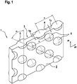
- the Fig. 1 shows a three-dimensional representation of a sipe 1 of the tread pattern 1 of Fig. 1 , Shown are the two sipe walls 2, 3, which include a void volume 4 between them. Both sipe walls 2, 3 have at opposite positions bulges 5, which increase the void volume of the sipe at the location of the bulge 5.
- the bulges 5 are hemispherical, so that two opposite bulges 5 form "hollow" spheres.
- each three lobes 5 in an axial row per sipe wall 2, 3 are arranged.
- the distance a of two in the axial direction aR adjacent lobes 5 is between 2 mm and 14 mm.
- the nearest adjacent lobes are spaced apart from one another in a direction other than the radial direction, which rows preferably enclose an angle ⁇ of 50 ° to 70 ° with the radial direction.
- the bulge 5 have a width b A of 0.6 mm to 2.4 mm, preferably in a tread tire of a car tire between 0.6 mm and 1.6 mm and preferably in a tread pattern of a truck tire between 1.0 mm and 2.4 mm, on, here 1.5 mm.
- the sipe 1 has outside the bulges a width b F of 0.3 mm to 1.2 mm, preferably in a tread tire profile of a car tire between 0.3 mm and 0.8 mm, more preferably of 0.5 mm and preferably at a tread pattern of a truck tire between 0.5 mm and 1.2 mm, here 0.8 mm.
- the Fig. 2 shows a three-dimensional representation of another sipe 1.
- the sipe 1 differs from the sipe of the Fig. 1 to the effect that - in the depth profile - the next adjacent bulges 5 are arranged in the radial direction rR.
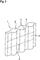
- the Fig. 3 shows a three-dimensional representation of yet another fine sipe 1.
- the sipe 1 differs from the sipe of the Fig. 2 in that - in the depth profile - the bulges 5 are arranged in the radial direction rR to each other such that they merge into each other and form radially extending channels 6, which preferably have a same cross section over their radial course.
Landscapes
- Engineering & Computer Science (AREA)
- Mechanical Engineering (AREA)
- Tires In General (AREA)
Description
- Die Erfindung betrifft ein Laufstreifenprofil eines Fahrzeugreifens mit Profilpositiven wie Profilblöcken oder Laufstreifenbändern, welche Feineinschnitte aufweisen, wobei die Breite eines Feineinschnittes durch zwei parallel zueinander angeordnete Feineinschnittwände begrenzt ist, welche ein Leervolumen zwischen sich einschließen und wobei die Feineinschnittwände Ausbuchtungen aufweisen, welche das Leervolumen des Feineinschnittes an der Stelle der Ausbuchtung erhöht und welche in axialer Richtung sowie in radialer Richtung verteilt an der Feineinschnittwand angeordnet sind, wobei beide Feineinschnittwände Ausbuchtungen aufweisen und wobei die Ausbuchtungen der einen Feineinschnittwand an gegengleichen Positionen zu den Ausbuchtungen der anderen Feineinschnittwand angeordnet sind.
- Ein derartiges Laufstreifenprofil ist aus der
JP 2005 329793 A - Feineinschnitte dienen beispielsweise bei Nutzfahrzeugreifen dazu, bei nasser Fahrbahn den Wasserfilm zu zertrennen, um bessere Nasseigenschaften dieses Laufstreifens zu erhalten.
- Bei PKW-Reifen sind die Feineinschnitte bei Fahrzeugreifen für den Einsatz unter winterlichen Fahrbedingungen ausgebildet und dienen beispielsweise dazu, die Fahreigenschafen auf winterlicher Fahrbahn zu verbessern, indem vermehrt Griffkanten zur Verfügung gestellt werden und indem der in den Feineinschnitten aufgenommene Schnee die Haftung des Reifens durch eine Schnee-Schnee-Verzahnung erhöht.
- Üblicherweise weisen Feineinschnitte eine Breite von 0,5 mm bis 3 mm auf.
- Aus der
US 2012/090749 A1 , derUS 2011/120610 A1 sowie derJP 2005 262973 A - Aus der
EP 1 073 562 B1 ist ein Laufstreifenprofil mit 3 D-Feineinschnitten bekannt, indem eine Feineinschnittwand Ausbuchtungen aufweist, welche über die Feineinschnittwand verteilt angeordnet sind. Die Ausbuchtungen erweitern das Leervolumen des Feineinschnittes an dieser Stelle. Jedoch weist die andere Feineinschnittwand gegengleiche Materialansammlungen auf, welche beim Betrieb des Laufstreifenprofils in die Ausbuchtungen eingreifen. Hierdurch ist eine Verschränkung der gegenüberliegenden Feineinschnittwände erreicht, wodurch die Profilblöcke bzw. -bänder versteift sind. - Man ist bestrebt, die Fahreigenschaften des Reifens, insbesondere die Wintereigenschaften weiter zu verbessern.
- Es ist die Aufgabe der Erfindung, ein Laufstreifenprofil eines Fahrzeugreifens zur Verfügung zu stellen, das sowohl verbesserte Wintereigenschaften als auch verbesserte Nass- und Trockenbremseigenschaften aufweist.
- Gelöst wird die Aufgabe, indem die Ausbuchtungen in axialen Reihen beabstandet voneinander angeordnet sind, wobei der Abstand in axialer Richtung zwischen 2 mm und 14 mm, vorzugsweise bei einem Laufstreifenprofil eines PKW-Reifens zwischen 1,5 mm und 4 mm und vorzugsweise bei einem Laufstreifenprofil eines LKW-Reifens zwischen 8 mm und 14 mm, beträgt und dass im Tiefenverlauf der Feineinschnittwand die am nächsten benachbarten Ausbuchtungen beabstandet voneinander in einer von der radialen Richtung abweichenden Richtung verlaufenden Reihe angeordnet sind, wobei diese Reihen vorzugsweise einen Winkel α von 50° bis 70° mit der radialen Richtung einschließen.
- Es ist erfindungsgemäß ein Laufstreifenprofil geschaffen, das durch die beidseitig an gegengleichen Position angeordneten Ausbuchtungen ein lokal vergrößertes Leervolumen aufweist, welches auch beim Schließen des Feineinschnittes verbleibt. Die Ausbuchtungen sind derart ausgeführt, dass diese an der Feineinschnittwand beginnend von dieser weg in das Profilelement hinein reicht. Durch diese Anordnungen ist die Anordnung von vielen Ausbuchtungen ermöglicht. Mehrere Ausbuchtungen insbesondere in axialer Richtung, verstärken die Wirkung der Ausbuchtungen, z.B. kann verstärkt durch Kapillareffekte Wasser aufgenommen werden.
- Im Durchlauf des Reifens auf der Fahrbahnoberfläche verformen sich die Profilelemente des Laufstreifens. Die Art und Intensität dieser Verformung wird u.a. durch die Geometrie der in diesem Profilelement angeordneten Feineinschnitte bestimmt. Bei dem erfindungsgemäßen Laufstreifen verbleibt während der Verformung immer eine durch die Ausbuchtungen geschaffene Öffnung und Hohlräume der Feineinschnitte. In dieser Öffnung / Hohlraum kann für gute Fahreigenschaften auf winterlicher Fahrbahn Schnee aufgenommen werden, wodurch eine vorteilhafte Schnee-Schnee-Reibung und somit eine vorteilhafte Haftung erreicht ist. Andererseits sind die Öffnungen auf nasser Fahrbahn vorteilhaft, weil Wasser in diesen Öffnungen aufgenommen werden kann. Zudem sind durch die verbleibenden Öffnungen mehr Kanten zur Verfügung gestellt, wodurch verbesserte Trocken- und Nassbremseigenschaften erhalten sind.
- "Axiale Richtung" meint die Richtung entlang der Reifenachse.
- "Umfangsrichtung" meint die Richtung entlang des Reifenabrollens.
- "Radiale Richtung" meint die Richtung vom Reifenmittelpunkt zum Laufstreifen.
- "Breite des Feineinschnittes" meint die Ausdehnung eines Feineinschnittes quer zu seiner Längserstreckung.
- "Abstand zweier Ausbuchtungen" meint die kürzeste Strecke in radialer oder axialer oder diagonaler Richtung vom Mittelpunkt der einen Ausbuchtung zum Mittelpunkt der anderen Ausbuchtung.
- In einer Ausführungsform sind die Ausbuchtungen im Wesentlichen halbkugelförmig oder zylinderförmig. In einer 3D-Betrachtung des Feineinschnittes bilden zwei gegenüberliegende Ausbuchtungen kugel- oder zylinderförmige Hohlräume, welche über die radial verlaufenden Feineinschnittwände hinaus in das Profilelement reichen. Die Hohlräume bleiben auch unter Last erhalten, sind vorteilhaft für die Wasseraufnahme und somit vorteilhaft für die Nasseigenschaften. Ebenfalls kann sich in den Hohlräumen Schnee fangen, wodurch die Schneetraktion vorteilhaft verbessert ist.
- In einer anderen Ausführungsform sind die Ausbuchtungen im Wesentlichen pyramidenförmig, wobei die Grundfläche der Pyramide in der Feineinschnittwand angeordnet ist und die Spitze der Pyramide von dem Feineinschnitt weg weisend ausgerichtet ist.
- Je nach Wahl der Geometrie der Ausbuchtungen können Vorteile bei der Entformbarkeit oder z.B. einer platzsparenden Anordnung der Ausbuchtungen haben.
- Vorteilhaft ist es, wenn die Ausbuchtung eine Breite von 0,6 mm bis 2,4 mm, vorzugsweise bei einem Laufstreifenprofil eines PKW-Reifens zwischen 0,6 mm und 1,6 mm und vorzugsweise bei einem Laufstreifenprofil eines LKW-Reifens zwischen 1,0 mm und 2,4 mm, aufweist.
- Vorteilhaft ist es, wenn der Feineinschnitt außerhalb der Ausbuchtungen eine Breite von 0,3 mm bis 1,2 mm, vorzugsweise bei einem Laufstreifenprofil eines PKW-Reifens zwischen 0,3 mm und 0,8 mm, besonders bevorzugt von 0,5 mm und vorzugsweise bei einem Laufstreifenprofil eines LKW-Reifens zwischen 0,5 mm und 1,2 mm aufweist.
- Ein derartiges Laufstreifenprofil ist in einem Fahrzeugreifen, vorzugsweise einem Nutzfahrzeugreifen oder einem PKW-Reifen einzusetzen.
- Weitere Merkmale, Vorteile und Einzelheiten der Erfindung werden anhand der Zeichnungen, die schematische Ausführungsbeispiele darstellen, näher beschrieben. Dabei zeigt die
- Fig. 1
- eine dreidimensionale Darstellung eines Feineinschnittes;
- Fig. 2
- eine dreidimensionale Darstellung eines anderen Feineinschnittes;
- Fig. 3
- eine dreidimensionale Darstellung eines wiederum anderen Feineinschnittes.
- Die
Fig. 1 zeigt eine dreidimensionale Darstellung eines Feineinschnittes 1 des Laufstreifenprofils 1 derFig. 1 . Dargestellt sind die beiden Feineinschnittwände 2, 3, welche zwischen sich ein Leervolumen 4 einschließen. Beide Feineinschnittwände 2, 3 weisen an gegengleichen Positionen Ausbuchtungen 5 auf, welche das Leervolumen des Feineinschnittes an der Stelle der Ausbuchtung 5 erhöhen. Hier sind die Ausbuchtungen 5 halbkugelförmig, so dass zwei gegengleiche Ausbuchtungen 5 "Hohl"-Kugeln ausbilden. - In axialer Richtung aR sind jeweils drei Ausbuchtungen 5 in einer axialen Reihe je Feineinschnittwand 2, 3 angeordnet. Der Abstand a zweier in axialer Richtung aR benachbarter Ausbuchtungen 5 beträgt zwischen 2 mm und 14 mm. Im Tiefenverlauf der Feineinschnittwand sind die am nächsten benachbarten Ausbuchtungen beabstandet voneinander in einer von der radialen Richtung abweichenden Richtung Reihe angeordnet sind, wobei diese Reihen vorzugsweise einen Winkel α von 50° bis 70° mit der radialen Richtung einschließen. Die Ausbuchtung 5 weisen eine Breite bA von 0,6 mm bis 2,4 mm, vorzugsweise bei einem Laufstreifenprofil eines PKW-Reifens zwischen 0,6 mm und 1,6 mm und vorzugsweise bei einem Laufstreifenprofil eines LKW-Reifens zwischen 1,0 mm und 2,4 mm, auf, hier 1,5 mm. Der Feineinschnitt 1 weist außerhalb der Ausbuchtungen eine Breite bF von 0,3 mm bis 1,2 mm, vorzugsweise bei einem Laufstreifenprofil eines PKW-Reifens zwischen 0,3 mm und 0,8 mm, besonders bevorzugt von 0,5 mm und vorzugsweise bei einem Laufstreifenprofil eines LKW-Reifens zwischen 0,5 mm und 1,2 mm auf, hier 0,8 mm.
- Die
Fig. 2 zeigt eine dreidimensionale Darstellung eines anderen Feineinschnittes 1. Der Feineinschnitt 1 unterscheidet sich von dem Feineinschnitt derFig. 1 dahingehend, dass - im Tiefenverlauf - die am nächsten benachbarten Ausbuchtungen 5 in radialer Richtung rR angeordnet sind. - Die
Fig. 3 zeigt eine dreidimensionale Darstellung eines wiederum anderen Feineinschnittes 1. Der Feineinschnitt 1 unterscheidet sich von dem Feineinschnitt derFig. 2 dahingehend, dass -im Tiefenverlauf - die Ausbuchtungen 5 in radialer Richtung rR derart zueinander angeordnet sind, dass diese ineinander übergehen und radial verlaufende Kanäle 6 bilden, welche vorzugsweise über ihren radialen Verlauf einen gleichen Querschnitt aufweisen. -
- 1
- Feineinschnitt
- 2
- Feineinschnittwand
- 3
- Feineinschnittwand
- 4
- Leervolumen
- 5
- Ausbuchtung
- 6
- Kanal
- a
- Abstand zweier Ausbuchtungen
- bA
- Breite Ausbuchtung
- bF
- Breite Feineinschnitt
- rR
- radiale Richtung
- aR
- axiale Richtung
- uR
- Umfangsrichtung
Claims (7)
- Laufstreifenprofil eines Fahrzeugreifens mit Profilpositiven wie Profilblöcken oder Laufstreifenbändern, welche Feineinschnitte (1) aufweisen, wobei die Breite eines Feineinschnittes (bF) durch zwei parallel zueinander angeordnete Feineinschnittwände (2, 3) begrenzt ist, welche ein Leervolumen (4) zwischen sich einschließen und wobei die Feineinschnittwände (2, 3) Ausbuchtungen (5) aufweisen, welche das Leervolumen (4) des Feineinschnittes an der Stelle der Ausbuchtung (5) erhöht und welche in axialer Richtung (aR) sowie in radialer Richtung (rR) verteilt an der Feineinschnittwand (2, 3) angeordnet sind, wobei beide Feineinschnittwände (2, 3) Ausbuchtungen (5) aufweisen und wobei die Ausbuchtungen (5) der einen Feineinschnittwand (2) an gegengleichen Positionen zu den Ausbuchtungen (5) der anderen Feineinschnittwand (3) angeordnet sind, dadurch gekennzeichnet, dass die Ausbuchtungen (5) in axialen Reihen beabstandet voneinander angeordnet sind, wobei der Abstand (a) in axialer Richtung zwischen 2 mm und 14 mm, vorzugsweise bei einem Laufstreifenprofil eines PKW-Reifens zwischen 1,5 mm und 4 mm und vorzugsweise bei einem Laufstreifenprofil eines LKW-Reifens zwischen 8 mm und 14 mm, beträgt und dass im Tiefenverlauf der Feineinschnittwand (2, 3) die am nächsten benachbarten Ausbuchtungen (5) beabstandet voneinander in einer von der radialen Richtung (rR) abweichenden Richtung verlaufenden Reihe angeordnet sind, wobei diese Reihen vorzugsweise einen Winkel α von 50° bis 70° mit der radialen Richtung (rR) einschließen.
- Laufstreifenprofil nach Anspruch 1,
dadurch gekennzeichnet, dass die Ausbuchtungen (5) im Wesentlichen halbkugelförmig oder zylinderförmig sind. - Laufstreifenprofil nach Anspruch 1, dadurch gekennzeichnet, dass die Ausbuchtungen (5) im Wesentlichen pyramidenförmig sind, wobei die Grundfläche der Pyramide in der Feineinschnittwand (2, 3) angeordnet ist und die Spitze der Pyramide von dem Feineinschnitt (1) wegweisend ausgerichtet ist.
- Laufstreifenprofil nach einem oder mehreren der vorangehenden Ansprüche, dadurch gekennzeichnet, dass die Ausbuchtung (5) eine Breite (bA) von 0,6 mm bis 2,4 mm, vorzugsweise bei einem Laufstreifenprofil eines PKW-Reifens zwischen 0,6 mm und 1,6 mm und vorzugsweise bei einem Laufstreifenprofil eines LKW-Reifens zwischen 1,0 mm und 2,4 mm, aufweist.
- Laufstreifenprofil nach einem oder mehreren der vorangehenden Ansprüche, dadurch gekennzeichnet, dass der Feineinschnitt (1) außerhalb der Ausbuchtungen eine Breite (bF) von 0,3 mm bis 1,2 mm, vorzugsweise bei einem Laufstreifenprofil eines PKW-Reifens zwischen 0,3 mm und 0,8 mm, besonders bevorzugt von 0,5 mm und vorzugsweise bei einem Laufstreifenprofil eines LKW-Reifens zwischen 0,5 mm und 1,2 mm aufweist.
- Fahrzeugluftreifen, dadurch gekennzeichnet, dass dieser ein Laufstreifenprofil gemäß eines oder mehrerer der vorangehenden Ansprüche aufweist.
- Fahrzeugluftreifen nach Anspruch 6, dadurch gekennzeichnet dass dieser ein Nutzfahrzeugreifen oder ein PKW-Reifen ist.
Priority Applications (1)
| Application Number | Priority Date | Filing Date | Title |
|---|---|---|---|
| PL13724235T PL2852500T3 (pl) | 2012-05-22 | 2013-05-17 | Profil bieżnika opony pojazdu |
Applications Claiming Priority (2)
| Application Number | Priority Date | Filing Date | Title |
|---|---|---|---|
| DE102012104403A DE102012104403A1 (de) | 2012-05-22 | 2012-05-22 | Laufstreifenprofil eines Fahrzeugluftreifens |
| PCT/EP2013/060223 WO2013174737A1 (de) | 2012-05-22 | 2013-05-17 | Laufstreifenprofil eines fahrzeugluftreifens |
Publications (2)
| Publication Number | Publication Date |
|---|---|
| EP2852500A1 EP2852500A1 (de) | 2015-04-01 |
| EP2852500B1 true EP2852500B1 (de) | 2018-07-11 |
Family
ID=48470957
Family Applications (1)
| Application Number | Title | Priority Date | Filing Date |
|---|---|---|---|
| EP13724235.0A Active EP2852500B1 (de) | 2012-05-22 | 2013-05-17 | Laufstreifenprofil eines fahrzeugluftreifens |
Country Status (6)
| Country | Link |
|---|---|
| EP (1) | EP2852500B1 (de) |
| CN (1) | CN104582981B (de) |
| DE (1) | DE102012104403A1 (de) |
| ES (1) | ES2684727T3 (de) |
| PL (1) | PL2852500T3 (de) |
| WO (1) | WO2013174737A1 (de) |
Families Citing this family (4)
| Publication number | Priority date | Publication date | Assignee | Title |
|---|---|---|---|---|
| EP2961620B1 (de) * | 2013-02-28 | 2019-08-14 | Pirelli Tyre S.p.A. | Winterreifen |
| DE102014203546A1 (de) * | 2014-02-27 | 2015-08-27 | Continental Reifen Deutschland Gmbh | Fahrzeugluftreifen |
| DE102014210823A1 (de) | 2014-06-06 | 2015-12-17 | Continental Reifen Deutschland Gmbh | Fahrzeugluftreifen |
| DE102017219532A1 (de) | 2017-11-03 | 2019-05-09 | Continental Reifen Deutschland Gmbh | Nutzfahrzeugreifen |
Family Cites Families (6)
| Publication number | Priority date | Publication date | Assignee | Title |
|---|---|---|---|---|
| WO1999048707A1 (en) | 1998-03-25 | 1999-09-30 | The Goodyear Tire & Rubber Company | Tire tread and mold for making treads |
| JP2005262973A (ja) * | 2004-03-17 | 2005-09-29 | Bridgestone Corp | 空気入りタイヤ、サイプ形成用ブレード及びそのサイプ形成用ブレードを備えたタイヤ形成用金型 |
| JP4831723B2 (ja) * | 2004-05-19 | 2011-12-07 | 東洋ゴム工業株式会社 | 空気入りタイヤ |
| FR2924981B1 (fr) * | 2007-12-17 | 2009-11-27 | Michelin Soc Tech | Bande de roulement pour pneumatique neige. |
| JP5099914B2 (ja) * | 2008-10-03 | 2012-12-19 | 東洋ゴム工業株式会社 | 空気入りタイヤ |
| CN102442166B (zh) * | 2010-10-13 | 2015-07-01 | 东洋橡胶工业株式会社 | 充气轮胎 |
-
2012
- 2012-05-22 DE DE102012104403A patent/DE102012104403A1/de not_active Withdrawn
-
2013
- 2013-05-17 EP EP13724235.0A patent/EP2852500B1/de active Active
- 2013-05-17 CN CN201380026795.7A patent/CN104582981B/zh active Active
- 2013-05-17 PL PL13724235T patent/PL2852500T3/pl unknown
- 2013-05-17 WO PCT/EP2013/060223 patent/WO2013174737A1/de not_active Ceased
- 2013-05-17 ES ES13724235.0T patent/ES2684727T3/es active Active
Non-Patent Citations (1)
| Title |
|---|
| None * |
Also Published As
| Publication number | Publication date |
|---|---|
| ES2684727T3 (es) | 2018-10-04 |
| CN104582981B (zh) | 2017-04-05 |
| DE102012104403A1 (de) | 2013-11-28 |
| EP2852500A1 (de) | 2015-04-01 |
| PL2852500T3 (pl) | 2018-11-30 |
| CN104582981A (zh) | 2015-04-29 |
| WO2013174737A1 (de) | 2013-11-28 |
Similar Documents
| Publication | Publication Date | Title |
|---|---|---|
| EP3110634B1 (de) | Fahrzeugluftreifen | |
| DE102006052740B4 (de) | Luftreifen | |
| EP2531361B1 (de) | Fahrzeugluftreifen | |
| DE102010060946A1 (de) | Fahrzeugluftreifen | |
| EP2159080B1 (de) | Fahrzeugluftreifen | |
| EP3383669B1 (de) | Fahrzeugluftreifen | |
| DE102012108383A1 (de) | Fahrzeugluftreifen | |
| EP2864137B1 (de) | Laufstreifenprofil eines fahrzeugreifens | |
| EP2852500B1 (de) | Laufstreifenprofil eines fahrzeugluftreifens | |
| EP2844503B1 (de) | Laufstreifenprofil eines fahrzeugreifens | |
| EP3034332B1 (de) | Fahrzeugluftreifen | |
| EP3441241B1 (de) | Fahrzeugluftreifen | |
| EP2660080B1 (de) | Laufstreifenprofil eines Fahrzeugreifens | |
| EP2376297B1 (de) | Fahrzeugluftreifen | |
| EP2943359B1 (de) | Fahrzeugluftreifen für den einsatz unter winterlichen fahrbedingungen | |
| EP3551477B1 (de) | Fahrzeugluftreifen | |
| EP2855172B1 (de) | Fahrzeugluftreifen | |
| EP3390108B1 (de) | Fahrzeugluftreifen | |
| EP2660081A1 (de) | Laufstreifenprofil eines Fahrzeugreifens | |
| DE102007026814A1 (de) | Fahrzeugluftreifen | |
| DE102010000484A1 (de) | Fahrzeugluftreifen | |
| EP4244079B1 (de) | Fahrzeugluftreifen | |
| DE102013225302A1 (de) | Fahrzeugluftreifen | |
| EP3415344B1 (de) | Fahrzeugluftreifen | |
| EP2055506A1 (de) | Laufflächenprofil eines Fahrzeugluftreifens mit Profilblockelementen |
Legal Events
| Date | Code | Title | Description |
|---|---|---|---|
| PUAI | Public reference made under article 153(3) epc to a published international application that has entered the european phase |
Free format text: ORIGINAL CODE: 0009012 |
|
| 17P | Request for examination filed |
Effective date: 20141222 |
|
| AK | Designated contracting states |
Kind code of ref document: A1 Designated state(s): AL AT BE BG CH CY CZ DE DK EE ES FI FR GB GR HR HU IE IS IT LI LT LU LV MC MK MT NL NO PL PT RO RS SE SI SK SM TR |
|
| AX | Request for extension of the european patent |
Extension state: BA ME |
|
| DAX | Request for extension of the european patent (deleted) | ||
| GRAP | Despatch of communication of intention to grant a patent |
Free format text: ORIGINAL CODE: EPIDOSNIGR1 |
|
| STAA | Information on the status of an ep patent application or granted ep patent |
Free format text: STATUS: GRANT OF PATENT IS INTENDED |
|
| INTG | Intention to grant announced |
Effective date: 20180306 |
|
| GRAS | Grant fee paid |
Free format text: ORIGINAL CODE: EPIDOSNIGR3 |
|
| GRAA | (expected) grant |
Free format text: ORIGINAL CODE: 0009210 |
|
| STAA | Information on the status of an ep patent application or granted ep patent |
Free format text: STATUS: THE PATENT HAS BEEN GRANTED |
|
| AK | Designated contracting states |
Kind code of ref document: B1 Designated state(s): AL AT BE BG CH CY CZ DE DK EE ES FI FR GB GR HR HU IE IS IT LI LT LU LV MC MK MT NL NO PL PT RO RS SE SI SK SM TR |
|
| REG | Reference to a national code |
Ref country code: GB Ref legal event code: FG4D Free format text: NOT ENGLISH |
|
| REG | Reference to a national code |
Ref country code: CH Ref legal event code: EP |
|
| REG | Reference to a national code |
Ref country code: AT Ref legal event code: REF Ref document number: 1016485 Country of ref document: AT Kind code of ref document: T Effective date: 20180715 |
|
| REG | Reference to a national code |
Ref country code: IE Ref legal event code: FG4D Free format text: LANGUAGE OF EP DOCUMENT: GERMAN |
|
| REG | Reference to a national code |
Ref country code: DE Ref legal event code: R096 Ref document number: 502013010591 Country of ref document: DE |
|
| REG | Reference to a national code |
Ref country code: ES Ref legal event code: FG2A Ref document number: 2684727 Country of ref document: ES Kind code of ref document: T3 Effective date: 20181004 |
|
| REG | Reference to a national code |
Ref country code: NL Ref legal event code: FP |
|
| REG | Reference to a national code |
Ref country code: LT Ref legal event code: MG4D Ref country code: NO Ref legal event code: T2 Effective date: 20180711 |
|
| PG25 | Lapsed in a contracting state [announced via postgrant information from national office to epo] |
Ref country code: FI Free format text: LAPSE BECAUSE OF FAILURE TO SUBMIT A TRANSLATION OF THE DESCRIPTION OR TO PAY THE FEE WITHIN THE PRESCRIBED TIME-LIMIT Effective date: 20180711 Ref country code: RS Free format text: LAPSE BECAUSE OF FAILURE TO SUBMIT A TRANSLATION OF THE DESCRIPTION OR TO PAY THE FEE WITHIN THE PRESCRIBED TIME-LIMIT Effective date: 20180711 Ref country code: IS Free format text: LAPSE BECAUSE OF FAILURE TO SUBMIT A TRANSLATION OF THE DESCRIPTION OR TO PAY THE FEE WITHIN THE PRESCRIBED TIME-LIMIT Effective date: 20181111 Ref country code: BG Free format text: LAPSE BECAUSE OF FAILURE TO SUBMIT A TRANSLATION OF THE DESCRIPTION OR TO PAY THE FEE WITHIN THE PRESCRIBED TIME-LIMIT Effective date: 20181011 Ref country code: SE Free format text: LAPSE BECAUSE OF FAILURE TO SUBMIT A TRANSLATION OF THE DESCRIPTION OR TO PAY THE FEE WITHIN THE PRESCRIBED TIME-LIMIT Effective date: 20180711 Ref country code: GR Free format text: LAPSE BECAUSE OF FAILURE TO SUBMIT A TRANSLATION OF THE DESCRIPTION OR TO PAY THE FEE WITHIN THE PRESCRIBED TIME-LIMIT Effective date: 20181012 Ref country code: LT Free format text: LAPSE BECAUSE OF FAILURE TO SUBMIT A TRANSLATION OF THE DESCRIPTION OR TO PAY THE FEE WITHIN THE PRESCRIBED TIME-LIMIT Effective date: 20180711 |
|
| PG25 | Lapsed in a contracting state [announced via postgrant information from national office to epo] |
Ref country code: AL Free format text: LAPSE BECAUSE OF FAILURE TO SUBMIT A TRANSLATION OF THE DESCRIPTION OR TO PAY THE FEE WITHIN THE PRESCRIBED TIME-LIMIT Effective date: 20180711 Ref country code: LV Free format text: LAPSE BECAUSE OF FAILURE TO SUBMIT A TRANSLATION OF THE DESCRIPTION OR TO PAY THE FEE WITHIN THE PRESCRIBED TIME-LIMIT Effective date: 20180711 Ref country code: HR Free format text: LAPSE BECAUSE OF FAILURE TO SUBMIT A TRANSLATION OF THE DESCRIPTION OR TO PAY THE FEE WITHIN THE PRESCRIBED TIME-LIMIT Effective date: 20180711 |
|
| REG | Reference to a national code |
Ref country code: DE Ref legal event code: R097 Ref document number: 502013010591 Country of ref document: DE |
|
| PG25 | Lapsed in a contracting state [announced via postgrant information from national office to epo] |
Ref country code: CZ Free format text: LAPSE BECAUSE OF FAILURE TO SUBMIT A TRANSLATION OF THE DESCRIPTION OR TO PAY THE FEE WITHIN THE PRESCRIBED TIME-LIMIT Effective date: 20180711 Ref country code: IT Free format text: LAPSE BECAUSE OF FAILURE TO SUBMIT A TRANSLATION OF THE DESCRIPTION OR TO PAY THE FEE WITHIN THE PRESCRIBED TIME-LIMIT Effective date: 20180711 Ref country code: RO Free format text: LAPSE BECAUSE OF FAILURE TO SUBMIT A TRANSLATION OF THE DESCRIPTION OR TO PAY THE FEE WITHIN THE PRESCRIBED TIME-LIMIT Effective date: 20180711 Ref country code: EE Free format text: LAPSE BECAUSE OF FAILURE TO SUBMIT A TRANSLATION OF THE DESCRIPTION OR TO PAY THE FEE WITHIN THE PRESCRIBED TIME-LIMIT Effective date: 20180711 |
|
| PLBE | No opposition filed within time limit |
Free format text: ORIGINAL CODE: 0009261 |
|
| STAA | Information on the status of an ep patent application or granted ep patent |
Free format text: STATUS: NO OPPOSITION FILED WITHIN TIME LIMIT |
|
| PG25 | Lapsed in a contracting state [announced via postgrant information from national office to epo] |
Ref country code: DK Free format text: LAPSE BECAUSE OF FAILURE TO SUBMIT A TRANSLATION OF THE DESCRIPTION OR TO PAY THE FEE WITHIN THE PRESCRIBED TIME-LIMIT Effective date: 20180711 Ref country code: SM Free format text: LAPSE BECAUSE OF FAILURE TO SUBMIT A TRANSLATION OF THE DESCRIPTION OR TO PAY THE FEE WITHIN THE PRESCRIBED TIME-LIMIT Effective date: 20180711 Ref country code: SK Free format text: LAPSE BECAUSE OF FAILURE TO SUBMIT A TRANSLATION OF THE DESCRIPTION OR TO PAY THE FEE WITHIN THE PRESCRIBED TIME-LIMIT Effective date: 20180711 |
|
| 26N | No opposition filed |
Effective date: 20190412 |
|
| PGFP | Annual fee paid to national office [announced via postgrant information from national office to epo] |
Ref country code: NL Payment date: 20190521 Year of fee payment: 7 |
|
| PGFP | Annual fee paid to national office [announced via postgrant information from national office to epo] |
Ref country code: PL Payment date: 20190404 Year of fee payment: 7 |
|
| PG25 | Lapsed in a contracting state [announced via postgrant information from national office to epo] |
Ref country code: SI Free format text: LAPSE BECAUSE OF FAILURE TO SUBMIT A TRANSLATION OF THE DESCRIPTION OR TO PAY THE FEE WITHIN THE PRESCRIBED TIME-LIMIT Effective date: 20180711 |
|
| REG | Reference to a national code |
Ref country code: CH Ref legal event code: PL |
|
| GBPC | Gb: european patent ceased through non-payment of renewal fee |
Effective date: 20190517 |
|
| PG25 | Lapsed in a contracting state [announced via postgrant information from national office to epo] |
Ref country code: MC Free format text: LAPSE BECAUSE OF FAILURE TO SUBMIT A TRANSLATION OF THE DESCRIPTION OR TO PAY THE FEE WITHIN THE PRESCRIBED TIME-LIMIT Effective date: 20180711 Ref country code: CH Free format text: LAPSE BECAUSE OF NON-PAYMENT OF DUE FEES Effective date: 20190531 Ref country code: LI Free format text: LAPSE BECAUSE OF NON-PAYMENT OF DUE FEES Effective date: 20190531 |
|
| REG | Reference to a national code |
Ref country code: BE Ref legal event code: MM Effective date: 20190531 |
|
| PG25 | Lapsed in a contracting state [announced via postgrant information from national office to epo] |
Ref country code: LU Free format text: LAPSE BECAUSE OF NON-PAYMENT OF DUE FEES Effective date: 20190517 |
|
| PG25 | Lapsed in a contracting state [announced via postgrant information from national office to epo] |
Ref country code: TR Free format text: LAPSE BECAUSE OF FAILURE TO SUBMIT A TRANSLATION OF THE DESCRIPTION OR TO PAY THE FEE WITHIN THE PRESCRIBED TIME-LIMIT Effective date: 20180711 |
|
| PG25 | Lapsed in a contracting state [announced via postgrant information from national office to epo] |
Ref country code: IE Free format text: LAPSE BECAUSE OF NON-PAYMENT OF DUE FEES Effective date: 20190517 Ref country code: GB Free format text: LAPSE BECAUSE OF NON-PAYMENT OF DUE FEES Effective date: 20190517 |
|
| PG25 | Lapsed in a contracting state [announced via postgrant information from national office to epo] |
Ref country code: BE Free format text: LAPSE BECAUSE OF NON-PAYMENT OF DUE FEES Effective date: 20190531 |
|
| PG25 | Lapsed in a contracting state [announced via postgrant information from national office to epo] |
Ref country code: FR Free format text: LAPSE BECAUSE OF NON-PAYMENT OF DUE FEES Effective date: 20190531 Ref country code: PT Free format text: LAPSE BECAUSE OF FAILURE TO SUBMIT A TRANSLATION OF THE DESCRIPTION OR TO PAY THE FEE WITHIN THE PRESCRIBED TIME-LIMIT Effective date: 20181111 |
|
| REG | Reference to a national code |
Ref country code: AT Ref legal event code: MM01 Ref document number: 1016485 Country of ref document: AT Kind code of ref document: T Effective date: 20190517 |
|
| REG | Reference to a national code |
Ref country code: ES Ref legal event code: FD2A Effective date: 20200930 |
|
| PG25 | Lapsed in a contracting state [announced via postgrant information from national office to epo] |
Ref country code: ES Free format text: LAPSE BECAUSE OF NON-PAYMENT OF DUE FEES Effective date: 20190518 |
|
| PG25 | Lapsed in a contracting state [announced via postgrant information from national office to epo] |
Ref country code: AT Free format text: LAPSE BECAUSE OF NON-PAYMENT OF DUE FEES Effective date: 20190517 |
|
| REG | Reference to a national code |
Ref country code: NL Ref legal event code: MM Effective date: 20200601 |
|
| PG25 | Lapsed in a contracting state [announced via postgrant information from national office to epo] |
Ref country code: NL Free format text: LAPSE BECAUSE OF NON-PAYMENT OF DUE FEES Effective date: 20200601 |
|
| PG25 | Lapsed in a contracting state [announced via postgrant information from national office to epo] |
Ref country code: CY Free format text: LAPSE BECAUSE OF FAILURE TO SUBMIT A TRANSLATION OF THE DESCRIPTION OR TO PAY THE FEE WITHIN THE PRESCRIBED TIME-LIMIT Effective date: 20180711 |
|
| PG25 | Lapsed in a contracting state [announced via postgrant information from national office to epo] |
Ref country code: MT Free format text: LAPSE BECAUSE OF FAILURE TO SUBMIT A TRANSLATION OF THE DESCRIPTION OR TO PAY THE FEE WITHIN THE PRESCRIBED TIME-LIMIT Effective date: 20180711 Ref country code: HU Free format text: LAPSE BECAUSE OF FAILURE TO SUBMIT A TRANSLATION OF THE DESCRIPTION OR TO PAY THE FEE WITHIN THE PRESCRIBED TIME-LIMIT; INVALID AB INITIO Effective date: 20130517 |
|
| PG25 | Lapsed in a contracting state [announced via postgrant information from national office to epo] |
Ref country code: MK Free format text: LAPSE BECAUSE OF FAILURE TO SUBMIT A TRANSLATION OF THE DESCRIPTION OR TO PAY THE FEE WITHIN THE PRESCRIBED TIME-LIMIT Effective date: 20180711 |
|
| PGFP | Annual fee paid to national office [announced via postgrant information from national office to epo] |
Ref country code: NO Payment date: 20220523 Year of fee payment: 10 |
|
| PG25 | Lapsed in a contracting state [announced via postgrant information from national office to epo] |
Ref country code: PL Free format text: LAPSE BECAUSE OF NON-PAYMENT OF DUE FEES Effective date: 20200517 |
|
| REG | Reference to a national code |
Ref country code: NO Ref legal event code: MMEP |
|
| PG25 | Lapsed in a contracting state [announced via postgrant information from national office to epo] |
Ref country code: NO Free format text: LAPSE BECAUSE OF NON-PAYMENT OF DUE FEES Effective date: 20230531 |
|
| REG | Reference to a national code |
Ref country code: DE Ref legal event code: R081 Ref document number: 502013010591 Country of ref document: DE Owner name: CONTINENTAL REIFEN DEUTSCHLAND GMBH, DE Free format text: FORMER OWNER: CONTINENTAL REIFEN DEUTSCHLAND GMBH, 30165 HANNOVER, DE |
|
| PGFP | Annual fee paid to national office [announced via postgrant information from national office to epo] |
Ref country code: DE Payment date: 20250531 Year of fee payment: 13 |