EP3308942B1 - Stretch blowing machine - Google Patents
Stretch blowing machine Download PDFInfo
- Publication number
- EP3308942B1 EP3308942B1 EP17201245.2A EP17201245A EP3308942B1 EP 3308942 B1 EP3308942 B1 EP 3308942B1 EP 17201245 A EP17201245 A EP 17201245A EP 3308942 B1 EP3308942 B1 EP 3308942B1
- Authority
- EP
- European Patent Office
- Prior art keywords
- blow molding
- stretch
- molding machine
- machine according
- stretching rod
- Prior art date
- Legal status (The legal status is an assumption and is not a legal conclusion. Google has not performed a legal analysis and makes no representation as to the accuracy of the status listed.)
- Active
Links
- 238000007664 blowing Methods 0.000 title description 20
- 238000000071 blow moulding Methods 0.000 claims description 60
- 238000004519 manufacturing process Methods 0.000 claims description 13
- 230000008878 coupling Effects 0.000 claims description 8
- 238000010168 coupling process Methods 0.000 claims description 8
- 238000005859 coupling reaction Methods 0.000 claims description 8
- 238000004146 energy storage Methods 0.000 claims description 6
- 239000003990 capacitor Substances 0.000 claims description 3
- 238000009434 installation Methods 0.000 claims description 3
- 230000007246 mechanism Effects 0.000 claims description 2
- 230000000149 penetrating effect Effects 0.000 claims 1
- 238000000034 method Methods 0.000 description 13
- 230000008569 process Effects 0.000 description 12
- 230000001276 controlling effect Effects 0.000 description 4
- 230000008859 change Effects 0.000 description 3
- 238000004891 communication Methods 0.000 description 3
- 238000001816 cooling Methods 0.000 description 3
- 230000001105 regulatory effect Effects 0.000 description 3
- 230000003584 silencer Effects 0.000 description 2
- 238000000418 atomic force spectrum Methods 0.000 description 1
- 230000008901 benefit Effects 0.000 description 1
- 230000005540 biological transmission Effects 0.000 description 1
- 239000000969 carrier Substances 0.000 description 1
- 238000006243 chemical reaction Methods 0.000 description 1
- 238000004590 computer program Methods 0.000 description 1
- 238000006073 displacement reaction Methods 0.000 description 1
- 238000005516 engineering process Methods 0.000 description 1
- 230000002349 favourable effect Effects 0.000 description 1
- 239000007788 liquid Substances 0.000 description 1
- 239000000314 lubricant Substances 0.000 description 1
- 238000005461 lubrication Methods 0.000 description 1
- 230000003071 parasitic effect Effects 0.000 description 1
- 230000002093 peripheral effect Effects 0.000 description 1
- 238000003825 pressing Methods 0.000 description 1
- 238000003860 storage Methods 0.000 description 1
- 230000036962 time dependent Effects 0.000 description 1
Images

Classifications
-
- B—PERFORMING OPERATIONS; TRANSPORTING
- B29—WORKING OF PLASTICS; WORKING OF SUBSTANCES IN A PLASTIC STATE IN GENERAL
- B29C—SHAPING OR JOINING OF PLASTICS; SHAPING OF MATERIAL IN A PLASTIC STATE, NOT OTHERWISE PROVIDED FOR; AFTER-TREATMENT OF THE SHAPED PRODUCTS, e.g. REPAIRING
- B29C49/00—Blow-moulding, i.e. blowing a preform or parison to a desired shape within a mould; Apparatus therefor
- B29C49/08—Biaxial stretching during blow-moulding
- B29C49/10—Biaxial stretching during blow-moulding using mechanical means for prestretching
- B29C49/12—Stretching rods
-
- B—PERFORMING OPERATIONS; TRANSPORTING
- B29—WORKING OF PLASTICS; WORKING OF SUBSTANCES IN A PLASTIC STATE IN GENERAL
- B29C—SHAPING OR JOINING OF PLASTICS; SHAPING OF MATERIAL IN A PLASTIC STATE, NOT OTHERWISE PROVIDED FOR; AFTER-TREATMENT OF THE SHAPED PRODUCTS, e.g. REPAIRING
- B29C49/00—Blow-moulding, i.e. blowing a preform or parison to a desired shape within a mould; Apparatus therefor
- B29C49/42—Component parts, details or accessories; Auxiliary operations
- B29C49/78—Measuring, controlling or regulating
- B29C49/783—Measuring, controlling or regulating blowing pressure
- B29C2049/7834—Pressure increase speed, e.g. dependent on stretch or position
-
- B—PERFORMING OPERATIONS; TRANSPORTING
- B29—WORKING OF PLASTICS; WORKING OF SUBSTANCES IN A PLASTIC STATE IN GENERAL
- B29C—SHAPING OR JOINING OF PLASTICS; SHAPING OF MATERIAL IN A PLASTIC STATE, NOT OTHERWISE PROVIDED FOR; AFTER-TREATMENT OF THE SHAPED PRODUCTS, e.g. REPAIRING
- B29C49/00—Blow-moulding, i.e. blowing a preform or parison to a desired shape within a mould; Apparatus therefor
- B29C49/42—Component parts, details or accessories; Auxiliary operations
- B29C49/78—Measuring, controlling or regulating
- B29C2049/7879—Stretching, e.g. stretch rod
-
- B—PERFORMING OPERATIONS; TRANSPORTING
- B29—WORKING OF PLASTICS; WORKING OF SUBSTANCES IN A PLASTIC STATE IN GENERAL
- B29C—SHAPING OR JOINING OF PLASTICS; SHAPING OF MATERIAL IN A PLASTIC STATE, NOT OTHERWISE PROVIDED FOR; AFTER-TREATMENT OF THE SHAPED PRODUCTS, e.g. REPAIRING
- B29C2949/00—Indexing scheme relating to blow-moulding
- B29C2949/07—Preforms or parisons characterised by their configuration
- B29C2949/0715—Preforms or parisons characterised by their configuration the preform having one end closed
-
- B—PERFORMING OPERATIONS; TRANSPORTING
- B29—WORKING OF PLASTICS; WORKING OF SUBSTANCES IN A PLASTIC STATE IN GENERAL
- B29C—SHAPING OR JOINING OF PLASTICS; SHAPING OF MATERIAL IN A PLASTIC STATE, NOT OTHERWISE PROVIDED FOR; AFTER-TREATMENT OF THE SHAPED PRODUCTS, e.g. REPAIRING
- B29C49/00—Blow-moulding, i.e. blowing a preform or parison to a desired shape within a mould; Apparatus therefor
- B29C49/02—Combined blow-moulding and manufacture of the preform or the parison
- B29C49/06—Injection blow-moulding
-
- B—PERFORMING OPERATIONS; TRANSPORTING
- B29—WORKING OF PLASTICS; WORKING OF SUBSTANCES IN A PLASTIC STATE IN GENERAL
- B29C—SHAPING OR JOINING OF PLASTICS; SHAPING OF MATERIAL IN A PLASTIC STATE, NOT OTHERWISE PROVIDED FOR; AFTER-TREATMENT OF THE SHAPED PRODUCTS, e.g. REPAIRING
- B29C49/00—Blow-moulding, i.e. blowing a preform or parison to a desired shape within a mould; Apparatus therefor
- B29C49/08—Biaxial stretching during blow-moulding
- B29C49/10—Biaxial stretching during blow-moulding using mechanical means for prestretching
- B29C49/12—Stretching rods
- B29C49/1202—Means for fixing the stretching rod to the driving means, e.g. clamping means or bayonet connections
-
- B—PERFORMING OPERATIONS; TRANSPORTING
- B29—WORKING OF PLASTICS; WORKING OF SUBSTANCES IN A PLASTIC STATE IN GENERAL
- B29C—SHAPING OR JOINING OF PLASTICS; SHAPING OF MATERIAL IN A PLASTIC STATE, NOT OTHERWISE PROVIDED FOR; AFTER-TREATMENT OF THE SHAPED PRODUCTS, e.g. REPAIRING
- B29C49/00—Blow-moulding, i.e. blowing a preform or parison to a desired shape within a mould; Apparatus therefor
- B29C49/08—Biaxial stretching during blow-moulding
- B29C49/10—Biaxial stretching during blow-moulding using mechanical means for prestretching
- B29C49/122—Drive means therefor
- B29C49/1222—Pneumatic
-
- B—PERFORMING OPERATIONS; TRANSPORTING
- B29—WORKING OF PLASTICS; WORKING OF SUBSTANCES IN A PLASTIC STATE IN GENERAL
- B29C—SHAPING OR JOINING OF PLASTICS; SHAPING OF MATERIAL IN A PLASTIC STATE, NOT OTHERWISE PROVIDED FOR; AFTER-TREATMENT OF THE SHAPED PRODUCTS, e.g. REPAIRING
- B29C49/00—Blow-moulding, i.e. blowing a preform or parison to a desired shape within a mould; Apparatus therefor
- B29C49/08—Biaxial stretching during blow-moulding
- B29C49/10—Biaxial stretching during blow-moulding using mechanical means for prestretching
- B29C49/122—Drive means therefor
- B29C49/1229—Drive means therefor being a cam mechanism
-
- B—PERFORMING OPERATIONS; TRANSPORTING
- B29—WORKING OF PLASTICS; WORKING OF SUBSTANCES IN A PLASTIC STATE IN GENERAL
- B29C—SHAPING OR JOINING OF PLASTICS; SHAPING OF MATERIAL IN A PLASTIC STATE, NOT OTHERWISE PROVIDED FOR; AFTER-TREATMENT OF THE SHAPED PRODUCTS, e.g. REPAIRING
- B29C49/00—Blow-moulding, i.e. blowing a preform or parison to a desired shape within a mould; Apparatus therefor
- B29C49/08—Biaxial stretching during blow-moulding
- B29C49/10—Biaxial stretching during blow-moulding using mechanical means for prestretching
- B29C49/122—Drive means therefor
- B29C49/123—Electric drives, e.g. linear motors
-
- B—PERFORMING OPERATIONS; TRANSPORTING
- B29—WORKING OF PLASTICS; WORKING OF SUBSTANCES IN A PLASTIC STATE IN GENERAL
- B29C—SHAPING OR JOINING OF PLASTICS; SHAPING OF MATERIAL IN A PLASTIC STATE, NOT OTHERWISE PROVIDED FOR; AFTER-TREATMENT OF THE SHAPED PRODUCTS, e.g. REPAIRING
- B29C49/00—Blow-moulding, i.e. blowing a preform or parison to a desired shape within a mould; Apparatus therefor
- B29C49/28—Blow-moulding apparatus
- B29C49/30—Blow-moulding apparatus having movable moulds or mould parts
- B29C49/32—Blow-moulding apparatus having movable moulds or mould parts moving "to and fro"
-
- B—PERFORMING OPERATIONS; TRANSPORTING
- B29—WORKING OF PLASTICS; WORKING OF SUBSTANCES IN A PLASTIC STATE IN GENERAL
- B29C—SHAPING OR JOINING OF PLASTICS; SHAPING OF MATERIAL IN A PLASTIC STATE, NOT OTHERWISE PROVIDED FOR; AFTER-TREATMENT OF THE SHAPED PRODUCTS, e.g. REPAIRING
- B29C49/00—Blow-moulding, i.e. blowing a preform or parison to a desired shape within a mould; Apparatus therefor
- B29C49/42—Component parts, details or accessories; Auxiliary operations
- B29C49/42378—Handling malfunction
- B29C49/4238—Ejecting defective preforms or products
Definitions
- the invention relates to a stretch blow molding machine according to the preamble of patent claim 1.
- each blow molding station is assigned an electronic control unit in the rotating part, which controls both the stretch rod movement and the blow molding pressure and valve control in order to be able to quickly adjust the control for the production process when changing products.
- the control units in the rotating part are linked to one another via a bus system and connected to a higher-level control device outside the rotating part.
- Each blowing station can have a timer to control independently of the angle.
- the positions that the stretch rod passes through in the production process can be stored in recipes for different container types.
- the stretching speed can be freely parameterized independently of the production speed.
- Each control unit can have a servo frequency converter and not only controls the electrical stretching, but ideally all the functions of the blow molding station.
- a work cycle is initiated by a start signal and then runs off in a time-controlled manner.
- a computer program is processed in each control unit, so to speak.
- a time-dependent stretching process can be stored in the control unit.
- the electric servomotor for the stretch rod control is a rotating frequency converter motor, whereby the frequency conversion can also take over the control of the valves.
- the electric servomotor drives a stretching carriage carrying the stretching rod over a belt.
- the rotating part is supplied with operating media via at least one rotary feedthrough between the rotating and the stationary part.
- stretch blow molding machines are known in practice in which the movement of the stretch rods in each blow molding station is controlled by a cam control combined with at least one pneumatic cylinder. It is also known from practice to combine the electric servo motor with a pneumatic cylinder in electric stretching.
- a stretch blow molding machine whose blow molding stations are arranged in a stationary manner.
- the stretch rod drive system works with an electric servomotor, which drives the stretch carriage carrying the stretch rod via a toothed belt and causes the movement of the stretch rod to be path-controlled or force-controlled over time.
- Each blow molding station which may include several blow molds, is assigned an electronic control unit that controls the movement of the stretching rods and the application of blowing pressure in closed control circuits.
- suitable curves can be selected and processed from different stored curves of the stretch rod travel over time, the stretch rod force over time or the blowing nozzle pressure over time. With the path-controlled movement of the stretching rod, a maximum of one speed change is made.
- the first and second calibrations of the stretch rod control to be carried out later in the production process are slowly carried out, the results of which are stored.
- the stroke of the stretching rod is determined up to a distance from the bottom of the mold cavity that corresponds to the thickness of the bottle bottom, ie, if necessary, including a post-pressing path for the preform bottom.
- the stroke of the stretch rod to the preform base of the cold preform is determined minus a stroke increment for, for example, temperature-related deformations of hot preforms.
- the control circuits Based on the calibrations, the control circuits generate, for example, time-related lifting curves for the actual production process. Similarly, time-related pressure curves can be generated for a pre-blowing and a final blowing phase.
- the invention is based on the object of specifying a stretch blow molding machine of the type mentioned at the outset, which has inexpensive and universally applicable equipment, uncontrolled tightening forces being avoided during electrical stretching.
- the electronic control unit of the blow molding station can be universally used in various blow molding machines, which differ, for example, in the different stretch rod drive systems.
- This cost-effective and universally usable control unit can at least partially compensate for the additional costs of equipment for electrical stretching (shared-parts philosophy with regard to the control unit).
- the servo motor designed as a linear motor has a tubular design with respect to its rotor, forming a direct drive for the stretch rod which is coaxial or at least substantially coaxial with the stretch rod.
- a flat linear motor could also be used (is not part of the present invention)
- a tubular linear motor offers the advantage of avoiding uncontrolled attraction forces.
- a coaxial arrangement of the direct drive avoids moments on the linear guide, for example of the stretching carriage.
- the runner of the linear motor is offset to the side by a maximum of approximately 100 mm in relation to the stretch rod.
- this slight displacement requires only moderate moments in the linear guide of the stretching carriage and between the runner and the horizontal bar, however, is advantageous with regard to a quick and problem-free change of the horizontal bar.
- a linear motor in particular of a tubular design
- the electronic control unit offers the possibility of controlling the path, the force and the pressure or only the force and the path of the stretch rod. It is expedient to carry out path control until shortly before the end of the stretching process, and then at the end of the stretching process purely force control, e.g. in order to exactly define the overpressing of the container bottom.
- a generator operation of the electric servo motor in particular in the form of a linear motor, especially in a tubular design, allows electrical energy to be recovered, for example from the mass inertia or weight of the stretch rod drive system and/or from the lifting force on the stretch rod resulting from the pressure in the blow mold . Even if the amount of electrical energy recovered is small in comparison to the primary energy use, there is still a significant overall energy saving with often many blow molding stations and high production frequency.
- the control unit is expediently additionally equipped with hardware and software technology which can also be used in the blow molding station to control the blow molding nozzle and/or the valve section, expediently in association with the movement of the stretch rod or in association of the movement of the stretch rod with the control of the blow molding nozzle or valve section. This significantly reduces the control effort.
- control unit is installed separately from the electric servomotor in order to avoid mutual coupling of heat.
- At least one frequency converter of the electric servomotor (of the linear motor) is expediently separated from the servomotor, preferably with a distance that excludes heat coupling from the servomotor to the frequency converter or vice versa.
- the frequency converter can even be installed at a central installation point containing several or all frequency converters for the blow molding stations of the stretch blow molding machine.
- the frequency converters are housed centrally in a preferably cooled control cabinet.
- the control cabinet can be externally cooled, for example via a liquid cooling system, or with at least one so-called cold plate, which dissipates heat generated by the frequency converters, for example. This results in long, trouble-free service lives for the electrical and electronic equipment.
- electrical servomotors for electrical stretching are usually supplied with the supply voltage via frequency converters with intermediate circuits.
- the intermediate circuit voltage is conventionally generated by bridge rectifiers, which generate an intermediate circuit voltage that is approximately 1.4 times the input voltage. For example, with the usual mains voltage of 400 volts, an intermediate circuit voltage of approximately 560 volts is achieved.
- a disadvantage of this known system is that different mains voltages in different countries, e.g. in the USA, result in different intermediate circuit voltages for the electric servomotors, which under certain circumstances can even result in country-specific motor designs. This disadvantage is associated with significant power losses and inappropriately large cable cross-sections, and torque drops or losses in thrust or traction can occur.
- the respective frequency converter has at least one regulated step-up switching power supply, preferably in an intermediate circuit, with which the intermediate circuit voltage for supplying the respective electric servomotor can be increased to between approximately 600 and 900 volts, preferably between approximately 750 and 800 volts, raised and held.
- the intermediate circuit voltage can be maintained independently of the mains voltage or nominal voltage by means of the control and the step-up. Regardless of the country, the same servomotor types can always be used that are adapted to this increased intermediate circuit voltage. This allows the nominal current to be reduced, which results in lower power losses and conveniently small cable cross-sections.
- Such adapted electric servomotors can be operated at higher speeds, for example, and power or torque drops are reliably ruled out. Raising the intermediate circuit voltage is particularly useful in the case of linear motors as servomotors, for example for controlling the movement of the stretching rod.
- intermediate circuits from frequency converters in the rotating part are electrically coupled to intermediate circuits from frequency converters in the stationary part, and at least one energy store can be provided, preferably in the stationary part, to supply at least the servomotors in the rotating part in the event of a power failure.
- the energy storage provided in the stationary part allows one energy storage to be saved in the rotating part, e.g. to be able to carry out a controlled reset of all components in the event of a power failure and to be able to continue production immediately after the power failure has been rectified.
- At least one energy store preferably a flywheel, a capacitor bank or a battery or the like, is placed in the rotating part so that a reset to the required starting position can still be achieved in the event of a power failure (controlled shutdown of the system) so that no damage occurs when production starts again.
- the disadvantage of self-sufficiently operated and controlled electric servomotors, for example for controlling the movement of the stretching rod, is thus eliminated in a simple manner in terms of control technology.
- drive axles of the stationary part are electrically coupled to drive axles, preferably electric drives, in the rotating part.
- This coupling saves, for example, an encoder in the rotating part.
- the runner is guided relative to the stator by guide rings in the stator or at both ends of the stator or by at least one guide sleeve that is continuously or partially continuously integrated into the stator, or even by at least one guide that is arranged outside the stator .
- the external guide can have, for example, two spaced-apart guide members on a linear guide. This targeted guidance of the runner helps to generate high forces to a precise extent and to reduce wear between the runner and the stator, or to minimize parasitic friction losses.
- a force accumulator such as a spring or a pneumatic cylinder
- a force accumulator can be provided to at least partially compensate for restoring forces acting on the stretch rod from the blowing pressure in the blow mold, which assists the linear motor or keeps force peaks away from it.
- the energy accumulator can, preferably, even be actively controlled, depending on the respective process phase and/or stretch rod position.
- the energy storage allows the servo motor to be dimensioned smaller and equalizes return stroke forces on the stretch rod due to the pressure in the container in the blow mold.
- the linear motor in tubular design and the control unit of the blow molding station are expediently mounted on a bearing block that preferably also supports the valve section. At least the linear motor can be mounted there via a heat sink that dissipates heat generated during operation.
- the linear motor can have cooling ribs or air baffles for cooling, for example by targeted air flows.
- the bearing block has a linear guide for the stretching carriage, on which the stretching rod, which passes through a blowing carriage that is linearly adjustable relative to the stretching rod, is coupled to the runner, preferably in a separable manner.
- the bearing block with the components mounted on it can be prefabricated and its function can be checked before final assembly.
- a preferably adjustable and/or spring-loaded stop for the stretching carriage is arranged on the bearing block, which, for example, defines the end position of the stretching carriage after the return stroke and/or can be used for referencing or calibrating.
- the stretch blow molding machine 1 shows schematically a stretch blow molding machine 1 for stretch blow molding containers from preforms.
- the stretch blow molding machine 1 is of the rotary type with a blow wheel 2 carrying blow stations 4 on the peripheral side, which represents a part 1a rotating in relation to a stationary part 1b.
- the concept according to the invention can also be used without restriction for stretch blow molding machines in which the blow molding stations are arranged in a stationary manner (not shown).
- an electronic control unit 20 is arranged on the blow wheel 2 in each case.
- the control units 20 are supplied with energy, e.g. via connecting lines 11 and a rotary feedthrough 6, e.g optionally with several valves for controlling the blowing air supply during the blowing process.
- at least one sensor 22 can be provided at each blow molding station 4, which can be in communication with the respective control unit 20 as a transmitter.
- a timer 24 is optionally provided as further electronic equipment, which can initiate a working cycle, for example, as a function of a start signal.
- at least one sensor 30 can be provided as a position transmitter for detecting an angular position of the blow wheel 2 .
- a central control device 40 can be arranged in the standing part 1b be connected via a communication link 32 to the sensor 30, for example. Furthermore, a communication connection 13 can be provided, for example for the transmission of a start signal to the respective control unit 20 .
- a storage and/or input and/or display section 18 can be provided in at least one control unit 20 in order to store and read out data and the like.
- Each control unit 20 communicates via a connection 21 with the blow molding station 4 or at least the stretch rod drive system A or the servomotor 16 used for electric stretching.
- the electric servomotor 16 could (not shown) be combined with an energy store or a pneumatic cylinder, which assists or intervenes in the stretching process and is optionally also controlled by the control unit 20 .
- control unit 20 can be designed in such a way that it also controls the application of pressure during the blow molding process and/or the necessary adjustments of a blow nozzle and other components.
- a central lubrication device Z is also indicated schematically on the blow wheel 2, which supplies mechanical components on the blow wheel, e.g. metered, with lubricant.
- the movement of a blowing carriage can be controlled by a cam control, not shown (is not part of the present invention).
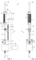
- the Figures 2 and 3 show a blow molding station 4 with the stretch rod drive system A for electrical stretching, the servomotor 16 here being a linear motor L, specifically a linear motor L of tubular design. Alternatively (is not part of the present invention), a linear motor of a different design, for example a flat design, could also be used.
- the linear motor L forms with its runner 34 a direct drive of a stretch rod 15.
- the linear motor L is installed separately from the control unit 20 with this on the head end of the bearing block 3, preferably with the interposition of the heat sink 5 at least for the linear motor L.
- the runner 34 is guided linearly in guide sleeves 33 at both ends of the linear motor and coaxially with the stretching rod 15, the runner 34 and the stretching rod 15 being in the region of a stretching carriage 14 via a separable coupling 17, e.g. B. for a stretch rod change, are coupled together.
- the stretching carriage 14 is guided on a linear guide 28 which is mounted on the side of the bearing block 3 facing the stretching rod 15 .
- the stretch rod 15 passes through a blowing carriage 9, which can be equipped with a lifting member 10 to raise the blowing carriage 9, for example to vent the finished container in the blow mold, not shown, if an outlet valve to a silencer 25 on a valve section 12 does not function properly should, and also a blowing nozzle 8 and the valve section 12.
- the valve section 12 is mounted on the bearing block 3 in this embodiment, as is a silencer 25, which is associated with an outlet valve of the valve section 12, not shown.
- a stop 7 for the stretching carriage 14 coupled to the stretching rod 15 can be provided on the bearing block 3, the stop 7 preferably being adjustable and/or cushioned.
- the stretching rod 15 is fixed in the stretching carriage 14 via the detachable coupling 17 and extends parallel to the bearing block 3 downwards to a blow mold, at the position of which a preform P is shown, from which a container with the mold is produced by superimposing a stretching process and a blowing process of the mold cavity of the blow mold is produced during the production process of the stretch blow molding machine 1.
- the stretching rod 15 passes through the blowing carriage 9, with which a blowing piston or the blowing nozzle 8 is connected, which can be raised relative to the blow mold and lowered to the mouth of the preform P until it is sealed.
- the blow mold comprises (not shown), for example, two mold halves and a mold base, at least the mold halves being arranged in carriers which can be moved via a mechanism, not shown, to open and close the blow mold and to lock it in the closed state.
- the blowing nozzle 8 is placed on the preform opening P in the production process before the pressure is applied via the valve section 12, for example in order to carry out a pre-blow phase with a lower pressure level and then a final blow-molding phase with a high pressure level, superimposed with the stretching process by the stretch rod 15 , which is pushed into the blow mold.
- the stop 7 can be used, for example, to calibrate the stretch rod drive system A Figures 2 and 3 an energy accumulator 35 indicated, for example a spring or a pneumatic cylinder, which is in drive connection with the runner 34 and assists the linear motor L and/or generates certain force curves or absorbs or compensates for forces which, for example, are caused by the pressure in the manufactured container when the container has not yet been vented, e.g . B. split blow mold the stretch rod 15 act in the return stroke direction.
- an energy accumulator 35 indicated, for example a spring or a pneumatic cylinder, which is in drive connection with the runner 34 and assists the linear motor L and/or generates certain force curves or absorbs or compensates for forces which, for example, are caused by the pressure in the manufactured container when the container has not yet been vented, e.g . B. split blow mold the stretch rod 15 act in the return stroke direction.
- the stretch rod 15 can perform its return stroke using this pressure in the blow mold, for example until it is intercepted by the blow carriage 9, or by the stop 7 on the bearing block, or by a counterforce of the force accumulator 35 or the linear motor L.
- the linear motor L can be switched off during the return stroke or run in generator mode and recover energy.
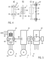
- the tubular design of the linear motor L as the servo motor 16 in the Figures 2 and 3 is schematic based on 4 shown, showing the three variants a), b) and c).
- in 4 are, similar to in 2 , Arranged at both ends of a stator 38 guide sleeves 33, which lead the rotor 34 centrally in the stator 38. These guide sleeves 33 could (indicated by dashed lines) also be integrated into the inside of the stator 38 .
- a continuous guide sleeve 33' is integrated into the stator 38, which here extends over the entire length of the stator 38 and has a smaller outer diameter than the stator 38.
- the stator 38 is otherwise designed with a largely circular cross-section.
- the guide sleeve 33' could only extend over part of the length of the stator 38 or be divided into, for example, two shorter guide sleeves.
- a guide 33" that is on the outside of the stator 38 is provided for the runner 34.
- the runner 34 is guided, for example, via two holders 39 and guide sleeves 41 on a linear guide 42.
- the runner 34 could also only be guided at one end.
- the linear motor L forms with its rotor 34 in the Figures 2 and 3 a direct drive coaxial to the stretch rod 15 .
- control of the stretch rod movement is performed by the control unit 20 either path-controlled or force-controlled, and optionally depending on the blowing pressure control, whereby, as mentioned, it is even possible to switch between path control and force control during a work cycle in the production process.
- the correct positions of the stretch rod 15 during the stretching process are specified by the control unit 20, as is the speed, which is suitably changed at least twice during the stretching process, either by a previous calibration process for obtaining parameter values for the control unit 20 and/or by Input of parameters depending on the respective preform and/or container type.
- the stop 7 can also be used.
- the energy supply of the stretch rod drive system A for electrical stretching is provided, for example, via a slip ring arrangement of the rotary feedthrough 6 in 1 made, where ( figure 5 ) At least the servo motor 16 of the blow molding station 4 is assigned a frequency converter 43, separated from the servo motor 16 at a distance or even installed in a central installation point in the blow molding wheel 2, from which the servo motor 16 is supplied with supply voltage via connections 44, which is in an intermediate circuit 45 of the frequency converter 43 is generated and maintained, regardless of the supplied via terminals 44 rated voltage or mains voltage. In the intermediate circuit 45 there is a regulated step-up switching power supply 46 which raises and maintains the intermediate circuit voltage to approximately 600 volts to 900 volts independently of the nominal voltage.
- a particularly useful step-up range is between about 750 volts and 800 volts to power the servo motor 16 and control its speed.
- the intermediate circuit voltage can be maintained independently of the nominal voltage by means of the regulated step-up switching power supply 46, so that a servomotor 16 adapted to this higher intermediate circuit voltage can be used, independently of any country-specific varying mains voltages.
- the superscript intermediate circuit voltage results in lower power losses and smaller cable cross-sections.
- servomotors 16 can be operated as a linear motor L at higher speeds without the force collapsing.
- the frequency converters 43 are expediently electrically connected via couplings 48 in the rotating part 1a, so that all servomotors 16 use the same superscripted intermediate circuit voltage.
- FIG 5 An energy store is arranged schematically at 50 in the rotating part 1a, for example a flywheel, a capacitor bank, a battery, or the like.
- the energy store 50 is used to correctly reset all moving components of the blow molding stations in the event of a power failure in order to avert damage when restarting.
- FIG. 5 indicated that the frequency converters 43 in the rotating part 1a are electrically coupled via the rotary feedthrough 49 or the slip ring arrangement 6 via electrical couplings 48 to frequency converters 43' for other servomotors in the stationary part 1b, with an energy store 50 in the stationary part (instead of the one in the rotating Part of the energy store 50 shown) is provided in order to be able to shut down the servomotors 16 in the rotating part 1a" in a controlled manner in the event of a power failure, e.g. to zero speed, and to be able to set the starting positions Drive axles coupled in the stationary part.
- a power failure e.g. to zero speed
Description
Die Erfindung betrifft eine Streckblasmaschine gemäß Oberbegriff des Patentanspruchs 1.The invention relates to a stretch blow molding machine according to the preamble of
Bei der aus
Ferner sind Streckblasmaschinen in der Praxis bekannt, in denen in jeder Blasstation die Reckstangenbewegung durch eine Kurvensteuerung kombiniert mit wenigstens einem Pneumatikzylinder gesteuert wird. Aus der Praxis ist auch bekannt, beim elektrischen Recken den elektrischen Servomotor mit einem Pneumatikzylinder zu kombinieren.Furthermore, stretch blow molding machines are known in practice in which the movement of the stretch rods in each blow molding station is controlled by a cam control combined with at least one pneumatic cylinder. It is also known from practice to combine the electric servo motor with a pneumatic cylinder in electric stretching.
Aus
Aus
Der Erfindung liegt die Aufgabe zugrunde, eine Streckblasmaschine der eingangs genannten Art anzugeben, die eine kostengünstige und universell einsetzbare Ausstattung aufweist, wobei beim elektrischen Recken unkontrollierte Anzugskräfte vermieden werden.The invention is based on the object of specifying a stretch blow molding machine of the type mentioned at the outset, which has inexpensive and universally applicable equipment, uncontrolled tightening forces being avoided during electrical stretching.
Die gestellte Aufgabe wird mit den Merkmalen des Patentanspruchs 1 gelöst.The task is solved with the features of
Die elektronische Steuereinheit der Blasstation ist kostengünstig universell in verschiedenen Blasmaschinen nutzbar, die sich beispielsweise durch unterschiedliche Reckstangen-Antriebssysteme unterscheiden. Diese kostengünstige und universell nutzbare Steuereinheit kann die Mehrkosten einer Ausstattung zum elektrischen Recken zumindest teilweise kompensieren (Gleichteilphilosophie bezüglich der Steuereinheit). Der als Linearmotor ausgebildete Servomotor ist bezüglich seines Läufers tubular ausgebildet, wobei er einen zur Reckstange koaxialen oder zumindest im Wesentlichen koaxialen Direktantrieb für die Reckstange bildet. Obwohl auch ein flacher Linearmotor nutzbar wäre (ist kein Teil der vorliegenden Erfindung), bietet ein Linearmotor in tubularer Ausbildung den Vorteil, unkontrollierte Anzugskräfte zu vermeiden. Eine koaxiale Anordnung des Direktantriebes vermeidet Momente auf die Linearführung beispielsweise des Reckschlittens.The electronic control unit of the blow molding station can be universally used in various blow molding machines, which differ, for example, in the different stretch rod drive systems. This cost-effective and universally usable control unit can at least partially compensate for the additional costs of equipment for electrical stretching (shared-parts philosophy with regard to the control unit). The servo motor designed as a linear motor has a tubular design with respect to its rotor, forming a direct drive for the stretch rod which is coaxial or at least substantially coaxial with the stretch rod. Although a flat linear motor could also be used (is not part of the present invention), a tubular linear motor offers the advantage of avoiding uncontrolled attraction forces. A coaxial arrangement of the direct drive avoids moments on the linear guide, for example of the stretching carriage.
Bei einer zweckmäßigen Ausführungsform ist der Läufer des Linearmotors gegenüber der Reckstange um maximal etwa 100 mm zur Seite versetzt. Diese geringfügige Versetzung bedingt einerseits nur moderate Momente in der Linearführung des Reckschlittens und zwischen dem Läufer und der Reckstange, ist jedoch im Hinblick auf einen raschen und problemlosen Reckstangenwechsel von Vorteil.In an expedient embodiment, the runner of the linear motor is offset to the side by a maximum of approximately 100 mm in relation to the stretch rod. On the one hand, this slight displacement requires only moderate moments in the linear guide of the stretching carriage and between the runner and the horizontal bar, however, is advantageous with regard to a quick and problem-free change of the horizontal bar.
Im Übrigen bietet die Verwendung eines Linearmotors, insbesondere in tubularer Bauweise, in Kombination mit der elektronischen Steuereinheit die Möglichkeit, den Weg, die Kraft und den Druck oder nur die Kraft und den Weg der Reckstange zu steuern. Dabei wird zweckmäßig eine Wegsteuerung bis kurz vor dem Ende des Reckprozesses vorgenommen, und dann am Ende des Reckprozesses eine reine Kraftsteuerung, z.B. um das Überdrücken des Behälterbodens exakt zu definieren.Furthermore, the use of a linear motor, in particular of a tubular design, in combination with the electronic control unit offers the possibility of controlling the path, the force and the pressure or only the force and the path of the stretch rod. It is expedient to carry out path control until shortly before the end of the stretching process, and then at the end of the stretching process purely force control, e.g. in order to exactly define the overpressing of the container bottom.
Ein generatorischer Betrieb des elektrischen Servomotors, insbesondere in Form eines Linearmotors, speziell in tubularer Ausbildung, lässt elektrische Energie rückgewinnen, beispielsweise bereits aus der Massenträgheit oder Gewichtskraft des Reckstangen-Antriebssystems und/oder aus der aus dem Druck in der Blasform resultierenden Anhebekraft an der Reckstange. Selbst wenn das Ausmaß der rückgewonnenen elektrischen Energie im Vergleich zum Primärenergieeinsatz klein sein sollte, ergibt sich bei häufig vielen Blasstationen und hoher Produktionsfrequenz dennoch eine nennenswerte insgesamte Energieeinsparung.A generator operation of the electric servo motor, in particular in the form of a linear motor, especially in a tubular design, allows electrical energy to be recovered, for example from the mass inertia or weight of the stretch rod drive system and/or from the lifting force on the stretch rod resulting from the pressure in the blow mold . Even if the amount of electrical energy recovered is small in comparison to the primary energy use, there is still a significant overall energy saving with often many blow molding stations and high production frequency.
Zweckmäßig ist die Steuereinheit zusätzlich mit Hard- und Software-Technik ausgestattet, die in der Blasstation auch zum Steuern der Blasdüse und/oder der Ventilsektion, zweckmäßig in Zuordnung zur Reckstangenbewegung oder in Zuordnung der Reckstangenbewegung zur Blasdüsen- oder Ventilsektionssteuerung, nutzbar ist. Dies verringert den Steuerungsaufwand nennenswert.The control unit is expediently additionally equipped with hardware and software technology which can also be used in the blow molding station to control the blow molding nozzle and/or the valve section, expediently in association with the movement of the stretch rod or in association of the movement of the stretch rod with the control of the blow molding nozzle or valve section. This significantly reduces the control effort.
Bei einer zweckmäßigen Ausführungsform der Streckblasmaschine ist die Steuereinheit vom elektrischen Servomotor separiert installiert, um gegenseitige Wärmeeinkopplungen zu vermeiden.In an expedient embodiment of the stretch blow molding machine, the control unit is installed separately from the electric servomotor in order to avoid mutual coupling of heat.
Zweckmäßig ist zumindest ein Frequenzumrichter des elektrischen Servomotors (des Linearmotors) vom Servomotor separiert, vorzugsweise mit einem Wärmeeinkopplungen vom Servomotor zum Frequenzumrichter oder umgekehrt ausschließenden Abstand. Der Frequenzumrichter kann sogar an einer mehrere bis alle Frequenzumrichter für die Blasstationen der Reckblasmaschine enthaltenden Zentral-Installationsstelle installiert sein. Beispielsweise werden die Frequenzumrichter in einem, vorzugsweise gekühlten, Schaltschrank zentral untergebracht. Der Schaltschrank kann fremdgekühlt werden, beispielsweise über ein Flüssigkeitskühlsystem, oder mit wenigstens einer sogenannten Cold-Plate, die z.B. von den Frequenzumrichtern generierte Wärme abführt. Dies resultiert in langen störungsfreien Standzeiten der elektrischen bzw. elektronischen Ausstattungen.At least one frequency converter of the electric servomotor (of the linear motor) is expediently separated from the servomotor, preferably with a distance that excludes heat coupling from the servomotor to the frequency converter or vice versa. The frequency converter can even be installed at a central installation point containing several or all frequency converters for the blow molding stations of the stretch blow molding machine. For example, the frequency converters are housed centrally in a preferably cooled control cabinet. The control cabinet can be externally cooled, for example via a liquid cooling system, or with at least one so-called cold plate, which dissipates heat generated by the frequency converters, for example. This results in long, trouble-free service lives for the electrical and electronic equipment.
In Streckblasmaschinen werden üblicherweise elektrische Servomotoren für das elektrische Recken über Frequenzumrichter mit Zwischenkreisen mit der Versorgungsspannung versorgt. Die Zwischenkreisspannung wird konventionell durch Brückengleichrichter erzeugt, die eine Zwischenkreisspannung etwa entsprechend dem 1,4-Fachen der Eingangsspannung aufbringen. Beispielsweise wird bei üblicher Netzspannung von 400 Volt eine Zwischenkreisspannung von etwa 560 Volt erreicht. Ein Nachteil dieses bekannten Systems ist es, dass bei unterschiedlichen Netzspannungen in unterschiedlichen Ländern, z.B. in den USA, unterschiedliche Zwischenkreisspannungen für die elektrischen Servomotoren entstehen, was unter Umständen sogar länderspezifische Motorenauslegungen zur Folge haben kann. Mit diesem Nachteil sind erhebliche Verlustleistungen und unzweckmäßig große Kabelquerschnitte verbunden und können Drehmomenteinbrüche oder Schub- bzw. Zugkraftverluste auftreten. Dieser Nachteil lässt sich erfindungsgemäß dadurch vermeiden, dass der jeweilige Frequenzumrichter, vorzugsweise in einem Zwischenkreis, wenigstens ein geregeltes Hochstell-Schaltnetzteil aufweist, mit dem die Zwischenkreisspannung zur Versorgung des jeweiligen elektrischen Servomotors auf zwischen etwa 600 bis 900 Volt, vorzugsweise zwischen etwa 750 und 800 Volt, angehoben und gehalten wird. Durch die Regelung und das Hochstellen lässt sich die Zwischenkreisspannung unabhängig von der Netzspannung oder Nennspannung halten. Es können länderunabhängig stets dieselben Servomotortypen verwendet werden, die an diese angehobene Zwischenkreisspannung angepasst sind. Dadurch lässt sich der Nennstrom senken, was in niedrigeren Verlustleistungen und günstig kleinen Kabelquerschnitten resultiert. Darüber hinaus lassen sich solche angepassten elektrischen Servomotoren z.B. mit höheren Drehzahlen betreiben und werden Kraft- oder Drehmomenteinbrüche zuverlässig ausgeschlossen. Das Hochstellen der Zwischenkreisspannung ist besonders zweckmäßig im Falle von Linearmotoren als Servomotoren, beispielsweise zur Reckstangenbewegungssteuerung.In stretch blow molding machines, electrical servomotors for electrical stretching are usually supplied with the supply voltage via frequency converters with intermediate circuits. The intermediate circuit voltage is conventionally generated by bridge rectifiers, which generate an intermediate circuit voltage that is approximately 1.4 times the input voltage. For example, with the usual mains voltage of 400 volts, an intermediate circuit voltage of approximately 560 volts is achieved. A disadvantage of this known system is that different mains voltages in different countries, e.g. in the USA, result in different intermediate circuit voltages for the electric servomotors, which under certain circumstances can even result in country-specific motor designs. This disadvantage is associated with significant power losses and inappropriately large cable cross-sections, and torque drops or losses in thrust or traction can occur. According to the invention, this disadvantage can be avoided in that the respective frequency converter has at least one regulated step-up switching power supply, preferably in an intermediate circuit, with which the intermediate circuit voltage for supplying the respective electric servomotor can be increased to between approximately 600 and 900 volts, preferably between approximately 750 and 800 volts, raised and held. The intermediate circuit voltage can be maintained independently of the mains voltage or nominal voltage by means of the control and the step-up. Regardless of the country, the same servomotor types can always be used that are adapted to this increased intermediate circuit voltage. This allows the nominal current to be reduced, which results in lower power losses and conveniently small cable cross-sections. In addition, such adapted electric servomotors can be operated at higher speeds, for example, and power or torque drops are reliably ruled out. Raising the intermediate circuit voltage is particularly useful in the case of linear motors as servomotors, for example for controlling the movement of the stretching rod.
Bei einer zweckmäßigen Ausführungsform der Streckblasmaschine sind Zwischenkreise von Frequenzumrichtern im drehenden Teil mit Zwischenkreisen von Frequenzumrichtern im stehenden Teil elektrisch gekoppelt, und kann, vorzugsweise im stehenden Teil wenigstens ein Energiespeicher zum Versorgen zumindest der Servomotoren im drehenden Teil bei Netzausfall vorgesehen sein. Der im stehenden Teil vorgesehene Energiespeicher lässt im drehenden Teil einen Energiespeicher einsparen, um z.B. bei einem Netzausfall ein kontrolliertes Rückstellen aller Komponenten vornehmen zu können, und nach Beheben des Netzausfalles wieder unmittelbar weiter produzieren zu können.In an expedient embodiment of the stretch blow molding machine, intermediate circuits from frequency converters in the rotating part are electrically coupled to intermediate circuits from frequency converters in the stationary part, and at least one energy store can be provided, preferably in the stationary part, to supply at least the servomotors in the rotating part in the event of a power failure. The energy storage provided in the stationary part allows one energy storage to be saved in the rotating part, e.g. to be able to carry out a controlled reset of all components in the event of a power failure and to be able to continue production immediately after the power failure has been rectified.
Bei einer alternativen Ausführungsform wird im drehenden Teil wenigstens ein Energiespeicher, vorzugsweise eine Schwungscheibe, eine Kondensatorbank oder eine Batterie, oder dgl., platziert, um bei Netzausfall dennoch eine Rückstellung in die erforderlichen Ausgangspositionen durchführen zu können (kontrolliertes Herunterfahren des Systems), so dass bei erneutem Produktionsbeginn keine Schäden auftreten. Der Nachteil der autark betriebenen und gesteuerten elektrischen Servomotoren beispielsweise zur Reckstangenbewegungssteuerung wird somit auf steuerungstechnisch einfache Weise beseitigt.In an alternative embodiment, at least one energy store, preferably a flywheel, a capacitor bank or a battery or the like, is placed in the rotating part so that a reset to the required starting position can still be achieved in the event of a power failure (controlled shutdown of the system) so that no damage occurs when production starts again. The disadvantage of self-sufficiently operated and controlled electric servomotors, for example for controlling the movement of the stretching rod, is thus eliminated in a simple manner in terms of control technology.
Bei einer zweckmäßigen Ausführungsform sind Antriebsachsen des stehenden Teiles mit Antriebsachsen, vorzugsweise elektrischer Antriebe, im drehenden Teil elektrisch gekoppelt. Diese Kopplung spart z.B. einen Geber im drehenden Teil ein.In an expedient embodiment, drive axles of the stationary part are electrically coupled to drive axles, preferably electric drives, in the rotating part. This coupling saves, for example, an encoder in the rotating part.
Bei einer zweckmäßigen Ausführungsform des Linearmotors in tubularer Bauweise wird der Läufer gegenüber dem Stator durch Führungsringe im Stator bzw. an beiden Enden des Stators oder durch wenigstens eine in den Stator durchgehend oder partiell durchgehend integrierte Führungshülse oder sogar durch wenigstens eine außerhalb des Stators angeordnete Führung geführt. Die externe Führung kann beispielsweise zwei beabstandete Führungsglieder an einer Linearführung aufweisen. Diese gezielte Führung des Läufers trägt dazu bei, hohe Kräfte in präzisem Ausmaß zu erzeugen, und Verschleiß zwischen dem Läufer und dem Stator zu vermindern, bzw. parasitäre Reibungsverluste zu minimieren.In an expedient embodiment of the linear motor in tubular design, the runner is guided relative to the stator by guide rings in the stator or at both ends of the stator or by at least one guide sleeve that is continuously or partially continuously integrated into the stator, or even by at least one guide that is arranged outside the stator . The external guide can have, for example, two spaced-apart guide members on a linear guide. This targeted guidance of the runner helps to generate high forces to a precise extent and to reduce wear between the runner and the stator, or to minimize parasitic friction losses.
Bei einer zweckmäßigen Ausführungsform kann zumindest zum teilweisen Kompensieren von aus dem Blasdruck in der Blasform auf die Reckstange einwirkender Rückstellkräften ein Kraftspeicher, wie eine Feder oder ein Pneumatikzylinder, vorgesehen werden, der dem Linearmotor assistiert bzw. von diesem Kraftspitzen fernhält. Der Kraftspeicher kann, vorzugsweise, sogar aktiv gesteuert werden, abhängig von der jeweiligen Prozessphase und/oder Reckstangenposition. Der Energiespeicher ermöglicht eine kleinere Dimensionierung des Servomotors und egalisiert Rückhubkräfte an der Reckstange durch den Druck im Behälter in der Blasform.In an expedient embodiment, a force accumulator, such as a spring or a pneumatic cylinder, can be provided to at least partially compensate for restoring forces acting on the stretch rod from the blowing pressure in the blow mold, which assists the linear motor or keeps force peaks away from it. The energy accumulator can, preferably, even be actively controlled, depending on the respective process phase and/or stretch rod position. The energy storage allows the servo motor to be dimensioned smaller and equalizes return stroke forces on the stretch rod due to the pressure in the container in the blow mold.
Der Linearmotor in tubularer Bauweise und die Steuereinheit der Blasstation werden zweckmäßig auf einem, vorzugsweise auch die Ventilsektion tragenden, Lagerbock montiert. Zumindest der Linearmotor kann dort über einen Kühlkörper montiert sein, der im Betrieb generierte Wärme abführt. Der Linearmotor kann Kühlrippen oder Luftleitbleche zur Kühlung z.B. durch gezielte Luftströmungen aufweisen. Der Lagerbock weist eine Linearführung für den Reckschlitten auf, an welchem die einen relativ zur Reckstange linear verstellbaren Blasschlitten durchsetzende Reckstange mit dem Läufer, vorzugsweise trennbar, gekuppelt ist. Der Lagerbock mit den daran montierten Komponenten ist vorfertigbar und vor der Endmontage auf Funktion überprüfbar.The linear motor in tubular design and the control unit of the blow molding station are expediently mounted on a bearing block that preferably also supports the valve section. At least the linear motor can be mounted there via a heat sink that dissipates heat generated during operation. The linear motor can have cooling ribs or air baffles for cooling, for example by targeted air flows. The bearing block has a linear guide for the stretching carriage, on which the stretching rod, which passes through a blowing carriage that is linearly adjustable relative to the stretching rod, is coupled to the runner, preferably in a separable manner. The bearing block with the components mounted on it can be prefabricated and its function can be checked before final assembly.
Bei einer zweckmäßigen Ausführungsform ist am Lagerbock ein, vorzugsweise einstellbarer und/oder abgefederter, Anschlag für den Reckschlitten angeordnet, der beispielsweise die Endlage des Reckschlittens nach dem Rückhub definiert und/oder zum Referenzieren oder Kalibrieren nutzbar ist.In an expedient embodiment, a preferably adjustable and/or spring-loaded stop for the stretching carriage is arranged on the bearing block, which, for example, defines the end position of the stretching carriage after the return stroke and/or can be used for referencing or calibrating.
Ausführungsformen des Erfindungsgegenstandes werden anhand der Zeichnungen erläutert. Es zeigen:
- Fig. 1
- eine Schemadraufsicht einer Streckblasmaschine (Rundläufer),
- Fig. 2
- eine Blasstation mit Hauptkomponenten,
- Fig. 3
- eine Frontansicht der Blasstation von
Fig. 2 , - Fig. 4
- drei Detailvarianten in schematischer Darstellung eines tubularen Linearmotors, und
- Fig. 5
- eine Schemadarstellung von elektrischen Komponenten in der Streckblasmaschine.
- 1
- a schematic top view of a stretch blow molding machine (rotary),
- 2
- a blow molding station with main components,
- 3
- a front view of the blow molding station
2 , - 4
- three detailed variants in a schematic representation of a tubular linear motor, and
- figure 5
- a schematic representation of electrical components in the stretch blow molding machine.
Für zumindest eine Blasstation 4 ist in
Der elektrische Servomotor 16 könnte (nicht gezeigt) mit einem Kraftspeicher oder einem Pneumatikzylinder kombiniert sein, der beim Reckprozess assistiert oder eingreift und gegebenenfalls ebenfalls von der Steuereinheit 20 gesteuert wird.The
Ferner kann die Steuereinheit 20 so ausgebildet sein, dass sie auch die Druckbeaufschlagung beim Blasprozess und/oder die erforderlichen Verstellungen einer Blasdüse und anderer Komponenten steuert.Furthermore, the
Am Blasrad 2 ist ferner schematisch eine Zentralschmiervorrichtung Z angedeutet, die mechanische Komponenten am Blasrad, z.B. dosiert, mit Schmierstoff versorgt.A central lubrication device Z is also indicated schematically on the blow wheel 2, which supplies mechanical components on the blow wheel, e.g. metered, with lubricant.
Die Bewegung eines Blasschlittens kann durch eine nicht dargestellte Kurvensteuerung gesteuert werden (ist nicht Teil der vorliegenden Erfindung).The movement of a blowing carriage can be controlled by a cam control, not shown (is not part of the present invention).
Die
Am Lagerbock 3 kann ein Anschlag 7 für den mit der Reckstange 15 gekoppelten Reckschlitten 14 vorgesehen sein, wobei der Anschlag 7, vorzugsweise, einstellbar und/oder abgefedert ist. Die Reckstange 15 ist über die lösbare Kopplung 17 im Reckschlitten 14 festgelegt und erstreckt sich parallel zum Lagerbock 3 nach unten bis zu einer Blasform, an deren Position ein Preform P gezeigt ist, aus dem durch Überlagerung eines Reckprozesses und eines Blasprozesses ein Behälter mit der Form des Formhohlraums der Blasform beim Produktionsablauf der Streckblasmaschine 1 hergestellt wird. Die Reckstange 15 durchsetzt den Blasschlitten 9, mit dem ein Blaskolben bzw. die Blasdüse 8 verbunden ist, die relativ zu der Blasform anhebbar und bis zur Abdichtung auf der Mündung des Preforms P absenkbar ist. Die Blasform umfasst (nicht gezeigt) beispielsweise zwei Formhälften und einen Formboden, wobei zumindest die Formhälften in Trägern angeordnet sind, die über einen nicht gezeigten Mechanismus bewegt werden können, um die Blasform zu öffnen und zu schließen und in geschlossenem Zustand zu verriegeln. Nach Abschluss der Verriegelungsphase wird im Produktionsablauf die Blasdüse 8 auf die Preformmündung P aufgesetzt, ehe über die Ventilsektion 12 die Druckbeaufschlagung vorgenommen wird, beispielsweise um eine Vorblasphase mit geringerem Druckniveau und anschließend eine Fertigblasphase mit hohem Druckniveau auszuführen, überlagert mit dem Reckprozess durch die Reckstange 15, die in die Blasform eingeschoben wird.A
Der Anschlag 7 ist beispielsweise zum Kalibrieren des Reckstangen-Antriebssystems A nutzbar.Gestrichelt ist in den
In dieser Ausführungsform kann die Reckstange 15 ihren Rückhub unter Nutzen dieses Drucks in der Blasform ausführen, beispielsweise bis sie durch den Blasschlitten 9 abgefangen wird, oder durch den Anschlag 7 am Lagerbock, oder durch eine Gegenkraft des Kraftspeichers 35 bzw. des Linearmotors L. Im Übrigen kann der Linearmotor L während des Rückhubs stromlos geschaltet sein oder im generatorischem Betrieb laufen und Energie rückgewinnen.In this embodiment, the
Die tubulare Ausbildung des Linearmotors L als der Servomotor 16 in den
In der Variante a) in
In der Variante b) in
In der Variante c) in
Wie erwähnt, bildet der Linearmotor L mit seinem Läufer 34 in den
Die Steuerung der Reckstangenbewegung wird von der Steuereinheit 20 entweder weggesteuert oder kraftgesteuert durchgeführt, und gegebenenfalls abhängig von der Blasdrucksteuerung, wobei, wie erwähnt, während eines Arbeitstaktes im Produktionsablauf sogar zwischen Wegsteuerung und Kraftsteuerung umgeschaltet werden kann.The control of the stretch rod movement is performed by the
Die korrekten Positionen der Reckstange 15 während des Reckprozesses werden von der Steuereinheit 20 vorgegeben, wie auch die Geschwindigkeit, die zweckmäßig mindestens zweimal während des Reckprozesses geändert wird, und zwar entweder durch einen vorhergehenden Kalibriervorgang zum Beschaffen von Parameterwerten für die Steuereinheit 20 und/oder durch Eingaben von Parametern abhängig von der jeweiligen Preform- und/oder Behältersorte. Beim Kalibrieren kann auch der Anschlag 7 benutzt werden.The correct positions of the
Die Energieversorgung des Reckstangen-Antriebssystems A zum elektrischen Recken wird beispielsweise über eine Schleifringanordnung der Drehdurchführung 6 in
Ferner ist in
Claims (12)
- Stretch-blow molding machine (1) with at least one blow molding station (4) in which at least one split blow mold (26), an adjustable blow nozzle (8) with a clock-controlled valve section (12), an adjustable stretching rod (15) with one of several different clock-controlled stretching rod drive systems (A), and with an electronic control unit (20) at least for controlling the stretching rod drive system (A) are provided, wherein the stretching rod drive system (A) comprises at least one combination of an electric servo drive and a pneumatic drive, or only an electric servo drive, characterized in that the electronic control unit (20) arranged in the blow molding station (4) is equipped with hardware and software technology for selectively operating the blow molding station (4) with the respective stretching rod drive system, and that a servomotor (16) of the stretching rod drive system designed as linear motor (L) with a runner (34) has a tubular design with respect to its runner (34) and forms with the runner (34) a coaxial or essentially coaxial direct drive of the stretching rod (15).
- Stretch-blow molding machine according to claim 1, characterized in that the runner (34) of the linear motor (L) is arranged with respect to the stretching rod (15) laterally offset, preferably by maximally about 100 mm.
- Stretch-blow molding machine according to claim 1, characterized in that the electronic control unit (20) is installed in the blow molding station (4) separately from the electric servo drive.
- Stretch-blow molding machine according to claim 3, characterized in that a frequency converter (43) of the electric servo drive comprising the linear motor (L) is separated from the servomotor (16), preferably by a distance excluding heat coupling from the servomotor to the frequency converter (43), or is installed at a central installation point containing several to all frequency converters (43) for several blow molding stations (4) of the stretch-blow molding machine (1), e.g. in a, preferably cooled, switch cabinet.
- Stretch-blow molding machine according to claim 1, characterized in that a frequency converter (43) of an electric servo drive comprising the linear motor (L), comprises ,preferably in an intermediate circuit (45), at least one controlled set-up switched-mode power supply (46) by means of which an intermediate circuit voltage set up to between about 600 to 900 Volt, preferably to between about 750 to 800 Volt, for supplying the electric servomotor (16) adapted to the set-up intermediate circuit voltage can be generated and maintained independent of the mains voltage applied to the frequency converter.
- Stretch-blow molding machine according to claim 1, characterized in that intermediate circuits (45) of frequency converters (43) for electric servomotors (16) in the rotating part (1a) are electrically coupled with intermediate circuits (45') of frequency converters (43') for electric servomotors in the stationary part (1b), and that at least one energy storage (50) for supplying at least the electric servomotors (16) in the rotating part (1a) in case of a power outage is provided in the stationary part (1b).
- Stretch-blow molding machine according to claim 6, characterized in that at least one energy storage (50) is provided in the rotating part (1a), preferably a flywheel, a capacitor bank, a battery, or the like.
- Stretch-blow molding machine according to claim 1, characterized in that drive axes of the stationary part (1b) are electrically coupled with drive axes of electric drive systems in the rotating part (1a).
- Stretch-blow molding machine according to claim 1, characterized in that the runner (34) is guided with respect to a stator (38) of the linear motor (L) by guide rings (33) in the stator (38) at both ends of the stator (38), or by at least one guide sleeve (33') continuously or partially continuously penetrating the stator (38), or by at least one guidance (33") arranged outside the stator (38), preferably by two spaced guide members (41) and a linear guide (42).
- Stretch-blow molding machine according to claim 1, characterized in that with the electric servomotor (16) constituted by a linear motor (L) the stretching rod (15) can be selectively force-controlled or path-controlled by the control unit (20) in one and the same cycle of a production process.
- Stretch-blow molding machine according to claim 1, characterized in that the runner (34) is coupled with an energy storage mechanism (35), such as a spring or a pneumatic cylinder, at least for partially compensating forces acting from the blow pressure in the blow mold (26) on the stretching rod (15).
- Stretch-blow molding machine according to claim 1, characterized in that the linear motor (L) and the control unit (20) are mounted, preferably via a heat sink (5), on a bearing support (3) optionally also supporting the valve section (12), and that the bearing support (3) comprises a linear guide (28) for a stretching slide (14) penetrated by the stretching rod (15), the stretching slide (9) being coupled with the runner (34), preferably in a releasable manner, and being lineally adjustable relative to the stretching rod (15).
Applications Claiming Priority (2)
| Application Number | Priority Date | Filing Date | Title |
|---|---|---|---|
| DE102010028255A DE102010028255A1 (en) | 2010-04-27 | 2010-04-27 | stretch |
| EP11159415.6A EP2383102B1 (en) | 2010-04-27 | 2011-03-23 | Stretch blowing machine |
Related Parent Applications (2)
| Application Number | Title | Priority Date | Filing Date |
|---|---|---|---|
| EP11159415.6A Division EP2383102B1 (en) | 2010-04-27 | 2011-03-23 | Stretch blowing machine |
| EP11159415.6A Division-Into EP2383102B1 (en) | 2010-04-27 | 2011-03-23 | Stretch blowing machine |
Publications (2)
| Publication Number | Publication Date |
|---|---|
| EP3308942A1 EP3308942A1 (en) | 2018-04-18 |
| EP3308942B1 true EP3308942B1 (en) | 2023-03-01 |
Family
ID=44260890
Family Applications (2)
| Application Number | Title | Priority Date | Filing Date |
|---|---|---|---|
| EP17201245.2A Active EP3308942B1 (en) | 2010-04-27 | 2011-03-23 | Stretch blowing machine |
| EP11159415.6A Active EP2383102B1 (en) | 2010-04-27 | 2011-03-23 | Stretch blowing machine |
Family Applications After (1)
| Application Number | Title | Priority Date | Filing Date |
|---|---|---|---|
| EP11159415.6A Active EP2383102B1 (en) | 2010-04-27 | 2011-03-23 | Stretch blowing machine |
Country Status (4)
| Country | Link |
|---|---|
| US (2) | US20110260373A1 (en) |
| EP (2) | EP3308942B1 (en) |
| CN (1) | CN102233666B (en) |
| DE (1) | DE102010028255A1 (en) |
Families Citing this family (32)
| Publication number | Priority date | Publication date | Assignee | Title |
|---|---|---|---|---|
| JP5244823B2 (en) * | 2007-02-15 | 2013-07-24 | カーハーエス コーポプラスト ゲーエムベーハー | Method and apparatus for blow molding containers |
| DE102008013419A1 (en) * | 2008-03-06 | 2009-09-10 | Khs Corpoplast Gmbh & Co. Kg | Method and apparatus for blow molding containers |
| FR2949709B1 (en) * | 2009-09-08 | 2011-10-07 | Sidel Participations | MACHINE FOR MANUFACTURING CONTAINERS COMPRISING A DEVICE CONTROL MODULE OF A MOLDING UNIT FOR OPERATING A MOLD CHANGE |
| DE102010028255A1 (en) | 2010-04-27 | 2011-10-27 | Krones Ag | stretch |
| US10378506B2 (en) * | 2010-07-20 | 2019-08-13 | Differential Dynamics Corporation | Commutator-less and brush-less direct current generator and applications for generating power to an electric power system |
| DE102010047104A1 (en) * | 2010-10-01 | 2012-04-05 | Krones Aktiengesellschaft | Device for forming plastic preforms into plastic containers with variable output |
| DE102011079273A1 (en) * | 2011-07-15 | 2013-01-17 | Krones Aktiengesellschaft | Apparatus and method for manufacturing containers |
| EP2794232B1 (en) * | 2011-12-22 | 2019-02-06 | Discma AG | Molding method and system with preform pre-stretching |
| DE102012109024A1 (en) * | 2012-09-25 | 2014-05-28 | Krones Ag | Blow molding machine with damping for its control |
| DE202013009941U1 (en) | 2012-11-12 | 2013-11-20 | Khs Corpoplast Gmbh | Apparatus for blow-molding containers with a drive device and coupled motion sequences |
| FR2998207B1 (en) * | 2012-11-20 | 2015-01-16 | Sidel Participations | METHOD OF STRETCH BLOWING A CONTAINER, COMPRISING A MEASUREMENT OF THE SHIFT OF THE STRETCH ROD DURING A BOXING OPERATION |
| DE102013011315A1 (en) * | 2013-07-01 | 2015-01-08 | Mahir Aktas | Apparatus for the production of preforms and for the blow molding of containers |
| DE102013108789A1 (en) * | 2013-08-14 | 2015-02-19 | Krones Ag | Blow molding machine with controlled stretch rod and tuyere movement |
| JP5758971B2 (en) * | 2013-11-25 | 2015-08-05 | ファナック株式会社 | Injection molding machine with continuous operation during power failure |
| US10363699B2 (en) * | 2014-03-10 | 2019-07-30 | Discma Ag | Method of forming and setting headspace within a container |
| FR3024071B1 (en) * | 2014-07-25 | 2016-08-19 | Sidel Participations | METHOD FOR CONTROLLING A PROCESS FOR BLOWING PLASTIC CONTAINERS |
| DE102014111590A1 (en) * | 2014-08-13 | 2016-02-18 | Krones Ag | Device for forming plastic preforms into plastic containers |
| CA3056215A1 (en) | 2017-04-26 | 2018-11-01 | Amcor Rigid Plastics Usa, Llc | Portable module for container forming and filling system |
| CN107297884B (en) * | 2017-08-04 | 2023-04-18 | 台州市祥珑食品容器科技股份有限公司 | Blow mold opening and closing device and blow molding machine |
| FR3062590B1 (en) | 2017-09-08 | 2019-04-05 | Sidel Participations | APPLICATION OF A LINEAR MOTOR TO A CONTAINER BLOWING DEVICE |
| FR3062591B1 (en) * | 2017-09-08 | 2019-04-05 | Sidel Participations | DEVICE AND METHOD FOR BLOWING |
| DE102017010970A1 (en) * | 2017-11-27 | 2019-05-29 | Khs Corpoplast Gmbh | Temperature control device for the temperature conditioning of preforms and method for operating such a temperature control device |
| FR3090456B1 (en) | 2018-12-19 | 2020-11-27 | Sidel Participations | Container production line controlled by a position determining device |
| DE102019102422A1 (en) * | 2019-01-31 | 2020-08-06 | E-PROPLAST-GmbH | Method and device for blowing pressure generation |
| DE102019109296B4 (en) * | 2019-04-09 | 2022-09-22 | Khs Gmbh | Device for the production of plastic containers |
| US11745407B2 (en) | 2019-04-09 | 2023-09-05 | Nissei Asb Machine Co., Ltd. | Resin container manufacturing device |
| DE102019122281A1 (en) * | 2019-08-20 | 2021-02-25 | Khs Corpoplast Gmbh | Device for manufacturing plastic containers |
| FR3100473B1 (en) * | 2019-09-10 | 2021-07-30 | Sidel Participations | Stretching device and winding unit of such a stretching device |
| DE102020118662A1 (en) | 2020-07-15 | 2022-01-20 | Khs Corpoplast Gmbh | Method for controlling a drive of a stretching rod of a device for manufacturing containers |
| DE102022106126A1 (en) | 2022-03-16 | 2023-09-21 | Khs Gmbh | Forming machine for forming preforms into containers and operating method thereof |
| FR3140297A1 (en) * | 2022-09-30 | 2024-04-05 | Sidel Participations | METHOD FOR CONTROLLING A PROCESS FOR FORMING PLASTIC CONTAINERS |
| CN115592926B (en) * | 2022-11-28 | 2023-03-28 | 张家港市意久机械有限公司 | Intelligent blow molding system based on die head self-adjustment |
Citations (16)
| Publication number | Priority date | Publication date | Assignee | Title |
|---|---|---|---|---|
| US4587474A (en) | 1984-07-02 | 1986-05-06 | General Electric Company | Control for bumpless transfer of an AC motor between a solid-state inverter and a supply mains |
| US5169705A (en) | 1991-02-14 | 1992-12-08 | Husky Injection Molding Systems Ltd. | Servo electric driven stretch rods for blow molding machine |
| US5306972A (en) | 1992-07-17 | 1994-04-26 | General Electric Company | AC motor system |
| WO1996025285A1 (en) | 1995-02-17 | 1996-08-22 | Procontrol Ag | Stretch blow forming method and blow forming press |
| WO1999048669A1 (en) | 1998-03-25 | 1999-09-30 | Tetra Laval Holdings & Finance S.A. | Machine and process for moulding by stretching and blowing |
| US6093975A (en) | 1998-10-27 | 2000-07-25 | Capstone Turbine Corporation | Turbogenerator/motor control with synchronous condenser |
| GB2358967A (en) | 2000-01-26 | 2001-08-08 | Phillip Michael Raymond Denne | Tapered pole pieces for a linear electromagnetic machine |
| EP1484160A1 (en) | 2003-06-04 | 2004-12-08 | SIG Technology Ltd. | Apparatus for blow moulding of containers with a linear motor driven stretching rod |
| EP1688203A2 (en) | 2005-02-07 | 2006-08-09 | Lincoln Global, Inc. | Modular power source for electric arc welding with three stages: output chopper with first and second polarity and a welder including such chopper; MIG welding methods using such modular power source or such output chopper |
| WO2006108380A2 (en) | 2005-04-12 | 2006-10-19 | Sig Technology Ltd. | Method and device for positioning a component |
| WO2008098545A1 (en) | 2007-02-15 | 2008-08-21 | Luk Lamellen Und Kupplungsbau Beteiligungs Kg | Process for the production of a friction lining |
| DE102007035872A1 (en) | 2007-07-31 | 2009-02-05 | Krones Ag | Device for containers |
| DE102008005311A1 (en) | 2008-01-21 | 2009-07-23 | Armin Steinke | Container i.e. bottle, stretching-blow molding device, has drive device formed as force accumulator i.e. spring, that is stretchable by another drive device, and blow head fitted on opening of blank during release of blow head |
| DE102008013419A1 (en) | 2008-03-06 | 2009-09-10 | Khs Corpoplast Gmbh & Co. Kg | Method and apparatus for blow molding containers |
| DE102008012757A1 (en) | 2008-03-05 | 2009-09-10 | Krones Ag | Device for producing plastic containers |
| EP2186619A1 (en) | 2008-11-18 | 2010-05-19 | Eugen Seitz Ag | Devices and method for blow moulding a container and the corresponding use. |
Family Cites Families (13)
| Publication number | Priority date | Publication date | Assignee | Title |
|---|---|---|---|---|
| US4437825A (en) * | 1981-11-13 | 1984-03-20 | The Continental Group, Inc. | Blow molding apparatus |
| US5269672A (en) * | 1992-06-29 | 1993-12-14 | Hoover Universal, Inc. | Servo stretch assembly for blow molding machine |
| JP3243333B2 (en) * | 1993-04-22 | 2002-01-07 | 日精エー・エス・ビー機械株式会社 | Injection stretch blow molding equipment |
| US6186760B1 (en) * | 1997-08-01 | 2001-02-13 | Greig S. Latham | Blow mold machine monitor and control system |
| JP2004188866A (en) * | 2002-12-12 | 2004-07-08 | Aoki Technical Laboratory Inc | Orientation blow molding method and blow mold assembly |
| MXPA05006304A (en) * | 2002-12-12 | 2005-08-29 | A K Tech Lab Inc | Elongation drive device of stretch rod in stretch blow molding machine and bottom-type lifting drive device. |
| JP2006305000A (en) | 2005-04-27 | 2006-11-09 | Toyomaru Industry Co Ltd | Slot machine |
| JP4851827B2 (en) * | 2006-03-29 | 2012-01-11 | 日精エー・エス・ビー機械株式会社 | Injection stretch blow molding equipment |
| CN200977723Y (en) * | 2006-11-30 | 2007-11-21 | 蔡佳祎 | Slipway type automatic blank feeding mechanism for plastic pulling and blowing machine |
| JP5244823B2 (en) * | 2007-02-15 | 2013-07-24 | カーハーエス コーポプラスト ゲーエムベーハー | Method and apparatus for blow molding containers |
| DE102007008023A1 (en) * | 2007-02-15 | 2008-08-21 | Sig Technology Ag | Container molding method for blow station, involves positioning horizontal bar by using electro-mechanical horizontal bar drive, and transforming rotary movement of motor shaft into stroke movement of horizontal bar by coupling device |
| CN101138885B (en) * | 2007-10-17 | 2010-05-19 | 华南理工大学 | Extrusion-blow molding product wall thickness intelligentized control system and control method thereof |
| DE102010028255A1 (en) | 2010-04-27 | 2011-10-27 | Krones Ag | stretch |
-
2010
- 2010-04-27 DE DE102010028255A patent/DE102010028255A1/en active Pending
-
2011
- 2011-03-23 EP EP17201245.2A patent/EP3308942B1/en active Active
- 2011-03-23 EP EP11159415.6A patent/EP2383102B1/en active Active
- 2011-04-25 US US13/093,001 patent/US20110260373A1/en not_active Abandoned
- 2011-04-27 CN CN201110111949.5A patent/CN102233666B/en active Active
-
2013
- 2013-11-25 US US14/089,490 patent/US9114559B2/en active Active
Patent Citations (17)
| Publication number | Priority date | Publication date | Assignee | Title |
|---|---|---|---|---|
| US4587474A (en) | 1984-07-02 | 1986-05-06 | General Electric Company | Control for bumpless transfer of an AC motor between a solid-state inverter and a supply mains |
| US5169705A (en) | 1991-02-14 | 1992-12-08 | Husky Injection Molding Systems Ltd. | Servo electric driven stretch rods for blow molding machine |
| US5306972A (en) | 1992-07-17 | 1994-04-26 | General Electric Company | AC motor system |
| WO1996025285A1 (en) | 1995-02-17 | 1996-08-22 | Procontrol Ag | Stretch blow forming method and blow forming press |
| WO1999048669A1 (en) | 1998-03-25 | 1999-09-30 | Tetra Laval Holdings & Finance S.A. | Machine and process for moulding by stretching and blowing |
| DE69901814T2 (en) | 1998-03-25 | 2003-01-16 | Tetra Laval Holdings & Finance | DEVICE AND METHOD FOR STRETCH BLOW MOLDING |
| US6093975A (en) | 1998-10-27 | 2000-07-25 | Capstone Turbine Corporation | Turbogenerator/motor control with synchronous condenser |
| GB2358967A (en) | 2000-01-26 | 2001-08-08 | Phillip Michael Raymond Denne | Tapered pole pieces for a linear electromagnetic machine |
| EP1484160A1 (en) | 2003-06-04 | 2004-12-08 | SIG Technology Ltd. | Apparatus for blow moulding of containers with a linear motor driven stretching rod |
| EP1688203A2 (en) | 2005-02-07 | 2006-08-09 | Lincoln Global, Inc. | Modular power source for electric arc welding with three stages: output chopper with first and second polarity and a welder including such chopper; MIG welding methods using such modular power source or such output chopper |
| WO2006108380A2 (en) | 2005-04-12 | 2006-10-19 | Sig Technology Ltd. | Method and device for positioning a component |
| WO2008098545A1 (en) | 2007-02-15 | 2008-08-21 | Luk Lamellen Und Kupplungsbau Beteiligungs Kg | Process for the production of a friction lining |
| DE102007035872A1 (en) | 2007-07-31 | 2009-02-05 | Krones Ag | Device for containers |
| DE102008005311A1 (en) | 2008-01-21 | 2009-07-23 | Armin Steinke | Container i.e. bottle, stretching-blow molding device, has drive device formed as force accumulator i.e. spring, that is stretchable by another drive device, and blow head fitted on opening of blank during release of blow head |
| DE102008012757A1 (en) | 2008-03-05 | 2009-09-10 | Krones Ag | Device for producing plastic containers |
| DE102008013419A1 (en) | 2008-03-06 | 2009-09-10 | Khs Corpoplast Gmbh & Co. Kg | Method and apparatus for blow molding containers |
| EP2186619A1 (en) | 2008-11-18 | 2010-05-19 | Eugen Seitz Ag | Devices and method for blow moulding a container and the corresponding use. |
Also Published As
| Publication number | Publication date |
|---|---|
| US20140079839A1 (en) | 2014-03-20 |
| EP2383102A3 (en) | 2018-04-25 |
| US20110260373A1 (en) | 2011-10-27 |
| EP2383102A2 (en) | 2011-11-02 |
| EP2383102B1 (en) | 2019-12-18 |
| CN102233666B (en) | 2014-04-16 |
| US9114559B2 (en) | 2015-08-25 |
| EP3308942A1 (en) | 2018-04-18 |
| DE102010028255A1 (en) | 2011-10-27 |
| CN102233666A (en) | 2011-11-09 |
Similar Documents
| Publication | Publication Date | Title |
|---|---|---|
| EP3308942B1 (en) | Stretch blowing machine | |
| EP2117806B1 (en) | Method and device for blow moulding containers with the use of servomotor driven stretch rod | |
| EP2382076B1 (en) | Method and device for blow-forming containers | |
| EP2263855B1 (en) | Electrically operated blow-moulding machine and the method | |
| DE102010062424B4 (en) | Process for stretch blow molding and stretch blow molding machine | |
| DE102007008023A1 (en) | Container molding method for blow station, involves positioning horizontal bar by using electro-mechanical horizontal bar drive, and transforming rotary movement of motor shaft into stroke movement of horizontal bar by coupling device | |
| DE102010047104A1 (en) | Device for forming plastic preforms into plastic containers with variable output | |
| WO2012052138A1 (en) | Injection-moulding machine having at least two toggle lever mechanisms | |
| EP2917019B1 (en) | Method and device for blow molding containers, comprising a drive device and coupled movement procedures | |
| WO2012130374A1 (en) | Process and device for producing containers | |
| DE102012006659B4 (en) | Device for producing hollow bodies from a molten glass | |
| EP1970189A1 (en) | Device for handling containers | |
| EP2735429B1 (en) | Container treatment device with stretching device | |
| DE102006019207A1 (en) | Drive system for use in multi-tappet transforming press, has servo motors arranged shiftedly and spatially to each other, and gearbox connected with longitudinally guided tappet in frame for stations by transformer for main movement axles | |
| EP2614948B1 (en) | Blow-moulding system and method for the blow-moulding of hollow bodies | |
| EP2353842B1 (en) | Stretch blow molding machine and stretch blow molding method with counter pressure compensation. | |
| EP2985130B1 (en) | Forming device and method for forming plastic preforms into plastic containers | |
| DE19851080B4 (en) | Piston mechanism, piston base plate module and IS machine | |
| EP2397305A2 (en) | Blow moulding machine with stretching rod | |
| DE19851095B4 (en) | Mold opening and closing mechanism for an IS machine and mold support assembly | |
| WO2020020881A1 (en) | Device and method for shaping plastic pre-forms to form plastic containers via pressure generation brought about by rotating a carrier | |
| DE102018133246A1 (en) | Variable stroke and dead space adjustment for adiabatic high pressure generation | |
| EP0993928A2 (en) | Device for adapting a plastics processing machine, especially a blow moulding machine, to different mould sizes |
Legal Events
| Date | Code | Title | Description |
|---|---|---|---|
| PUAI | Public reference made under article 153(3) epc to a published international application that has entered the european phase |
Free format text: ORIGINAL CODE: 0009012 |
|
| STAA | Information on the status of an ep patent application or granted ep patent |
Free format text: STATUS: REQUEST FOR EXAMINATION WAS MADE |
|
| 17P | Request for examination filed |
Effective date: 20171113 |
|
| AC | Divisional application: reference to earlier application |
Ref document number: 2383102 Country of ref document: EP Kind code of ref document: P |
|
| AK | Designated contracting states |
Kind code of ref document: A1 Designated state(s): AL AT BE BG CH CY CZ DE DK EE ES FI FR GB GR HR HU IE IS IT LI LT LU LV MC MK MT NL NO PL PT RO RS SE SI SK SM TR |
|
| AX | Request for extension of the european patent |
Extension state: BA ME |
|
| RBV | Designated contracting states (corrected) |
Designated state(s): AL AT BE BG CH CY CZ DE DK EE ES FI FR GB GR HR HU IE IS IT LI LT LU LV MC MK MT NL NO PL PT RO RS SE SI SK SM TR |
|
| STAA | Information on the status of an ep patent application or granted ep patent |
Free format text: STATUS: EXAMINATION IS IN PROGRESS |
|
| 17Q | First examination report despatched |
Effective date: 20210722 |
|
| STAA | Information on the status of an ep patent application or granted ep patent |
Free format text: STATUS: EXAMINATION IS IN PROGRESS |
|
| GRAP | Despatch of communication of intention to grant a patent |
Free format text: ORIGINAL CODE: EPIDOSNIGR1 |
|
| STAA | Information on the status of an ep patent application or granted ep patent |
Free format text: STATUS: GRANT OF PATENT IS INTENDED |
|
| INTG | Intention to grant announced |
Effective date: 20220928 |
|
| GRAS | Grant fee paid |
Free format text: ORIGINAL CODE: EPIDOSNIGR3 |
|
| GRAA | (expected) grant |
Free format text: ORIGINAL CODE: 0009210 |
|
| STAA | Information on the status of an ep patent application or granted ep patent |
Free format text: STATUS: THE PATENT HAS BEEN GRANTED |
|
| AC | Divisional application: reference to earlier application |
Ref document number: 2383102 Country of ref document: EP Kind code of ref document: P |
|
| AK | Designated contracting states |
Kind code of ref document: B1 Designated state(s): AL AT BE BG CH CY CZ DE DK EE ES FI FR GB GR HR HU IE IS IT LI LT LU LV MC MK MT NL NO PL PT RO RS SE SI SK SM TR |
|
| REG | Reference to a national code |
Ref country code: GB Ref legal event code: FG4D Free format text: NOT ENGLISH |
|
| REG | Reference to a national code |
Ref country code: CH Ref legal event code: EP Ref country code: AT Ref legal event code: REF Ref document number: 1550676 Country of ref document: AT Kind code of ref document: T Effective date: 20230315 |
|
| REG | Reference to a national code |
Ref country code: DE Ref legal event code: R096 Ref document number: 502011017410 Country of ref document: DE |
|
| REG | Reference to a national code |
Ref country code: IE Ref legal event code: FG4D Free format text: LANGUAGE OF EP DOCUMENT: GERMAN |
|
| PGFP | Annual fee paid to national office [announced via postgrant information from national office to epo] |
Ref country code: FR Payment date: 20230221 Year of fee payment: 13 |
|
| PGFP | Annual fee paid to national office [announced via postgrant information from national office to epo] |
Ref country code: DE Payment date: 20230214 Year of fee payment: 13 |
|
| REG | Reference to a national code |
Ref country code: LT Ref legal event code: MG9D |
|
| P01 | Opt-out of the competence of the unified patent court (upc) registered |
Effective date: 20230523 |
|
| REG | Reference to a national code |
Ref country code: NL Ref legal event code: MP Effective date: 20230301 |
|
| PG25 | Lapsed in a contracting state [announced via postgrant information from national office to epo] |
Ref country code: RS Free format text: LAPSE BECAUSE OF FAILURE TO SUBMIT A TRANSLATION OF THE DESCRIPTION OR TO PAY THE FEE WITHIN THE PRESCRIBED TIME-LIMIT Effective date: 20230301 Ref country code: NO Free format text: LAPSE BECAUSE OF FAILURE TO SUBMIT A TRANSLATION OF THE DESCRIPTION OR TO PAY THE FEE WITHIN THE PRESCRIBED TIME-LIMIT Effective date: 20230601 Ref country code: LV Free format text: LAPSE BECAUSE OF FAILURE TO SUBMIT A TRANSLATION OF THE DESCRIPTION OR TO PAY THE FEE WITHIN THE PRESCRIBED TIME-LIMIT Effective date: 20230301 Ref country code: LT Free format text: LAPSE BECAUSE OF FAILURE TO SUBMIT A TRANSLATION OF THE DESCRIPTION OR TO PAY THE FEE WITHIN THE PRESCRIBED TIME-LIMIT Effective date: 20230301 Ref country code: HR Free format text: LAPSE BECAUSE OF FAILURE TO SUBMIT A TRANSLATION OF THE DESCRIPTION OR TO PAY THE FEE WITHIN THE PRESCRIBED TIME-LIMIT Effective date: 20230301 Ref country code: ES Free format text: LAPSE BECAUSE OF FAILURE TO SUBMIT A TRANSLATION OF THE DESCRIPTION OR TO PAY THE FEE WITHIN THE PRESCRIBED TIME-LIMIT Effective date: 20230301 |
|
| PGFP | Annual fee paid to national office [announced via postgrant information from national office to epo] |
Ref country code: IT Payment date: 20230608 Year of fee payment: 13 |
|
| PG25 | Lapsed in a contracting state [announced via postgrant information from national office to epo] |
Ref country code: SE Free format text: LAPSE BECAUSE OF FAILURE TO SUBMIT A TRANSLATION OF THE DESCRIPTION OR TO PAY THE FEE WITHIN THE PRESCRIBED TIME-LIMIT Effective date: 20230301 Ref country code: PL Free format text: LAPSE BECAUSE OF FAILURE TO SUBMIT A TRANSLATION OF THE DESCRIPTION OR TO PAY THE FEE WITHIN THE PRESCRIBED TIME-LIMIT Effective date: 20230301 Ref country code: NL Free format text: LAPSE BECAUSE OF FAILURE TO SUBMIT A TRANSLATION OF THE DESCRIPTION OR TO PAY THE FEE WITHIN THE PRESCRIBED TIME-LIMIT Effective date: 20230301 Ref country code: GR Free format text: LAPSE BECAUSE OF FAILURE TO SUBMIT A TRANSLATION OF THE DESCRIPTION OR TO PAY THE FEE WITHIN THE PRESCRIBED TIME-LIMIT Effective date: 20230602 Ref country code: FI Free format text: LAPSE BECAUSE OF FAILURE TO SUBMIT A TRANSLATION OF THE DESCRIPTION OR TO PAY THE FEE WITHIN THE PRESCRIBED TIME-LIMIT Effective date: 20230301 |
|
| PG25 | Lapsed in a contracting state [announced via postgrant information from national office to epo] |
Ref country code: SM Free format text: LAPSE BECAUSE OF FAILURE TO SUBMIT A TRANSLATION OF THE DESCRIPTION OR TO PAY THE FEE WITHIN THE PRESCRIBED TIME-LIMIT Effective date: 20230301 Ref country code: RO Free format text: LAPSE BECAUSE OF FAILURE TO SUBMIT A TRANSLATION OF THE DESCRIPTION OR TO PAY THE FEE WITHIN THE PRESCRIBED TIME-LIMIT Effective date: 20230301 Ref country code: PT Free format text: LAPSE BECAUSE OF FAILURE TO SUBMIT A TRANSLATION OF THE DESCRIPTION OR TO PAY THE FEE WITHIN THE PRESCRIBED TIME-LIMIT Effective date: 20230703 Ref country code: EE Free format text: LAPSE BECAUSE OF FAILURE TO SUBMIT A TRANSLATION OF THE DESCRIPTION OR TO PAY THE FEE WITHIN THE PRESCRIBED TIME-LIMIT Effective date: 20230301 Ref country code: CZ Free format text: LAPSE BECAUSE OF FAILURE TO SUBMIT A TRANSLATION OF THE DESCRIPTION OR TO PAY THE FEE WITHIN THE PRESCRIBED TIME-LIMIT Effective date: 20230301 |
|
| REG | Reference to a national code |
Ref country code: CH Ref legal event code: PL |
|
| REG | Reference to a national code |
Ref country code: DE Ref legal event code: R026 Ref document number: 502011017410 Country of ref document: DE |
|
| PG25 | Lapsed in a contracting state [announced via postgrant information from national office to epo] |
Ref country code: SK Free format text: LAPSE BECAUSE OF FAILURE TO SUBMIT A TRANSLATION OF THE DESCRIPTION OR TO PAY THE FEE WITHIN THE PRESCRIBED TIME-LIMIT Effective date: 20230301 Ref country code: IS Free format text: LAPSE BECAUSE OF FAILURE TO SUBMIT A TRANSLATION OF THE DESCRIPTION OR TO PAY THE FEE WITHIN THE PRESCRIBED TIME-LIMIT Effective date: 20230701 |
|
| REG | Reference to a national code |
Ref country code: BE Ref legal event code: MM Effective date: 20230331 |
|
| PLBI | Opposition filed |
Free format text: ORIGINAL CODE: 0009260 |
|
| PLAB | Opposition data, opponent's data or that of the opponent's representative modified |
Free format text: ORIGINAL CODE: 0009299OPPO |
|
| PLAX | Notice of opposition and request to file observation + time limit sent |
Free format text: ORIGINAL CODE: EPIDOSNOBS2 |
|
| PG25 | Lapsed in a contracting state [announced via postgrant information from national office to epo] |
Ref country code: LU Free format text: LAPSE BECAUSE OF NON-PAYMENT OF DUE FEES Effective date: 20230323 |
|
| 26 | Opposition filed |
Opponent name: KHS GMBH Effective date: 20231129 |
|
| R26 | Opposition filed (corrected) |
Opponent name: KHS GMBH Effective date: 20231129 |
|
| PG25 | Lapsed in a contracting state [announced via postgrant information from national office to epo] |
Ref country code: MC Free format text: LAPSE BECAUSE OF FAILURE TO SUBMIT A TRANSLATION OF THE DESCRIPTION OR TO PAY THE FEE WITHIN THE PRESCRIBED TIME-LIMIT Effective date: 20230301 |
|
| REG | Reference to a national code |
Ref country code: IE Ref legal event code: MM4A |
|
| PG25 | Lapsed in a contracting state [announced via postgrant information from national office to epo] |
Ref country code: SI Free format text: LAPSE BECAUSE OF FAILURE TO SUBMIT A TRANSLATION OF THE DESCRIPTION OR TO PAY THE FEE WITHIN THE PRESCRIBED TIME-LIMIT Effective date: 20230301 Ref country code: MC Free format text: LAPSE BECAUSE OF FAILURE TO SUBMIT A TRANSLATION OF THE DESCRIPTION OR TO PAY THE FEE WITHIN THE PRESCRIBED TIME-LIMIT Effective date: 20230301 Ref country code: LI Free format text: LAPSE BECAUSE OF NON-PAYMENT OF DUE FEES Effective date: 20230331 Ref country code: IE Free format text: LAPSE BECAUSE OF NON-PAYMENT OF DUE FEES Effective date: 20230323 Ref country code: DK Free format text: LAPSE BECAUSE OF FAILURE TO SUBMIT A TRANSLATION OF THE DESCRIPTION OR TO PAY THE FEE WITHIN THE PRESCRIBED TIME-LIMIT Effective date: 20230301 Ref country code: CH Free format text: LAPSE BECAUSE OF NON-PAYMENT OF DUE FEES Effective date: 20230331 |
|
| GBPC | Gb: european patent ceased through non-payment of renewal fee |
Effective date: 20230601 |
|
| PG25 | Lapsed in a contracting state [announced via postgrant information from national office to epo] |
Ref country code: BE Free format text: LAPSE BECAUSE OF NON-PAYMENT OF DUE FEES Effective date: 20230331 |