EP3308893A1 - Small-hole electric discharge machining machine - Google Patents
Small-hole electric discharge machining machine Download PDFInfo
- Publication number
- EP3308893A1 EP3308893A1 EP15894987.5A EP15894987A EP3308893A1 EP 3308893 A1 EP3308893 A1 EP 3308893A1 EP 15894987 A EP15894987 A EP 15894987A EP 3308893 A1 EP3308893 A1 EP 3308893A1
- Authority
- EP
- European Patent Office
- Prior art keywords
- electrode
- guide
- closed state
- fingers
- electric discharge
- Prior art date
- Legal status (The legal status is an assumption and is not a legal conclusion. Google has not performed a legal analysis and makes no representation as to the accuracy of the status listed.)
- Withdrawn
Links
Images


Classifications
-
- B—PERFORMING OPERATIONS; TRANSPORTING
- B23—MACHINE TOOLS; METAL-WORKING NOT OTHERWISE PROVIDED FOR
- B23H—WORKING OF METAL BY THE ACTION OF A HIGH CONCENTRATION OF ELECTRIC CURRENT ON A WORKPIECE USING AN ELECTRODE WHICH TAKES THE PLACE OF A TOOL; SUCH WORKING COMBINED WITH OTHER FORMS OF WORKING OF METAL
- B23H9/00—Machining specially adapted for treating particular metal objects or for obtaining special effects or results on metal objects
- B23H9/14—Making holes
-
- B—PERFORMING OPERATIONS; TRANSPORTING
- B23—MACHINE TOOLS; METAL-WORKING NOT OTHERWISE PROVIDED FOR
- B23H—WORKING OF METAL BY THE ACTION OF A HIGH CONCENTRATION OF ELECTRIC CURRENT ON A WORKPIECE USING AN ELECTRODE WHICH TAKES THE PLACE OF A TOOL; SUCH WORKING COMBINED WITH OTHER FORMS OF WORKING OF METAL
- B23H7/00—Processes or apparatus applicable to both electrical discharge machining and electrochemical machining
- B23H7/26—Apparatus for moving or positioning electrode relatively to workpiece; Mounting of electrode
- B23H7/265—Mounting of one or more thin electrodes
-
- B—PERFORMING OPERATIONS; TRANSPORTING
- B23—MACHINE TOOLS; METAL-WORKING NOT OTHERWISE PROVIDED FOR
- B23H—WORKING OF METAL BY THE ACTION OF A HIGH CONCENTRATION OF ELECTRIC CURRENT ON A WORKPIECE USING AN ELECTRODE WHICH TAKES THE PLACE OF A TOOL; SUCH WORKING COMBINED WITH OTHER FORMS OF WORKING OF METAL
- B23H2400/00—Moving mechanisms for tool electrodes
- B23H2400/10—Moving mechanisms for tool electrodes for rotating the electrode
-
- B—PERFORMING OPERATIONS; TRANSPORTING
- B23—MACHINE TOOLS; METAL-WORKING NOT OTHERWISE PROVIDED FOR
- B23H—WORKING OF METAL BY THE ACTION OF A HIGH CONCENTRATION OF ELECTRIC CURRENT ON A WORKPIECE USING AN ELECTRODE WHICH TAKES THE PLACE OF A TOOL; SUCH WORKING COMBINED WITH OTHER FORMS OF WORKING OF METAL
- B23H7/00—Processes or apparatus applicable to both electrical discharge machining and electrochemical machining
- B23H7/02—Wire-cutting
- B23H7/08—Wire electrodes
- B23H7/10—Supporting, winding or electrical connection of wire-electrode
- B23H7/105—Wire guides
-
- B—PERFORMING OPERATIONS; TRANSPORTING
- B23—MACHINE TOOLS; METAL-WORKING NOT OTHERWISE PROVIDED FOR
- B23H—WORKING OF METAL BY THE ACTION OF A HIGH CONCENTRATION OF ELECTRIC CURRENT ON A WORKPIECE USING AN ELECTRODE WHICH TAKES THE PLACE OF A TOOL; SUCH WORKING COMBINED WITH OTHER FORMS OF WORKING OF METAL
- B23H7/00—Processes or apparatus applicable to both electrical discharge machining and electrochemical machining
- B23H7/14—Electric circuits specially adapted therefor, e.g. power supply
- B23H7/18—Electric circuits specially adapted therefor, e.g. power supply for maintaining or controlling the desired spacing between electrode and workpiece
-
- B—PERFORMING OPERATIONS; TRANSPORTING
- B23—MACHINE TOOLS; METAL-WORKING NOT OTHERWISE PROVIDED FOR
- B23H—WORKING OF METAL BY THE ACTION OF A HIGH CONCENTRATION OF ELECTRIC CURRENT ON A WORKPIECE USING AN ELECTRODE WHICH TAKES THE PLACE OF A TOOL; SUCH WORKING COMBINED WITH OTHER FORMS OF WORKING OF METAL
- B23H7/00—Processes or apparatus applicable to both electrical discharge machining and electrochemical machining
- B23H7/26—Apparatus for moving or positioning electrode relatively to workpiece; Mounting of electrode
- B23H7/30—Moving electrode in the feed direction
Definitions
- PLT 1 describes an intermediate guide mechanism of a type gripping an intermediate part of an electrode of a small-hole electric discharge machining machine.
- the amount of grip of a pair of gripping members able to open and close to grip the electrode is made adjustable. For this reason, according to this intermediate guide device, the problem, when gripping a thin electrode, of an excessive force acting on the electrode and the electrode being damaged can be avoided.
- a small-hole electric discharge machining machine using a rod-shaped or pipe-shaped electrode to machine a workpiece comprising a first support part supporting a base end side of the electrode, a second support part supporting a front end side of the electrode, and an intermediate guide device disposed between the first support part and the second support part and guiding the electrode, the intermediate guide device comprising a guide part having an open state and closed state and guiding the electrode in the closed state, a driving means making the guide part move between the open state and closed state, and biasing means biasing the guide part in a closing direction when the guide part is in the closed state.
- FIG. 1 is a schematic front view of the electric discharge machining machine 30 according to the present embodiment
- FIG. 2 is an enlarged perspective view of principal parts of the electric discharge machining machine 30.
- the electric discharge machining machine 30 of the present embodiment as machine coordinates, the mutually perpendicular X-axis, Y-axis, and Z-axis are set. In the following explanation, the Z-axial direction will sometimes be called the "up-down direction”.
- the electrode 10 is not limited to a cylindrical shape pipe electrode. A solid electrode may also be used.
- the slider 63 advances receiving the force from the plunger 56 through the spring support member 57 and coil springs 59.
- the guide pins 53 in the slanted elongated holes 63a move from their initial inside positions to outside positions. Therefore, the base parts 52b of the fingers are also guided by the finger guides 62 and move from the inside to the outside in the Y-direction and therefore the front end parts 52a of the fingers move from the initial outside positions to the inside.
- the front end of the plunger 56 remains abutting against the stopper part 64 and the spring support member 57 is not retracted in position, so the force generated by the coil springs 59 acts on the fingers 52 through the slider 63 and guide pins 53 and therefore acts on the electrode 10.
- the high speed rotating electrode 10 is restricted in position in the X-Y plane by being gripped by the fingers 52 of the guide part 51 in the closed state and is guided when moving with respect to the guide part 51 in the Z-direction as well.
Landscapes
- Engineering & Computer Science (AREA)
- Mechanical Engineering (AREA)
- Chemical & Material Sciences (AREA)
- Chemical Kinetics & Catalysis (AREA)
- Electrochemistry (AREA)
- Physics & Mathematics (AREA)
- Thermal Sciences (AREA)
- Electrical Discharge Machining, Electrochemical Machining, And Combined Machining (AREA)
Abstract
Description
- The present invention relates to a small-hole electric discharge machining machine, more specifically relates to a small-hole electric discharge machining machine having an intermediate guide device guiding an intermediate part of a long extending electrode.
- PLT 1 describes an intermediate guide mechanism of a type gripping an intermediate part of an electrode of a small-hole electric discharge machining machine. There, the amount of grip of a pair of gripping members able to open and close to grip the electrode is made adjustable. For this reason, according to this intermediate guide device, the problem, when gripping a thin electrode, of an excessive force acting on the electrode and the electrode being damaged can be avoided.
- PLT 1: Japanese Unexamined Patent Publication No.
2009-166188A - In the intermediate guide mechanism shown in
PLT 1, the force generated from coil springs is used for moving the gripping members from the open state to the closed state and for gripping the electrode in the closed state. For this reason, in particular when the electrode is thin, it has been considered difficult to reliably move the members from the open state to the closed state using springs generating the small force suitable for gripping the electrode. In other words, the force of springs large enough to make the intermediate guide mechanism stably operate is excessive for a particularly thin electrode. For this reason, it may cause damage to the electrode. This intermediate guide device is also made adjustable in amount of grip of the pair of gripping members, but according to this structure, it appears difficult to sufficiently secure a possible range of adjustment. - The present invention is made in view of the above situation and has for its object to provide a small-hole electric discharge machining machine provided with a high reliability intermediate guide device stably operating without causing excessive force to act on an electrode.
- To solve the above problem, according to the present invention, there is provided a small-hole electric discharge machining machine using a rod-shaped or pipe-shaped electrode to machine a workpiece, the small-hole electric discharge machining machine comprising a first support part supporting a base end side of the electrode, a second support part supporting a front end side of the electrode, and an intermediate guide device disposed between the first support part and the second support part and guiding the electrode, the intermediate guide device comprising a guide part having an open state and closed state and guiding the electrode in the closed state, a driving means making the guide part move between the open state and closed state, and biasing means biasing the guide part in a closing direction when the guide part is in the closed state.
- According to this, the force generated by the driving means is used for moving the guide part between the open state and closed state, while the force of the biasing means is used for maintaining the closed state. For this reason, it becomes possible to make the guide part reliably move between the open state and closed state, while the force required for maintaining the closed state, that is, the force required for guiding the electrode, can be desirably set.
- In the present invention, the intermediate guide device may further comprises a stopper part receiving a thrust generated by the driving means so that the thrust does not act on the guide part when the guide part is in the closed state.
- In the present invention, the guide part of the intermediate guide device may comprises a pair of fingers forming the open state and the closed state, the pair of fingers also forming a guide hole for guiding the electrode by cutaways parts which they have combining in the closed state. The guide hole is formed so that a clearance is formed between an inside wall of the guide hole and the electrode when the electrode is thinner than a predetermined diameter and so that the electrode abuts against the inside wall of the guide hole when the electrode is thicker than the predetermined diameter, and when the electrode is thicker than the predetermined diameter, the biasing force generated by the biasing means can act on the electrode through the pair of fingers.
- According to this, it becomes possible to guide a broad range of diameters of electrodes from a relatively thin electrode of less than the predetermined diameter to a relatively thick electrode of the predetermined diameter or more without replacing the fingers.
-
-
FIG. 1 is a schematic front view of a small-hole electric discharge machining machine according to the present embodiment. -
FIG. 2 is an enlarged perspective view of principal parts of the small-hole electric discharge machining machine shown inFIG. 1 . -
FIG. 3 is a schematic plan view of an intermediate guide device of the small-hole electric discharge machining machine, where a guide part of the intermediate guide device is in an open state. -
FIG. 4 is a schematic longitudinal sectional view of the intermediate guide device shown inFIG. 3 . -
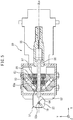
FIG. 5 is a schematic longitudinal sectional view of the intermediate guide device similar toFIG. 4 , but where the guide part is in a closed state. -
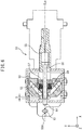
FIG. 6 is a schematic longitudinal sectional view of the intermediate guide device similar toFIG. 5 where the guide part is in the closed state, while the guide part grips an electrode thicker than a predetermined diameter. - The overall configuration of a small-hole electric discharge machining machine according to an embodiment of the present invention (hereinafter referred to as an "electric discharge machining machine") will be explained below while referring to
FIGS. 1 and2 .FIG. 1 is a schematic front view of the electricdischarge machining machine 30 according to the present embodiment, whileFIG. 2 is an enlarged perspective view of principal parts of the electricdischarge machining machine 30. In the electricdischarge machining machine 30 of the present embodiment, as machine coordinates, the mutually perpendicular X-axis, Y-axis, and Z-axis are set. In the following explanation, the Z-axial direction will sometimes be called the "up-down direction". - The electric
discharge machining machine 30 includes abed 1 serving as a base and acolumn 2 provided standing at its rear part. On the top surface of thecolumn 2, an X-slider 3 is supported to be able to move in the X-axial direction. On the top surface of the X-slider 3, aram 4 is supported to be able to move in the Y-axial direction. On the front surface of theram 4, aspindle head 5 is supported to be able to move in the Z-axial direction. - On the top surface of the
bed 1, a table 11 is arranged at the front from thecolumn 2. On the top surface of the table 11, a slantedrotary table device 12 is carried. The slantedrotary table device 12 includes a pair ofsupport members 13 arranged at the top surface of the table 11. Between the pair ofsupport members 13, aslanted member 14 supported to be able to turn in the B-axial direction about a pivot axis CLb extending in the Y-axial direction is arranged. On the end face of theslanted member 14, a rotary table 15 supported to be able to rotate in the A-axial direction about a rotation axis CLa vertical to the pivot axis CLb is arranged. - A front end part of a rotating
spindle 6 projects out from the bottom surface of thespindle head 5. At the bottom part of the rotatingspindle 6, an electrode holder 7 (first support part) holding the base end side of anelectrode 10 is attached. Below theelectrode holder 7, anintermediate guide device 50 guiding an intermediate part of the electrode is arranged. Further below that, an electrode guide 8 (second support part) guiding and positioning the front end part of theelectrode 10 is arranged. Between theelectrode holder 7 and theelectrode guide 8, theelectrode 10 is arranged along a rotation axis CL0 of the rotatingspindle 6 extending in the up-down direction. Theintermediate guide device 50 is supported by a grippingarm 9 to be able to move in the up-down direction. Theelectrode guide 8 is gripped at the bottom end part of the grippingarm 9. The grippingarm 9 is supported to be able to move in the up-down direction at abracket 4a provided at a side surface of theram 4. The axis of movement of thegripping arm 9 in the up-down direction will be called the "W-axis". The W-axis of the present embodiment is parallel to the Z-axis. - As the
electrode 10, in the present embodiment, a cylindricalshape pipe electrode 10 is selected. Theelectrode 10 has an outside diameter corresponding to the inside diameter of the hole to be formed. During the electric discharge machining, theelectrode 10 is rotated by for example a high speed such as 1000 rpm about the rotation axis CL0 by rotation of the rotatingspindle 6. Theelectrode 10 is constrained at its intermediate part at theintermediate guide device 50 so that it does not shake when rotating. An end part of theelectrode 10 projecting out from theelectrode guide 8 serves as a machining part for generating the electric discharge. That is, electric discharge machining is performed at the end part of theelectrode 10 facing theworkpiece 20. As the electric discharge machining progresses, the front end of theelectrode 10 is consumed, but thespindle head 5 and grippingarm 9 descend, so the front end of theelectrode 10 can be positioned at a desired position. - Inside the electric
discharge machining machine 30, various types ofelectrodes 10 are stored set withelectrode holders 7 andelectrode guides 8 corresponding to their outside diameters. When changingelectrodes 10, a known method is followed to automatically change to anotherelectrode 10 together with theelectrode holder 7 andelectrode guide 8 by a not shown electrode changing device. - Inside of the
electrode 10, for example water or another machining fluid is supplied. The machining fluid is injected from the bottom end of theelectrode 10. Note that, theelectrode 10 is not limited to a cylindrical shape pipe electrode. A solid electrode may also be used. - At the rotary table 15, a
workpiece 20 is fastened. Around the table 11, amachining tank 17 is provided so as to surround the table 11 and slantedrotary table device 12 as a whole. Themachining tank 17 is formed to be able to move in the up-down direction. When machining the workpiece, as shown by the one-dot chain line, themachining tank 17 rises. As opposed to this, when performing preparatory work or otherwise not machining, themachining tank 17 descends as shown by the solid line. - The electric
discharge machining machine 30 is configured so that theelectrode 10 can move relative to theworkpiece 20 in the X-axial direction, Y-axial direction, and Z-axial direction. The electricdischarge machining machine 30 is also configured so that theelectrode 10 is formed to be able to move relative to theworkpiece 20 in the B-axial direction and A-axial direction. The distance between theelectrode guide 8 and the surface of theworkpiece 20 can be adjusted by movement of thegripping arm 9 by an arm drive part. - Next, the
intermediate guide device 50 which the electricdischarge machining machine 30 of the present embodiment comprises will be explained in detail below with reference toFIG. 3 to FIG. 6. FIG. 3 to FIG. 6 are schematic plan views with a cover removed so as to enable understanding of the arrangement of the components at the inside of theintermediate guide device 50. The X-, Y-, and Z-directions of theintermediate guide device 50 used in the explanation relating toFIG. 3 to FIG. 6 are equal to the X-, Y-, and Z-directions of the electricdischarge machining machine 30 fastening the same. Theintermediate guide device 50 has a central axis CLm extending in the X-direction. - The
intermediate guide device 50 in the present embodiment comprises aguide part 51 guiding theelectrode 10, a driving means comprised of anair cylinder 55 for making theguide part 51 move from an open state to a closed state and the reverse, a biasing means comprised ofcoil springs 59 acting on theguide part 51, a movementdirection changing mechanism 60 changing a direction of movement between theair cylinder 55 and guidepart 51 by 90 degrees, and a mountingpart 66 for fastening the movementdirection changing mechanism 60 and fastening to thegripping arm 9 of the electric discharge machining machine. Theguide part 51 can guide anelectrode 10 in the closed state and receive anelectrode 10 from the outside in the open state. - The
guide part 51 comprises two pairs of openable/closable fingers 52 (inFIG. 3 to FIG. 6 , only one pair is shown) at the top and bottom arranged separated from each other in the Z-direction and guidepins 53 fastened tobase parts 52b of thefingers 52.FIG. 3 shows theintermediate guide device 50 when theguide part 51 is in the open state. There, the upper side pair offingers 52 is shown.FIG. 4 also shows theintermediate guide device 50 when theguide part 51 is in the open state. InFIG. 4 , to show the internal structure better, the longitudinal section on the central axis CLm is shown. As a result, inFIG. 4 , the lower side pair offingers 52 is shown. - Note that, in this Description, for simplification of the explanation, the
same reference notation 52 is assigned to each of the two fingers of the symmetrical pair of fingers. Further, the upper side pair of fingers and the lower side pair of fingers differ in direction of projection of the guide pins 53, but have the same outside shapes as each other, so in this Description, again thesame reference notations 52 are assigned for simplification of the explanation. - The two fingers of the pair of
fingers 52 of theguide part 51 have symmetrical overall approximately Z-shapes. They have thebase parts 52b extending parallel to the central axis CLm of theintermediate guide device 50 in the X-direction,front end parts 52a formed withnotches 52d for holding or gripping theelectrode 10, andintermediate parts 52c connecting thebase parts 52b andfront end parts 52a and extending perpendicular to the central axis CLm. At thebase parts 52b of the fingers, holes (not shown) into which rod-shaped finger guides 62 of the movementdirection changing mechanism 60 are inserted are formed in the Y-direction perpendicular to the central axis CLm. Thefingers 52 are formed from a plastic material so as to impart electrical insulating ability and so as to prevent wear of the high speed rotating metal electrodes. - The
notch 52d formed at thefront end part 52a of the finger is formed as a substantially V-shape in thefinger 52 at the lower side of the Y-direction inFIG. 3 and therefore as a substantially inverted V-shape in thefinger 52 at the upper side in the Y-direction (hereinafter referred to as the "substantially V-shape") and has asemicircular notch 52e at the vertex part of the V-shape. In the present embodiment, the angle formed by the two slanted sides of the V-shape is about 90 degrees. The radius of thesemicircular notch 52e is set to 1 mm. - The movement
direction changing mechanism 60 has a rectangular shapedframe 61, four rod-shaped finger guides 62 fastened to theframe 61 and extending in the Y-direction, though only two are shown, aslider 63 having two elongatedholes 63a arranged symmetrically about the central axis CLm and slanted by about 45 degrees (hereinafter referred to as "slantedelongated holes 63a"), theslider 63 arranged to be able to move inside theframe 61 in the X-direction, and astopper part 64 against which a front end of aplunger 56 of theair cylinder 55 abuts when theplunger 56 is extended. Theslider 63 can move in the X-direction not only with respect to theframe 61, but also with respect to theplunger 56 of theair cylinder 55. - In the slanted
elongated holes 63a of the slider, the guide pins 53 sticking out from thebase parts 52b of the fingers are inserted. The widths of the slantedelongated holes 63a are formed slightly larger than the diameters of the guide pins 53 so that the guide pins 53 can smoothly move inside the slantedelongated holes 63a. At the rear part of theslider 63, two spring receiving holes extending in the X-direction for receiving the front end parts of the coil springs 59 are provided symmetrically with respect to the central axis CLm. In the present embodiment, a single slider is provided between theupper side fingers 52 andlower side fingers 52. For this reason, in the slantedelongated holes 63a, not only the guide pins 53 sticking out from thelower side fingers 52, but also the guide pins 53 sticking out from theupper side fingers 52 not shown inFIG. 4 are inserted. - The
stopper part 64 in the present embodiment is formed as astud 64 which is fastened to the front wall of theframe 61. Thestud 64 is arranged on the central axis CLm. Against the end sticking out inwardly from the inner surface of the front wall part of the frame 611, the front end of theplunger 56 of theair cylinder 55 abuts. Thestud 64 is fastened to theframe 61 so as to enable adjustment of the amount by which it sticks out to the inside of theframe 61. - The
air cylinder 55 is fastened to the rear wall part of theframe 61 so that its longitudinal direction axial line is superposed on the central axis CLm of the intermediate guide device. Further, at theair cylinder 55, a not shown air feed pipe is connected. At theplunger 56 of theair cylinder 55, aspring support member 57 is fastened. Thespring support member 57 has a cylindrical mountingpart 57a into which theplunger 56 is inserted and supportparts 57b which extend from the rear end part of the mountingpart 57a symmetrically with respect to the central axis CLm in the Y-direction and support the rear end parts of the coil springs 59. Thespring support member 57 is fastened to theplunger 56 at its mountingpart 57a by afastening screw 58, only the head of which is illustrated, at the front end part of theplunger 56. The head of thefastening screw 58 has a flange part flaring to the outside from the mountingpart 57a of the spring support member. - The coil springs 59, in the present embodiment, are formed by compression coil springs 59. Two are arranged in parallel with the central axis CLm and symmetrically. The coil springs 59 are arranged between the
support parts 57b of the spring support member and theslider 63. - Next, how the
intermediate guide device 50 operates will be explained.FIG. 4 shows when theguide part 51 is in the open state. At this time, theair cylinder 55 makes theplunger 56 retract the most. Theslider 63 is pushed to the front by the coil springs 59, but its front end part is blocked from advancing by the flange part of thefastening screw 58 at the front end of theplunger 56, so it stops at the last retracted position shown inFIG. 4 . The guide pins 53 sticking out from thebase parts 52b of the fingers are positioned at the front sides in the slantedelongated holes 63a of the slider and at the sides near the central axis CLm. - If the
air cylinder 55 makes theplunger 56 extend, that is, makes it advance, theslider 63 advances receiving the force from theplunger 56 through thespring support member 57 and coil springs 59. As theslider 63 advances, the guide pins 53 in the slantedelongated holes 63a move from their initial inside positions to outside positions. Therefore, thebase parts 52b of the fingers are also guided by the finger guides 62 and move from the inside to the outside in the Y-direction and therefore thefront end parts 52a of the fingers move from the initial outside positions to the inside. - As shown in
FIG. 5 , if theair cylinder 55 extends theplunger 56 until theplunger 56 abuts against thestopper part 64, theguide part 51 becomes the closed state. At this time, theslider 63 is at its most advanced position, and the guide pins 53 projecting out from thebase parts 52b of the fingers are positioned at the rear sides in the slantedelongated holes 63a of the slider and the furthest from the central axis CLm. As a result, thefront end parts 52a of the pair of fingers are positioned at the inside most sides and therefore theguide part 51 becomes the closed state. - In the closed state, the
semicircular notches 52e at the top parts of the substantially V-shapednotches 52d of the pair of fingers are combined whereby a circular guide hole is formed. In the present embodiment, the radii of thesemicircular notches 52e are set to 1 mm, so the diameter of the guide hole is 2 mm. Therefore, if selecting an electrode with an outside diameter of 1 mm, as shown inFIG. 5 , a clearance is formed between the inside wall of the guide hole and the electrode. The highspeed rotating electrode 10 is restricted in position in the X-Y plane in the range of the guide hole of theguide part 51 in this closed state and is also guided when moving with respect to theguide part 51 in the Z-direction. - To move the
guide part 51 from the closed state shown inFIG. 5 to the open state shown inFIG. 4 , it is sufficient to retract theplunger 56 of theair cylinder 55. If theplunger 56 retracts, due to the flange of thefastening screw 58 at the front end part of theplunger 56, theslider 63 is moved and retracts to the position shown inFIG. 5 . - When in the closed state shown in
FIG. 5 , the front end of theplunger 56 abuts against thestopper part 64. For this reason, the thrust generated by theair cylinder 55 acts on theframe 61 through thestopper part 64, but does not act on theguide part 51. The force generated by the coil springs 59 is supported by the flange of thefastening screw 58 of the front end of theplunger 56 through theslider 63, so again does not act on theguide part 51. -
FIG. 6 is a sectional view, similar toFIG. 5 , of theintermediate guide device 50 when theguide part 51 is in the closed state, but shows the case where theelectrode 10 is changed to one of a relatively thick outside diameter of 3 mm. Theelectrode 10 inFIG. 6 is gripped by the four slanted sides of the substantially V-shapednotches 52d of the pairs offingers 52. Further, the pairs offingers 52 are moved to the outside from the position shown inFIG. 5 due to thethick electrode 10. For this reason, theslider 63 is retracted from the position shown inFIG. 5 by the distance S. At this time, the front end of theplunger 56 remains abutting against thestopper part 64 and thespring support member 57 is not retracted in position, so the force generated by the coil springs 59 acts on thefingers 52 through theslider 63 and guide pins 53 and therefore acts on theelectrode 10. The highspeed rotating electrode 10 is restricted in position in the X-Y plane by being gripped by thefingers 52 of theguide part 51 in the closed state and is guided when moving with respect to theguide part 51 in the Z-direction as well. - In the present embodiment, when the
guide part 51 is in the closed state, as shown inFIG. 5 , when theelectrode 10 has a diameter thinner than a predetermined diameter of 2 mm equal to the diameter of the guide hole, theelectrode 10 is guided by thefingers 52 in a state with a clearance formed between this and the inside wall of the guide hole. As opposed to this, as shown inFIG. 6 , when theelectrode 10 has the predetermined diameter of a 2 mm or more diameter, theelectrode 10 is guided by being gripped by thefingers 52. At this time, the force generated by the coil springs 59 acts on theelectrode 10 through thefingers 52. - For this reason, according to the
intermediate guide device 50 of the present embodiment, it becomes possible to guide all the electrodes from for example a relatively thin electrode of less than a diameter of 2 mm to a relatively thick electrode of a diameter of 2 mm or more, according to thefingers 52 shown inFIG. 6 , up to a maximum about 5 mm, without changing thefingers 52. When desiring to further thicken thegrippable electrode 10, it is sufficient to enlarge the size of the substantially V-shapednotches 52d formed in the fingers. - According to the
intermediate guide device 50 of the present embodiment, the force generated by theair cylinder 55 is used for movement of theguide part 51 between the open state and closed state, while the force generated by the biasing means comprised of the coil springs 59 is used for gripping theelectrode 10. For this reason, it is possible to make the movementdirection changing mechanism 60 requiring the relatively large force for operation operate sufficiently stably by theair cylinder 55, while it becomes possible to grip theelectrode 10 by the optimum force using the biasing means 59 without regard as to the force required for operation of the movementdirection changing mechanism 60. - Further, according to the
intermediate guide device 50 of the present embodiment, when gripping theelectrode 10, the distance S shown inFIG. 6 becomes greater as theelectrode 10 becomes thicker in diameter, so the force which theelectrode 10 receives from the coil springs 59 also becomes larger. In actuality, theelectrode 10 is often slightly bent. In such a case, it is convenient if the gripping force from thefingers 52 functioning as the means for stopping the rotatingelectrode 10 from shaking increases as theelectrode 10 becomes thicker. - In the above-mentioned embodiment, the
intermediate guide device 50 had twoguide parts 51 separated from each other in the Z-direction, that is, two pairs offingers 52, but an embodiment in which theintermediate guide device 50 has one pair or three pairs or more offingers 52 is also possible. -
- 7 electrode holder
- 8 electrode guide
- 10 electrode
- 30 small-hole electric discharge machining machine
- 50 intermediate guide device
- 51 guide part
- 52 fingers
- 52d notch
- 52e semicircular notch
- 53 guide pins
- 55 air cylinder
- 56 plunger
- 57 spring support member
- 58 fastening screw
- 59 coil spring
- 60 movement direction changing mechanism
- 63 slider
- 64 stopper part
Claims (3)
- A small-hole electric discharge machining machine using a rod-shaped or pipe-shaped electrode to machine a workpiece, comprising:a first support part supporting a base end side of the electrode;a second support part supporting a front end side of the electrode; andan intermediate guide device disposed between the first support part and the second support part and guiding the electrode, the intermediate guide device comprisinga guide part having an open state and closed state and guiding the electrode in the closed state,a driving means making the guide part move between the open state and closed state, andbiasing means biasing the guide part in a closing direction when the guide part is in the closed state.
- The small-hole electric discharge machining machine according to claim 1, wherein the intermediate guide device further comprises a stopper part for receiving a thrust of the driving means so that the thrust does not act on the guide part when the guide part is in the closed state.
- The small-hole electric discharge machining machine according to claim 1 or 2,wherein the guide part of the intermediate guide device comprises a pair of fingers forming the open state and the closed state, the pair of fingers also forming a guide hole for guiding the electrode by notches which they have combining in the closed state,wherein the guide hole is formed so that a clearance is formed between an inside wall of the guide hole and the electrode when the electrode is thinner than a predetermined diameter and so that the electrode abuts against the inside wall of the guide hole when the electrode is thicker than the predetermined diameter, andwherein when the electrode is thicker than the predetermined diameter, the biasing force of the biasing means acts on the electrode through the pair of fingers.
Applications Claiming Priority (1)
| Application Number | Priority Date | Filing Date | Title |
|---|---|---|---|
| PCT/JP2015/067074 WO2016199302A1 (en) | 2015-06-12 | 2015-06-12 | Small-hole electric discharge machining machine |
Publications (2)
| Publication Number | Publication Date |
|---|---|
| EP3308893A1 true EP3308893A1 (en) | 2018-04-18 |
| EP3308893A4 EP3308893A4 (en) | 2019-01-16 |
Family
ID=57503531
Family Applications (1)
| Application Number | Title | Priority Date | Filing Date |
|---|---|---|---|
| EP15894987.5A Withdrawn EP3308893A4 (en) | 2015-06-12 | 2015-06-12 | SMALL HOLE ELECTRIC DISCHARGE MACHINING MACHINE |
Country Status (4)
| Country | Link |
|---|---|
| US (1) | US20200030901A1 (en) |
| EP (1) | EP3308893A4 (en) |
| JP (1) | JP6465972B2 (en) |
| WO (1) | WO2016199302A1 (en) |
Families Citing this family (1)
| Publication number | Priority date | Publication date | Assignee | Title |
|---|---|---|---|---|
| US10953483B2 (en) * | 2017-11-15 | 2021-03-23 | General Electric Company | Tool electrode for and methods of electrical discharge machining |
Family Cites Families (81)
| Publication number | Priority date | Publication date | Assignee | Title |
|---|---|---|---|---|
| US2778925A (en) * | 1955-02-25 | 1957-01-22 | Cincinnati Milling Machine Co | Electrical discharge cutting machine |
| US3497663A (en) * | 1968-03-22 | 1970-02-24 | Ford Motor Co | Electrode feeding mechanism |
| US3604884A (en) * | 1969-04-24 | 1971-09-14 | Essar Corp | Electrode feed control for edm machine |
| US3662142A (en) * | 1969-04-24 | 1972-05-09 | Essar Corp | Edm machine head and hydraulic pressure apparatus |
| US3604080A (en) * | 1970-01-16 | 1971-09-14 | Rca Corp | Method for making an electron-tube grid assembly |
| US4101405A (en) * | 1971-02-19 | 1978-07-18 | Inoue-Japax Research (Ijr) Inc. | Shaping apparatus |
| CH572787A5 (en) * | 1973-06-15 | 1976-02-27 | Charmilles Sa Ateliers | |
| US3939321A (en) * | 1973-11-19 | 1976-02-17 | Lockheed Aircraft Corporation | Portable electrical discharge metalworking machine |
| FR2287302A1 (en) * | 1974-10-08 | 1976-05-07 | Agie Ag Ind Elektronik | METHOD AND DEVICE FOR MANUFACTURING AN ELECTRODE-TOOL |
| CH594477A5 (en) * | 1976-08-20 | 1978-01-13 | Agie Ag Ind Elektronik | |
| IT1076323B (en) * | 1977-01-27 | 1985-04-27 | Camardella Giuseppe | METHOD AND EQUIPMENT FOR THE AUTOMATIC WELDING OF RESISTIVE WIRES ON TERMINALS OF ELECTRIC RESISTORS |
| US4233486A (en) * | 1977-12-26 | 1980-11-11 | Inoue-Japax Research Incorporated | Traveling-wire electrical discharge machine |
| US4215262A (en) * | 1978-03-06 | 1980-07-29 | Conceptual Engineering | Automatic percussion welding apparatus with stud feed |
| US4230926A (en) * | 1978-05-01 | 1980-10-28 | Gaumond William J | Electric discharge machine with mechanism for orbiting the electrode |
| US4285224A (en) * | 1979-01-25 | 1981-08-25 | Shkatov Alexandr S | Electric pulse tube expander |
| JPS5766825A (en) * | 1980-10-14 | 1982-04-23 | Fanuc Ltd | Processing initiating point automatic return system in wire cutting discharge processing machine |
| CH644541A5 (en) * | 1981-09-15 | 1984-08-15 | Charmilles Sa Ateliers | DEVICE FOR SELECTING AND CHANGING A WIRE ELECTRODE ON A CUTTING MACHINE. |
| JPS58165927A (en) * | 1982-03-25 | 1983-10-01 | Inoue Japax Res Inc | Electrode wire for wire cut discharge process |
| JPS5955362A (en) * | 1982-09-21 | 1984-03-30 | Inoue Japax Res Inc | Electric discharge coating device |
| US4574028A (en) * | 1983-02-10 | 1986-03-04 | Interrondo Ag | Apparatus for producing a corrugated sheet |
| JPS59156735U (en) * | 1983-04-04 | 1984-10-20 | 日立精工株式会社 | Wire guide mechanism in wire electrical discharge machine |
| US4618761A (en) * | 1983-09-14 | 1986-10-21 | Inoue-Japax Research Incorporation | Electrode cutting apparatus for wire cut electric discharge machine |
| US4598189A (en) * | 1984-03-28 | 1986-07-01 | Inoue-Japax Research Incorporated | Automatic wire-threading with a tubular electrode in a TW-E machine |
| US5159167A (en) * | 1985-03-29 | 1992-10-27 | Raycon Corporation | Structure for and method of electrical discharge machining |
| DE3520540C2 (en) * | 1985-06-07 | 1987-05-07 | Aktiengesellschaft für industrielle Elektronik AGIE Losone bei Locarno, Losone, Locarno | Wire guide arrangement for guiding a wire electrode of an electrical discharge machine |
| DE3533002A1 (en) * | 1985-09-16 | 1987-03-26 | Agie Ag Ind Elektronik | ELECTROEROSION METHOD AND ELECTROEROSION MACHINE FOR CARRYING OUT THE METHOD |
| US4814573A (en) * | 1986-04-07 | 1989-03-21 | Ex-Cell-O Corporation | Electrical discharge machining apparatus with exchangeable electrode refeed cartridge |
| JPS6339738A (en) * | 1986-08-04 | 1988-02-20 | Inoue Japax Res Inc | Small hole machining device |
| JPS6362614A (en) * | 1986-08-30 | 1988-03-18 | Fanuc Ltd | Wire-cut electric spark machine |
| CH673970A5 (en) * | 1986-10-30 | 1990-04-30 | Charmilles Technologies | |
| FR2610454B1 (en) * | 1987-01-29 | 1989-06-09 | Technomed Int Sa | DEVICE PROVIDING IMPROVED ELECTRICAL CONTACT BETWEEN AN ELECTRICAL CONDUCTOR AND AN ELECTRODE OR AN ELECTRODE-HOLDING ELEMENT; USE OF THIS DEVICE IN ANY DEVICE FOR ADVANCING AN ELECTRODE OR AN ELECTRODE-HOLDING ELEMENT |
| US4782203A (en) * | 1987-04-16 | 1988-11-01 | Raycon Textron Inc. | Wire guide for electric discharge machine |
| EP0295206A1 (en) * | 1987-06-10 | 1988-12-14 | Charmilles Technologies S.A. | Device for mounting tool in different directions |
| US4980531A (en) * | 1987-10-12 | 1990-12-25 | Charmilles Technologies S.A. | Prehesive device for the electrode wire of an EDM cutting machine |
| JP2686796B2 (en) * | 1988-11-28 | 1997-12-08 | 西部電機株式会社 | Automatic wire feeding method for wire electric discharge machine |
| JPH0749172B2 (en) * | 1989-02-04 | 1995-05-31 | 株式会社牧野フライス製作所 | Wire electrode guide method and device for wire electric discharge machine |
| US5420388A (en) * | 1989-03-29 | 1995-05-30 | Charmilles Technologies | Tool-holder and rapid rotary spindle |
| WO1990012672A1 (en) * | 1989-04-27 | 1990-11-01 | Mitsubishi Denki Kabushiki Kaisha | Wire electrode supplying apparatus for wire electric discharge machines |
| EP0444160B1 (en) * | 1989-07-13 | 1996-04-10 | Charmilles Technologies S.A. | Device, standard blanks and standardized electrodes for milling and dye sinking by electroerosion |
| US5237145A (en) * | 1989-12-29 | 1993-08-17 | Mitsubishi Denki K.K. | Wire cut electric discharge machining method |
| WO1991012109A1 (en) * | 1990-02-06 | 1991-08-22 | Citizen Watch Co., Ltd. | Method of and device for working clad plate |
| JPH04300121A (en) * | 1991-03-27 | 1992-10-23 | Fanuc Ltd | Upper guide assembly of wire cut electric discharge machining device |
| US5254835A (en) * | 1991-07-16 | 1993-10-19 | General Electric Company | Robotic welder for nuclear boiling water reactors |
| EP0581493B1 (en) * | 1992-07-31 | 1996-03-06 | Sodick Co., Ltd. | Wire refeeding device and method for wire-cut electroerosion apparatus |
| US5324907A (en) * | 1993-09-03 | 1994-06-28 | B&W Nuclear Service Company | EDM apparatus with a cam arm for moving an electrode |
| CA2102762A1 (en) * | 1993-11-09 | 1995-05-10 | Viljo K. Valavaara | Two-stage pressure cylinder |
| JP2952339B2 (en) * | 1995-02-24 | 1999-09-27 | 株式会社牧野フライス製作所 | Electric discharge machine |
| US5585013A (en) * | 1995-04-07 | 1996-12-17 | Truty; Thomas J. | Electrode guide |
| US5603851A (en) * | 1995-08-14 | 1997-02-18 | Seibu Electric & Machinery Co., Ltd. | Wire cutting electrical discharge machine with wire annealing for threading |
| US5861608A (en) * | 1996-11-07 | 1999-01-19 | Ico, Inc. | EDM cutting machine for precision notching tubulars |
| DE69711557D1 (en) * | 1996-12-06 | 2002-05-08 | System 3R Internat Ab Vaelling | Automatic air pressure controlled tool holder |
| US6007784A (en) * | 1997-07-11 | 1999-12-28 | 3Dt, Inc. | Electric discharge surface treating electrode and system |
| US5908563A (en) * | 1997-08-18 | 1999-06-01 | Ann Arbor Machine Company | Side bore electrode retention device for electric discharge machining |
| DE19882292B4 (en) * | 1998-02-05 | 2006-06-08 | Mitsubishi Denki K.K. | Spark erosive wire cutting machine |
| JP3731786B2 (en) * | 1998-02-19 | 2006-01-05 | 三菱電機株式会社 | Wire electrical discharge machine |
| JP2000094224A (en) * | 1998-09-25 | 2000-04-04 | Brother Ind Ltd | Wire electric discharge machine |
| US6452127B1 (en) * | 1999-02-12 | 2002-09-17 | Raycon Corporation | Multi-electrode EDM machine |
| US6225589B1 (en) * | 1999-03-15 | 2001-05-01 | Stephen Bartok | Electric discharge machining apparatus |
| JP3406860B2 (en) * | 1999-04-21 | 2003-05-19 | 株式会社ソディック | Pipe electrode holder for electric discharge machining |
| US7313989B1 (en) * | 1999-06-11 | 2008-01-01 | Tortolani Jr Kenneth Guy | Parallel jaw locking toggle pliers/wrench |
| US6459063B1 (en) * | 1999-07-08 | 2002-10-01 | Sodick Co., Ltd. | Apparatus for electrodischarge machining |
| US6403911B1 (en) * | 2000-09-22 | 2002-06-11 | Industrial Technology Research Institute | Method and apparatus for the wire cut electric discharge machine |
| GB0113879D0 (en) * | 2001-06-07 | 2001-08-01 | Amchem Ltd | Electrical discharge machining apparatus |
| ES2425553T3 (en) * | 2001-09-11 | 2013-10-16 | Agie Charmilles Sa | Procedure and device for multi-wire EDM machining |
| JP2004090132A (en) * | 2002-08-30 | 2004-03-25 | Fanuc Ltd | Wire electric discharge machine |
| US6791054B1 (en) * | 2003-07-31 | 2004-09-14 | General Electric Company | Electrode holding and dispensing assembly for electrical discharge machining apparatus |
| US7518081B2 (en) * | 2004-01-23 | 2009-04-14 | Mitsubishi Denki Kabushiki Kaisha | Electric discharge machining apparatus |
| JP4572232B2 (en) * | 2005-02-28 | 2010-11-04 | 三菱電機株式会社 | EDM machine |
| CN100594987C (en) * | 2005-08-01 | 2010-03-24 | Abb株式会社 | Electrostatic coating device |
| US20070151954A1 (en) * | 2006-01-05 | 2007-07-05 | General Electric Company | Methods and apparatus for fabricating components |
| US7291800B2 (en) * | 2006-02-23 | 2007-11-06 | United Technologies Corporation | EDM electrode tool holder |
| US7210378B1 (en) * | 2006-07-24 | 2007-05-01 | Lawrence Bibi | Chain pliers with wire stripper |
| US7751172B2 (en) * | 2006-10-18 | 2010-07-06 | Axcelis Technologies, Inc. | Sliding wafer release gripper/wafer peeling gripper |
| US8835792B2 (en) * | 2007-04-10 | 2014-09-16 | The Cleveland Electric Laboratories Company | Metal-sheathed structure stripper |
| CN102133666B (en) * | 2010-01-22 | 2014-08-20 | 通用电气公司 | Cutter joint assembly and processing system |
| US8861171B2 (en) * | 2010-02-10 | 2014-10-14 | Sri International | Electroadhesive handling and manipulation |
| JP4986308B2 (en) * | 2010-04-27 | 2012-07-25 | 株式会社ソディック | Automatic wire-cutting device for wire-cut electrical discharge machine |
| JP5490255B2 (en) * | 2010-11-24 | 2014-05-14 | 三菱電機株式会社 | Wire electrical discharge machining apparatus and semiconductor wafer manufacturing method |
| US20120228991A1 (en) * | 2011-02-07 | 2012-09-13 | Vranish John M | Tape muscle |
| CN103874555B (en) * | 2011-10-13 | 2016-09-07 | 三菱电机株式会社 | Discharging processor for line electrode and its line electrode feeding method |
| JP5276731B1 (en) * | 2012-03-21 | 2013-08-28 | ファナック株式会社 | Wire electric discharge machine with wire electrode cutting mechanism |
-
2015
- 2015-06-12 US US15/735,085 patent/US20200030901A1/en not_active Abandoned
- 2015-06-12 EP EP15894987.5A patent/EP3308893A4/en not_active Withdrawn
- 2015-06-12 WO PCT/JP2015/067074 patent/WO2016199302A1/en not_active Ceased
- 2015-06-12 JP JP2017523074A patent/JP6465972B2/en not_active Expired - Fee Related
Also Published As
| Publication number | Publication date |
|---|---|
| EP3308893A4 (en) | 2019-01-16 |
| US20200030901A1 (en) | 2020-01-30 |
| JPWO2016199302A1 (en) | 2017-12-07 |
| WO2016199302A1 (en) | 2016-12-15 |
| JP6465972B2 (en) | 2019-02-06 |
Similar Documents
| Publication | Publication Date | Title |
|---|---|---|
| CN102729085B (en) | Tool changing device and working machine including tool changing device | |
| CN109715333B (en) | Fine hole electric discharge machine | |
| JP4721898B2 (en) | Electric discharge machine and machining method thereof | |
| EP3144096B1 (en) | Collet assembly | |
| EP2548679A1 (en) | Machine tool | |
| CN106493597A (en) | Lathe | |
| EP3278916B1 (en) | Fine hole electrical discharge machine | |
| JP2016198835A (en) | Support method, processing method, and apparatus for performing these methods | |
| JP3963679B2 (en) | Electric discharge machine | |
| US20160368060A1 (en) | Machine tool | |
| US20200030901A1 (en) | Small-hole electric discharge machining machine | |
| CN103203644B (en) | Composite processor | |
| JP2008200806A (en) | EDM machine | |
| JP2018034259A (en) | Machine Tools | |
| KR101518061B1 (en) | Machine tool that oval processing is available | |
| CN113874148B (en) | Fine hole electrical discharge machine | |
| CN213102952U (en) | Glue dispensing device | |
| JP6796455B2 (en) | Sample stand support | |
| JP2021098237A (en) | Lathe and guide member attachment method of the same | |
| CN119368846B (en) | Wire holding device and electric spark perforating machine | |
| JP2753981B2 (en) | Electric discharge machine | |
| JP3233444U (en) | Tool magazines and machine tools | |
| JP2001150277A (en) | Tool changer | |
| JPH0521301Y2 (en) | ||
| JPH0675809B2 (en) | Machining electrode guide for electrical discharge machining |
Legal Events
| Date | Code | Title | Description |
|---|---|---|---|
| STAA | Information on the status of an ep patent application or granted ep patent |
Free format text: STATUS: THE INTERNATIONAL PUBLICATION HAS BEEN MADE |
|
| PUAI | Public reference made under article 153(3) epc to a published international application that has entered the european phase |
Free format text: ORIGINAL CODE: 0009012 |
|
| STAA | Information on the status of an ep patent application or granted ep patent |
Free format text: STATUS: REQUEST FOR EXAMINATION WAS MADE |
|
| 17P | Request for examination filed |
Effective date: 20171207 |
|
| AK | Designated contracting states |
Kind code of ref document: A1 Designated state(s): AL AT BE BG CH CY CZ DE DK EE ES FI FR GB GR HR HU IE IS IT LI LT LU LV MC MK MT NL NO PL PT RO RS SE SI SK SM TR |
|
| AX | Request for extension of the european patent |
Extension state: BA ME |
|
| DAV | Request for validation of the european patent (deleted) | ||
| DAX | Request for extension of the european patent (deleted) | ||
| A4 | Supplementary search report drawn up and despatched |
Effective date: 20181214 |
|
| RIC1 | Information provided on ipc code assigned before grant |
Ipc: B23H 7/26 20060101ALI20181210BHEP Ipc: B23H 9/14 20060101AFI20181210BHEP |
|
| STAA | Information on the status of an ep patent application or granted ep patent |
Free format text: STATUS: THE APPLICATION IS DEEMED TO BE WITHDRAWN |
|
| 18D | Application deemed to be withdrawn |
Effective date: 20220104 |