EP3308763A1 - Automatic cardiopulmonary resuscitation device - Google Patents
Automatic cardiopulmonary resuscitation device Download PDFInfo
- Publication number
- EP3308763A1 EP3308763A1 EP16807868.1A EP16807868A EP3308763A1 EP 3308763 A1 EP3308763 A1 EP 3308763A1 EP 16807868 A EP16807868 A EP 16807868A EP 3308763 A1 EP3308763 A1 EP 3308763A1
- Authority
- EP
- European Patent Office
- Prior art keywords
- electroencephalogram
- signal
- cardiopulmonary resuscitation
- processing unit
- calculation processing
- Prior art date
- Legal status (The legal status is an assumption and is not a legal conclusion. Google has not performed a legal analysis and makes no representation as to the accuracy of the status listed.)
- Granted
Links
Images


Classifications
-
- A—HUMAN NECESSITIES
- A61—MEDICAL OR VETERINARY SCIENCE; HYGIENE
- A61B—DIAGNOSIS; SURGERY; IDENTIFICATION
- A61B5/00—Measuring for diagnostic purposes; Identification of persons
- A61B5/02—Detecting, measuring or recording for evaluating the cardiovascular system, e.g. pulse, heart rate, blood pressure or blood flow
- A61B5/024—Measuring pulse rate or heart rate
- A61B5/0245—Measuring pulse rate or heart rate by using sensing means generating electric signals, i.e. ECG signals
-
- A—HUMAN NECESSITIES
- A61—MEDICAL OR VETERINARY SCIENCE; HYGIENE
- A61B—DIAGNOSIS; SURGERY; IDENTIFICATION
- A61B5/00—Measuring for diagnostic purposes; Identification of persons
- A61B5/24—Detecting, measuring or recording bioelectric or biomagnetic signals of the body or parts thereof
- A61B5/316—Modalities, i.e. specific diagnostic methods
- A61B5/369—Electroencephalography [EEG]
- A61B5/372—Analysis of electroencephalograms
-
- A—HUMAN NECESSITIES
- A61—MEDICAL OR VETERINARY SCIENCE; HYGIENE
- A61B—DIAGNOSIS; SURGERY; IDENTIFICATION
- A61B5/00—Measuring for diagnostic purposes; Identification of persons
- A61B5/02—Detecting, measuring or recording for evaluating the cardiovascular system, e.g. pulse, heart rate, blood pressure or blood flow
- A61B5/026—Measuring blood flow
-
- A—HUMAN NECESSITIES
- A61—MEDICAL OR VETERINARY SCIENCE; HYGIENE
- A61B—DIAGNOSIS; SURGERY; IDENTIFICATION
- A61B5/00—Measuring for diagnostic purposes; Identification of persons
- A61B5/145—Measuring characteristics of blood in vivo, e.g. gas concentration or pH-value ; Measuring characteristics of body fluids or tissues, e.g. interstitial fluid or cerebral tissue
- A61B5/1455—Measuring characteristics of blood in vivo, e.g. gas concentration or pH-value ; Measuring characteristics of body fluids or tissues, e.g. interstitial fluid or cerebral tissue using optical sensors, e.g. spectral photometrical oximeters
- A61B5/14551—Measuring characteristics of blood in vivo, e.g. gas concentration or pH-value ; Measuring characteristics of body fluids or tissues, e.g. interstitial fluid or cerebral tissue using optical sensors, e.g. spectral photometrical oximeters for measuring blood gases
-
- A—HUMAN NECESSITIES
- A61—MEDICAL OR VETERINARY SCIENCE; HYGIENE
- A61B—DIAGNOSIS; SURGERY; IDENTIFICATION
- A61B5/00—Measuring for diagnostic purposes; Identification of persons
- A61B5/24—Detecting, measuring or recording bioelectric or biomagnetic signals of the body or parts thereof
- A61B5/25—Bioelectric electrodes therefor
- A61B5/279—Bioelectric electrodes therefor specially adapted for particular uses
- A61B5/28—Bioelectric electrodes therefor specially adapted for particular uses for electrocardiography [ECG]
- A61B5/282—Holders for multiple electrodes
-
- A—HUMAN NECESSITIES
- A61—MEDICAL OR VETERINARY SCIENCE; HYGIENE
- A61B—DIAGNOSIS; SURGERY; IDENTIFICATION
- A61B5/00—Measuring for diagnostic purposes; Identification of persons
- A61B5/24—Detecting, measuring or recording bioelectric or biomagnetic signals of the body or parts thereof
- A61B5/316—Modalities, i.e. specific diagnostic methods
- A61B5/369—Electroencephalography [EEG]
- A61B5/372—Analysis of electroencephalograms
- A61B5/374—Detecting the frequency distribution of signals, e.g. detecting delta, theta, alpha, beta or gamma waves
-
- A—HUMAN NECESSITIES
- A61—MEDICAL OR VETERINARY SCIENCE; HYGIENE
- A61B—DIAGNOSIS; SURGERY; IDENTIFICATION
- A61B5/00—Measuring for diagnostic purposes; Identification of persons
- A61B5/48—Other medical applications
- A61B5/4836—Diagnosis combined with treatment in closed-loop systems or methods
-
- A—HUMAN NECESSITIES
- A61—MEDICAL OR VETERINARY SCIENCE; HYGIENE
- A61B—DIAGNOSIS; SURGERY; IDENTIFICATION
- A61B5/00—Measuring for diagnostic purposes; Identification of persons
- A61B5/68—Arrangements of detecting, measuring or recording means, e.g. sensors, in relation to patient
- A61B5/6801—Arrangements of detecting, measuring or recording means, e.g. sensors, in relation to patient specially adapted to be attached to or worn on the body surface
- A61B5/6813—Specially adapted to be attached to a specific body part
- A61B5/6814—Head
-
- A—HUMAN NECESSITIES
- A61—MEDICAL OR VETERINARY SCIENCE; HYGIENE
- A61B—DIAGNOSIS; SURGERY; IDENTIFICATION
- A61B5/00—Measuring for diagnostic purposes; Identification of persons
- A61B5/68—Arrangements of detecting, measuring or recording means, e.g. sensors, in relation to patient
- A61B5/6801—Arrangements of detecting, measuring or recording means, e.g. sensors, in relation to patient specially adapted to be attached to or worn on the body surface
- A61B5/6813—Specially adapted to be attached to a specific body part
- A61B5/6824—Arm or wrist
-
- A—HUMAN NECESSITIES
- A61—MEDICAL OR VETERINARY SCIENCE; HYGIENE
- A61B—DIAGNOSIS; SURGERY; IDENTIFICATION
- A61B5/00—Measuring for diagnostic purposes; Identification of persons
- A61B5/70—Means for positioning the patient in relation to the detecting, measuring or recording means
- A61B5/702—Posture restraints
-
- A—HUMAN NECESSITIES
- A61—MEDICAL OR VETERINARY SCIENCE; HYGIENE
- A61B—DIAGNOSIS; SURGERY; IDENTIFICATION
- A61B5/00—Measuring for diagnostic purposes; Identification of persons
- A61B5/72—Signal processing specially adapted for physiological signals or for diagnostic purposes
- A61B5/7271—Specific aspects of physiological measurement analysis
- A61B5/7282—Event detection, e.g. detecting unique waveforms indicative of a medical condition
-
- A—HUMAN NECESSITIES
- A61—MEDICAL OR VETERINARY SCIENCE; HYGIENE
- A61H—PHYSICAL THERAPY APPARATUS, e.g. DEVICES FOR LOCATING OR STIMULATING REFLEX POINTS IN THE BODY; ARTIFICIAL RESPIRATION; MASSAGE; BATHING DEVICES FOR SPECIAL THERAPEUTIC OR HYGIENIC PURPOSES OR SPECIFIC PARTS OF THE BODY
- A61H31/00—Artificial respiration by a force applied to the chest; Heart stimulation, e.g. heart massage
- A61H31/004—Heart stimulation
- A61H31/006—Power driven
-
- A—HUMAN NECESSITIES
- A61—MEDICAL OR VETERINARY SCIENCE; HYGIENE
- A61N—ELECTROTHERAPY; MAGNETOTHERAPY; RADIATION THERAPY; ULTRASOUND THERAPY
- A61N1/00—Electrotherapy; Circuits therefor
- A61N1/18—Applying electric currents by contact electrodes
- A61N1/32—Applying electric currents by contact electrodes alternating or intermittent currents
- A61N1/38—Applying electric currents by contact electrodes alternating or intermittent currents for producing shock effects
- A61N1/39—Heart defibrillators
- A61N1/3904—External heart defibrillators [EHD]
- A61N1/39044—External heart defibrillators [EHD] in combination with cardiopulmonary resuscitation [CPR] therapy
-
- A—HUMAN NECESSITIES
- A61—MEDICAL OR VETERINARY SCIENCE; HYGIENE
- A61B—DIAGNOSIS; SURGERY; IDENTIFICATION
- A61B2505/00—Evaluating, monitoring or diagnosing in the context of a particular type of medical care
- A61B2505/01—Emergency care
-
- A—HUMAN NECESSITIES
- A61—MEDICAL OR VETERINARY SCIENCE; HYGIENE
- A61B—DIAGNOSIS; SURGERY; IDENTIFICATION
- A61B5/00—Measuring for diagnostic purposes; Identification of persons
- A61B5/24—Detecting, measuring or recording bioelectric or biomagnetic signals of the body or parts thereof
- A61B5/316—Modalities, i.e. specific diagnostic methods
- A61B5/318—Heart-related electrical modalities, e.g. electrocardiography [ECG]
- A61B5/346—Analysis of electrocardiograms
- A61B5/349—Detecting specific parameters of the electrocardiograph cycle
- A61B5/361—Detecting fibrillation
-
- A—HUMAN NECESSITIES
- A61—MEDICAL OR VETERINARY SCIENCE; HYGIENE
- A61H—PHYSICAL THERAPY APPARATUS, e.g. DEVICES FOR LOCATING OR STIMULATING REFLEX POINTS IN THE BODY; ARTIFICIAL RESPIRATION; MASSAGE; BATHING DEVICES FOR SPECIAL THERAPEUTIC OR HYGIENIC PURPOSES OR SPECIFIC PARTS OF THE BODY
- A61H2205/00—Devices for specific parts of the body
- A61H2205/08—Trunk
- A61H2205/084—Chest
-
- A—HUMAN NECESSITIES
- A61—MEDICAL OR VETERINARY SCIENCE; HYGIENE
- A61H—PHYSICAL THERAPY APPARATUS, e.g. DEVICES FOR LOCATING OR STIMULATING REFLEX POINTS IN THE BODY; ARTIFICIAL RESPIRATION; MASSAGE; BATHING DEVICES FOR SPECIAL THERAPEUTIC OR HYGIENIC PURPOSES OR SPECIFIC PARTS OF THE BODY
- A61H2230/00—Measuring physical parameters of the user
- A61H2230/08—Other bio-electrical signals
- A61H2230/10—Electroencephalographic signals
- A61H2230/105—Electroencephalographic signals used as a control parameter for the apparatus
-
- A—HUMAN NECESSITIES
- A61—MEDICAL OR VETERINARY SCIENCE; HYGIENE
- A61H—PHYSICAL THERAPY APPARATUS, e.g. DEVICES FOR LOCATING OR STIMULATING REFLEX POINTS IN THE BODY; ARTIFICIAL RESPIRATION; MASSAGE; BATHING DEVICES FOR SPECIAL THERAPEUTIC OR HYGIENIC PURPOSES OR SPECIFIC PARTS OF THE BODY
- A61H2230/00—Measuring physical parameters of the user
- A61H2230/20—Blood composition characteristics
- A61H2230/207—Blood composition characteristics partial O2-value
- A61H2230/208—Blood composition characteristics partial O2-value used as a control parameter for the apparatus
-
- A—HUMAN NECESSITIES
- A61—MEDICAL OR VETERINARY SCIENCE; HYGIENE
- A61H—PHYSICAL THERAPY APPARATUS, e.g. DEVICES FOR LOCATING OR STIMULATING REFLEX POINTS IN THE BODY; ARTIFICIAL RESPIRATION; MASSAGE; BATHING DEVICES FOR SPECIAL THERAPEUTIC OR HYGIENIC PURPOSES OR SPECIFIC PARTS OF THE BODY
- A61H31/00—Artificial respiration by a force applied to the chest; Heart stimulation, e.g. heart massage
- A61H31/008—Supine patient supports or bases, e.g. improving air-way access to the lungs
Definitions
- the present invention relates to a cardiopulmonary resuscitation device that measures electrocardiogram and oxygen saturation during a cardiopulmonary resuscitation procedure, detects brain activity in real time which is a degree of blood circulation to the brain by measuring electroencephalogram, is equipped with a defibrillation function, uses a brain activation index as a CPR signal indicating a degree of cardiopulmonary resuscitation, and is capable of bio signal remote monitoring in a pre-hospital step.
- Cardiopulmonary resuscitation is an emergency treatment method that helps breathing by artificially circulating blood when a heart attack (cardiac arrest) occurs, and when an acute cardiac arrest that suddenly stops the heart of a patient occurs, cardiopulmonary resuscitation must be performed as a first aid. That is, simultaneously performing artificial respiration and cardiac compression (heart massage) is called cardiopulmonary resuscitation.
- the general cardiopulmonary resuscitation recovers around 20% of the normal blood flow, but when the automated external defibrillator (AED) is used, a 100% recovery is possible, and the AED can increase the survival rate of a cardiac arrest patient up to 70%.
- AED automated external defibrillator
- the automated external defibrillator is configured as a device for performing cardiopulmonary resuscitation, and generally AED is configured to automatically shock a patient by checking the heart condition of patient.
- a heart attack occurs, blood circulation to the whole body is interrupted so that if appropriate measures are not taken right away, a patient may die or a serious brain damage may occur.
- the brain begins to be irreversibly injured even when blood supply is interrupted for 4 to 5 minutes, if blood is not supplied to the brain for 6 minutes or more, the functions of the brain and all organs of a patient are stopped, and the patient may die.
- the conventional auto cardiopulmonary resuscitation device detects the chest compression rate and uses it as a CPR signal which indicates the degree of cardiopulmonary resuscitation.
- detecting brain activity can be a more accurate detection method for the degree of cardiopulmonary resuscitation.
- an auto cardiopulmonary resuscitation device which measures electrocardiogram, oxygen saturation, and also electroencephalogram, detects brain activity which is the degree of blood circulation in the brain by using the measured electroencephalogram, remotely sends the detected data to a medical professional, and performs electric shock using a built-in automated external defibrillator in dangerous situations, while performing cardiopulmonary resuscitation.
- an auto cardiopulmonary resuscitation device which is equipped with devices for detection, calculation, and transmission of electrocardiogram, oxygen saturation, and brain activity, and an automatic defibrillator.
- Korean Laid-Open Patent Publication No. 10-2011-0014186 relates to a device for cardiopulmonary resuscitation (CPR) including a chest compression unit, and this chest compression unit includes a plunger located in housing and an electric motor control unit, and the plunger is operated in a reciprocating-motion manner by a reversible electric motor or by a linear flow electric motor, and the electric motor control unit calculates the pressure applied by the plunger and controls the displacement of the plunger based on this pressure.
- CPR cardiopulmonary resuscitation
- the electric motor control unit can receive oxygen saturation, ECG data, EEG data, etc., and these data are used for electric motor control. It is stated that it is possible to control the management of defibrillation pulse and to interlock it.
- Korean Laid-Open Patent Publication No. 10-2011-0014186 does not disclose any details regarding calculation processes used for oxygen saturation, ECG data, EEG data, etc., parameters that are extracted by the calculation processes, and methods of using extracted data to control an electric motor or automated external defibrillator by, and in addition, this cardiopulmonary resuscitation device does not include a device for detecting and analyzing oxygen saturation, ECG, and EEG.
- the problem that the present invention intends to solve is to provide an auto cardiopulmonary resuscitation device which measures electrocardiogram and oxygen saturation during a cardiopulmonary resuscitation procedure, detects brain activity in real time which is a degree of blood circulation to the brain by measuring electroencephalogram, is equipped with a defibrillation function, uses a brain activation index as a CPR signal indicating a degree of cardiopulmonary resuscitation, and is capable of bio ( in vivo) signal remote monitoring in a pre-hospital step.
- the problem that the present invention intends to solve is to provide an auto cardiopulmonary resuscitation device which uses a brain activation index as a CPR signal indicating the degree of cardiopulmonary resuscitation and displays the brain activation index as a CPR signal (CPR feedback information) by waveform or numerical values on a monitor unit of the auto cardiopulmonary resuscitation device.
- the problem that the present invention intends to solve is to provide an auto cardiopulmonary resuscitation device which uses a brain activation index as a CPR signal indicating the degree of cardiopulmonary resuscitation, and also the brain activation index uses a BSR, beta ratio, and SynchFastSlow (SFS).
- a brain activation index as a CPR signal indicating the degree of cardiopulmonary resuscitation
- the brain activation index uses a BSR, beta ratio, and SynchFastSlow (SFS).
- Another problem that the present invention intends to solve is to provide an auto cardiopulmonary resuscitation device that is equipped with devices which detect electrocardiogram, oxygen saturation, and brain activity, and send data detected by these devices remotely to a medical professional, and is equipped with an automated external defibrillator configured to be able to perform electric shock using a built-in automated external defibrillator in a dangerous situation.
- Another problem that the present invention intends to solve is to provide an auto cardiopulmonary resuscitation which calculates and processes oxygen saturation, ECG data, and EEG data to extract parameters and controls an operational motor or an automated defibrillator by using the extracted parameters.
- the cardiopulmonary resuscitation device includes an electroencephalogram detection unit configured to detect an electroencephalogram signal in the frontal lobe; and a calculation processing unit configured to detect a brain activation index from the electroencephalogram signal received from the electroencephalogram detection unit in which the cardiopulmonary resuscitation device uses a brain activation index as a CPR signal indicating a degree of cardiopulmonary resuscitation, and the calculation processing unit calculates one or more of a burst suppression ratio (BSR), a beta ratio, and a relative synchrony of fast and slow wave (SynchFastSlow, SFS) as a brain activation index.
- BSR burst suppression ratio
- beta ratio beta ratio
- SynchronSlow relative synchrony of fast and slow wave
- the calculation processing unit removes a noise in a electroencephalogram signal received by the electroencephalogram detection unit, passes the electroencephalogram signal in which the noise is removed through a 1 Hz low pass filter, performs correction by excluding the signal that passed through the 1 Hz low pass filter in the electroencephalogram signal in which the noise has been removed, takes a first derivative of the corrected electroencephalogram signal, detects a section in which an amplitude is 5 ⁇ V or less for 0.5 sec or more as a suppression (flat brain wave), and thereby detects BSR.
- spectral power (30-47Hz) is a power spectrum at a frequency of 30 to 47 Hz in electroencephalogram, and spectral power (11-20Hz) is a power spectrum at a frequency of 11 to 20Hz).
- bispectral power (0.5-47.0Hz) is a bispectrum calculated in a range of 0.5 Hz and 47.0Hz
- bispectral power (40.0-47.0Hz) is a bispectrum calculated in a range of 40.0Hz and 47.0Hz).
- the calculation processing unit assigns a score according to pre-stored distribution values for each of BSR, beta ratio, and SynchFastSlow (SFS) and adds up assigned scores of BSR, beta ratio, and SynchFastSlow (SFS) to calculate a brain activity.
- the cardiopulmonary resuscitation device includes a main body portion equipped with a chest compression unit configured to pressure a chest of a patient; and a holder configured to support the main body portion wherein the main body portion can be attached thereto or detached therefrom.
- the holder further includes a main body holding unit which is U-shaped and bound to an edge of the main body portion; a holder leg portion which is connected to the main body holding unit to support the main body portion; and a back support portion wherein one end thereof is connected to the holder leg portion as a means of supporting a back of a patient.
- the cardiopulmonary resuscitation device further includes an angle adjusting unit equipped with a hinge between the holder leg portion and back portion in which the angle adjusting unit can be fixed by a stopper.
- the cardiopulmonary resuscitation device further includes a wrist fastening unit configured to fasten and secure a wrist of a patient to left and right sides of the main body holding unit.
- the wrist fastening unit includes any one of an electrocardiogram sensor and oxygen saturation sensor to detect an electrocardiogram signal or oxygen saturation signal to send to the calculation processing unit.
- the back support portion includes an electrocardiogram sensor to detect an electrocardiogram signal to send to the calculation processing unit.
- the electroencephalogram detection unit includes two or four electroencephalogram signal electrodes, and the electroencephalogram detection unit may be headband-formed.
- the cardiopulmonary resuscitation device further includes a monitor unit configured to output a brain activation index.
- the suppression reference amplitude is 5 ⁇ V
- the suppression reference time is 0.5 sec.
- the method further includes an FFT calculation step and a beta ratio calculation step.
- the FFT calculation step is that the calculation processing unit performs FFT to the electroencephalogram signal in which the noise is removed in the noise removing step to calculate a spectral power.
- spectral power (30- 47 Hz) is a power spectrum at a frequency of 30 to 47 Hz in electroencephalogram
- spectral power (11-20 Hz) is a power spectrum at a frequency of 11 to 20 Hz).
- the method further includes a bispectrum calculation step and a SynchFastSlow (SFS) calculation step.
- the bispectrum calculation step is that the calculation processing unit uses a spectral power calculated in the FFT calculation step to calculate a bispectrum in a range of 0.5Hz and 47.0Hz and a bispectrum in a range of 40.0Hz and 47.0Hz.
- the method further includes a brain activity calculation step wherein the calculation processing unit assigns each score for each value of BSR, beta ratio, and SynchFastSlow (SFS) and adds up each assigned score to calculate a brain activity.
- a brain activity calculation step wherein the calculation processing unit assigns each score for each value of BSR, beta ratio, and SynchFastSlow (SFS) and adds up each assigned score to calculate a brain activity.
- the noise removing further includes a band pass filtering step, an independent component analysis step, a template matching step, and an electrooculogram (EOG) signal removing step.
- the band pass filtering step is that the calculation processing unit passes an electroencephalogram signal received from the electroencephalogram detection unit through a band pass filter having a pass band of 0.1Hz to 50Hz.
- the independent component analysis step is that the calculation processing unit separates independent components (source signal) in the electroencephalogram signal passed through the band pass filter according to the independent component analysis (ICA).
- the template matching step is that the calculation processing unit calculates correlation coefficients between a template indicating pre-stored EOG and the independent components, and determines the independent component that a coefficient value of the correlation coefficient exceeds pre-stored reference range of coefficient values as an electrooculogram (EOG) signal.
- the electrooculogram (EOG) signal removing step is that the calculation processing unit removes the electrooculogram (EOG) signal detected by the template matching step in the independent components (source signal) separated by the independent component analysis step.
- the method further includes a motion artifact removing step wherein the calculation processing unit determines as a motion artifact and remove when variance of electroencephalogram signals in which an electrooculogram (EOG) signal is removed in the electrooculogram (EOG) signal removing step, exceeds a pre-stored reference value.
- EOG electrooculogram
- the auto cardiopulmonary resuscitation device measures electrocardiogram and oxygen saturation during a cardiopulmonary resuscitation procedure, detects brain activity in real time which is a degree of blood circulation to the brain by measuring electroencephalogram, is equipped with a defibrillation function, and uses a brain activation index as a CPR signal indicating a degree of cardiopulmonary resuscitation, and therefore, it is possible to provide appropriate treatments to patients in less time so that the rate of resuscitation of patients can be increased
- the present invention uses a brain activation index as a CPR signal indicating the degree of cardiopulmonary resuscitation and displays the brain activation index as a CPR signal (CPR feedback information) by waveform and numerical values on a monitor unit of the auto cardiopulmonary resuscitation device so that even when a user is a beginner, the user can recognize the status of a patient more easily.
- the present invention uses a brain activation index as a CPR signal indicating the degree of cardiopulmonary resuscitation, and also the brain activation index uses a BSR, beta ratio, and SynchFastSlow (SFS) to increase accuracy.
- a brain activation index as a CPR signal indicating the degree of cardiopulmonary resuscitation
- the brain activation index uses a BSR, beta ratio, and SynchFastSlow (SFS) to increase accuracy.
- the auto cardiopulmonary resuscitation device is equipped with devices which detect electrocardiogram, oxygen saturation, and brain activity, and send data detected by these devices remotely to a medical professional, and is equipped with an automated external defibrillator configured to be able to perform electric shock using a built-in automated external defibrillator in a dangerous situation. Therefore, the device is equipped with devices for detecting various bio signals and also composed as a compact instrument equipped with a defibrillator equipped, and since the device can be used easily and rapidly without panic at moments when patients need to be treated fast, not only the rate of resuscitation of a patient can be increased, but also the it is convenient to use the device even in a narrow space like an ambulance.
- the auto cardiopulmonary resuscitation device extracts the parameter by calculating and processing oxygen saturation, ECG data, and EEG data, and controls an operational motor or an automated external defibrillator by using the extracted parameters so that beginners can easily use the device.
- FIG. 1 is an example of the auto cardiopulmonary resuscitation device according to the present invention
- FIG. 2 is a disassembly perspective view in which a main body portion and a holder of the auto cardiopulmonary resuscitation device of FIG. 1 are disassembled
- FIG. 3 is a usage status diagram showing an example of the usage status of the auto cardiopulmonary resuscitation device according to the present invention.
- the auto cardiopulmonary resuscitation device 10 includes a main body portion 100 and a holder 200.
- the main body portion 100 is constituted so as to be detachable from the holder 200 and is equipped with a chest compression adjustment unit 370 so as to operate a chest compression unit 130 to perform chest compression during cardiopulmonary resuscitation.
- One end of the chest compression unit 130 is fitted with a chest compression disc or chest compression suction cup.
- the main body portion 100 receives the extracted electrocardiogram (ECG) signals, oxygen saturation signals, electroencephalogram (EEG, brain wave) signals detected from an electrocardiogram detection unit 310, an oxygen saturation detection unit 320, and an electroencephalogram detection unit 330. Further, the main body portion 100 detects parameters from each extracted signal and sends to a main server 410, and also detects brain activity from brain wave. In addition, the main body portion 100 may further include a defibrillator unit 380. According to circumstances, the main body portion 100 can control a motor operation unit 374 of the chest compression adjusting unit 370 or control the defibrillator unit 380 based on the brain activity.
- ECG electrocardiogram
- EEG electroencephalogram
- an electrocardiogram sensor section (not shown by a diagram) of the electrocardiogram detection unit 310, an oxygen saturation sensor section (not shown by a diagram) of the oxygen saturation detection unit 320, and an electrocardiogram sensor unit (not shown by a diagram) of an electroencephalogram sensor unit 330 (not shown by a diagram) can be constituted so that they can be attached separately to a patient.
- an electrocardiogram sensor unit (not shown by a diagram) and an oxygen saturation sensor unit (not shown by a diagram) can be mounted on the holder 200.
- the electroencephalogram detection unit 330 can be constituted in the form of a headband attached to the head and can be constituted so as to detect electroencephalogram signals in the frontal lobe.
- a convexity 101 is equipped for coupling with a groove 201 of the main body holding unit 210.
- the holder 200 includes a main body holding unit 210, a holder leg portion 220, a back support portion 250, an auxiliary supporting portion 240, and a wrist fastening unit 214.
- the main body holding unit 210 is constituted to be in a U-shaped form as a means for connecting with a side of the main body portion 100 and is connected to a holder leg portion 220. he main body holding unit 210 is equipped with a groove 201 on the inside thereof and the groove 201 is combined with the convexity 101 of the main body portion 100 to fix the main body holding unit 210 and the main body portion 100.
- the support leg portion 220 maintains the main body portion 100 supported by the main body holding unit 210 and is a means of support so that the main body portion 100 and the back support portion 250 are separated by a fixed distance.
- the holder leg portion 220 includes two holder legs, and the neck and head of a patient are inserted (positioned) between the two holder legs.
- an angle adjustment unit 230 is provided and is constituted so that the distance between a bottom (base) of the main body portion 100 (i.e. the base of the chest compression disc or chest compression suction cup) and the back support portion 250, that is, the distance between the bottom of the main body portion 100 (i.e. the base of the chest compression disc or chest compression suction cup) and the chest of a patient, can be adjusted.
- An angle adjusting unit 230 is equipped with a hinge and also with a stopper, and is configured so as to adjust the angle between the main body holding unit 210 and the back support portion 250 for fixing. By doing so, the device can be used by adjusting the angle adjusting unit 230 regardless of whether the patient is an adult, a child, an obese person, or a lean person.
- the back support portion 250 is a board to be placed on the back of a patient.
- the back support portion 250 is constituted with one board, but according to circumstances the one board can be replaced to the separated two boards.
- an electrocardiogram sensor unit (not shown by a diagram) can be located in the back supporting portion.
- An auxiliary support portion 240 is a chest compression belt provided to be connected between the back support portion 250 and the main body portion 100 so as to wrap and compress the chest of a patient and is provided on each of the right and left sides.
- One end of the auxiliary support portion 240 is fixed to the side of the back support portion 250, and the other end of the auxiliary support portion 240 is connected to a ring fixed to the lower side of the main body portion 100 to be fixed thereto.
- a wrist fastening unit 214 is a pair of wrist binding bands for binding and fixing the wrist of a patient.
- the wrist fastening unit 214 is provided on both the left and right sides of the main body holding unit 210 and is configured to fix the wrist of a patient during cardiopulmonary resuscitation, so as not to be disturbed by movements of hands or arms during cardiopulmonary resuscitation.
- the wrist fastening unit can be equipped with an electrocardiogram sensor unit (not shown by a diagram) or oxygen saturation sensor unit (not shown by a diagram).
- FIG. 4 is a block diagram for schematically explaining the configuration of the auto cardiopulmonary resuscitation device 10 according to the present invention and includes an electrocardiogram detection unit 310, an oxygen saturation detection unit 320, an electroencephalogram detection unit 330, an A/D conversion unit 340, a calculation processing unit 350, a chest compression adjusting unit 370, a defibrillator unit 380, a transceiver unit 390, and a monitor unit 395.
- the electrocardiogram detection unit 310 includes an electrocardiogram sensor unit (not shown by a diagram) for detecting an electrocardiogram signal, and an electrocardiogram signal preprocessing unit (not shown by a diagram) for amplifying the electrocardiogram signal detected from the electrocardiogram sensor unit and removing noise.
- the electrocardiogram signal detected by the electrocardiogram detection unit 310 is transmitted to the calculation processing unit 350 via the A/D conversion unit 340.
- An electrocardiogram sensor unit (not shown by a diagram) can be mounted on the back support portion 250 and can be attached to the wrist fastening unit 214, and according to circumstances, it can be separated from an auto cardiopulmonary resuscitation device 10, and equipped with another electrocardiogram sensor unit (not shown by a diagram) placed on the body.
- the oxygen saturation detection unit 320 includes an oxygen saturation sensor unit (not shown by a diagram) for detecting an oxygen saturation signal, and an oxygen saturation signal preprocessing unit (not shown by a diagram) for amplifying an oxygen saturation signal detected by the oxygen saturation sensor unit and removing noise thereof.
- the oxygen saturation signal detected by the oxygen saturation detection unit 320 is transmitted to the calculation processing unit 350 via the A/D conversion unit 340.
- An oxygen saturation sensor unit (not shown by a diagram) is constituted with a light emitting unit and a light receiving unit, and in the light emitting unit, an infrared wavelength light emitting diode (LED) and red wavelength LED are used.
- the oxygen saturation sensor unit can be mounted on the back support portion 250 and can be mounted on the wrist fastening unit 214. According to circumstances, the oxygen saturation sensor unit can be separated from the auto cardiopulmonary resuscitation device 10 to be equipped to a separate oxygen saturation sensor unit (not shown by a diagram) attached on the patient body (for example, a finger, etc.).
- the electroencephalogram detection unit 330 includes an electroencephalogram sensor unit (not shown by a diagram) for detecting an electroencephalogram signal, and an electroencephalogram signal preprocessing unit (not shown) for amplifying the electroencephalogram signal detected from the electroencephalogram sensor unit and removing noise, and the electroencephalogram signal detected by the electroencephalogram detection unit 330 is transmitted to the calculation processing unit 350 via the A/D conversion unit.
- the electroencephalogram detection unit 330 is constituted in a headband type so that a brain electrode can be attached to the frontal lobe, and the electroencephalogram signal detected by the electroencephalogram detection unit 330 can be transmitted to the calculation processing unit 350 by wire or wireless.
- electrocardiogram (ECG) signals, oxygen saturation signals, and electroencephalogram (EEG) signals received from the electrocardiogram detection unit 310, the oxygen saturation detection unit 320, and the electroencephalogram detection unit 330 are converted into digital signals and sent to the calculation processing unit 350.
- the calculation processing unit 350 receives electrocardiogram (ECG) signals, oxygen saturation signals, and electroencephalogram (EEG) signals, detects each parameter by calculation processing.
- the calculation processing unit 350 compares each parameter with each reference value pre-stored in a memory unit (not shown by a diagram) to determine whether it is risk or not. Further, the calculation processing unit 350 sends each parameter obtained calculated from the received electrocardiogram (ECG) signals, oxygen saturation signals, and electroencephalogram EEG signals to a main server (central management center server) 400 or a terminal for medical professionals 410.
- ECG electrocardiogram
- EEG electroencephalogram
- the calculation processing unit 350 detects heart rates, ventricular fibrillation, etc. from electrocardiogram (ECG) signals and detects arterial blood oxygen saturation, venous blood oxygen saturation, an oxygen dissociation (oxygen dissociation curve), etc. from oxygen saturation signals. This is widely known, and a detailed description thereof will be omitted herein.
- ECG electrocardiogram
- the calculation processing unit 350 detects brain activity from electroencephalogram (EEG) signals and determines the degree of cardiopulmonary resuscitation by using the detected brain activity.
- EEG electroencephalogram
- the calculation processing unit 350 determines the degree of cardiopulmonary resuscitation by using the detected brain activity or by using brain activity, heart rates, ventricular fibrillation, arterial blood oxygen saturation, etc., and a motor control signal can be generated which changes chest compression rates based on the degree of cardiopulmonary resuscitation and send it to the chest compression adjusting unit 370.
- the calculation processing unit 350 determines the degree of cardiopulmonary resuscitation by using the detected brain activity or by using brain activity, heart rates, ventricular fibrillation, arterial blood oxygen saturation, etc. and when the degree of cardiopulmonary resuscitation is out of a fixed reference range, a defibrillator control signal can be generated and sent to the defibrillator unit 380.
- the chest compression adjusting unit 370 is a means for controlling the chest compression unit 130 so as to perform chest compression at a predetermined rate and includes a motor operation unit 374 and a motor 377, and is configured to operate a chest compression unit 130 by operating the motor 377 according to the motor control signal received from the calculation processing unit 350.
- the motor operation unit 374 operates the motor 377 according the motor control signal received from the calculation processing unit 350.
- the motor 377 is operated by the motor operation unit 374, and the motor 377 is linked with a plunger of the chest compression unit 130.
- the chest compression unit 130 includes a plunger, and the plunger is operated in the manner of reciprocating motions by the motor 377, that is, a reversible electric motor via a mechanical means for converting rotational motion into linear motion.
- a defibrillator unit 380 is a means for operating a defibrillator and includes a defibrillator operation unit 384 and a defibrillator 387.
- the defibrillator operation unit 384 operates the defibrillator 387 in response to defibrillator control signals of the calculation processing unit 350 or by a user turning on the key of the defibrillator.
- the defibrillator 387 is equipped with a left-side electrode pad and a right-side electrode pad and applies electric shock to the heart of a patient via the left-side electrode pad and right-side electrode pad according to the defibrillator operation unit 384.
- the transceiver unit 390 transmits the electrocardiogram, electroencephalogram, oxygen saturation, brain activity, heart rates, ventricular fibrillation, arterial blood oxygen saturation, etc., received from the calculation processing unit 350 to the main server 400.
- the monitor unit 395 displays electrocardiogram, electroencephalogram, oxygen saturation, brain activity, heart rates, ventricular fibrillation, arterial blood oxygen saturation, etc. received from the calculation processing unit 350. In addition, it displays emergency situations when the degree of cardiopulmonary resuscitation falls outside a fixed reference range. In particular, the monitor unit 395 outputs brain activity or brain activation index (brain activation indicator) as a CPR signal indicating the degree of cardiopulmonary resuscitation.
- brain activity or brain activation index brain activation indicator
- the present invention can further include a respirator (not shown by a diagram), and can further include an additional breathing capacity measuring sensor portion (not shown by a diagram).
- FIG. 5 is a schematic diagram for schematically explaining the signal transfer process of the auto cardiopulmonary resuscitation device and the main server 400 according to the present invention.
- the auto cardiopulmonary resuscitation device 10 receives the electroencephalogram from the electroencephalogram detection unit 330, receives electrocardiogram and oxygen saturation from the electrocardiogram detection unit 310 and the oxygen saturation detection unit 320 mounted on the holder 200, and then calculates brain activity, heart rate, ventricular fibrillation, arterial blood oxygen saturation, etc.
- the auto cardiopulmonary resuscitation device 10 transmits data such as electrocardiogram, electroencephalogram, oxygen saturation, brain activity, heart rate, ventricular fibrillation, arterial blood oxygen saturation, etc. to the main server 400.
- the main server 400 sends the received data to the terminal for medical professionals 410 and transmits the diagnosis of the medical professionals received from the terminal for medical professional 410 to the auto cardiopulmonary resuscitation device 10.
- electrode attachment sites use the internationally unified 10-20 electrode placement method (10-20 system) and can attach multiple electrodes to the frontal lobe part.
- signal electrodes for electroencephalogram detection can be attached to a frontal pole (Fp) of the frontal lobe, that is, Fp1 and Fp2.
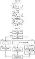
- FIG. 6 shows an example of the headband-type electroencephalogram detection unit according to the present invention.
- FIG. 6(a) shows that the electroencephalogram detection unit 330 is equipped with signal electrodes 331, 332, 337, 338 at Fp1, Fp2, Fp7, Fp8 of the frontal lobe, respectively, and a grounding electrode 333 is provided in the center thereof. According to circumstances, the signal electrode can be attached only Fp1 and Fp2.
- FIG. 6(b) shows that the electroencephalogram detection unit 330 is equipped with signal electrodes 331, 332, 337, 338 at Fp1, Fp2, Fp7, Fp8 of the frontal lobe, respectively, and is equipped with a grounding electrode 333 in one side of the right and left sides, and accordance to circumstances, a reference electrode 334 is provided on one side of the right and left sides. According to circumstances, the signal electrode can be attached only Fp1 and Fp2.
- FIG. 6(c) shows that the electroencephalogram detection unit 330 is equipped with signal electrodes 331, 332, 337, 338 at Fp1, Fp2, Fp7, Fp8 of the frontal lobe, respectively, and at the skull behind the ears on one side of the right and left sides, a grounding electrode 333 is provided, and according to circumstances, a reference electrode 334 is provided at the skull behind the ears on the other one side the right and left sides. In addition, according to circumstances, the signal electrode can be attached only Fp1 and Fp2.
- the headband-type electroencephalogram detection unit of FIG. 6(a) to 6(c) is possible to further include the electroencephalogram detection circuit module 335 that is positioned on one side of the headband.
- the electroencephalogram detection circuit module 335 includes an electroencephalogram signal preprocessing unit (not shown by a diagram) and an electroencephalogram signal transmitter (not shown by a diagram).
- FIG. 6 describes an electroencephalogram detection unit of the headband type, this is not intended to limit the present invention, and according to circumstances, the electroencephalogram detection unit can be constituted as a disposable adhesive patch type so that it can be used by attaching to the frontal lobe of a patient.
- FIG. 7 is a flowchart for schematically explaining a process of detecting a brain activity at the calculation processing unit of FIG. 4 .
- the calculation processing unit 350 removes a noise in the electroencephalogram signal (brain wave signal) received from the A/D conversion unit 340.
- the calculation processing unit 350 passes electroencephalogram signals through a bandpass filter (not shown by a diagram) that has a passband of 0.1 Hz to 50 Hz.
- the bandpass filter can be constituted as a tertiary Butterworth filter.
- Independent components that is, source signals
- ICA independent component analysis
- EOG electrooculogram
- the coefficient value of the correlation coefficient exceeds a pre-stored reference range of the coefficient values, it determines the signal as the electrooculogram (EOG) signal and removes the detected electrooculogram (EOG) signal among the independent components.
- EOG electrooculogram
- Calculating the correlation with the independent components and the EOG template, and detecting the electrooculogram (EOG) signal among independent components (that is, source signals) based on the coefficient value may say to be a template matching.
- processing is carried out by applying the independent component analysis (ICA) method for the electroencephalogram signal that has passed through the above band pass filter to detect a mixed matrix and four independent components (i.e., source signals). Further, the channel of EOG signals among the four independent components (i.e., 4 source signal channels) is detected by pattern matching between EOG signal features of the EOG template (i.e., reference EOG or EOG signal features with square waves) and the four independent components.
- ICA independent component analysis
- motion artifacts which are noises by the motion of patient, are removed in the electroencephalogram signals that are removed the electrooculogram (EOG) signal.
- Variance that is, the difference between the current signal value and previous signal value, is calculated in real time in the electroencephalogram signal in which the electrooculogram (EOG) signal has been removed, and if the variance is exceeds a fixed reference value, it determines the signal as a motion artifact and remove it. That is, a section in which variance sharply increases in the electroencephalogram signal in which the electrooculogram (EOG) signal has been removed is detected and removed.
- an electroencephalogram signal (raw-wave signal) in which noise has been removed in the noise removing step S120 is passed through a 1 Hz low pass filter so as to consider baseline wandering, and suppression detection (flat brain wave detection) is carried out.
- flat brain wave is a section that the amplitude maintains at a 5 ⁇ V or less for 0.5 sec or more, but when these criteria are suddenly applied to electroencephalogram raw-wave signals (i.e., original electroencephalogram signal), suppression cannot be accurately obtained by base line drift. Therefore, the correction as described above is performed. Peak detection is performed based on the first derivative of this waveform to calculate the amplitude of the appearance, and calculate burst suppression ratio (BSR, ratio of burst to flat brain wave ratio) by applying the criteria (i.e., definitions) of the burst suppression.
- BSR burst suppression ratio
- the moving average is the simplest low pass filter, which becomes a low cut filter when moving average is subtracted.
- suppression (flat brain wave) detected in the suppression detection step S130 is used in the electroencephalogram signal corrected in the suppression detection step S130 and is used to detect burst flat brain wave ratio (BSR).
- BSR burst flat brain wave ratio
- the burst flat brain wave ratio is calculated as the ratio of a burst (brain wave with high potential at high frequency) to suppression (brain wave with low potential, flat brain wave) detected at the suppression detection step S130.
- it is determined as a burst when a voltage having a pre-stored burst reference amplitude or more lasts for a burst reference time or longer, and it is determined as suppression when the voltage having a pre-stored suppression reference amplitude below lasts for a suppression reference time or longer, and then the ratio of time interval of the burst and the time interval of the suppression can be obtained.
- the total time interval of bursts and the total time interval of suppression in a given time interval can be obtained.
- BSR can be a value in which the total time interval of suppression is divided by the total time interval of burst, and expressed as a percentage.
- the burst flat brain wave ratio is detected by the ratio of the suppressions (flat brain waves) detected in the suppression detection step S130.
- it is determined as a suppression when the voltage having a suppression reference amplitude or more lasts for a suppression reference time or longer, and the ratio occupied by the suppression time during the measurement time of the brain wave can be obtained.
- BSR can be value in which the total time of suppression during a given time is divided by the brain wave measurement time and is expressed as a percentage.
- QUAZI also called QUAZI suppression rate
- QUAZI can use the data obtained by performing the power spectrum analysis for the electroencephalogram signals. Burst and suppression (flat brain wave) are detected according to a predetermined standard (that is, the stored QUAZI discrimination standard) in the waveform obtained by removing component with a frequency of 1 Hz or less from the electroencephalogram signal (raw-wave signal) to obtain the ratio of the time.
- a predetermined standard that is, the stored QUAZI discrimination standard
- QUAZI is used to quantify a little lower level, that is, a pre-burst state, than when burst and suppression appears in BSR.
- QUAZI inhibition rate
- QUAZI is an index (indicator) used when the baseline sway is large in the flat part of burst suppression, and mainly used for detecting a deep sleep state.
- an FFT calculation step S150 FFT is performed on the electroencephalogram signal (raw-wave signal) in which noise has been removed in the noise removing step S120 to obtain spectral power.
- the Blackman window function can be used before performing FFT in the FFT calculation step S150.
- Beta Ratio log spectral power 30 ⁇ 47 Hz / spectral power 11 ⁇ 20 Hz
- the spectral power (30-47 Hz) is the power spectrum of the gamma band in the brain wave
- the spectral power (11-20 Hz) is the power spectrum of the beta band.
- the beta ratio may be calculated as the log ratio of the bispectrum peak sum in the 11 to 20 Hz region and the bispectrum peak sum in the 30 to 47 Hz region.
- bispectrum is calculated in the range of 0.5 Hz and 47.0 Hz, and in addition, bispectrum is calculated in the range of 40.0 Hz and 47.0 Hz.
- phase coupling a nonlinear interaction of a waveform having two different frequencies.
- the input is the sum of two cosine functions of frequencies that are f1 and f2, and the respective phases are q1 and q2, and the output function at this time is as follows.
- the frequency components of f1 + f2, f1 - f2, 2f1, and 2f2 are dependent on the components of the frequencies of f1 and f2.
- the components created by these nonlinear equations are called intermodulation products (IMPs).
- IMPs intermodulation products
- the phase depends on the phase of original components as shown by the above equations.
- IMP components are expressed as phase-couple.
- components that are not IMPs are called fundamental.
- Bispectral analysis is an interpretation method for examining the existence and extent of the phase-coupled components of the signal component. If it is a linear combination of waves having other frequencies and existing waves, it can be decomposed into individual frequency components by the power spectral analysis.
- bispectral analysis sets the f1 wave and the f2 wave to X(f1) and X(f2), respectively, the phase thereof can be set as f1t + q1 and f2t + q2, and the phase of the wave of f1 + f2 can be (f1+f2)t+q3.
- Wave is represented by a two-dimensional parameter generally called size and phase which are shown as a complex number.
- the phase of X * (f 1 + f 2) is the inversion of the phase of X (f 1 + f 2). That is, - ⁇ (f1 + f2) t + q3 ⁇ .
- phase of the triple product is distributed randomly to (0, 2 p] (where P is an integer).
- P is an integer.
- the size of the sum of the triple product (bispectrum) becomes close to zero.
- a bias occurs in the phase of the triple product having some relation between these three phases, and as a result, the bispectrum has a value other than 0. Bispectral analysis is to investigate phase coupling in this manner.
- the bispectral power (0.5 - 47.0 Hz) is the bispectrum calculated in the range of 0.5 Hz and 47.0 Hz
- the bispectral power (40.0 - 47.0 Hz) is the calculated bispectrum in the range of 40.0 Hz and 47.0 Hz.
- SynchFastSlow can also be obtained as the log ratio of the bispectrum peak sum in the range of 40.0 Hz and 47.0 Hz (i.e., 40 - 47 Hz region) to the bispectrum peak sum in the range of 0.5 Hz and 47.0 Hz (i.e., 0.5 - 47 Hz region).
- BSR calculated in the BSR calculation step 140, the beta ratio obtained in the beta ratio calculation step S160, and the SynchFastSlow(SFS) calculated in the SynchFastSlow(SFS) step are used to detect brain activity.
- Each score is assigned based on BSR, beta ratio, and SynchFastSlow (SFS) for brain activity, and brain activity can be obtained by adding these scores, or by taking an average value of these scores.
- BSR score is assigned according to BSR score assigned values pre-stored on memory based on the value of BSR
- beta ratio is also assigned with a beta ratio score based the beta ratio score assignment on pre-stored on memory
- SynchFastSlow is also assigned a score of SynchFastSlow based on the SynchFastSlow assignment values pre-stored on memory.
- brain activity is each assigned with a score according to BSR, beta ratio, SynchFastSlow (SFS), and QUAZI, respectively, and can be determined as a sum of these scores or taking an average value of these scores.
- any one among BSR, beta ratio, and SynchFastSlow (SFS) can be used as brain activity.
- the brain activity obtained in this way is used as a CPR signal in the conventional auto cardiopulmonary resuscitation device, and this CPR signal, that is, brain activity signal, is displayed on the monitor unit 395.
- the calculation processing unit determines the degree of cardiopulmonary resuscitation by CPR signals, that is, brain activity signals, and generates motor control signals for changing chest compression rates according the degree of cardiopulmonary resuscitation, and sends them to the chest compression adjusting unit 370.
- the calculation processing unit 350 determines the degree of cardiopulmonary resuscitation by using the detected CPR signal, that is, brain activity, and when the degree of cardiopulmonary resuscitation falls outside a predetermined reference range, it generates a defibrillator control signal and sends it to the chest compression adjusting unit 370.
- the BSR, beta ratio, SynchFastSlow (SFS), etc. can be regarded as brain activation indexes, scores are assigned according to each of these brain activation indexes, and brain activity is calculated by adding these scores or taking an average value of these scores, and according to circumstances, any one of BSR, beta ratio, and SynchFastSlow (SFS) can be used as brain activity.
- the auto cardiopulmonary resuscitation device measures electrocardiogram and oxygen saturation during a cardiopulmonary resuscitation procedure, detects brain activity in real time which is a degree of blood circulation to the brain by measuring electroencephalogram, is equipped with a defibrillation function, uses a brain activation index as a CPR signal indicating a degree of cardiopulmonary resuscitation, and is capable of in vivo signal remote monitoring in a pre-hospital step. Therefore, the cardiopulmonary resuscitation device can be placed in government offices, schools, family homes, ambulances, etc., to provide appropriate treatments to patients in less time so that the rate of resuscitation of patients can be increased.
Landscapes
- Health & Medical Sciences (AREA)
- Life Sciences & Earth Sciences (AREA)
- Heart & Thoracic Surgery (AREA)
- Engineering & Computer Science (AREA)
- Veterinary Medicine (AREA)
- Public Health (AREA)
- General Health & Medical Sciences (AREA)
- Animal Behavior & Ethology (AREA)
- Biomedical Technology (AREA)
- Physics & Mathematics (AREA)
- Medical Informatics (AREA)
- Molecular Biology (AREA)
- Surgery (AREA)
- Pathology (AREA)
- Biophysics (AREA)
- Cardiology (AREA)
- Psychiatry (AREA)
- Emergency Medicine (AREA)
- Physiology (AREA)
- Psychology (AREA)
- Physical Education & Sports Medicine (AREA)
- Nuclear Medicine, Radiotherapy & Molecular Imaging (AREA)
- Radiology & Medical Imaging (AREA)
- Signal Processing (AREA)
- Critical Care (AREA)
- Epidemiology (AREA)
- Pulmonology (AREA)
- Pain & Pain Management (AREA)
- Rehabilitation Therapy (AREA)
- Optics & Photonics (AREA)
- Spectroscopy & Molecular Physics (AREA)
- Artificial Intelligence (AREA)
- Computer Vision & Pattern Recognition (AREA)
- Hematology (AREA)
- Measurement And Recording Of Electrical Phenomena And Electrical Characteristics Of The Living Body (AREA)
- Percussion Or Vibration Massage (AREA)
- Measurement Of The Respiration, Hearing Ability, Form, And Blood Characteristics Of Living Organisms (AREA)
Abstract

Description
- The present invention relates to a cardiopulmonary resuscitation device that measures electrocardiogram and oxygen saturation during a cardiopulmonary resuscitation procedure, detects brain activity in real time which is a degree of blood circulation to the brain by measuring electroencephalogram, is equipped with a defibrillation function, uses a brain activation index as a CPR signal indicating a degree of cardiopulmonary resuscitation, and is capable of bio signal remote monitoring in a pre-hospital step.
- Cardiopulmonary resuscitation (CPR) is an emergency treatment method that helps breathing by artificially circulating blood when a heart attack (cardiac arrest) occurs, and when an acute cardiac arrest that suddenly stops the heart of a patient occurs, cardiopulmonary resuscitation must be performed as a first aid. That is, simultaneously performing artificial respiration and cardiac compression (heart massage) is called cardiopulmonary resuscitation.
- The general cardiopulmonary resuscitation recovers around 20% of the normal blood flow, but when the automated external defibrillator (AED) is used, a 100% recovery is possible, and the AED can increase the survival rate of a cardiac arrest patient up to 70%.
- The automated external defibrillator (AED) is configured as a device for performing cardiopulmonary resuscitation, and generally AED is configured to automatically shock a patient by checking the heart condition of patient.
- When a heart attack occurs, blood circulation to the whole body is interrupted so that if appropriate measures are not taken right away, a patient may die or a serious brain damage may occur. In particular, the brain begins to be irreversibly injured even when blood supply is interrupted for 4 to 5 minutes, if blood is not supplied to the brain for 6 minutes or more, the functions of the brain and all organs of a patient are stopped, and the patient may die.
- The conventional auto cardiopulmonary resuscitation device detects the chest compression rate and uses it as a CPR signal which indicates the degree of cardiopulmonary resuscitation. However, detecting brain activity can be a more accurate detection method for the degree of cardiopulmonary resuscitation.
- Therefore, an auto cardiopulmonary resuscitation device is desired which measures electrocardiogram, oxygen saturation, and also electroencephalogram, detects brain activity which is the degree of blood circulation in the brain by using the measured electroencephalogram, remotely sends the detected data to a medical professional, and performs electric shock using a built-in automated external defibrillator in dangerous situations, while performing cardiopulmonary resuscitation.
- In particular, it is necessary to use a cardiopulmonary resuscitation device as fast as possible under emergency situations, and it is highly likely that the device is used in a narrow space such as an ambulance, and therefore, an auto cardiopulmonary resuscitation device is desired which is equipped with devices for detection, calculation, and transmission of electrocardiogram, oxygen saturation, and brain activity, and an automatic defibrillator.
- Korean Laid-Open Patent Publication No.
10-2011-0014186 - In Korean Laid-Open Patent Publication No.
10-2011-0014186 - However, Korean Laid-Open Patent Publication No.
10-2011-0014186 - In general, in an emergency situation where a cardiopulmonary resuscitation device is used, people panic, and in such a situation, it is not easy to find measurement devices for oxygen saturation, ECG, and EEG, and take measurements by attaching each electrode of ECG, EEG, etc. to appropriate positions for patients.
- The problem that the present invention intends to solve is to provide an auto cardiopulmonary resuscitation device which measures electrocardiogram and oxygen saturation during a cardiopulmonary resuscitation procedure, detects brain activity in real time which is a degree of blood circulation to the brain by measuring electroencephalogram, is equipped with a defibrillation function, uses a brain activation index as a CPR signal indicating a degree of cardiopulmonary resuscitation, and is capable of bio (in vivo) signal remote monitoring in a pre-hospital step.
- The problem that the present invention intends to solve is to provide an auto cardiopulmonary resuscitation device which uses a brain activation index as a CPR signal indicating the degree of cardiopulmonary resuscitation and displays the brain activation index as a CPR signal (CPR feedback information) by waveform or numerical values on a monitor unit of the auto cardiopulmonary resuscitation device.
- The problem that the present invention intends to solve is to provide an auto cardiopulmonary resuscitation device which uses a brain activation index as a CPR signal indicating the degree of cardiopulmonary resuscitation, and also the brain activation index uses a BSR, beta ratio, and SynchFastSlow (SFS).
- Another problem that the present invention intends to solve is to provide an auto cardiopulmonary resuscitation device that is equipped with devices which detect electrocardiogram, oxygen saturation, and brain activity, and send data detected by these devices remotely to a medical professional, and is equipped with an automated external defibrillator configured to be able to perform electric shock using a built-in automated external defibrillator in a dangerous situation.
- Another problem that the present invention intends to solve is to provide an auto cardiopulmonary resuscitation which calculates and processes oxygen saturation, ECG data, and EEG data to extract parameters and controls an operational motor or an automated defibrillator by using the extracted parameters.
- In order to solve the above problem, the cardiopulmonary resuscitation device according to the present invention includes an electroencephalogram detection unit configured to detect an electroencephalogram signal in the frontal lobe; and a calculation processing unit configured to detect a brain activation index from the electroencephalogram signal received from the electroencephalogram detection unit in which the cardiopulmonary resuscitation device uses a brain activation index as a CPR signal indicating a degree of cardiopulmonary resuscitation, and the calculation processing unit calculates one or more of a burst suppression ratio (BSR), a beta ratio, and a relative synchrony of fast and slow wave (SynchFastSlow, SFS) as a brain activation index.
- The calculation processing unit removes a noise in a electroencephalogram signal received by the electroencephalogram detection unit, passes the electroencephalogram signal in which the noise is removed through a 1 Hz low pass filter, performs correction by excluding the signal that passed through the 1 Hz low pass filter in the electroencephalogram signal in which the noise has been removed, takes a first derivative of the corrected electroencephalogram signal, detects a section in which an amplitude is 5µV or less for 0.5 sec or more as a suppression (flat brain wave), and thereby detects BSR.
- The calculation processing unit removes a noise in an electroencephalogram signal received by the electroencephalogram detection unit and calculates a beta ratio from the electroencephalogram signal in which the noise has been removed according to:

- (Note that spectral power (30-47Hz) is a power spectrum at a frequency of 30 to 47 Hz in electroencephalogram, and spectral power (11-20Hz) is a power spectrum at a frequency of 11 to 20Hz).
- The calculation processing unit removes a noise in an electroencephalogram signal received by the electroencephalogram detection unit and may calculate SynchFastSlow (SFS) from the electroencephalogram signal in which the noise has been removed according to:

- (Note that bispectral power (0.5-47.0Hz) is a bispectrum calculated in a range of 0.5 Hz and 47.0Hz, and bispectral power (40.0-47.0Hz) is a bispectrum calculated in a range of 40.0Hz and 47.0Hz).
- The calculation processing unit assigns a score according to pre-stored distribution values for each of BSR, beta ratio, and SynchFastSlow (SFS) and adds up assigned scores of BSR, beta ratio, and SynchFastSlow (SFS) to calculate a brain activity.
- The cardiopulmonary resuscitation device includes a main body portion equipped with a chest compression unit configured to pressure a chest of a patient; and a holder configured to support the main body portion wherein the main body portion can be attached thereto or detached therefrom.
- The holder further includes a main body holding unit which is U-shaped and bound to an edge of the main body portion; a holder leg portion which is connected to the main body holding unit to support the main body portion; and a back support portion wherein one end thereof is connected to the holder leg portion as a means of supporting a back of a patient.
- The cardiopulmonary resuscitation device further includes an angle adjusting unit equipped with a hinge between the holder leg portion and back portion in which the angle adjusting unit can be fixed by a stopper.
- The cardiopulmonary resuscitation device further includes a wrist fastening unit configured to fasten and secure a wrist of a patient to left and right sides of the main body holding unit.
- The wrist fastening unit includes any one of an electrocardiogram sensor and oxygen saturation sensor to detect an electrocardiogram signal or oxygen saturation signal to send to the calculation processing unit.
- The back support portion includes an electrocardiogram sensor to detect an electrocardiogram signal to send to the calculation processing unit.
- The electroencephalogram detection unit includes two or four electroencephalogram signal electrodes, and the electroencephalogram detection unit may be headband-formed.
- The cardiopulmonary resuscitation device further includes a monitor unit configured to output a brain activation index.
- In addition, the cardiopulmonary resuscitation device according to the present invention that uses a brain activation index as a CPR signal indicating a degree of cardiopulmonary resuscitation includes: an electroencephalogram detection unit configured to detect an electroencephalogram signal in the frontal lobe; and a calculation processing unit configured to detect a brain activation index from the electroencephalogram signal received by the electroencephalogram detection unit; and a method for operating the cardiopulmonary resuscitation device includes: a noise removing step wherein the calculation processing unit removes a noise in an electroencephalogram signal received from the electroencephalogram detection unit; a suppression detection step wherein the calculation processing unit passes the electroencephalogram signal in which the noise is removed through a 1 Hz low pass filter, performs correction by excluding the signal that passed through the 1Hz low pass filter in the electroencephalogram signal in which the noise has been removed, takes a first derivative of the corrected electroencephalogram signal, and detects a section in which an amplitude is equal to or below a suppression reference amplitude for a time equal to or longer than a suppression reference time as a suppression (flat brain wave); and a BSR calculation step wherein the calculation processing unit detects a burst suppression ratio (BSR) using a time interval of suppression in the suppression detection step in the corrected electroencephalogram signal in the suppression detection step.
- Here, the suppression reference amplitude is 5 µV, and the suppression reference time is 0.5 sec.
- The method further includes an FFT calculation step and a beta ratio calculation step. The FFT calculation step is that the calculation processing unit performs FFT to the electroencephalogram signal in which the noise is removed in the noise removing step to calculate a spectral power. The beta ratio calculation step is that the calculation processing unit uses the spectral power calculated in the FFT calculation step to calculate a beta ratio according to:

- (Note that spectral power (30- 47 Hz) is a power spectrum at a frequency of 30 to 47 Hz in electroencephalogram, and spectral power (11-20 Hz) is a power spectrum at a frequency of 11 to 20 Hz).
- The method further includes a bispectrum calculation step and a SynchFastSlow (SFS) calculation step. The bispectrum calculation step is that the calculation processing unit uses a spectral power calculated in the FFT calculation step to calculate a bispectrum in a range of 0.5Hz and 47.0Hz and a bispectrum in a range of 40.0Hz and 47.0Hz. The SynchFastSlow (SFS) calculation step is that the calculation processing unit uses the bispectral power (0.5-47.0Hz) in a range of 0.5Hz and 47.0Hz and the bispectral power (40.0-47.0Hz) in a range of 40.0Hz and 47.0Hz to calculate SynchFastSlow (SFS) according to:

- The method further includes a brain activity calculation step wherein the calculation processing unit assigns each score for each value of BSR, beta ratio, and SynchFastSlow (SFS) and adds up each assigned score to calculate a brain activity.
- The noise removing further includes a band pass filtering step, an independent component analysis step, a template matching step, and an electrooculogram (EOG) signal removing step. The band pass filtering step is that the calculation processing unit passes an electroencephalogram signal received from the electroencephalogram detection unit through a band pass filter having a pass band of 0.1Hz to 50Hz. The independent component analysis step is that the calculation processing unit separates independent components (source signal) in the electroencephalogram signal passed through the band pass filter according to the independent component analysis (ICA). The template matching step is that the calculation processing unit calculates correlation coefficients between a template indicating pre-stored EOG and the independent components, and determines the independent component that a coefficient value of the correlation coefficient exceeds pre-stored reference range of coefficient values as an electrooculogram (EOG) signal. The electrooculogram (EOG) signal removing step is that the calculation processing unit removes the electrooculogram (EOG) signal detected by the template matching step in the independent components (source signal) separated by the independent component analysis step.
- The method further includes a motion artifact removing step wherein the calculation processing unit determines as a motion artifact and remove when variance of electroencephalogram signals in which an electrooculogram (EOG) signal is removed in the electrooculogram (EOG) signal removing step, exceeds a pre-stored reference value.
- The auto cardiopulmonary resuscitation device according to the present invention measures electrocardiogram and oxygen saturation during a cardiopulmonary resuscitation procedure, detects brain activity in real time which is a degree of blood circulation to the brain by measuring electroencephalogram, is equipped with a defibrillation function, and uses a brain activation index as a CPR signal indicating a degree of cardiopulmonary resuscitation, and therefore, it is possible to provide appropriate treatments to patients in less time so that the rate of resuscitation of patients can be increased
- In addition, the present invention uses a brain activation index as a CPR signal indicating the degree of cardiopulmonary resuscitation and displays the brain activation index as a CPR signal (CPR feedback information) by waveform and numerical values on a monitor unit of the auto cardiopulmonary resuscitation device so that even when a user is a beginner, the user can recognize the status of a patient more easily.
- In addition, the present invention uses a brain activation index as a CPR signal indicating the degree of cardiopulmonary resuscitation, and also the brain activation index uses a BSR, beta ratio, and SynchFastSlow (SFS) to increase accuracy.
- In addition, the auto cardiopulmonary resuscitation device according to the present invention is equipped with devices which detect electrocardiogram, oxygen saturation, and brain activity, and send data detected by these devices remotely to a medical professional, and is equipped with an automated external defibrillator configured to be able to perform electric shock using a built-in automated external defibrillator in a dangerous situation. Therefore, the device is equipped with devices for detecting various bio signals and also composed as a compact instrument equipped with a defibrillator equipped, and since the device can be used easily and rapidly without panic at moments when patients need to be treated fast, not only the rate of resuscitation of a patient can be increased, but also the it is convenient to use the device even in a narrow space like an ambulance.
- In addition, the auto cardiopulmonary resuscitation device according to the present invention extracts the parameter by calculating and processing oxygen saturation, ECG data, and EEG data, and controls an operational motor or an automated external defibrillator by using the extracted parameters so that beginners can easily use the device.
-
-
FIG. 1 is an example of the auto cardiopulmonary resuscitation device according to the present invention. -
FIG. 2 is a disassembly perspective view in which a main body portion and a holder of the auto cardiopulmonary resuscitation device ofFIG. 1 are disassembled. -
FIG. 3 is a usage status diagram showing an example of the usage status of the auto cardiopulmonary resuscitation device according to the present invention. -
FIG. 4 is a block diagram for schematically explaining the configuration of the autocardiopulmonary resuscitation device 10 according to the present invention. -
FIG. 5 is a schematic diagram for schematically explaining the signal transfer process of the auto cardiopulmonary resuscitation device and themain server 400 according to the present invention. -
FIG. 6 shows an example of the headband-type electroencephalogram detection unit according to the present invention. -
FIG. 7 is a flowchart for schematically explaining a process of detecting a brain activity at the calculation processing unit ofFIG. 4 . - Hereinafter, the auto cardiopulmonary resuscitation device according to the present invention will be described in detail with reference to the accompanying drawings.
-
FIG. 1 is an example of the auto cardiopulmonary resuscitation device according to the present invention,FIG. 2 is a disassembly perspective view in which a main body portion and a holder of the auto cardiopulmonary resuscitation device ofFIG. 1 are disassembled, andFIG. 3 is a usage status diagram showing an example of the usage status of the auto cardiopulmonary resuscitation device according to the present invention. - The auto
cardiopulmonary resuscitation device 10 includes amain body portion 100 and aholder 200. - The
main body portion 100 is constituted so as to be detachable from theholder 200 and is equipped with a chestcompression adjustment unit 370 so as to operate achest compression unit 130 to perform chest compression during cardiopulmonary resuscitation. One end of thechest compression unit 130 is fitted with a chest compression disc or chest compression suction cup. - In addition, the
main body portion 100 receives the extracted electrocardiogram (ECG) signals, oxygen saturation signals, electroencephalogram (EEG, brain wave) signals detected from anelectrocardiogram detection unit 310, an oxygensaturation detection unit 320, and anelectroencephalogram detection unit 330. Further, themain body portion 100 detects parameters from each extracted signal and sends to amain server 410, and also detects brain activity from brain wave. In addition, themain body portion 100 may further include adefibrillator unit 380. According to circumstances, themain body portion 100 can control a motor operation unit 374 of the chestcompression adjusting unit 370 or control thedefibrillator unit 380 based on the brain activity. - Here, an electrocardiogram sensor section (not shown by a diagram) of the
electrocardiogram detection unit 310, an oxygen saturation sensor section (not shown by a diagram) of the oxygensaturation detection unit 320, and an electrocardiogram sensor unit (not shown by a diagram) of an electroencephalogram sensor unit 330 (not shown by a diagram) can be constituted so that they can be attached separately to a patient. Alternatively, according to circumstances, an electrocardiogram sensor unit (not shown by a diagram) and an oxygen saturation sensor unit (not shown by a diagram) can be mounted on theholder 200. Theelectroencephalogram detection unit 330 can be constituted in the form of a headband attached to the head and can be constituted so as to detect electroencephalogram signals in the frontal lobe. - On a side of the
main body portion 100, aconvexity 101 is equipped for coupling with agroove 201 of the mainbody holding unit 210. - The
holder 200 includes a mainbody holding unit 210, aholder leg portion 220, aback support portion 250, anauxiliary supporting portion 240, and awrist fastening unit 214. - The main
body holding unit 210 is constituted to be in a U-shaped form as a means for connecting with a side of themain body portion 100 and is connected to aholder leg portion 220. he mainbody holding unit 210 is equipped with agroove 201 on the inside thereof and thegroove 201 is combined with theconvexity 101 of themain body portion 100 to fix the mainbody holding unit 210 and themain body portion 100. - The
support leg portion 220 maintains themain body portion 100 supported by the mainbody holding unit 210 and is a means of support so that themain body portion 100 and theback support portion 250 are separated by a fixed distance. Theholder leg portion 220 includes two holder legs, and the neck and head of a patient are inserted (positioned) between the two holder legs. - Between the
holder leg portion 220 and theback support portion 250, anangle adjustment unit 230 is provided and is constituted so that the distance between a bottom (base) of the main body portion 100 (i.e. the base of the chest compression disc or chest compression suction cup) and theback support portion 250, that is, the distance between the bottom of the main body portion 100 (i.e. the base of the chest compression disc or chest compression suction cup) and the chest of a patient, can be adjusted. Anangle adjusting unit 230 is equipped with a hinge and also with a stopper, and is configured so as to adjust the angle between the mainbody holding unit 210 and theback support portion 250 for fixing. By doing so, the device can be used by adjusting theangle adjusting unit 230 regardless of whether the patient is an adult, a child, an obese person, or a lean person. - The
back support portion 250 is a board to be placed on the back of a patient. InFIG. 1 , theback support portion 250 is constituted with one board, but according to circumstances the one board can be replaced to the separated two boards. - By adjusting the space between the two boards, a width can be formed so that the device can used regardless of adults, children, obese people, or lean people. According to circumstances, an electrocardiogram sensor unit (not shown by a diagram) can be located in the back supporting portion.
- An
auxiliary support portion 240 is a chest compression belt provided to be connected between theback support portion 250 and themain body portion 100 so as to wrap and compress the chest of a patient and is provided on each of the right and left sides. One end of theauxiliary support portion 240 is fixed to the side of theback support portion 250, and the other end of theauxiliary support portion 240 is connected to a ring fixed to the lower side of themain body portion 100 to be fixed thereto. - A
wrist fastening unit 214 is a pair of wrist binding bands for binding and fixing the wrist of a patient. Thewrist fastening unit 214 is provided on both the left and right sides of the mainbody holding unit 210 and is configured to fix the wrist of a patient during cardiopulmonary resuscitation, so as not to be disturbed by movements of hands or arms during cardiopulmonary resuscitation. According to circumstances, the wrist fastening unit can be equipped with an electrocardiogram sensor unit (not shown by a diagram) or oxygen saturation sensor unit (not shown by a diagram). -
FIG. 4 is a block diagram for schematically explaining the configuration of the autocardiopulmonary resuscitation device 10 according to the present invention and includes anelectrocardiogram detection unit 310, an oxygensaturation detection unit 320, anelectroencephalogram detection unit 330, an A/D conversion unit 340, acalculation processing unit 350, a chestcompression adjusting unit 370, adefibrillator unit 380, atransceiver unit 390, and amonitor unit 395. - The
electrocardiogram detection unit 310 includes an electrocardiogram sensor unit (not shown by a diagram) for detecting an electrocardiogram signal, and an electrocardiogram signal preprocessing unit (not shown by a diagram) for amplifying the electrocardiogram signal detected from the electrocardiogram sensor unit and removing noise. The electrocardiogram signal detected by theelectrocardiogram detection unit 310 is transmitted to thecalculation processing unit 350 via the A/D conversion unit 340. An electrocardiogram sensor unit (not shown by a diagram) can be mounted on theback support portion 250 and can be attached to thewrist fastening unit 214, and according to circumstances, it can be separated from an autocardiopulmonary resuscitation device 10, and equipped with another electrocardiogram sensor unit (not shown by a diagram) placed on the body. - The oxygen
saturation detection unit 320 includes an oxygen saturation sensor unit (not shown by a diagram) for detecting an oxygen saturation signal, and an oxygen saturation signal preprocessing unit (not shown by a diagram) for amplifying an oxygen saturation signal detected by the oxygen saturation sensor unit and removing noise thereof. The oxygen saturation signal detected by the oxygensaturation detection unit 320 is transmitted to thecalculation processing unit 350 via the A/D conversion unit 340. An oxygen saturation sensor unit (not shown by a diagram) is constituted with a light emitting unit and a light receiving unit, and in the light emitting unit, an infrared wavelength light emitting diode (LED) and red wavelength LED are used. The oxygen saturation sensor unit can be mounted on theback support portion 250 and can be mounted on thewrist fastening unit 214. According to circumstances, the oxygen saturation sensor unit can be separated from the autocardiopulmonary resuscitation device 10 to be equipped to a separate oxygen saturation sensor unit (not shown by a diagram) attached on the patient body (for example, a finger, etc.). - The
electroencephalogram detection unit 330 includes an electroencephalogram sensor unit (not shown by a diagram) for detecting an electroencephalogram signal, and an electroencephalogram signal preprocessing unit (not shown) for amplifying the electroencephalogram signal detected from the electroencephalogram sensor unit and removing noise, and the electroencephalogram signal detected by theelectroencephalogram detection unit 330 is transmitted to thecalculation processing unit 350 via the A/D conversion unit. Theelectroencephalogram detection unit 330 is constituted in a headband type so that a brain electrode can be attached to the frontal lobe, and the electroencephalogram signal detected by theelectroencephalogram detection unit 330 can be transmitted to thecalculation processing unit 350 by wire or wireless. - In the A/
D conversion unit 340, electrocardiogram (ECG) signals, oxygen saturation signals, and electroencephalogram (EEG) signals received from theelectrocardiogram detection unit 310, the oxygensaturation detection unit 320, and theelectroencephalogram detection unit 330 are converted into digital signals and sent to thecalculation processing unit 350. - The
calculation processing unit 350 receives electrocardiogram (ECG) signals, oxygen saturation signals, and electroencephalogram (EEG) signals, detects each parameter by calculation processing. Thecalculation processing unit 350 compares each parameter with each reference value pre-stored in a memory unit (not shown by a diagram) to determine whether it is risk or not. Further, thecalculation processing unit 350 sends each parameter obtained calculated from the received electrocardiogram (ECG) signals, oxygen saturation signals, and electroencephalogram EEG signals to a main server (central management center server) 400 or a terminal formedical professionals 410. - The
calculation processing unit 350 detects heart rates, ventricular fibrillation, etc. from electrocardiogram (ECG) signals and detects arterial blood oxygen saturation, venous blood oxygen saturation, an oxygen dissociation (oxygen dissociation curve), etc. from oxygen saturation signals. This is widely known, and a detailed description thereof will be omitted herein. - In addition, the
calculation processing unit 350 detects brain activity from electroencephalogram (EEG) signals and determines the degree of cardiopulmonary resuscitation by using the detected brain activity. - According to circumstances, the
calculation processing unit 350 determines the degree of cardiopulmonary resuscitation by using the detected brain activity or by using brain activity, heart rates, ventricular fibrillation, arterial blood oxygen saturation, etc., and a motor control signal can be generated which changes chest compression rates based on the degree of cardiopulmonary resuscitation and send it to the chestcompression adjusting unit 370. In addition, thecalculation processing unit 350 determines the degree of cardiopulmonary resuscitation by using the detected brain activity or by using brain activity, heart rates, ventricular fibrillation, arterial blood oxygen saturation, etc. and when the degree of cardiopulmonary resuscitation is out of a fixed reference range, a defibrillator control signal can be generated and sent to thedefibrillator unit 380. - The chest
compression adjusting unit 370 is a means for controlling thechest compression unit 130 so as to perform chest compression at a predetermined rate and includes a motor operation unit 374 and a motor 377, and is configured to operate achest compression unit 130 by operating the motor 377 according to the motor control signal received from thecalculation processing unit 350. - The motor operation unit 374 operates the motor 377 according the motor control signal received from the
calculation processing unit 350. - The motor 377 is operated by the motor operation unit 374, and the motor 377 is linked with a plunger of the
chest compression unit 130. - The
chest compression unit 130 includes a plunger, and the plunger is operated in the manner of reciprocating motions by the motor 377, that is, a reversible electric motor via a mechanical means for converting rotational motion into linear motion. - A
defibrillator unit 380 is a means for operating a defibrillator and includes adefibrillator operation unit 384 and adefibrillator 387. - The
defibrillator operation unit 384 operates thedefibrillator 387 in response to defibrillator control signals of thecalculation processing unit 350 or by a user turning on the key of the defibrillator. - The
defibrillator 387 is equipped with a left-side electrode pad and a right-side electrode pad and applies electric shock to the heart of a patient via the left-side electrode pad and right-side electrode pad according to thedefibrillator operation unit 384. - The
transceiver unit 390 transmits the electrocardiogram, electroencephalogram, oxygen saturation, brain activity, heart rates, ventricular fibrillation, arterial blood oxygen saturation, etc., received from thecalculation processing unit 350 to themain server 400. - The
monitor unit 395 displays electrocardiogram, electroencephalogram, oxygen saturation, brain activity, heart rates, ventricular fibrillation, arterial blood oxygen saturation, etc. received from thecalculation processing unit 350. In addition, it displays emergency situations when the degree of cardiopulmonary resuscitation falls outside a fixed reference range. In particular, themonitor unit 395 outputs brain activity or brain activation index (brain activation indicator) as a CPR signal indicating the degree of cardiopulmonary resuscitation. - According to circumstances, the present invention can further include a respirator (not shown by a diagram), and can further include an additional breathing capacity measuring sensor portion (not shown by a diagram).
-
FIG. 5 is a schematic diagram for schematically explaining the signal transfer process of the auto cardiopulmonary resuscitation device and themain server 400 according to the present invention. - The auto
cardiopulmonary resuscitation device 10 receives the electroencephalogram from theelectroencephalogram detection unit 330, receives electrocardiogram and oxygen saturation from theelectrocardiogram detection unit 310 and the oxygensaturation detection unit 320 mounted on theholder 200, and then calculates brain activity, heart rate, ventricular fibrillation, arterial blood oxygen saturation, etc. The autocardiopulmonary resuscitation device 10 transmits data such as electrocardiogram, electroencephalogram, oxygen saturation, brain activity, heart rate, ventricular fibrillation, arterial blood oxygen saturation, etc. to themain server 400. - The
main server 400 sends the received data to the terminal formedical professionals 410 and transmits the diagnosis of the medical professionals received from the terminal for medical professional 410 to the autocardiopulmonary resuscitation device 10. - In the
electroencephalogram detection unit 330, electrode attachment sites use the internationally unified 10-20 electrode placement method (10-20 system) and can attach multiple electrodes to the frontal lobe part. For example, signal electrodes for electroencephalogram detection can be attached to a frontal pole (Fp) of the frontal lobe, that is, Fp1 and Fp2. -
FIG. 6 shows an example of the headband-type electroencephalogram detection unit according to the present invention. -
FIG. 6(a) shows that theelectroencephalogram detection unit 330 is equipped withsignal electrodes grounding electrode 333 is provided in the center thereof. According to circumstances, the signal electrode can be attached only Fp1 and Fp2. -
FIG. 6(b) shows that theelectroencephalogram detection unit 330 is equipped withsignal electrodes grounding electrode 333 in one side of the right and left sides, and accordance to circumstances, areference electrode 334 is provided on one side of the right and left sides. According to circumstances, the signal electrode can be attached only Fp1 and Fp2. -
FIG. 6(c) shows that theelectroencephalogram detection unit 330 is equipped withsignal electrodes grounding electrode 333 is provided, and according to circumstances, areference electrode 334 is provided at the skull behind the ears on the other one side the right and left sides. In addition, according to circumstances, the signal electrode can be attached only Fp1 and Fp2. - The headband-type electroencephalogram detection unit of
FIG. 6(a) to 6(c) is possible to further include the electroencephalogramdetection circuit module 335 that is positioned on one side of the headband. The electroencephalogramdetection circuit module 335 includes an electroencephalogram signal preprocessing unit (not shown by a diagram) and an electroencephalogram signal transmitter (not shown by a diagram). - Although
FIG. 6 describes an electroencephalogram detection unit of the headband type, this is not intended to limit the present invention, and according to circumstances, the electroencephalogram detection unit can be constituted as a disposable adhesive patch type so that it can be used by attaching to the frontal lobe of a patient. -
FIG. 7 is a flowchart for schematically explaining a process of detecting a brain activity at the calculation processing unit ofFIG. 4 . - In the noise removing step S120, the
calculation processing unit 350 removes a noise in the electroencephalogram signal (brain wave signal) received from the A/D conversion unit 340. - In this noise removing step, first, the
calculation processing unit 350 passes electroencephalogram signals through a bandpass filter (not shown by a diagram) that has a passband of 0.1 Hz to 50 Hz. The bandpass filter can be constituted as a tertiary Butterworth filter. - Independent components (that is, source signals) are separated according to the independent component analysis (ICA) from the electroencephalogram signal that has passed through the band pass filter. In general, when an electroencephalogram (brain wave) signal is detected at the frontal lobe, an electrooculogram (EOG) signal is added in this electroencephalogram signal. Since it is difficult to determine which signal is the electrooculogram (EOG) signal among the independent components (that is, source signals) separated according to the independent component analysis method (ICA), the correlation coefficient between a pre-stored EOG template and the independent components (that is, source signals) is calculated. When the coefficient value of the correlation coefficient exceeds a pre-stored reference range of the coefficient values, it determines the signal as the electrooculogram (EOG) signal and removes the detected electrooculogram (EOG) signal among the independent components. Calculating the correlation with the independent components and the EOG template, and detecting the electrooculogram (EOG) signal among independent components (that is, source signals) based on the coefficient value may say to be a template matching.
- When using four electroencephalogram electrodes (Fp1, Fp2, Fp7, and Fp8), processing is carried out by applying the independent component analysis (ICA) method for the electroencephalogram signal that has passed through the above band pass filter to detect a mixed matrix and four independent components (i.e., source signals). Further, the channel of EOG signals among the four independent components (i.e., 4 source signal channels) is detected by pattern matching between EOG signal features of the EOG template (i.e., reference EOG or EOG signal features with square waves) and the four independent components.
- In addition, motion artifacts which are noises by the motion of patient, are removed in the electroencephalogram signals that are removed the electrooculogram (EOG) signal. Variance, that is, the difference between the current signal value and previous signal value, is calculated in real time in the electroencephalogram signal in which the electrooculogram (EOG) signal has been removed, and if the variance is exceeds a fixed reference value, it determines the signal as a motion artifact and remove it. That is, a section in which variance sharply increases in the electroencephalogram signal in which the electrooculogram (EOG) signal has been removed is detected and removed.
- As a suppression detection step S130, an electroencephalogram signal (raw-wave signal) in which noise has been removed in the noise removing step S120 is passed through a 1 Hz low pass filter so as to consider baseline wandering, and suppression detection (flat brain wave detection) is carried out.
- That is, it is carried out correction by deducting the signal which has passed through the 1 Hz low pass filter from the electroencephalogram signal (raw-signal) in which noise has been removed, and is performed first derivative about the corrected electroencephalogram signal, and detects a section in which the amplitude continuously is 5 µV or less for 0.5 sec or more, as a suppression (flat brain wave). According to circumstances, instead of a 1 Hz low pass filter, it can be taken a moving average of the base line of the above electroencephalogram.
- In general, in the criteria of burst suppression, flat brain wave is a section that the amplitude maintains at a 5 µV or less for 0.5 sec or more, but when these criteria are suddenly applied to electroencephalogram raw-wave signals (i.e., original electroencephalogram signal), suppression cannot be accurately obtained by base line drift. Therefore, the correction as described above is performed. Peak detection is performed based on the first derivative of this waveform to calculate the amplitude of the appearance, and calculate burst suppression ratio (BSR, ratio of burst to flat brain wave ratio) by applying the criteria (i.e., definitions) of the burst suppression. In general, the moving average is the simplest low pass filter, which becomes a low cut filter when moving average is subtracted.
- In a
BSR calculation step 140, suppression (flat brain wave) detected in the suppression detection step S130 is used in the electroencephalogram signal corrected in the suppression detection step S130 and is used to detect burst flat brain wave ratio (BSR). - The burst flat brain wave ratio (BSR) is calculated as the ratio of a burst (brain wave with high potential at high frequency) to suppression (brain wave with low potential, flat brain wave) detected at the suppression detection step S130. In this case, it is determined as a burst when a voltage having a pre-stored burst reference amplitude or more lasts for a burst reference time or longer, and it is determined as suppression when the voltage having a pre-stored suppression reference amplitude below lasts for a suppression reference time or longer, and then the ratio of time interval of the burst and the time interval of the suppression can be obtained. According to circumstances, the total time interval of bursts and the total time interval of suppression in a given time interval can be obtained. According to circumstances, BSR can be a value in which the total time interval of suppression is divided by the total time interval of burst, and expressed as a percentage.
- Alternatively, the burst flat brain wave ratio (BSR) is detected by the ratio of the suppressions (flat brain waves) detected in the suppression detection step S130. In this case, it is determined as a suppression when the voltage having a suppression reference amplitude or more lasts for a suppression reference time or longer, and the ratio occupied by the suppression time during the measurement time of the brain wave can be obtained.
- According to circumstances, BSR can be value in which the total time of suppression during a given time is divided by the brain wave measurement time and is expressed as a percentage.
- In addition, according to circumstances, in
BSR calculation step 140, QUAZI (also called QUAZI suppression rate) which indicates the ratio of pre bursts can be further obtained. QUAZI can use the data obtained by performing the power spectrum analysis for the electroencephalogram signals. Burst and suppression (flat brain wave) are detected according to a predetermined standard (that is, the stored QUAZI discrimination standard) in the waveform obtained by removing component with a frequency of 1 Hz or less from the electroencephalogram signal (raw-wave signal) to obtain the ratio of the time. Here, the predetermined standard (QUAZI criterion), that is, the discrimination standard for burst and suppression (flat brain wave), is lower than the BSR discrimination criteria. That is, QUAZI is used to quantify a little lower level, that is, a pre-burst state, than when burst and suppression appears in BSR. QUAZI (inhibition rate) can predict the present inhibition rate in the currently unstable voltage of a baseline. In general, QUAZI is an index (indicator) used when the baseline sway is large in the flat part of burst suppression, and mainly used for detecting a deep sleep state. - In an FFT calculation step S150, FFT is performed on the electroencephalogram signal (raw-wave signal) in which noise has been removed in the noise removing step S120 to obtain spectral power. According to circumstances, the Blackman window function can be used before performing FFT in the FFT calculation step S150.
- In a beta ratio calculation step S160, using the spectral power in the FFT calculation step S150, the beta ratio is obtained. The beta ratio (Beta Ratio) is obtained by

- Here, the spectral power (30-47 Hz) is the power spectrum of the gamma band in the brain wave, and the spectral power (11-20 Hz) is the power spectrum of the beta band.
- According to circumstances, the beta ratio may be calculated as the log ratio of the bispectrum peak sum in the 11 to 20 Hz region and the bispectrum peak sum in the 30 to 47 Hz region.
- In a bispectrum calculation step S170, bispectrum is calculated in the range of 0.5 Hz and 47.0 Hz, and in addition, bispectrum is calculated in the range of 40.0 Hz and 47.0 Hz. Here, calculating the bispectrum in the range of 0.5 Hz and 47.0 Hz means that bispectrum is calculated at f1 = 0.5 Hz, f2 = 47.0 Hz, and f1 + f2 = 47.5 Hz.
- In additional explanation, bispectral analysis investigates a nonlinear interaction (phase coupling) of a waveform having two different frequencies. As a simple example of phase coupling, a function that returns the square of an input as an output can be mentioned. The input is the sum of two cosine functions of frequencies that are f1 and f2, and the respective phases are q1 and q2, and the output function at this time is as follows.
- INPUT: x(t) = cos(f1t+q1) + cos(f2t+q2)
- OUTPUT: y(t) = 1 + cos[(f1+f2)t+(q1+q2)] + cos[(f1-f2)t+(q1-q2)] +1/2cos(2f1t+2q1) + 1/2cos(2f2t+2q2)
- In this case, the frequency components of f1 + f2, f1 - f2, 2f1, and 2f2 are dependent on the components of the frequencies of f1 and f2. The components created by these nonlinear equations (calculations other than addition/subtraction of inputs) are called intermodulation products (IMPs). As IMPs, the phase depends on the phase of original components as shown by the above equations. These IMP components are expressed as phase-couple. Meanwhile, components that are not IMPs are called fundamental. Bispectral analysis is an interpretation method for examining the existence and extent of the phase-coupled components of the signal component. If it is a linear combination of waves having other frequencies and existing waves, it can be decomposed into individual frequency components by the power spectral analysis. However, in the case of nonlinear coupling, it cannot be interpreted by power spectral analysis. Considering two different frequencies f1 and f2 and the added frequency f1 + f2, bispectral analysis sets the f1 wave and the f2 wave to X(f1) and X(f2), respectively, the phase thereof can be set as f1t + q1 and f2t + q2, and the phase of the wave of f1 + f2 can be (f1+f2)t+q3. Wave is represented by a two-dimensional parameter generally called size and phase which are shown as a complex number. Here, if the conjugate complex number of X (f 1 + f 2) is X * (f 1 + f 2), the phase of X * (f 1 + f 2) is the inversion of the phase of X (f 1 + f 2). That is, - {(f1 + f2) t + q3}. Considering the triple product of the products of X (f 1), X (f 2), and X * (f 1 + f 2), the phase of this triple product is (f 1 t + q 1) + (f 2 t + q 2) - {(f 1 + f 2) t + q 3} = q 1 + q 2 - q 3. If there is no phase coupling between q 1, q 2, and q 3, the phase of the triple product is distributed randomly to (0, 2 p] (where P is an integer). As a result, the size of the sum of the triple product (bispectrum) becomes close to zero. However, a bias occurs in the phase of the triple product having some relation between these three phases, and as a result, the bispectrum has a value other than 0. Bispectral analysis is to investigate phase coupling in this manner.
- In the SynchFastSlow (SFS) calculation step S180, SynchFastSlow (relative synchrony of fast and slow wave, SFS) is obtained by the following equation: SynchFastSlow shall be the ratio of the sizes of the bispectrum of the entire frequency region to the high frequency region from the brain wave.

- Here, the bispectral power (0.5 - 47.0 Hz) is the bispectrum calculated in the range of 0.5 Hz and 47.0 Hz, and the bispectral power (40.0 - 47.0 Hz) is the calculated bispectrum in the range of 40.0 Hz and 47.0 Hz.
- According to circumstances, SynchFastSlow can also be obtained as the log ratio of the bispectrum peak sum in the range of 40.0 Hz and 47.0 Hz (i.e., 40 - 47 Hz region) to the bispectrum peak sum in the range of 0.5 Hz and 47.0 Hz (i.e., 0.5 - 47 Hz region).
- In a brain activity determination step, BSR calculated in the
BSR calculation step 140, the beta ratio obtained in the beta ratio calculation step S160, and the SynchFastSlow(SFS) calculated in the SynchFastSlow(SFS) step are used to detect brain activity. - Each score is assigned based on BSR, beta ratio, and SynchFastSlow (SFS) for brain activity, and brain activity can be obtained by adding these scores, or by taking an average value of these scores. For example, BSR score is assigned according to BSR score assigned values pre-stored on memory based on the value of BSR, beta ratio is also assigned with a beta ratio score based the beta ratio score assignment on pre-stored on memory, and SynchFastSlow is also assigned a score of SynchFastSlow based on the SynchFastSlow assignment values pre-stored on memory.
- According to circumstances, brain activity is each assigned with a score according to BSR, beta ratio, SynchFastSlow (SFS), and QUAZI, respectively, and can be determined as a sum of these scores or taking an average value of these scores.
- Alternatively, any one among BSR, beta ratio, and SynchFastSlow (SFS) can be used as brain activity.
- The brain activity obtained in this way is used as a CPR signal in the conventional auto cardiopulmonary resuscitation device, and this CPR signal, that is, brain activity signal, is displayed on the
monitor unit 395. - In addition, the calculation processing unit determines the degree of cardiopulmonary resuscitation by CPR signals, that is, brain activity signals, and generates motor control signals for changing chest compression rates according the degree of cardiopulmonary resuscitation, and sends them to the chest
compression adjusting unit 370. In addition, thecalculation processing unit 350 determines the degree of cardiopulmonary resuscitation by using the detected CPR signal, that is, brain activity, and when the degree of cardiopulmonary resuscitation falls outside a predetermined reference range, it generates a defibrillator control signal and sends it to the chestcompression adjusting unit 370. - In other words, the BSR, beta ratio, SynchFastSlow (SFS), etc. can be regarded as brain activation indexes, scores are assigned according to each of these brain activation indexes, and brain activity is calculated by adding these scores or taking an average value of these scores, and according to circumstances, any one of BSR, beta ratio, and SynchFastSlow (SFS) can be used as brain activity.
- As described above, although the present invention has been described by way of limited examples and drawings, the present invention is not limited to the above-mentioned embodiments, and various modifications and variations are possible from the disclosure for a person of ordinary skill in the art to which the present invention belongs. Therefore, the spirit of the present invention should be understood only by the scope of the claims set forth below, and all equal or equivalent variations fall within the category of the spirit of the present invention.
- The auto cardiopulmonary resuscitation device according to the present invention measures electrocardiogram and oxygen saturation during a cardiopulmonary resuscitation procedure, detects brain activity in real time which is a degree of blood circulation to the brain by measuring electroencephalogram, is equipped with a defibrillation function, uses a brain activation index as a CPR signal indicating a degree of cardiopulmonary resuscitation, and is capable of in vivo signal remote monitoring in a pre-hospital step. Therefore, the cardiopulmonary resuscitation device can be placed in government offices, schools, family homes, ambulances, etc., to provide appropriate treatments to patients in less time so that the rate of resuscitation of patients can be increased.
Claims (21)
- A cardiopulmonary resuscitation device that uses a brain activation index as a CPR signal indicating a degree of cardiopulmonary resuscitation, comprising:an electroencephalogram detection unit configured to detect an electroencephalogram signal in the frontal lobe; anda calculation processing unit configured to detect a brain activation index from the electroencephalogram signal received from the electroencephalogram detection unit;wherein the calculation processing unit calculates one or more of a burst suppression ratio (BSR), a beta ratio, and a relative synchrony of fast and slow wave (SynchFastSlow, SFS) as a brain activation index.
- The cardiopulmonary resuscitation device according to claim 1, wherein the calculation processing unit removes a noise in a electroencephalogram signal received from the electroencephalogram detection unit, passes the electroencephalogram signal in which the noise is removed through a 1 Hz low pass filter, performs correction by excluding the signal that passed through the 1Hz low pass filter in the electroencephalogram signal in which the noise has been removed, takes a first derivative of the corrected electroencephalogram signal, detects a section in which an amplitude is 5µV or less for 0.5 sec or more as a suppression (flat brain wave), and thereby detects BSR.
- The cardiopulmonary resuscitation device according to claim 1, wherein the calculation processing unit removes a noise in an electroencephalogram signal received from the electroencephalogram detection unit and calculates a beta ratio from the electroencephalogram signal in which the noise has been removed according to:

- The cardiopulmonary resuscitation device according to claim 1, wherein the calculation processing unit removes a noise in an electroencephalogram signal received by the electroencephalogram detection unit and calculates SynchFastSlow (SFS) from the electroencephalogram signal in which the noise has been removed according to:

- The cardiopulmonary resuscitation device according to any one of claims 1 to 4, wherein the calculation processing unit assigns a score according to pre-stored distribution values for each of BSR, beta ratio, and SynchFastSlow (SFS) and adds up assigned scores of BSR, beta ratio, and SynchFastSlow (SFS) to calculate a brain activity.
- The cardiopulmonary resuscitation device according to any one of claims 1 to 4, further comprising:a main body portion equipped with a chest compression unit configured to pressure a chest of a patient; anda holder configured to support the main body portion and be able to attach or detach the main body portion.
- The cardiopulmonary resuscitation device according to claim 6, wherein the holder further comprising:a main body holding unit which is U-shaped and bound to an edge of the main body portion;a holder leg portion which is connected to the main body holding unit to support the main body portion; anda back support portion wherein one end thereof is connected to the holder leg portion as a means of supporting a back of a patient.
- The cardiopulmonary resuscitation device according to claim 7, further comprising an angle adjusting unit equipped with a hinge between the holder leg portion and back portion,
wherein the angle adjusting unit can be fixed by a stopper. - The cardiopulmonary resuscitation device according to claim 7, further comprising a wrist fastening unit configured to fasten and secure a wrist of a patient to left and right sides of the main body holding unit.
- The cardiopulmonary resuscitation device according to claim 9, wherein the wrist fastening unit comprises any one of an electrocardiogram sensor and oxygen saturation sensor to detect an electrocardiogram signal or oxygen saturation signal to send to the calculation processing unit.
- The cardiopulmonary resuscitation device according to claim 7, wherein the back portion comprises an electrocardiogram sensor to detect an electrocardiogram signal to send to the calculation processing unit.
- The cardiopulmonary resuscitation device according to claim 1, wherein the electroencephalogram detection unit comprises two or four electroencephalogram signal electrodes.
- The cardiopulmonary resuscitation device according to claim 12, wherein the electroencephalogram detection unit is headband-formed.
- The cardiopulmonary resuscitation device according to claim 1, the device further comprising a monitor unit configured to output a brain activation index.
- A method for operating a cardiopulmonary resuscitation device, wherein the cardiopulmonary resuscitation device that uses a brain activation index as a CPR signal indicating a degree of cardiopulmonary resuscitation comprises:an electroencephalogram detection unit configured to detect an electroencephalogram signal in the frontal lobe; anda calculation processing unit configured to detect a brain activation index from the electroencephalogram signal received by the electroencephalogram detection unit;wherein the method comprises:a noise removing step wherein the calculation processing unit removes a noise in an electroencephalogram signal received from the electroencephalogram detection unit;a suppression detection step wherein the calculation processing unit passes the electroencephalogram signal in which the noise is removed through a 1 Hz low pass filter, performs correction by excluding the signal that passed through the 1Hz low pass filter in the electroencephalogram signal in which the noise has been removed, takes a first derivative of the corrected electroencephalogram signal, and detects a section in which an amplitude is equal to or below a suppression reference amplitude for a time equal to or longer than a suppression reference time as a suppression (flat brain wave); anda BSR calculation step wherein the calculation processing unit detects a burst suppression ratio (BSR) using a time interval of suppression in the suppression detection step in the corrected electroencephalogram signal in the suppression detection step.
- The method according to claim 15, wherein the suppression reference amplitude is 5 µV, and the suppression reference time is 0.5 sec.
- The method according to claim 15, further comprising:an FFT calculation step wherein the calculation processing unit performs FFT to the electroencephalogram signal in which the noise is removed in the noise removing step to calculate a spectral power; anda beta ratio calculation step wherein the calculation processing unit uses the spectral power calculated in the FFT calculation step to calculate a beta ratio according to:

- The method according to claim 17, further comprising:a bispectrum calculation step wherein the calculation processing unit uses a spectral power calculated in the FFT calculation step to calculate a bispectrum in a range of 0.5Hz and 47.0Hz and a bispectrum in a range of 40.0Hz and 47.0Hz; anda SynchFastSlow (SFS) calculation step wherein the calculation processing unit uses the bispectral power (namely, bispectral power (0.5-47.0Hz)) in a range of 0.5Hz and 47.0Hz and the bispectral power (namely, bispectral power (40.0-47.0Hz)) in a range of 40.0Hz and 47.0Hz to calculate SynchFastSlow (SFS) according to:

- The method according to claim 18, further comprising:a brain activity calculation step wherein the calculation processing unit assigns each score for each value of BSR, beta ratio, and SynchFastSlow (SFS) and adds up each assigned score to calculate a brain activity.
- The method according to claim 15, wherein the noise removing step further comprising:a band pass filtering step wherein the calculation processing unit passes an electroencephalogram signal received from the electroencephalogram detection unit through a band pass filter having a pass band of 0.1Hz to 50Hz;an independent component analysis step wherein the calculation processing unit separates independent components (source signal) in the electroencephalogram signal passed through the band pass filter according to the independent component analysis (ICA);a template matching step wherein the calculation processing unit calculates correlation coefficients between a template indicating pre-stored EOG and the independent components, and determines the independent component that a coefficient value of the correlation coefficient exceeds pre-stored reference range of coefficient values as an electrooculogram (EOG) signal; andan electrooculogram (EOG) signal removing step wherein the calculation processing unit removes the electrooculogram (EOG) signal detected by the template matching step in the independent components (source signal) separated by the independent component analysis step.
- The method according to claim 20, wherein the noise removing step further comprising:a motion artifact removing step wherein the calculation processing unit determines as a motion artifact and removes when variance of electroencephalogram signals, in which an electrooculogram (EOG) signal has been removed in the electrooculogram (EOG) signal removing step, exceeds a pre-stored reference value.
Applications Claiming Priority (3)
| Application Number | Priority Date | Filing Date | Title |
|---|---|---|---|
| KR20150083283 | 2015-06-12 | ||
| KR1020150119266A KR101950028B1 (en) | 2015-06-12 | 2015-08-25 | Auto cardio pulmonary resuscitation device |
| PCT/KR2016/006229 WO2016200228A1 (en) | 2015-06-12 | 2016-06-13 | Automatic cardiopulmonary resuscitation device |
Publications (4)
| Publication Number | Publication Date |
|---|---|
| EP3308763A1 true EP3308763A1 (en) | 2018-04-18 |
| EP3308763A4 EP3308763A4 (en) | 2019-02-27 |
| EP3308763B1 EP3308763B1 (en) | 2023-06-07 |
| EP3308763C0 EP3308763C0 (en) | 2023-06-07 |
Family
ID=57503870
Family Applications (1)
| Application Number | Title | Priority Date | Filing Date |
|---|---|---|---|
| EP16807868.1A Active EP3308763B1 (en) | 2015-06-12 | 2016-06-13 | Automatic cardiopulmonary resuscitation device |
Country Status (6)
| Country | Link |
|---|---|
| EP (1) | EP3308763B1 (en) |
| JP (1) | JP2018520821A (en) |
| KR (1) | KR101950028B1 (en) |
| CN (1) | CN107920951B (en) |
| PL (1) | PL3308763T3 (en) |
| WO (1) | WO2016200228A1 (en) |
Cited By (4)
| Publication number | Priority date | Publication date | Assignee | Title |
|---|---|---|---|---|
| WO2020086538A1 (en) * | 2018-10-22 | 2020-04-30 | Zoll Circulation, Inc. | Active compression-decompression devices and methods |
| EP4114335A4 (en) * | 2020-03-02 | 2024-04-03 | CPR Robotics Ltd. | PORTABLE AUTOMATED LIFE SAVING SYSTEM WITH DYNAMIC ADJUSTMENT |
| WO2025088406A1 (en) * | 2023-10-27 | 2025-05-01 | Medtronic, Inc. | Detection of cerebral hypoxia and/or hypoperfusion events using cranial implantable device |
| RU2858224C2 (en) * | 2020-03-02 | 2026-03-16 | СиПиАр РОБОТИКС ЛТД. | Portable automated system for saving life of patient with cardiac arrest |
Families Citing this family (25)
| Publication number | Priority date | Publication date | Assignee | Title |
|---|---|---|---|---|
| US11684542B2 (en) | 2016-07-22 | 2023-06-27 | Norman A. Paradis | Method to increase the efficacy of cardiopulmonary resuscitation by means of alternating phases during which the physical characteristics of chest compression are varied so as to increase overall forward blood flow |
| CN106902462A (en) * | 2017-02-23 | 2017-06-30 | 上海海事大学 | Portable Automatic Heart-lung restoring instrument |
| KR102099949B1 (en) * | 2017-09-29 | 2020-04-10 | 서울대학교 산학협력단 | Apparatus and method for measuring level of brain cell activity under induced artificial blood circulation |
| US11679059B2 (en) | 2017-12-30 | 2023-06-20 | Cpr Therapeutics, Inc. | Methods and devices to improve the efficacy of mechanical cardiopulmonary resuscitation by changing the position of chest compression |
| WO2019205059A1 (en) * | 2018-04-26 | 2019-10-31 | 深圳迈瑞生物医疗电子股份有限公司 | Monitoring instrument capable of connecting to cardiopulmonary resuscitation machine and monitoring method therefor |
| WO2020018728A1 (en) * | 2018-07-17 | 2020-01-23 | Paradis Norman Alan | An automated resuscitation system integrating hemodynamic and defibrillatory capabilities |
| US12465778B2 (en) | 2018-07-17 | 2025-11-11 | Norman Alan Paradis | Multimodal device and method to increase the efficacy of transthoracic cardioversion or cardiac pacing in patients with perfusing rhythms |
| CN109300544B (en) * | 2018-12-10 | 2024-04-26 | 南京伟思医疗科技股份有限公司 | A standardized seven-step analysis method for neonatal brain function |
| WO2020132948A1 (en) * | 2018-12-26 | 2020-07-02 | 苏州维伟思医疗科技有限公司 | First-aid apparatus and first-aid system |
| CN110384611A (en) * | 2019-08-13 | 2019-10-29 | 上海恒润昌国际贸易有限公司 | SOS cardiopulmonary resuscitator |
| WO2021147022A1 (en) * | 2020-01-22 | 2021-07-29 | 焦旭 | Cardiopulmonary resuscitation operation measurement system, calibration apparatus, measurement terminal, and measurement method |
| CN111603375B (en) * | 2020-05-11 | 2022-06-24 | 山西征宇农业工程有限公司 | Automatic pulse resuscitation system |
| CN113208898A (en) * | 2021-04-15 | 2021-08-06 | 深圳市安保科技有限公司 | Cardiopulmonary resuscitation robot and interaction method thereof |
| CN113208615B (en) * | 2021-06-07 | 2023-02-28 | 山东大学 | A continuous EEG monitoring and feedback system and method for cardiopulmonary resuscitator |
| CN113545978B (en) * | 2021-07-28 | 2024-03-15 | 苏州晟智医疗科技有限公司 | A method and device for cardiopulmonary resuscitation CPR parameter feedback |
| WO2023085484A1 (en) * | 2021-11-12 | 2023-05-19 | 주식회사 씨유메디칼시스템 | System combining cardiopulmonary resuscitation device and automated external defibrillator and method for controlling same |
| KR102455020B1 (en) * | 2021-11-12 | 2022-10-19 | 주식회사 씨유메디칼시스템 | Cardiopulmonary resuscitation device and automatic defibrillator fusion system and its control algorithm |
| KR102455019B1 (en) * | 2021-11-12 | 2022-10-18 | 주식회사 씨유메디칼시스템 | Cardiopulmonary resuscitation device and automatic defibrillator fusion system and control method thereof |
| KR102459284B1 (en) * | 2021-11-12 | 2022-10-28 | 주식회사 씨유메디칼시스템 | Medical system in which cardiopulmonary resuscitation device and automatic defibrillator are fused and control method thereof |
| CN114209339B (en) * | 2021-12-14 | 2024-03-29 | 山东大学 | Real-time electroencephalogram monitoring system for cardiopulmonary resuscitation |
| KR102751706B1 (en) | 2021-12-28 | 2025-01-09 | (주)엔티로봇 | Automatic chest compression device capable of changing compression position |
| KR20250014399A (en) * | 2023-07-20 | 2025-02-03 | 주식회사 슬로웨이브 | Biosignal information measuring device |
| CN117503162B (en) * | 2023-11-30 | 2024-06-04 | 中国人民解放军总医院 | Method for determining position of ocular artifacts in single-channel electroencephalogram signals |
| CN119632819A (en) * | 2024-11-26 | 2025-03-18 | 安徽通灵仿生科技有限公司 | Integrated cardiopulmonary resuscitation device, system and equipment |
| CN122251030A (en) * | 2026-04-07 | 2026-06-23 | 安科乐康(北京)诊断技术有限公司 | Continuous electroencephalogram monitoring and feedback method for cardiopulmonary resuscitation instrument based on pattern recognition |
Family Cites Families (23)
| Publication number | Priority date | Publication date | Assignee | Title |
|---|---|---|---|---|
| US3351052A (en) * | 1965-10-18 | 1967-11-07 | Carl E Hewson | Heart and lung resuscitator |
| JPS63130073A (en) * | 1986-11-17 | 1988-06-02 | フレデリツク・フエイト | Prothese apparatus and method retaining original shape of pipe and enabling repeated use thereof |
| KR100282733B1 (en) | 1999-03-23 | 2001-02-15 | 박병운 | Real-time brain wave estimation apparatus using a headband |
| US7569021B2 (en) * | 2002-03-21 | 2009-08-04 | Jolife Ab | Rigid support structure on two legs for CPR |
| CN1883384A (en) * | 2006-06-22 | 2006-12-27 | 复旦大学 | A method for automatically detecting and removing artifacts from EEG signal |
| CN101301196A (en) * | 2007-05-11 | 2008-11-12 | 上海世珈医疗设备有限责任公司 | Electroencephalogram monitoring device of sedation depth of anaesthesia |
| EP2282711B1 (en) * | 2008-05-07 | 2019-06-19 | Physio-Control, Inc. | Cpr apparatus and method |
| KR101079785B1 (en) * | 2010-04-19 | 2011-11-03 | 주식회사 멕 아이씨에스 | EEG analyzer for index calculation of depth anesthesia |
| KR101238780B1 (en) * | 2011-03-03 | 2013-03-04 | 서울대학교산학협력단 | Devices and methods for readiness potential-based brain-computer interface |
| CN202078515U (en) * | 2011-04-07 | 2011-12-21 | 天津市普瑞仪器有限公司 | Portable positive-negative-pressure automatic cardio-pulmonary resuscitator |
| KR101206581B1 (en) | 2011-07-29 | 2012-11-29 | (주)나눔테크 | Defibrillator for Ubiquitous healthcare |
| CN202198814U (en) * | 2011-08-24 | 2012-04-25 | 烟台万利医用品有限公司 | Portable intelligent heart resuscitator |
| WO2013068914A1 (en) * | 2011-11-08 | 2013-05-16 | Koninklijke Philips Electronics N.V. | Resuscitation device |
| WO2013136231A1 (en) * | 2012-03-13 | 2013-09-19 | Koninklijke Philips N.V. | Cardiopulmonary resuscitation apparatus comprising a physiological sensor |
| CN102657526B (en) * | 2012-04-23 | 2013-12-04 | 中国医学科学院生物医学工程研究所 | Method for evaluating R value and power spectrums of electroencephalogram signals causing discomfort when people watch three-dimensional (3D) images |
| CN203017356U (en) * | 2013-01-29 | 2013-06-26 | 杨伟庆 | Cardiopulmonary resuscitation instrument |
| US9811634B2 (en) * | 2013-04-25 | 2017-11-07 | Zoll Medical Corporation | Systems and methods to predict the chances of neurologically intact survival while performing CPR |
| US20140358047A1 (en) * | 2013-05-30 | 2014-12-04 | ResQSystems, Inc. | End-tidal carbon dioxide and amplitude spectral area as non-invasive markers of coronary perfusion pressure and arterial pressure |
| US20150105636A1 (en) * | 2013-10-10 | 2015-04-16 | Covidien Lp | System and method for emergency resuscitation |
| CN103735401B (en) * | 2013-10-11 | 2017-02-22 | 中国医学科学院北京协和医院 | Cardio-pulmonary resuscitation quality feedback control system based on pulse blood oxygen |
| CN103637798B (en) * | 2013-12-17 | 2016-03-09 | 山东大学齐鲁医院 | A kind of anesthesia depth monitor |
| CN104545949A (en) * | 2014-09-29 | 2015-04-29 | 浙江普可医疗科技有限公司 | An EEG-based anesthesia depth monitoring method |
| CN204336908U (en) * | 2014-11-28 | 2015-05-20 | 台州云门工业设计有限公司 | Heart detects and treatment system |
-
2015
- 2015-08-25 KR KR1020150119266A patent/KR101950028B1/en active Active
-
2016
- 2016-06-13 CN CN201680046052.XA patent/CN107920951B/en active Active
- 2016-06-13 WO PCT/KR2016/006229 patent/WO2016200228A1/en not_active Ceased
- 2016-06-13 JP JP2018517110A patent/JP2018520821A/en active Pending
- 2016-06-13 EP EP16807868.1A patent/EP3308763B1/en active Active
- 2016-06-13 PL PL16807868.1T patent/PL3308763T3/en unknown
Cited By (6)
| Publication number | Priority date | Publication date | Assignee | Title |
|---|---|---|---|---|
| WO2020086538A1 (en) * | 2018-10-22 | 2020-04-30 | Zoll Circulation, Inc. | Active compression-decompression devices and methods |
| CN113557000A (en) * | 2018-10-22 | 2021-10-26 | 佐尔循环服务系统公司 | Active compression-decompression device and method |
| EP4114335A4 (en) * | 2020-03-02 | 2024-04-03 | CPR Robotics Ltd. | PORTABLE AUTOMATED LIFE SAVING SYSTEM WITH DYNAMIC ADJUSTMENT |
| RU2858224C2 (en) * | 2020-03-02 | 2026-03-16 | СиПиАр РОБОТИКС ЛТД. | Portable automated system for saving life of patient with cardiac arrest |
| AU2021232167B2 (en) * | 2020-03-02 | 2026-08-13 | CPR Robotics Ltd. | A portable automated life-saving system with dynamic adaptation |
| WO2025088406A1 (en) * | 2023-10-27 | 2025-05-01 | Medtronic, Inc. | Detection of cerebral hypoxia and/or hypoperfusion events using cranial implantable device |
Also Published As
| Publication number | Publication date |
|---|---|
| EP3308763B1 (en) | 2023-06-07 |
| KR101950028B1 (en) | 2019-03-08 |
| CN107920951B (en) | 2021-12-24 |
| JP2018520821A (en) | 2018-08-02 |
| PL3308763T3 (en) | 2023-10-02 |
| KR20160146462A (en) | 2016-12-21 |
| EP3308763C0 (en) | 2023-06-07 |
| EP3308763A4 (en) | 2019-02-27 |
| WO2016200228A1 (en) | 2016-12-15 |
| HK1250908A1 (en) | 2019-01-18 |
| CN107920951A (en) | 2018-04-17 |
Similar Documents
| Publication | Publication Date | Title |
|---|---|---|
| EP3308763B1 (en) | Automatic cardiopulmonary resuscitation device | |
| US20230048327A1 (en) | Systems and methods of use for a wearable ultrasound blood flow sensor | |
| US11471375B2 (en) | Pulse oximetry-based cardio-pulmonary resuscitation (CPR) quality feedback systems and methods | |
| EP1507474B1 (en) | Procedure for deriving reliable information on respiratory activity from heart period measurement | |
| CN103735401B (en) | Cardio-pulmonary resuscitation quality feedback control system based on pulse blood oxygen | |
| EP2910182A2 (en) | Body-worn monitor for measuring respiration rate | |
| US8641632B2 (en) | Method and device for predicting abnormal medical events and/or assisting in diagnosis and/or monitoring, particularly in order to determine depth of anesthesia | |
| US8831712B2 (en) | Electrocardiogram analyzer and electrode set | |
| CN111528813A (en) | A portable wrist-type multi-physiological information real-time detection wireless system | |
| US20130324812A1 (en) | Cardiac pulse coefficient of variation and breathing monitoring system and method for extracting information from the cardiac pulse | |
| MXPA06010304A (en) | Method and apparatus for optical detection of mixed venous and arterial blood pulsation in tissue. | |
| JP2000342690A (en) | Anesthesia depth monitoring device | |
| KR100945678B1 (en) | Multiple bio signal measuring device using helmet | |
| WO2016154210A1 (en) | Regional saturation system with ensemble averaging | |
| Bosi et al. | Real-time monitoring of heart rate by processing of microsoft kinect™ 2.0 generated streams | |
| Johnston | Development of a signal processing library for extraction of SpO2, HR, HRV, and RR from photoplethysmographic waveforms | |
| Mahgoub et al. | Health monitoring system using Pulse Oximeter with remote alert | |
| KR20190037782A (en) | Apparatus and method for measuring level of brain cell activity under induced artificial blood circulation | |
| Faes et al. | A new frequency domain measure of causality based on partial spectral decomposition of autoregressive processes and its application to cardiovascular interactions | |
| EP4046568B1 (en) | Cardio pulmonary resuscitation feedback system | |
| HK1250908B (en) | Automatic cardiopulmonary resuscitation device | |
| JP2022553715A (en) | Method and apparatus for detecting changes in blood flow in the head of a subject | |
| JP2012161539A (en) | Device and method for breath control | |
| KR20040055504A (en) | System and method for controlling eeg bio-feedback | |
| JPH09215751A (en) | Stimulus controller |
Legal Events
| Date | Code | Title | Description |
|---|---|---|---|
| STAA | Information on the status of an ep patent application or granted ep patent |
Free format text: STATUS: THE INTERNATIONAL PUBLICATION HAS BEEN MADE |
|
| PUAI | Public reference made under article 153(3) epc to a published international application that has entered the european phase |
Free format text: ORIGINAL CODE: 0009012 |
|
| STAA | Information on the status of an ep patent application or granted ep patent |
Free format text: STATUS: REQUEST FOR EXAMINATION WAS MADE |
|
| 17P | Request for examination filed |
Effective date: 20180104 |
|
| AK | Designated contracting states |
Kind code of ref document: A1 Designated state(s): AL AT BE BG CH CY CZ DE DK EE ES FI FR GB GR HR HU IE IS IT LI LT LU LV MC MK MT NL NO PL PT RO RS SE SI SK SM TR |
|
| AX | Request for extension of the european patent |
Extension state: BA ME |
|
| RAP1 | Party data changed (applicant data changed or rights of an application transferred) |
Owner name: MEDIANA CO., LTD. |
|
| DAV | Request for validation of the european patent (deleted) | ||
| DAX | Request for extension of the european patent (deleted) | ||
| RAP1 | Party data changed (applicant data changed or rights of an application transferred) |
Owner name: MEDIANA CO., LTD. Owner name: SNU R & DB FOUNDATION |
|
| RIN1 | Information on inventor provided before grant (corrected) |
Inventor name: KIM, EONGSOK Inventor name: HEEJIN, KIM Inventor name: LEE, SUNGHO Inventor name: SANG, DO SHIN Inventor name: HEE, CHAN KIM Inventor name: KI, JEONG HONG Inventor name: LIM, HACGYU Inventor name: LEE, HEETACK Inventor name: KANG, DONGWON |
|
| A4 | Supplementary search report drawn up and despatched |
Effective date: 20190124 |
|
| RIC1 | Information provided on ipc code assigned before grant |
Ipc: A61B 5/0476 20060101ALI20190118BHEP Ipc: A61N 1/39 20060101ALI20190118BHEP Ipc: A61B 5/048 20060101ALI20190118BHEP Ipc: A61H 31/00 20060101AFI20190118BHEP Ipc: A61B 5/00 20060101ALI20190118BHEP Ipc: A61B 5/04 20060101ALI20190118BHEP Ipc: A61B 5/046 20060101ALN20190118BHEP |
|
| RIN1 | Information on inventor provided before grant (corrected) |
Inventor name: KIM, EONGSOK Inventor name: LEE, HEETACK Inventor name: KIM, HEE JIN Inventor name: KIM, HEE CHAN Inventor name: KANG, DONGWON Inventor name: LIM, HACGYU Inventor name: HONG, KI JEONG Inventor name: HIN, SANG DO Inventor name: LEE, SUNGHO |
|
| RIN1 | Information on inventor provided before grant (corrected) |
Inventor name: LIM, HACGYU Inventor name: HONG, KI JEONG Inventor name: KANG, DONGWON Inventor name: KIM, EONGSOK Inventor name: LEE, SUNGHO Inventor name: KIM, HEE JIN Inventor name: SHIN, SANG DO Inventor name: LEE, HEETACK Inventor name: KIM, HEE CHAN |
|
| STAA | Information on the status of an ep patent application or granted ep patent |
Free format text: STATUS: EXAMINATION IS IN PROGRESS |
|
| 17Q | First examination report despatched |
Effective date: 20200626 |
|
| GRAP | Despatch of communication of intention to grant a patent |
Free format text: ORIGINAL CODE: EPIDOSNIGR1 |
|
| STAA | Information on the status of an ep patent application or granted ep patent |
Free format text: STATUS: GRANT OF PATENT IS INTENDED |
|
| RIC1 | Information provided on ipc code assigned before grant |
Ipc: A61B 5/00 20060101ALI20221110BHEP Ipc: A61B 5/372 20210101ALI20221110BHEP Ipc: A61N 1/39 20060101ALI20221110BHEP Ipc: A61H 31/00 20060101AFI20221110BHEP |
|
| INTG | Intention to grant announced |
Effective date: 20221206 |
|
| GRAS | Grant fee paid |
Free format text: ORIGINAL CODE: EPIDOSNIGR3 |
|
| GRAA | (expected) grant |
Free format text: ORIGINAL CODE: 0009210 |
|
| STAA | Information on the status of an ep patent application or granted ep patent |
Free format text: STATUS: THE PATENT HAS BEEN GRANTED |
|
| AK | Designated contracting states |
Kind code of ref document: B1 Designated state(s): AL AT BE BG CH CY CZ DE DK EE ES FI FR GB GR HR HU IE IS IT LI LT LU LV MC MK MT NL NO PL PT RO RS SE SI SK SM TR |
|
| REG | Reference to a national code |
Ref country code: GB Ref legal event code: FG4D |
|
| REG | Reference to a national code |
Ref country code: CH Ref legal event code: EP Ref country code: AT Ref legal event code: REF Ref document number: 1572689 Country of ref document: AT Kind code of ref document: T Effective date: 20230615 |
|
| REG | Reference to a national code |
Ref country code: DE Ref legal event code: R096 Ref document number: 602016080040 Country of ref document: DE |
|
| U01 | Request for unitary effect filed |
Effective date: 20230614 |
|
| U07 | Unitary effect registered |
Designated state(s): AT BE BG DE DK EE FI FR IT LT LU LV MT NL PT SE SI Effective date: 20230727 |
|
| U20 | Renewal fee for the european patent with unitary effect paid |
Year of fee payment: 8 Effective date: 20230728 |
|
| REG | Reference to a national code |
Ref country code: LT Ref legal event code: MG9D |
|
| PG25 | Lapsed in a contracting state [announced via postgrant information from national office to epo] |
Ref country code: NO Free format text: LAPSE BECAUSE OF FAILURE TO SUBMIT A TRANSLATION OF THE DESCRIPTION OR TO PAY THE FEE WITHIN THE PRESCRIBED TIME-LIMIT Effective date: 20230907 Ref country code: ES Free format text: LAPSE BECAUSE OF FAILURE TO SUBMIT A TRANSLATION OF THE DESCRIPTION OR TO PAY THE FEE WITHIN THE PRESCRIBED TIME-LIMIT Effective date: 20230607 |
|
| PG25 | Lapsed in a contracting state [announced via postgrant information from national office to epo] |
Ref country code: RS Free format text: LAPSE BECAUSE OF FAILURE TO SUBMIT A TRANSLATION OF THE DESCRIPTION OR TO PAY THE FEE WITHIN THE PRESCRIBED TIME-LIMIT Effective date: 20230607 Ref country code: HR Free format text: LAPSE BECAUSE OF FAILURE TO SUBMIT A TRANSLATION OF THE DESCRIPTION OR TO PAY THE FEE WITHIN THE PRESCRIBED TIME-LIMIT Effective date: 20230607 Ref country code: GR Free format text: LAPSE BECAUSE OF FAILURE TO SUBMIT A TRANSLATION OF THE DESCRIPTION OR TO PAY THE FEE WITHIN THE PRESCRIBED TIME-LIMIT Effective date: 20230908 |
|
| PG25 | Lapsed in a contracting state [announced via postgrant information from national office to epo] |
Ref country code: SK Free format text: LAPSE BECAUSE OF FAILURE TO SUBMIT A TRANSLATION OF THE DESCRIPTION OR TO PAY THE FEE WITHIN THE PRESCRIBED TIME-LIMIT Effective date: 20230607 |
|
| PG25 | Lapsed in a contracting state [announced via postgrant information from national office to epo] |
Ref country code: IS Free format text: LAPSE BECAUSE OF FAILURE TO SUBMIT A TRANSLATION OF THE DESCRIPTION OR TO PAY THE FEE WITHIN THE PRESCRIBED TIME-LIMIT Effective date: 20231007 |
|
| PG25 | Lapsed in a contracting state [announced via postgrant information from national office to epo] |
Ref country code: SM Free format text: LAPSE BECAUSE OF FAILURE TO SUBMIT A TRANSLATION OF THE DESCRIPTION OR TO PAY THE FEE WITHIN THE PRESCRIBED TIME-LIMIT Effective date: 20230607 Ref country code: SK Free format text: LAPSE BECAUSE OF FAILURE TO SUBMIT A TRANSLATION OF THE DESCRIPTION OR TO PAY THE FEE WITHIN THE PRESCRIBED TIME-LIMIT Effective date: 20230607 Ref country code: RO Free format text: LAPSE BECAUSE OF FAILURE TO SUBMIT A TRANSLATION OF THE DESCRIPTION OR TO PAY THE FEE WITHIN THE PRESCRIBED TIME-LIMIT Effective date: 20230607 Ref country code: IS Free format text: LAPSE BECAUSE OF FAILURE TO SUBMIT A TRANSLATION OF THE DESCRIPTION OR TO PAY THE FEE WITHIN THE PRESCRIBED TIME-LIMIT Effective date: 20231007 Ref country code: CZ Free format text: LAPSE BECAUSE OF FAILURE TO SUBMIT A TRANSLATION OF THE DESCRIPTION OR TO PAY THE FEE WITHIN THE PRESCRIBED TIME-LIMIT Effective date: 20230607 |
|
| REG | Reference to a national code |
Ref country code: CH Ref legal event code: PL |
|
| REG | Reference to a national code |
Ref country code: DE Ref legal event code: R097 Ref document number: 602016080040 Country of ref document: DE |
|
| PG25 | Lapsed in a contracting state [announced via postgrant information from national office to epo] |
Ref country code: MC Free format text: LAPSE BECAUSE OF FAILURE TO SUBMIT A TRANSLATION OF THE DESCRIPTION OR TO PAY THE FEE WITHIN THE PRESCRIBED TIME-LIMIT Effective date: 20230607 |
|
| REG | Reference to a national code |
Ref country code: IE Ref legal event code: MM4A |
|
| PG25 | Lapsed in a contracting state [announced via postgrant information from national office to epo] |
Ref country code: MC Free format text: LAPSE BECAUSE OF FAILURE TO SUBMIT A TRANSLATION OF THE DESCRIPTION OR TO PAY THE FEE WITHIN THE PRESCRIBED TIME-LIMIT Effective date: 20230607 |
|
| PLBE | No opposition filed within time limit |
Free format text: ORIGINAL CODE: 0009261 |
|
| STAA | Information on the status of an ep patent application or granted ep patent |
Free format text: STATUS: NO OPPOSITION FILED WITHIN TIME LIMIT |
|
| PG25 | Lapsed in a contracting state [announced via postgrant information from national office to epo] |
Ref country code: IE Free format text: LAPSE BECAUSE OF NON-PAYMENT OF DUE FEES Effective date: 20230613 |
|
| PG25 | Lapsed in a contracting state [announced via postgrant information from national office to epo] |
Ref country code: IE Free format text: LAPSE BECAUSE OF NON-PAYMENT OF DUE FEES Effective date: 20230613 Ref country code: CH Free format text: LAPSE BECAUSE OF NON-PAYMENT OF DUE FEES Effective date: 20230630 |
|
| 26N | No opposition filed |
Effective date: 20240308 |
|
| U20 | Renewal fee for the european patent with unitary effect paid |
Year of fee payment: 9 Effective date: 20240527 |
|
| U20 | Renewal fee for the european patent with unitary effect paid |
Year of fee payment: 10 Effective date: 20250526 |
|
| PG25 | Lapsed in a contracting state [announced via postgrant information from national office to epo] |
Ref country code: CY Free format text: LAPSE BECAUSE OF FAILURE TO SUBMIT A TRANSLATION OF THE DESCRIPTION OR TO PAY THE FEE WITHIN THE PRESCRIBED TIME-LIMIT; INVALID AB INITIO Effective date: 20160613 |
|
| PG25 | Lapsed in a contracting state [announced via postgrant information from national office to epo] |
Ref country code: HU Free format text: LAPSE BECAUSE OF FAILURE TO SUBMIT A TRANSLATION OF THE DESCRIPTION OR TO PAY THE FEE WITHIN THE PRESCRIBED TIME-LIMIT; INVALID AB INITIO Effective date: 20160613 |
|
| PG25 | Lapsed in a contracting state [announced via postgrant information from national office to epo] |
Ref country code: TR Free format text: LAPSE BECAUSE OF FAILURE TO SUBMIT A TRANSLATION OF THE DESCRIPTION OR TO PAY THE FEE WITHIN THE PRESCRIBED TIME-LIMIT Effective date: 20230607 |
|
| PGFP | Annual fee paid to national office [announced via postgrant information from national office to epo] |
Ref country code: GB Payment date: 20260623 Year of fee payment: 11 Ref country code: PL Payment date: 20260518 Year of fee payment: 11 |
|
| U20 | Renewal fee for the european patent with unitary effect paid |
Year of fee payment: 11 Effective date: 20260629 |