EP3308752B1 - Dispositif de traitement hyperthermique de démangeaisons - Google Patents
Dispositif de traitement hyperthermique de démangeaisons Download PDFInfo
- Publication number
- EP3308752B1 EP3308752B1 EP16193220.7A EP16193220A EP3308752B1 EP 3308752 B1 EP3308752 B1 EP 3308752B1 EP 16193220 A EP16193220 A EP 16193220A EP 3308752 B1 EP3308752 B1 EP 3308752B1
- Authority
- EP
- European Patent Office
- Prior art keywords
- temperature
- treatment
- treatment area
- heating
- control device
- Prior art date
- Legal status (The legal status is an assumption and is not a legal conclusion. Google has not performed a legal analysis and makes no representation as to the accuracy of the status listed.)
- Active
Links
- 238000011282 treatment Methods 0.000 title claims description 241
- 208000003251 Pruritus Diseases 0.000 title claims description 39
- 230000007803 itching Effects 0.000 title claims description 35
- 238000010438 heat treatment Methods 0.000 claims description 109
- 230000002977 hyperthermial effect Effects 0.000 claims description 14
- 230000033228 biological regulation Effects 0.000 claims description 11
- 230000001105 regulatory effect Effects 0.000 claims description 9
- 239000004922 lacquer Substances 0.000 claims description 8
- 238000005259 measurement Methods 0.000 claims description 8
- 230000001681 protective effect Effects 0.000 claims description 7
- 239000000919 ceramic Substances 0.000 claims description 6
- PCHJSUWPFVWCPO-UHFFFAOYSA-N gold Chemical compound [Au] PCHJSUWPFVWCPO-UHFFFAOYSA-N 0.000 claims description 6
- 239000010931 gold Substances 0.000 claims description 6
- 229910052737 gold Inorganic materials 0.000 claims description 6
- 230000000007 visual effect Effects 0.000 claims description 6
- 208000037265 diseases, disorders, signs and symptoms Diseases 0.000 description 18
- 201000010099 disease Diseases 0.000 description 15
- 230000006870 function Effects 0.000 description 11
- XQFRJNBWHJMXHO-RRKCRQDMSA-N IDUR Chemical compound C1[C@H](O)[C@@H](CO)O[C@H]1N1C(=O)NC(=O)C(I)=C1 XQFRJNBWHJMXHO-RRKCRQDMSA-N 0.000 description 9
- 208000006877 Insect Bites and Stings Diseases 0.000 description 9
- 239000000463 material Substances 0.000 description 9
- 230000006378 damage Effects 0.000 description 7
- 230000003287 optical effect Effects 0.000 description 7
- 208000024891 symptom Diseases 0.000 description 7
- 230000001960 triggered effect Effects 0.000 description 7
- 208000002193 Pain Diseases 0.000 description 5
- 230000011664 signaling Effects 0.000 description 5
- 241000238631 Hexapoda Species 0.000 description 4
- 230000002950 deficient Effects 0.000 description 4
- 230000007257 malfunction Effects 0.000 description 4
- 238000012544 monitoring process Methods 0.000 description 4
- 238000013021 overheating Methods 0.000 description 4
- 230000035807 sensation Effects 0.000 description 4
- 230000008961 swelling Effects 0.000 description 4
- 238000012360 testing method Methods 0.000 description 4
- XLYOFNOQVPJJNP-UHFFFAOYSA-N water Substances O XLYOFNOQVPJJNP-UHFFFAOYSA-N 0.000 description 4
- 206010003399 Arthropod bite Diseases 0.000 description 3
- 241000243321 Cnidaria Species 0.000 description 3
- 208000024780 Urticaria Diseases 0.000 description 3
- 230000004888 barrier function Effects 0.000 description 3
- 238000006243 chemical reaction Methods 0.000 description 3
- 238000013461 design Methods 0.000 description 3
- 230000000694 effects Effects 0.000 description 3
- 230000007246 mechanism Effects 0.000 description 3
- 230000036961 partial effect Effects 0.000 description 3
- 231100000614 poison Toxicity 0.000 description 3
- 230000007096 poisonous effect Effects 0.000 description 3
- 230000002441 reversible effect Effects 0.000 description 3
- 239000004065 semiconductor Substances 0.000 description 3
- 238000012546 transfer Methods 0.000 description 3
- QGZKDVFQNNGYKY-UHFFFAOYSA-N Ammonia Chemical compound N QGZKDVFQNNGYKY-UHFFFAOYSA-N 0.000 description 2
- 206010003402 Arthropod sting Diseases 0.000 description 2
- 241000196324 Embryophyta Species 0.000 description 2
- NTYJJOPFIAHURM-UHFFFAOYSA-N Histamine Chemical compound NCCC1=CN=CN1 NTYJJOPFIAHURM-UHFFFAOYSA-N 0.000 description 2
- 206010020751 Hypersensitivity Diseases 0.000 description 2
- 206010040880 Skin irritation Diseases 0.000 description 2
- 206010052428 Wound Diseases 0.000 description 2
- HCHKCACWOHOZIP-UHFFFAOYSA-N Zinc Chemical compound [Zn] HCHKCACWOHOZIP-UHFFFAOYSA-N 0.000 description 2
- 230000009471 action Effects 0.000 description 2
- 230000015572 biosynthetic process Effects 0.000 description 2
- 238000009529 body temperature measurement Methods 0.000 description 2
- YKPUWZUDDOIDPM-SOFGYWHQSA-N capsaicin Chemical compound COC1=CC(CNC(=O)CCCC\C=C\C(C)C)=CC=C1O YKPUWZUDDOIDPM-SOFGYWHQSA-N 0.000 description 2
- 239000011248 coating agent Substances 0.000 description 2
- 238000000576 coating method Methods 0.000 description 2
- 230000001427 coherent effect Effects 0.000 description 2
- 238000010276 construction Methods 0.000 description 2
- 230000001276 controlling effect Effects 0.000 description 2
- 230000001419 dependent effect Effects 0.000 description 2
- 238000010586 diagram Methods 0.000 description 2
- 229940079593 drug Drugs 0.000 description 2
- 239000003814 drug Substances 0.000 description 2
- 238000010292 electrical insulation Methods 0.000 description 2
- 230000020169 heat generation Effects 0.000 description 2
- 239000007788 liquid Substances 0.000 description 2
- 238000002483 medication Methods 0.000 description 2
- 238000002844 melting Methods 0.000 description 2
- 230000008018 melting Effects 0.000 description 2
- 210000005036 nerve Anatomy 0.000 description 2
- 230000009467 reduction Effects 0.000 description 2
- 238000006748 scratching Methods 0.000 description 2
- 230000002393 scratching effect Effects 0.000 description 2
- 230000036556 skin irritation Effects 0.000 description 2
- 231100000475 skin irritation Toxicity 0.000 description 2
- 239000000126 substance Substances 0.000 description 2
- MGSRCZKZVOBKFT-UHFFFAOYSA-N thymol Chemical compound CC(C)C1=CC=C(C)C=C1O MGSRCZKZVOBKFT-UHFFFAOYSA-N 0.000 description 2
- 239000003053 toxin Substances 0.000 description 2
- 231100000765 toxin Toxicity 0.000 description 2
- 108700012359 toxins Proteins 0.000 description 2
- NOOLISFMXDJSKH-UTLUCORTSA-N (+)-Neomenthol Chemical compound CC(C)[C@@H]1CC[C@@H](C)C[C@@H]1O NOOLISFMXDJSKH-UTLUCORTSA-N 0.000 description 1
- DSSYKIVIOFKYAU-XCBNKYQSSA-N (R)-camphor Chemical compound C1C[C@@]2(C)C(=O)C[C@@H]1C2(C)C DSSYKIVIOFKYAU-XCBNKYQSSA-N 0.000 description 1
- 101000924591 Apis mellifera Apamin Proteins 0.000 description 1
- 241000723346 Cinnamomum camphora Species 0.000 description 1
- NOOLISFMXDJSKH-UHFFFAOYSA-N DL-menthol Natural products CC(C)C1CCC(C)CC1O NOOLISFMXDJSKH-UHFFFAOYSA-N 0.000 description 1
- SWECWXGUJQLXJF-BTJKTKAUSA-N Dimetindene maleate Chemical compound OC(=O)\C=C/C(O)=O.CN(C)CCC=1CC2=CC=CC=C2C=1C(C)C1=CC=CC=N1 SWECWXGUJQLXJF-BTJKTKAUSA-N 0.000 description 1
- 206010013786 Dry skin Diseases 0.000 description 1
- 206010061218 Inflammation Diseases 0.000 description 1
- 241000242583 Scyphozoa Species 0.000 description 1
- 241000700584 Simplexvirus Species 0.000 description 1
- 206010040914 Skin reaction Diseases 0.000 description 1
- 239000005844 Thymol Substances 0.000 description 1
- 235000009108 Urtica dioica Nutrition 0.000 description 1
- 241000218215 Urticaceae Species 0.000 description 1
- 206010053510 Venomous sting Diseases 0.000 description 1
- 241000256856 Vespidae Species 0.000 description 1
- 208000027418 Wounds and injury Diseases 0.000 description 1
- NIXOWILDQLNWCW-UHFFFAOYSA-N acrylic acid group Chemical group C(C=C)(=O)O NIXOWILDQLNWCW-UHFFFAOYSA-N 0.000 description 1
- 230000000172 allergic effect Effects 0.000 description 1
- 230000007815 allergy Effects 0.000 description 1
- 229910021529 ammonia Inorganic materials 0.000 description 1
- 229940035674 anesthetics Drugs 0.000 description 1
- 229940125715 antihistaminic agent Drugs 0.000 description 1
- 239000000739 antihistaminic agent Substances 0.000 description 1
- 208000010668 atopic eczema Diseases 0.000 description 1
- 210000003403 autonomic nervous system Anatomy 0.000 description 1
- 230000008901 benefit Effects 0.000 description 1
- 210000004556 brain Anatomy 0.000 description 1
- 229940046731 calcineurin inhibitors Drugs 0.000 description 1
- 229960000846 camphor Drugs 0.000 description 1
- 229930008380 camphor Natural products 0.000 description 1
- 229960002504 capsaicin Drugs 0.000 description 1
- 235000017663 capsaicin Nutrition 0.000 description 1
- 230000015556 catabolic process Effects 0.000 description 1
- 230000008859 change Effects 0.000 description 1
- 238000001816 cooling Methods 0.000 description 1
- 230000007797 corrosion Effects 0.000 description 1
- 238000005260 corrosion Methods 0.000 description 1
- 239000002537 cosmetic Substances 0.000 description 1
- 239000006071 cream Substances 0.000 description 1
- 239000013078 crystal Substances 0.000 description 1
- 230000007547 defect Effects 0.000 description 1
- 238000011161 development Methods 0.000 description 1
- 238000003745 diagnosis Methods 0.000 description 1
- 238000009826 distribution Methods 0.000 description 1
- 230000037336 dry skin Effects 0.000 description 1
- 229920001971 elastomer Polymers 0.000 description 1
- 239000000806 elastomer Substances 0.000 description 1
- 230000007613 environmental effect Effects 0.000 description 1
- 238000011156 evaluation Methods 0.000 description 1
- 230000009123 feedback regulation Effects 0.000 description 1
- 230000005669 field effect Effects 0.000 description 1
- 239000003193 general anesthetic agent Substances 0.000 description 1
- 239000003862 glucocorticoid Substances 0.000 description 1
- 231100001261 hazardous Toxicity 0.000 description 1
- 231100000206 health hazard Toxicity 0.000 description 1
- 229960001340 histamine Drugs 0.000 description 1
- 230000008105 immune reaction Effects 0.000 description 1
- 230000004054 inflammatory process Effects 0.000 description 1
- 238000002347 injection Methods 0.000 description 1
- 239000007924 injection Substances 0.000 description 1
- 238000009413 insulation Methods 0.000 description 1
- 230000002452 interceptive effect Effects 0.000 description 1
- 230000007794 irritation Effects 0.000 description 1
- 238000004898 kneading Methods 0.000 description 1
- 230000002045 lasting effect Effects 0.000 description 1
- 239000004973 liquid crystal related substance Substances 0.000 description 1
- 230000007774 longterm Effects 0.000 description 1
- 239000006210 lotion Substances 0.000 description 1
- 238000012423 maintenance Methods 0.000 description 1
- 238000004519 manufacturing process Methods 0.000 description 1
- 230000001404 mediated effect Effects 0.000 description 1
- 229940041616 menthol Drugs 0.000 description 1
- 229960000582 mepyramine Drugs 0.000 description 1
- YECBIJXISLIIDS-UHFFFAOYSA-N mepyramine Chemical compound C1=CC(OC)=CC=C1CN(CCN(C)C)C1=CC=CC=N1 YECBIJXISLIIDS-UHFFFAOYSA-N 0.000 description 1
- 238000000034 method Methods 0.000 description 1
- YVIIHEKJCKCXOB-STYWVVQQSA-N molport-023-276-178 Chemical compound C([C@H](NC(=O)[C@H](CCC(N)=O)NC(=O)[C@H](CCC(N)=O)NC(=O)[C@@H]1CSSC[C@H]2C(=O)N[C@@H](CCCCN)C(=O)N[C@@H](C)C(=O)N3CCC[C@H]3C(=O)N[C@@H](CCC(O)=O)C(=O)N[C@H](C(=O)N[C@@H](C)C(=O)N[C@H](C(N[C@@H](CSSC[C@H](N)C(=O)N[C@@H](CC(N)=O)C(=O)N2)C(=O)N[C@@H](C)C(=O)N[C@@H](CCCNC(N)=N)C(=O)N[C@@H](CCCNC(N)=N)C(=O)N1)=O)CC(C)C)[C@@H](C)O)C(N)=O)C1=CNC=N1 YVIIHEKJCKCXOB-STYWVVQQSA-N 0.000 description 1
- 210000004400 mucous membrane Anatomy 0.000 description 1
- 238000006386 neutralization reaction Methods 0.000 description 1
- 230000003472 neutralizing effect Effects 0.000 description 1
- 210000000929 nociceptor Anatomy 0.000 description 1
- 239000002674 ointment Substances 0.000 description 1
- 230000008058 pain sensation Effects 0.000 description 1
- 208000035824 paresthesia Diseases 0.000 description 1
- 244000052769 pathogen Species 0.000 description 1
- 230000001575 pathological effect Effects 0.000 description 1
- 230000035515 penetration Effects 0.000 description 1
- 230000008447 perception Effects 0.000 description 1
- 230000002093 peripheral effect Effects 0.000 description 1
- 230000021715 photosynthesis, light harvesting Effects 0.000 description 1
- 229920001296 polysiloxane Polymers 0.000 description 1
- 229920002635 polyurethane Polymers 0.000 description 1
- 239000004814 polyurethane Substances 0.000 description 1
- 238000002360 preparation method Methods 0.000 description 1
- 238000003825 pressing Methods 0.000 description 1
- 238000012545 processing Methods 0.000 description 1
- 230000004800 psychological effect Effects 0.000 description 1
- 230000000541 pulsatile effect Effects 0.000 description 1
- 239000010453 quartz Substances 0.000 description 1
- 230000002829 reductive effect Effects 0.000 description 1
- 230000008439 repair process Effects 0.000 description 1
- 230000004044 response Effects 0.000 description 1
- 238000007789 sealing Methods 0.000 description 1
- VYPSYNLAJGMNEJ-UHFFFAOYSA-N silicon dioxide Inorganic materials O=[Si]=O VYPSYNLAJGMNEJ-UHFFFAOYSA-N 0.000 description 1
- 231100000075 skin burn Toxicity 0.000 description 1
- 230000037380 skin damage Effects 0.000 description 1
- 208000017520 skin disease Diseases 0.000 description 1
- 206010040872 skin infection Diseases 0.000 description 1
- 230000035483 skin reaction Effects 0.000 description 1
- 231100000430 skin reaction Toxicity 0.000 description 1
- 230000004936 stimulating effect Effects 0.000 description 1
- 238000003860 storage Methods 0.000 description 1
- 230000002195 synergetic effect Effects 0.000 description 1
- 230000001225 therapeutic effect Effects 0.000 description 1
- 238000007669 thermal treatment Methods 0.000 description 1
- 229960000790 thymol Drugs 0.000 description 1
- 238000013024 troubleshooting Methods 0.000 description 1
- 239000000341 volatile oil Substances 0.000 description 1
- 239000011701 zinc Substances 0.000 description 1
- 229910052725 zinc Inorganic materials 0.000 description 1
Images
Classifications
-
- A—HUMAN NECESSITIES
- A61—MEDICAL OR VETERINARY SCIENCE; HYGIENE
- A61F—FILTERS IMPLANTABLE INTO BLOOD VESSELS; PROSTHESES; DEVICES PROVIDING PATENCY TO, OR PREVENTING COLLAPSING OF, TUBULAR STRUCTURES OF THE BODY, e.g. STENTS; ORTHOPAEDIC, NURSING OR CONTRACEPTIVE DEVICES; FOMENTATION; TREATMENT OR PROTECTION OF EYES OR EARS; BANDAGES, DRESSINGS OR ABSORBENT PADS; FIRST-AID KITS
- A61F7/00—Heating or cooling appliances for medical or therapeutic treatment of the human body
- A61F7/007—Heating or cooling appliances for medical or therapeutic treatment of the human body characterised by electric heating
- A61F2007/0071—Heating or cooling appliances for medical or therapeutic treatment of the human body characterised by electric heating using a resistor, e.g. near the spot to be heated
-
- A—HUMAN NECESSITIES
- A61—MEDICAL OR VETERINARY SCIENCE; HYGIENE
- A61F—FILTERS IMPLANTABLE INTO BLOOD VESSELS; PROSTHESES; DEVICES PROVIDING PATENCY TO, OR PREVENTING COLLAPSING OF, TUBULAR STRUCTURES OF THE BODY, e.g. STENTS; ORTHOPAEDIC, NURSING OR CONTRACEPTIVE DEVICES; FOMENTATION; TREATMENT OR PROTECTION OF EYES OR EARS; BANDAGES, DRESSINGS OR ABSORBENT PADS; FIRST-AID KITS
- A61F7/00—Heating or cooling appliances for medical or therapeutic treatment of the human body
- A61F2007/0086—Heating or cooling appliances for medical or therapeutic treatment of the human body with a thermostat
-
- A—HUMAN NECESSITIES
- A61—MEDICAL OR VETERINARY SCIENCE; HYGIENE
- A61F—FILTERS IMPLANTABLE INTO BLOOD VESSELS; PROSTHESES; DEVICES PROVIDING PATENCY TO, OR PREVENTING COLLAPSING OF, TUBULAR STRUCTURES OF THE BODY, e.g. STENTS; ORTHOPAEDIC, NURSING OR CONTRACEPTIVE DEVICES; FOMENTATION; TREATMENT OR PROTECTION OF EYES OR EARS; BANDAGES, DRESSINGS OR ABSORBENT PADS; FIRST-AID KITS
- A61F7/00—Heating or cooling appliances for medical or therapeutic treatment of the human body
- A61F2007/0095—Heating or cooling appliances for medical or therapeutic treatment of the human body with a temperature indicator
-
- A—HUMAN NECESSITIES
- A61—MEDICAL OR VETERINARY SCIENCE; HYGIENE
- A61F—FILTERS IMPLANTABLE INTO BLOOD VESSELS; PROSTHESES; DEVICES PROVIDING PATENCY TO, OR PREVENTING COLLAPSING OF, TUBULAR STRUCTURES OF THE BODY, e.g. STENTS; ORTHOPAEDIC, NURSING OR CONTRACEPTIVE DEVICES; FOMENTATION; TREATMENT OR PROTECTION OF EYES OR EARS; BANDAGES, DRESSINGS OR ABSORBENT PADS; FIRST-AID KITS
- A61F7/00—Heating or cooling appliances for medical or therapeutic treatment of the human body
- A61F7/02—Compresses or poultices for effecting heating or cooling
- A61F2007/0282—Compresses or poultices for effecting heating or cooling for particular medical treatments or effects
- A61F2007/0284—Treatment of stings or bites
Definitions
- the invention relates to a device for hyperthermic treatment of itching, for example after insect bites, a treatment area being regulated to a temperature of preferably between 42 ° C. and 56 ° C. for a period of 2 seconds to 12 seconds during the treatment, and a hardware-implemented temperature monitor regulating the maximum temperature the treatment area is limited and a fuse switches off the device in the event of a short circuit or uncontrolled heating.
- Itching is a subjectively unpleasant sensation related to the skin or mucous membrane. It can be local or affect the whole body.
- Itching is often accompanied by a burning, stinging or tingling sensation, which the person concerned often tries to alleviate by scratching, rubbing, rubbing, pressing, kneading or rubbing. Therefore, itching often leads to further pathological symptoms of the skin such as scratch marks, open wounds, crust formation and skin infections.
- Experts believe that itching is mediated by skin pain receptors and that it is transmitted to the brain via the autonomic nervous system.
- the causes of itching can be very diverse. In addition to dry skin, lack of moisture or allergies, itching can also be caused by external influences and skin irritation, e.g. caused by mosquito bites or after contact with cnidarians. Itching can be a reaction to chemical, mechanical or thermal stimuli.
- a number of medications or cosmetic products are known for the medicinal treatment of the symptoms of itching. So essential oils are used extensively, especially menthol, thymol or camphor, in the short term To generate cooling. Skin care products such as creams or lotion can also have a pain-relieving effect by increasing the moisture content of the skin.
- antihistamines represent helpful therapeutic options, which include, for example, the administration of dimetindene maleate or mepyramine.
- Other medications involve topical glucocorticoids, anesthetics, zinc ointments, calcineurin inhibitors or capsaicin.
- the injection sites are also treated with ammonia spirit, which only leads to a short-term relief of the itching and also reduces the swelling to a small extent.
- a device for a local, thermal treatment of mosquito bites in particular is in the EP 1231875 B1 described.
- the device has a heating plate with a size of approximately 0.2 cm 2 , which is brought to a temperature between 50 ° C and 65 ° C, while the heating plate contacts the insect bite.
- This hyperthermic treatment can relieve the itching in the long term.
- the heat application results in a breakdown of the thermolabile toxins of the insects, which trigger the itching.
- the heat transfer leads to the itching being superimposed by other temperature-dependent skin sensations. Treatments of this type can thus furthermore effectively prevent secondary damage to the skin, for example inflammation of the insect bite by scratching.
- the hyperthermic treatment effectively reduces the occurrence of wheals associated with an insect bite.
- the possible uses of hyperthermic treatment continue to extend to herpes diseases.
- a device for the treatment of herpes diseases is known.
- the device comprises a heating plate with a preferred size of 20 mm 2 , which is heated to 49 ° C.- 53 ° C. for a treatment period of preferably 10-15 seconds.
- the heating plate contacts the affected skin area of the lips, for example the reddened area or the position at which blisters have already formed.
- the heat application leads to a curbing of the multiplication of the causative pathogens by a neutralizing effect on the herpes simplex viruses.
- the short-term heat treatment overlaps the itching of the herpes disease by stimulating temperature-sensitive nerves.
- the device is thus characterized by a reduction in the symptoms of the herpes disease, such as burning, the appearance of swelling, reddening or an itch.
- the devices for hyperthermic treatment known from the prior art are characterized by a variety of possible uses for alleviating the symptoms of insect bites, herpes diseases, jellyfish stings or other diseases associated with itching.
- the devices also have disadvantages.
- the desired treatment temperature may be exceeded in exceptional cases. It is known in the prior art to monitor the treatment temperature with the aid of temperature sensors. Damage to the device, for example due to the ingress of moisture, can, however, impair the control circuit of the monitoring electronics. This is particularly the case if the monitoring of the treatment temperature is integrated in the regular control circuit. In this case, it cannot be ruled out that the temperature may exceed the desired treatment temperature. Depending on the contact position of the heating plate or treatment surface, undesirable side effects occur as a result. Even if the temperature rises briefly to over 65 ° C, there may be lasting damage to the affected skin areas. This is particularly the case for sensitive areas of the skin, such as the lips during a herpes treatment or also thinner areas of the skin on which insect bites are present.
- An object of the invention was therefore to provide a device for hyperthermic treatment which eliminates the disadvantages of the prior art.
- hyperthermal treatment of itching is preferably understood to mean treatment of diseases which are generally associated with the occurrence of itching. As already stated, this particularly includes the treatment of itching, which can occur after being stung by insects or after contact with poisonous cnidarians or plants. Furthermore, the hyperthermic treatment of itching means a preferred use of the device, which preferably relates to the treatment of herpes diseases or other skin irritations which lead to redness, swelling or other unpleasant symptoms which are associated with itching. To alleviate the symptoms of these various diseases, in particular the itching, the device according to the invention is preferably placed on the affected skin areas.
- a control device After contacting the skin area with the treatment area, a control device ensures that the temperature of the treatment area is regulated according to the invention.
- the treatment area is preferably first carried out in a heating phase to a treatment temperature between 42 ° C. and 56 ° C. It is preferred that the heating phase does not require a long period of time.
- the heating phase should preferably be no more than 10 s, particularly preferably no more than 3 s.
- the temperature of the treatment area is preferably at the predetermined one Treatment temperature kept.
- the treatment temperature preferably corresponds to a constant temperature, which is in the range mentioned between 42 ° C and 56 ° C.
- This treatment temperature is preferably kept constant during the treatment phase. However, it can also be preferred that the treatment temperature is not kept constant.
- the treatment area can also be guided in a temperature ramp to a maximum temperature in the range of the treatment temperature between 42 ° C and 56 ° C. Following this, it may be preferred that the temperature is briefly reduced below the treatment temperature range. The temperature can then rise again in a ramp.
- the treatment phase preferably denotes the period at which the temperature is in the range of the treatment temperature from 42 ° C to 56 ° C.
- the treatment phase lasts between 2 s and 12 s, particularly preferably between 3 s and 6 s. It is particularly preferred that the treatment phase denotes a coherent period.
- the treatment phase is briefly interrupted by controlling the temperature in a ramp.
- the period of the treatment phase is preferably understood to mean the time during which the temperature of the treatment area is in the region of the treatment area from 42 ° C. to 56 ° C.
- a heat pulse is generated, which allows a well-defined amount of heat to be applied to the skin in a controlled manner bring to.
- the itching caused by an insect bite for example by a wasp or bee
- the relief results from a thermal neutralization of the insects' toxins.
- the heat impulse stimulates the nerves, which greatly reduces the subjective perception of an itch in the affected areas.
- the periods and temperature parameters mentioned allow treatment of herpes diseases and, surprisingly, also other itching diseases, e.g. after contact with poisonous cnidarians or plants such as nettles.
- the treatment area preferably denotes the area of the device which heats up to the treatment temperature during the treatment and is in direct thermal contact with the skin area.
- the treatment area can be a coherent area. It can also be preferred that the treatment area consists of several non-contiguous partial areas.
- the size of the treatment area preferably depends on the disease and the size of the skin areas affected by the symptoms of the itching disease. In the case of insect bites, the size of the treatment area between 10 mm 2 and 100 mm 2 is particularly preferably between 20 mm 2 and 60 mm 2 . In the treatment of herpes, the treatment area is preferably between 10 mm 2 and 80 mm 2, particularly preferably between 20 mm 2 and 50 mm 2 .
- the treatment area for these smaller skin areas is circular.
- Treatment areas of 1 cm 2 to 18 cm 2, preferably between 6 cm 2 and 9 cm 2 can also be preferred for the treatment of large-area skin diseases which are accompanied by itching, for example after contact with poisonous jellyfish.
- the size of the treatment area preferably relates to the entire contact area over which a skin area receives a heat pulse.
- the size of the treatment area preferably corresponds to the sum of the individual partial areas.
- the treatment surface is brought to the desired treatment temperature with the aid of at least one heating element.
- the treatment surface corresponds to the surface of a heating plate which is heated with the aid of a heating element, it being possible, for example, to use a semiconductor component.
- the treatment area can also refer to a homogeneous material area which is tempered by several heating elements. For example, it may be preferable to use two or four heating elements in order to lead the treatment surface to the treatment temperature particularly homogeneously and quickly. It may also be preferred to coat a heating plate comprising a heating element.
- the treatment area is preferably understood to mean the coating of the heating plate, so that the treatment temperature preferably always indicates that temperature which is present on the skin area of the patient.
- control device can regulate the heating of the heating element in such a way that the treatment temperature is present on the treatment surface.
- control device is preferably a processor, a processor chip, microprocessor or a microcontroller, which is configured to control the temperature regulate the treatment area with the aid of the at least one heating element in accordance with the specified values for the treatment temperature.
- the at least one heating element is a component for which various embodiments are sufficiently known from the prior art.
- the heating element can thus comprise a power resistor, in which a well-defined temperature is generated as a function of the current flow.
- a field effect transistor (FET) can preferably be used for quantitative control of the current flow through the heating element.
- FET field effect transistor
- it can also be preferred to use an FET itself as a heating element.
- energy dissipation in the transistor itself is used to generate heat and bring the treatment area to the treatment temperature.
- FETs are particularly preferred as heating elements because they allow a small dimensioning due to their small size.
- FETs are particularly reactive and, thanks to very dynamic heat generation and heat emission, ensure that the heating elements respond particularly quickly.
- the control device can preferably control the temperature at the treatment surface by specifying the current supply to the heating element.
- the correlation between current flow and / or voltage on the heating element with the temperature on the treatment surface can be determined with the aid of a calibration, so that a desired treatment temperature between 42 ° C. and 56 ° C. can always be set on the basis of the calibration.
- it can also be preferred to regulate the treatment temperature by means of the control device with the aid of a feedback loop.
- a temperature sensor that measures the temperature of the treatment area, the control device regulating the current supply to the heating element based on the temperature data.
- the control device can comprise, for example, a microprocessor, which can evaluate measurement data and define current parameters.
- the device comprises at least two further security elements which control the temperature of the treatment surface.
- the device comprises a hardware-implemented temperature monitor, which limits the maximum temperature of the treatment area to a value between 54 ° C and 58 ° C, preferably approximately 56 ° C.
- the maximum temperature preferably denotes the temperature which the treatment area reaches at most during the treatment phase.
- the hardware-implemented temperature monitor advantageously makes it possible to ensure that the maximum temperature is between 54 ° C. and 58 ° C preferably does not exceed about 56 ° C.
- indications such as approximately, approximately, almost or synonymous terms preferably denote a tolerance range of less than ⁇ 10%, preferably less than ⁇ 5%, particularly preferably less than ⁇ 1%.
- a "hardware-implemented temperature monitor” preferably designates a temperature control system for the treatment surface, which can switch off the power supply to the heating elements for the treatment surface on a hardware basis.
- the "hardware-implemented temperature monitor” preferably allows the power supply to the heating element to be switched off when the maximum temperature is exceeded, independently of the regulation of the heating elements by the control device, that is to say, for example, the microprocessor. If, for example, firmware is installed on the control device to regulate the heating elements, it is preferred that the hardware-implemented temperature monitor reliably limits the maximum temperature of the treatment area even if the firmware fails or is executed incorrectly.
- the hardware-based temperature monitor can advantageously be used at any time to ensure that the treatment area does not exceed a maximum temperature of between 54 ° C. and 58 ° C., preferably about 56 ° C. .
- This additional technical element for temperature monitoring makes it possible to maintain an excellent safety standard without interfering with the functioning of the device for hyperthermic treatment.
- the device according to the invention has a fuse, which interrupts the power supply to the device in the event of a short circuit in the device or uncontrolled heating of the device.
- a fuse is preferably understood to mean an overcurrent protection device in which, for example, a circuit can be interrupted by melting a fuse element as soon as the current intensity exceeds a limit value over a period to be determined. It is preferred for the fuse to be present in the device between the supply voltage being fed into the device and the device itself. Should there be a malfunction, which is characterized by an uncontrolled high current from the supply feed flows into the device, the fuse advantageously switches off the entire voltage supply of the device.
- heating the heating elements preferably means that the temperature of the heating elements is uncontrolled, i.e. does not increase by temperature-based control using the control device. If the hardware-implemented temperature monitor fails in these malfunctions, the treatment area can rise uncontrollably to temperatures well above the desired treatment temperature, for example to temperatures of well over 65 ° C.
- the fuse mentioned is particularly advantageous in order to be able to ensure that the heating of the treatment area is switched off even in the most unlikely event of a malfunction. Excessive heating of the treatment area is prevented with the help of the fuse, regardless of any temperature measurement, for example due to faulty temperature sensors.
- the power supply to the device represents a central regulation interface which meets the highest security requirements.
- the device according to the invention shows a particularly advantageous and synergistic effect of the combined use of a hardware-implemented temperature monitor and a fuse.
- the hardware-implemented temperature monitor is advantageously set in such a way that the device's power supply does not have to be permanently switched off. Rather, the hardware-implemented temperature monitor is designed in such a way that if the temperature of the treatment area exceeds a maximum temperature, the power supply to the heating elements is interrupted during the period of exceeding. The current interruption by the hardware-implemented temperature monitor is therefore advantageously reversible, i.e. As soon as the temperature of the treatment area falls below the maximum temperature, the heating elements can heat again.
- a temperature control of the treatment area is preferably already carried out with the aid of the control device. If the control device fails, for example due to faulty electronics, the hardware-implemented temperature monitor allows the heating elements to be switched off independently of the control device. Even if the control device were to malfunction, a fuse would not be triggered. Only in the extremely rare case that both the control device and the hardware-implemented temperature monitor fail, for example if the corresponding components are damaged, does the fuse ensure a final control element. If there is an increased current requirement of the heating elements due to strong heating, the fuse switches off the entire power supply of the device.
- the device comprises at least one first temperature sensor for measuring the temperature of the treatment area, the control device setting the temperature of the at least one heating element based on the measurement data of the temperature sensor.
- a temperature sensor is preferably an electrical or electronic component which generates an electrical signal as a function of the temperature at the sensor.
- a large number of temperature sensors are known in the prior art, for example semiconductor temperature sensors, resistance temperature sensors, pyroelectric materials, thermocouples or quartz crystals.
- the control device is further preferably configured such that it can record and evaluate the measured values of the temperature sensors in order to bring about regulation of the heating plates.
- the heating plates can preferably be regulated by applying an electrical current or a voltage. It is particularly preferred that the temperature sensor measures the temperature of the treatment area directly, i.e.
- the temperature sensor is in contact with the treatment area, the temperature sensor being able to be located both on the inner side of the treatment area and on the outer side of the treatment area or else being implemented in the treatment area.
- the temperature sensor is not the treatment area directly, but contacts and monitors the heating elements or a material point between the heating elements and the treatment area. In the case of several heating elements that heat the treatment area, it may also be preferred, for example, to place the temperature sensor between the heating elements.
- the temperature of the treatment area can also be inferred from the measurement data for the temperature via the heating elements or a measurement point at a specific distance from the treatment area. In the sense of the invention it is preferred that the temperature of the treatment area means the average temperature of the treatment area.
- An evaluation of the temperature of the treatment area allows a particularly precise regulation of the at least one heating element in order to ensure an optimal temperature distribution on the treatment area and thus heat transfer to the skin areas to be treated.
- temperature-based feedback regulation with the aid of the control device is suitable in order to carry out a reliable hyperthermic treatment with optimal temperature values.
- the hardware-implemented temperature monitor comprises at least one second temperature sensor for measuring the temperature of the treatment area and a comparator, the comparator comparing the temperature of the treatment area with the maximum temperature and preventing the current supply to the at least one heating element when the maximum temperature is exceeded.
- a comparator preferably designates an electronic circuit for comparing two voltages, with the output indicating in a binary manner which of the two voltages is higher.
- comparators are known in the prior art which are suitable for outputting a binary output signal from two analog voltages, which indicates which input voltage is higher.
- the Schmitt trigger is an example of a comparator circuit.
- a reference value for a voltage is applied to an input of the comparator with the aid of a voltage distributor.
- This reference value preferably corresponds to the voltage value that the second temperature sensor would have if the temperature of the treatment surface is equal to the maximum temperature.
- the output voltage of the temperature sensor which depends on the temperature of the treatment area, is preferably present at the second input of the comparator.
- a particularly preferred temperature sensor for this purpose comprises an NTC thermistor, i.e. a thermistor. This has a negative temperature coefficient, so that when the temperature rises, the resistance drops and a higher current flows.
- PTC thermistors i.e. PTC thermistors are used, which have a positive temperature coefficient, so that when the temperature increases, the resistance increases and a lower current flows.
- the voltage value at the comparator controlled by the second temperature sensor moves to the reference value of the voltage, which corresponds to the maximum temperature.
- the output signal on the comparator changes binary.
- the comparator is preferably integrated in the power supply for the heating elements. That is, before the temperature of the treatment area reaches the maximum temperature, the comparator preferably releases the supply voltage of the heating elements. However, as soon as the temperature is higher than the maximum temperature, the output of the comparator switches off and interrupts the supply voltage of the heating elements. If the temperature of the treatment area drops again, the supply voltage is advantageously released again by the comparator.
- the heating elements can only be switched on and off reversibly for the period during which the temperature of the treatment area exceeds the maximum temperature.
- the comparator is activated by the control device when the device is started. If the device is not started properly, the comparator is configured in the default setting so that the voltage supply to the heating elements is interrupted.
- the preferred embodiment of the hardware-implemented temperature monitor described has proven particularly robust and reliable in tests. Because of the reversibility of the safety shutdown and simple construction, the preferred embodiment is further characterized by low manufacturing and maintenance costs.
- the device is characterized in that the fuse has a threshold value for a maximum current, which corresponds to the heating of the treatment area to a value between 65 ° C. and 70 ° C., preferably 65 ° C. for 1 second. Tests have shown that an increase in temperature of over 65 ° C for more than 1 second is very critical for the sensation of pain and can lead to damage to the skin areas.
- the fuse is not triggered prematurely when the temperature of the treatment area rises uncritically. In this way, profitability can be increased without compromising on safety.
- the person skilled in the art knows, on the basis of the electrical parameters of the heating elements, which fuse should be selected in order to ensure the stated values.
- the current supply can also be measured while simultaneously measuring the temperature of the treatment area.
- a fast-acting fuse which responds to an increase in current within preferably less than 20 ms. It was thus recognized that even a short-term increase in current of less than 20 ms due to the thermal inertia of the treatment area can lead to an increase in temperature of more than 1 second.
- the device is characterized in that the threshold value of the fuse is preferably between 1 A and 2.5 A is particularly preferably approximately 2A. Tests have shown that, in relation to the preferred heating elements, the threshold values mentioned ensure particularly reliably that the temperature of the treatment area does not exceed a temperature of 65 ° C. to 70 ° C. for longer than 1 second. By melting the fuse from a current value of 1 A to 2.5 A it can be ensured that the temperature of the treatment area cannot come into a hazardous area. Thus, a regular treatment current results in a regular treatment current which is below 2.5 A, preferably 1 A. If an error occurs, for example when heating up, an increased current flows. In this case, the fuse intervenes and effectively prevents uncontrolled heating.
- the device is characterized in that the treatment surface has a thickness of between 0.2 mm and 5 mm, preferably between 0.5 mm and 2 mm, particularly preferably between 1 mm and 1.5 mm is a material that has a thermal conductivity at 50 ° C between 20 W / mK and 400 W / mK, preferably between 100 and 350 W / mK.
- the thermal conductivity (also referred to as the coefficient of thermal conductivity) preferably characterizes the thermal properties of the material from which the treatment surface is made.
- the thermal conductivity indicates the amount of heat that is conducted through the treatment surface when a temperature gradient is applied to it.
- the heat transport depends on the thickness of the treatment area, the size of the treatment area and the temperature difference between the inside of the treatment area (contact with the heating elements) and the outside of the treatment area (contact with the skin).
- the thermal conductivity is preferably given as the ratio of the transported thermal output watts (W) per temperature difference in millikelvin (mK). Since the thermal conductivity can change slightly depending on the temperature, the reference temperature is given as 50 ° C.
- the thickness of the treatment surface preferably furthermore denotes the extent of the treatment surface between the outermost surface that contacts the skin and the innermost surface on which the heating elements are in contact.
- the parameters mentioned as preferred have proven to be surprisingly advantageous.
- a treatment area designed in this way thus avoids delivery too quickly the warmth to the affected areas of the skin, which can trigger an uncomfortably sharp pain. Nevertheless, the heat is emitted in a period that is sufficiently pulsatile to effectively stimulate the receptors and to overlay an itching sensation.
- the parameters mentioned therefore represent an optimized selection, which was not obvious to a person skilled in the art.
- the parameters preferably ensure that the heat of the treatment area is quickly and effectively given off to the skin area during the treatment phase, so that any residual heat does not pose a risk.
- the treatment surface comprises ceramic or gold. It is particularly preferred that the treatment surface consists of gold or ceramic.
- the materials ceramic and gold fall on the one hand in the experimentally determined, preferred areas of thermal conductivity. Furthermore, the materials themselves preferably do not store too long heat, so that these materials heat up and cool down relatively quickly. This allows increased safety, since after the treatment phase it can be ensured that the treatment area is not a hazard due to residual heat.
- both ceramics and gold are characterized by high biological compatibility at the preferred treatment temperatures. Allergic reactions or other undesirable side effects can be avoided particularly effectively with this choice of materials.
- the device is characterized in that the treatment area is surrounded by a marking which lights up as a function of the treatment cycle.
- a marking it may be preferable to surround the treatment area with a light guide. This can, for example, be illuminated during the heating phase or during the treatment phase. It has been shown that the success of the hyperthermic treatment can be increased by an explicitly illuminated display of the position of the treatment area.
- the visual marking promotes centered application on the affected skin areas so that the heat impulse can be applied to these skin areas in a targeted manner.
- the device is characterized in that the device comprises an optical display and / or a sound generator which signals the start of the heating phase, the reaching of the treatment temperature, the duration of the treatment phase and / or the end of the treatment phase indicates acoustic and / or optical signal.
- the visual display can be preferred by light-emitting diodes (LED), incandescent lamps, liquid crystal (LCD) displays or other known optical displays.
- a color code is preferably used, which is adapted to the function.
- the heating phase can be indicated by an orange signal, the treatment phase by a red signal and the end of the treatment phase by a green signal.
- the acoustic signaling is preferably carried out by a loudspeaker, which particularly preferably emits short or longer beeps.
- the optical and / or acoustic signaling enables the user to experience the state of the device at any time during the preparation or treatment phase. Surprisingly, this results in an additional psychological effect, which leads to an even greater reduction in the itching due to a concentration on the signaling.
- the preferred embodiment increases the ease of use and safety as well as patient compliance to a large extent.
- the optical and / or acoustic signaling allows additional security mechanisms to be introduced. In this way, exceeding a maximum temperature can be displayed to the user quickly and clearly. This allows the user to remove the treatment area from the skin area before skin damage can occur. It has been shown that the reaction to pain protection for self-protection is significantly slower than the reaction to an optical and / or acoustic warning signal, so that the signaling represents an additional effective safety feature of the device.
- the device comprises a waterproof housing.
- the housing preferably represents an outer casing of the device, so that it encloses in particular the control device and other electronic components. It is preferred that the housing has a housing head and a housing handle, the treatment surface preferably being present on a lower section of the housing head. To control and temper the treatment area, the housing preferably has an opening at the corresponding position. In the preferred embodiment, the housing is designed in such a way that all of the openings, ie for example any battery compartments that may also be present, are watertight. For example, sealing rings or suitable seals, for example made of elastomers, can be used for this purpose.
- the person skilled in the art knows many other technical options for constructing a housing in a watertight manner.
- the watertight design of the housing represents an additional security element, since damage to the control device or other electronic components due to the ingress of liquids can thereby be effectively avoided.
- the waterproof housing also prevents corrosion and thus extends the life of the device.
- the device is characterized in that the device comprises a power supply unit and a voltage monitor which monitors the voltage of the power supply unit.
- the power supply unit preferably provides the electrical energy for operating the device.
- Preferred power supply units are batteries. These provide the electrical energy mostly by providing a DC voltage.
- the voltage provided by the power supply unit is monitored with the aid of a voltage monitor.
- a voltage monitor preferably designates an electrical circuit that can measure the voltage of the power supply unit and triggers an action if it falls below a predetermined limit value.
- a large number of variants for voltage monitors are known in the prior art, the person skilled in the art knowing which voltage monitor is suitable for which types of power supply units, ie in particular batteries. It is preferred that if the voltage monitor detects a drop in the voltage of the power supply unit below a certain value, it sends an interrupt request (IRQ ) to the control device, which is preferably a microprocessor. If a treatment cycle, ie a heating or a treatment phase, is carried out during this time, the interrupt request leads to the treatment cycle being terminated. This represents a further safety mechanism. It was found according to the invention that undervoltage in the power supply unit can lead to failure of the control device, for example the microprocessor.
- IRQ interrupt request
- the voltage monitor can thus additionally contribute to increasing the safety of the device and avoiding a health hazard in the event of a faulty battery, for example.
- the device is characterized in that the control device comprises a microprocessor.
- a microprocessor preferably a data processing device, ie a processor understood, which is characterized by small dimensions in the range of a few mm, and wherein preferably all the blocks of the processor on a microchip or integrated circuit (engl. Integrated Circuit, IC ).
- the microprocessor can be preferred also be a microcontroller which, in addition to the processor, integrates further peripheral elements on the microchip and, for example, also has a data memory.
- the microprocessor is installed on a printed circuit board (PCB).
- PCB printed circuit board
- the heating elements and the temperature sensors are preferably also installed on the PCB.
- This preferred embodiment allows an extremely compact design of the device and particularly intelligent temperature regulation with the aid of the microprocessor.
- the microprocessor is not only able to evaluate the measured temperature data and translate it in a control of the heating elements, but can also take other parameters such as error messages, user input into account quickly and reliably.
- the device is characterized in that the microprocessor, the heating element and the at least one temperature sensor are installed on a printed circuit board (PCB), at least the heating element and the temperature sensor being coated with a protective lacquer.
- the protective lacquer is preferably understood to mean a lacquer or a color which is intended to protect components of the PCB from environmental influences.
- the protective lacquer is preferably electrically insulating and is water-resistant. The property of the electrical insulation can preferably be based on the surface resistance or Engl. surface insulation resistance (SIR) can be quantified. The SIR can preferably be measured, for example, by leakage currents between the components of the printed circuit board.
- a high resistance corresponds to good electrical insulation.
- Water-resistant means preferably that the lacquered electronic components remain intact and that there is no short-circuit even when there is high humidity or water penetration. The water resistance can also be tested, for example, by measuring the SIR under conditions with high humidity.
- a large number of protective lacquers are known in the prior art, which can preferably be used. Protective lacquers based on acrylic, silicone or polyurethane may be mentioned as examples.
- the coating of the components mentioned surprisingly allows reliable, additional temperature protection of the device with particularly simple and inexpensive technical means.
- the device is characterized in that the device comprises a data memory for storing the system data and / or error messages.
- the preferred system data includes a counter for the treatment cycles, which preferably counts the use of different types of treatment cycles separately. If, for example, a short or a long treatment cycle can be selected, this is counted separately.
- the system data preferably include a boot counter, that is, a counter for the number of times the device was started and an indication of the error messages with the current error status.
- a "Reset” indicates that the voltage monitor has triggered a reset.
- a “watchdog” indicates that a watchdog reset has occurred in the firmware, i.e. a system restart due to a software error.
- For the error message it can preferably be determined in which program mode the device was when the error occurred.
- a "temperature too high” can indicate that the temperature measured at the temperature sensor is too high or that the temperature sensor is defective.
- a “temperature too low” can indicate that the temperature measured at the temperature sensor is too low or that the temperature sensor is defective.
- a “treatment temperature reached” can indicate whether the desired treatment temperature has been reached or whether an error has occurred during the preheating phase.
- the stored system data and error message can advantageously be used for the diagnosis and troubleshooting for the device.
- This data can be read out, for example, when a customer sends in a defective device. Based on the data, it is possible to correlate the error that has occurred, for example "temperature too high", with other system data on the number of treatment cycles or watchdog resets. On the basis of this data, the safety features of the device can thus be continuously optimized both during the development phase and afterwards.
- the possibility that the device includes storage of system data and error messages thus allows the hardware and software components of the device to be continuously improved on the basis of meaningful data.
- the device is characterized in that firmware is installed on the control device, which controls at least the temperature regulation of the treatment area, the firmware comprising a watchdog counter (WDC), which monitors whether the firmware is being executed.
- firmware i.e. understood the instructions for a computer-implemented method, which is preferably embedded in the control device in the microprocessor.
- the firmware preferably includes software that is compatible with the hardware of the device, i.e. is functionally connected in particular to the heating elements and temperature sensors.
- the firmware is preferably executed when the device is started and assumes the control function of these hardware components of the device.
- the control device thus preferably evaluates on the basis of the firmware, e.g.
- hardware-implemented components preferably denote components whose function is ensured regardless of the correct execution of the firmware.
- the temperature monitor according to the invention is hardware-implemented so that its function, i.e. the maximum temperature can be limited, regardless of the correct execution of the firmware on the control device. Even if the firmware crashes, the hardware-implemented temperature monitor can therefore quickly and correctly limit the maximum temperature of the treatment area.
- the firmware of the control device is monitored with the aid of a hardware-implemented watchdog counter. It is particularly preferably a time-out watchdog.
- the time-out watchdog is preferably activated by the firmware before the start of the treatment phase.
- the firmware sends a signal to the time-out watchdog within a predetermined time interval in order to reset it. If the time-out watchdog is not reset, this preferably leads to a restart of the firmware.
- the time interval is preferably directed to the time which is provided in order to carry out a temperature measurement and control of the heating elements by the firmware and can be, for example, between 2 ms and 10 ms.
- Such a time-out watchdog can advantageously ensure that the firmware functions correctly at least during the treatment phase of the device and that the temperature of the treatment area is monitored.
- a hardware-implemented watchdog for monitoring the firmware preferably using a time-out watchdog, for example, it can thus be ensured that if the firmware does not function correctly and the specified time interval is not adhered to, the treatment phase is terminated.
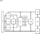
- Fig. 1 shows the block diagram of a preferred embodiment of the device.
- the treatment surface 1 is heated to the treatment temperature with the aid of at least one heating element 2.
- the treatment surface 1 is preferably a contact pad which is made of ceramic or gold.
- semiconductor components such as FETs, very preferably MOSFETs, have proven to be advantageous as heating elements 2. In addition to the small dimensions, they are characterized by very dynamic heat generation and emission and a particularly quick response.
- the temperature of the treatment area 1 is regulated with the aid of a control device 6, which is preferably a microcontroller, and controls the power supply to the heating elements 2.
- the temperature of the treatment area 1 is monitored with the aid of a first temperature sensor 4, which is preferably an NTC thermotransistor.
- the control device 6 can set the optimum power supply in order to keep the treatment temperature constant in the desired period.
- a visual display 7, preferably an LED, and a sound generator 8, preferably a buzzer show the user the phase of the treatment cycle.
- the sound generator 8 can generate a buzzing sound and the visual display 7 can be illuminated.
- the preferred treatment time is entered using the input element 9, which is preferably a button.
- the various program sequences and the regulation of the temperature of the treatment area 1 are controlled by the control device 6.
- the current or voltage supply of the device is provided by a power supply unit 13, for example a battery.
- the hardware-implemented device permits Temperature monitor switches off the heating elements 2 when a maximum temperature is exceeded.
- the device has a second temperature sensor 3, preferably an NTC thermistor, which is connected to a comparator 5. If the temperature of the treatment surface 1 rises, the voltage value at the comparator 5 controlled by the second temperature sensor 3 moves to a reference value of the voltage which corresponds to a predetermined maximum temperature. As soon as the temperature of the treatment surface 1 exceeds the maximum temperature, the output signal at the comparator 5 changes binary, whereby the supply voltage of the heating elements 2 is interrupted.
- the device In addition to the hardware-implemented temperature monitor, the device also has a fuse 11, which functions as an additional fuse element.
- the heating elements 2 draw a defined treatment current from the power supply unit 13 in trouble-free operation. If the heating elements 2 heat up due to a defect, the supply current rises sharply.
- the fuse 11 is advantageously triggered at a maximum current. In this way, an uncontrolled heating of the treatment surface 1 can be avoided even if the device is short-circuited.
- This safety mechanism advantageously only has to intervene if both the temperature regulation by the control device 6 and the hardware-implemented temperature monitor does not function properly.
- the device also includes a voltage supply reverse polarity protection 12 and a voltage monitor 10, which is preferably a supply voltage supervisor (SVS).
- SVS supply voltage supervisor
Claims (14)
- Dispositif de traitement hyperthermique de démangeaisons comprenanta) au moins une surface de traitement (1)
etb) un dispositif de régulation (6) pour la régulation de la température de la surface de traitement (1),dans lequel le dispositif de régulation (6) peut réguler la surface de traitement (1) par chauffage d'au moins un élément chauffant (2) dans une phase de chauffage à une température de traitement entre 42 °C et 56 °C et la température de traitement peut être maintenue dans une phase de traitement pendant une période de 2 s à 12 s,
caractérisé en ce qu'un contrôleur de température implémenté dans le matériel supplémentaire limite la température maximum de la surface de traitement (1) à une valeur entre 54 °C et 58 °C de préférence environ 56 °C de manière réversible et un fusible de sécurité (11) coupe le dispositif en cas de court-circuit ou de chauffage non régulé. - Dispositif selon la revendication précédente
caractérisé en ce que
le dispositif comprend au moins un premier capteur de température (4) pour la mesure de la température de la surface de traitement (1) et le dispositif de régulation (6) règle la température de l'au moins un élément chauffant (2) sur la base des données de mesure du capteur de température (4). - Dispositif selon la revendication précédente
caractérisé en ce que
le contrôleur de température implémenté dans le matériel comprend au moins un deuxième capteur de température (3) pour la mesure de la température de la surface de traitement (1) et un comparateur (5), dans lequel le comparateur (5) compare la température de la surface de traitement (1) avec la température maximum et en cas de dépassement de la température maximum, empêche l'alimentation électrique à l'élément chauffant (2). - Dispositif selon l'une quelconque des revendications précédentes
caractérisé en ce que
le fusible de sécurité (11) présente une valeur seuil pour un courant maximum, lequel correspond au chauffage de la surface de traitement (1) à 65 °C pendant 1 seconde. - Dispositif selon la revendication précédente
caractérisé en ce que
la valeur seuil du fusible de sécurité (11) est de préférence entre 1 A et 2,5 A de manière particulièrement préférée environ 2 A. - Dispositif selon l'une quelconque des revendications précédentes
caractérisé en ce que
la surface de traitement (1) comprend de la céramique et/ou de l'or. - Dispositif selon l'une quelconque des revendications précédentes
caractérisé en ce que
la surface de traitement (1) est bordée par un marquage, lequel est allumé pendant la phase de traitement. - Dispositif selon l'une quelconque des revendications précédentes
caractérisé en ce que
le dispositif comprend un affichage optique (7) et/ou un générateur de son (8), lequel affiche le début de la phase de chauffage, l'atteinte de la température de traitement, la durée de la phase de traitement et/ou la fin de la phase de traitement par un signal acoustique et/ou optique. - Dispositif selon l'une quelconque des revendications précédentes
caractérisé en ce que
le dispositif comprend un boîtier étanche à l'eau. - Dispositif selon l'une quelconque des revendications précédentes
caractérisé en ce que
le dispositif comprend une unité d'alimentation électrique (13) ainsi qu'un contrôleur de tension (10), lequel surveille la tension de l'unité d'alimentation électrique (13). - Dispositif selon l'une quelconque des revendications précédentes
caractérisé en ce que
le dispositif de régulation (6) comprend au moins un microprocesseur. - Dispositif selon la revendication précédente
caractérisé en ce que
le microprocesseur, l'au moins élément chauffant (2) et au moins un capteur de température (3, 4) sont présents installés sur un printed circuit board (PCB), dans lequel au moins l'élément chauffant (2) et le capteur de température (3, 4) sont revêtus à l'aide d'un vernis de protection. - Dispositif selon l'une quelconque des revendications précédentes
caractérisé en ce que
le dispositif comprend une mémoire de données pour la mémorisation de données du système et/ou de messages d'erreur. - Dispositif selon l'une quelconque des revendications précédentes
caractérisé en ce que
un firmware est présent installé sur le dispositif de régulation (6), lequel est lancé lors de la mise en service du dispositif et commande au moins la régulation de température de la surface de traitement (1), dans lequel le dispositif de régulation (6) comprend un Watchdog Counter (WDC) implémenté dans le matériel, lequel surveille si le firmware est exécuté.
Priority Applications (43)
| Application Number | Priority Date | Filing Date | Title |
|---|---|---|---|
| PT161932207T PT3308752T (pt) | 2016-10-11 | 2016-10-11 | Dispositivo para tratamento hipertérmico de prurido |
| ES16193220T ES2800914T3 (es) | 2016-10-11 | 2016-10-11 | Dispositivo para un tratamiento hipertérmico de picores |
| EP16193220.7A EP3308752B1 (fr) | 2016-10-11 | 2016-10-11 | Dispositif de traitement hyperthermique de démangeaisons |
| PL16193220T PL3308752T3 (pl) | 2016-10-11 | 2016-10-11 | Urządzenie do hipertermicznego leczenia świądu |
| HUE16193220A HUE051218T2 (hu) | 2016-10-11 | 2016-10-11 | Készülék viszketés hipertermikus kezelésére |
| LTEP16193220.7T LT3308752T (lt) | 2016-10-11 | 2016-10-11 | Niežėjimo gydymo hiperterminiu būdų prietaisas |
| SI201630821T SI3308752T1 (sl) | 2016-10-11 | 2016-10-11 | Naprava za hipertermično zdravljenje srbečice |
| DK16193220.7T DK3308752T3 (da) | 2016-10-11 | 2016-10-11 | Indretning til hyperthermisk behandling af kløe |
| TW106123228A TWI744353B (zh) | 2016-07-12 | 2017-07-11 | 用於瘙癢症的高熱治療之裝置 |
| TW106123227A TWI772314B (zh) | 2016-07-12 | 2017-07-11 | 用於瘙癢症的高熱治療之裝置 |
| BR112019000498-0A BR112019000498A2 (pt) | 2016-07-12 | 2017-07-12 | dispositivo para tratamento hipertérmico de prurido |
| PCT/EP2017/067542 WO2018011262A1 (fr) | 2016-07-12 | 2017-07-12 | Dispositif pour traiter le prurit par hyperthermie |
| MX2019000405A MX2019000405A (es) | 2016-07-12 | 2017-07-12 | Dispositivo para el tratamiento hipertérmico de prurito. |
| PT177366895T PT3484423T (pt) | 2016-10-11 | 2017-07-12 | Dispositivo para tratamento hipertérmico de prurido |
| EP17736689.5A EP3484423B1 (fr) | 2016-07-12 | 2017-07-12 | Dispositif de traitement hyperthermique de démangeaisons |
| PL17736689T PL3484423T3 (pl) | 2016-07-12 | 2017-07-12 | Urządzenie do hipertermicznego leczenia swędzenia |
| EP17735608.6A EP3484422A1 (fr) | 2016-07-12 | 2017-07-12 | Dispositif pour traiter le prurit par hyperthermie |
| KR1020197004012A KR102485936B1 (ko) | 2016-07-12 | 2017-07-12 | 가려움증의 고열 치료용 장치 |
| JP2019523178A JP2019521825A (ja) | 2016-07-12 | 2017-07-12 | 掻痒症の温熱治療用のデバイス |
| CN201780043034.0A CN109475426A (zh) | 2016-07-12 | 2017-07-12 | 用于对瘙痒进行热疗的设备 |
| AU2017295935A AU2017295935B2 (en) | 2016-07-12 | 2017-07-12 | Device for hyperthermia treatment of itching |
| DK17736689.5T DK3484423T3 (da) | 2016-07-12 | 2017-07-12 | Anordning til hypertermisk behandling af kløe |
| BR112019000502-1A BR112019000502B1 (pt) | 2016-07-12 | 2017-07-12 | Dispositivo para tratamento hipertérmico de coceira |
| EA201892833A EA201892833A1 (ru) | 2016-10-11 | 2017-07-12 | Устройство для гипертермического лечения прурита |
| JP2019523179A JP7129407B2 (ja) | 2016-07-12 | 2017-07-12 | 痒みの温熱治療のためのデバイス |
| AU2017295000A AU2017295000B2 (en) | 2016-07-12 | 2017-07-12 | Device for hyperthermia treatment of pruritus |
| US16/317,147 US11759348B2 (en) | 2016-07-12 | 2017-07-12 | Device for hyperthermia treatment of itching |
| CA3030224A CA3030224A1 (fr) | 2016-07-12 | 2017-07-12 | Dispositif pour traiter le prurit par hyperthermie |
| KR1020197004025A KR102456457B1 (ko) | 2016-07-12 | 2017-07-12 | 가려움증의 고열 치료용 장치 |
| MX2019000408A MX2019000408A (es) | 2016-07-12 | 2017-07-12 | Dispositivo para el tratamiento hipertermico de la picazon. |
| PCT/EP2017/067544 WO2018011263A1 (fr) | 2016-07-12 | 2017-07-12 | Dispositif pour traiter le prurit par hyperthermie |
| US16/317,129 US20190290476A1 (en) | 2016-07-12 | 2017-07-12 | Device for hyperthermia treatment of pruritus |
| HUE17736689A HUE058171T2 (hu) | 2016-07-12 | 2017-07-12 | Eszköz a viszketés hipertermikus kezelésére |
| SG11201900257UA SG11201900257UA (en) | 2016-07-12 | 2017-07-12 | Device for hyperthermia treatment of pruritus |
| EA201892835A EA037168B1 (ru) | 2016-10-11 | 2017-07-12 | Устройство для гипертермического лечения зуда |
| ES17736689T ES2912062T3 (es) | 2016-07-12 | 2017-07-12 | Dispositivo para un tratamiento hipertérmico de picores |
| CN201780043512.8A CN109475427B (zh) | 2016-07-12 | 2017-07-12 | 用于瘙痒的高温治疗的装置 |
| SG11201900258XA SG11201900258XA (en) | 2016-07-12 | 2017-07-12 | Device for hyperthermia treatment of itching |
| CA3030221A CA3030221A1 (fr) | 2016-07-12 | 2017-07-12 | Dispositif pour traiter le prurit par hyperthermie |
| ZA2019/00197A ZA201900197B (en) | 2016-07-12 | 2019-01-11 | Device for hyperthermia treatment of itching |
| CY20201100602T CY1123090T1 (el) | 2016-10-11 | 2020-06-29 | Συσκευη για την υπερθερμικη του κνησμου |
| HRP20201047TT HRP20201047T1 (hr) | 2016-10-11 | 2020-07-02 | Uređaj za hipertermalno liječenje svrbeža |
| JP2022105679A JP2022133362A (ja) | 2016-07-12 | 2022-06-30 | 痒みの温熱治療のためのデバイス |
Applications Claiming Priority (1)
| Application Number | Priority Date | Filing Date | Title |
|---|---|---|---|
| EP16193220.7A EP3308752B1 (fr) | 2016-10-11 | 2016-10-11 | Dispositif de traitement hyperthermique de démangeaisons |
Publications (2)
| Publication Number | Publication Date |
|---|---|
| EP3308752A1 EP3308752A1 (fr) | 2018-04-18 |
| EP3308752B1 true EP3308752B1 (fr) | 2020-04-08 |
Family
ID=57130216
Family Applications (1)
| Application Number | Title | Priority Date | Filing Date |
|---|---|---|---|
| EP16193220.7A Active EP3308752B1 (fr) | 2016-07-12 | 2016-10-11 | Dispositif de traitement hyperthermique de démangeaisons |
Country Status (11)
| Country | Link |
|---|---|
| EP (1) | EP3308752B1 (fr) |
| CY (1) | CY1123090T1 (fr) |
| DK (1) | DK3308752T3 (fr) |
| EA (2) | EA037168B1 (fr) |
| ES (1) | ES2800914T3 (fr) |
| HR (1) | HRP20201047T1 (fr) |
| HU (1) | HUE051218T2 (fr) |
| LT (1) | LT3308752T (fr) |
| PL (1) | PL3308752T3 (fr) |
| PT (2) | PT3308752T (fr) |
| SI (1) | SI3308752T1 (fr) |
Families Citing this family (3)
| Publication number | Priority date | Publication date | Assignee | Title |
|---|---|---|---|---|
| EP3578146A1 (fr) * | 2018-06-07 | 2019-12-11 | Dermapharm AG | Dispositif mobile de traitement de démangeaisons pourvu d'interface |
| TW202023486A (zh) * | 2018-09-05 | 2020-07-01 | 德商得瑪法公司 | 用於治療疱疹疾病之裝置 |
| EP3685810A1 (fr) * | 2019-01-23 | 2020-07-29 | Dermapharm AG | Dispositif mobile de traitement de démangeaisons pourvu d'interface |
Citations (6)
| Publication number | Priority date | Publication date | Assignee | Title |
|---|---|---|---|---|
| EP1231875B1 (fr) | 1999-11-11 | 2004-09-15 | BSM-Bionic Solution Management GmbH | Dispositif de traitement thermique local de piqures et de morsures d'insectes |
| US20060226378A1 (en) | 2003-02-26 | 2006-10-12 | Katsuko Yabiku | Far-infrared generator for thermotherapy and method of far-infrared irradiation |
| US20070049998A1 (en) | 2005-05-18 | 2007-03-01 | Tyrell, Inc. | Treatment device and method for treating skin lesions through application of heat |
| WO2008070580A2 (fr) | 2006-12-04 | 2008-06-12 | Therative, Inc. | Dispositifs et procédés de traitement de problèmes cutanés |
| US8128674B2 (en) | 2006-05-15 | 2012-03-06 | Tearscience, Inc. | System for outer eyelid heat and pressure treatment for treating meibomian gland dysfunction |
| KR20120003394U (ko) | 2010-11-08 | 2012-05-16 | 주식회사 동성웰빙홈 | 휴대용 찜질기 |
Family Cites Families (4)
| Publication number | Priority date | Publication date | Assignee | Title |
|---|---|---|---|---|
| DE102005002946A1 (de) | 2005-01-18 | 2006-07-27 | Bsm - Bionic Solution Management Gmbh | Herpesbehandlungseinrichtung |
| CN103083131B (zh) * | 2007-01-17 | 2015-07-22 | 眼泪科学公司 | 用于治疗睑板腺功能障碍的热处理的方法、系统和装置 |
| WO2011094412A1 (fr) * | 2010-01-27 | 2011-08-04 | Bruder Healthcare Company | Élément chauffant muni d'un fusible thermique |
| US20130172966A1 (en) * | 2010-03-29 | 2013-07-04 | Eliahu ARAD | System for controlling the temperature of a person |
-
2016
- 2016-10-11 LT LTEP16193220.7T patent/LT3308752T/lt unknown
- 2016-10-11 PL PL16193220T patent/PL3308752T3/pl unknown
- 2016-10-11 PT PT161932207T patent/PT3308752T/pt unknown
- 2016-10-11 SI SI201630821T patent/SI3308752T1/sl unknown
- 2016-10-11 ES ES16193220T patent/ES2800914T3/es active Active
- 2016-10-11 EP EP16193220.7A patent/EP3308752B1/fr active Active
- 2016-10-11 HU HUE16193220A patent/HUE051218T2/hu unknown
- 2016-10-11 DK DK16193220.7T patent/DK3308752T3/da active
-
2017
- 2017-07-12 EA EA201892835A patent/EA037168B1/ru unknown
- 2017-07-12 EA EA201892833A patent/EA201892833A1/ru unknown
- 2017-07-12 PT PT177366895T patent/PT3484423T/pt unknown
-
2020
- 2020-06-29 CY CY20201100602T patent/CY1123090T1/el unknown
- 2020-07-02 HR HRP20201047TT patent/HRP20201047T1/hr unknown
Patent Citations (6)
| Publication number | Priority date | Publication date | Assignee | Title |
|---|---|---|---|---|
| EP1231875B1 (fr) | 1999-11-11 | 2004-09-15 | BSM-Bionic Solution Management GmbH | Dispositif de traitement thermique local de piqures et de morsures d'insectes |
| US20060226378A1 (en) | 2003-02-26 | 2006-10-12 | Katsuko Yabiku | Far-infrared generator for thermotherapy and method of far-infrared irradiation |
| US20070049998A1 (en) | 2005-05-18 | 2007-03-01 | Tyrell, Inc. | Treatment device and method for treating skin lesions through application of heat |
| US8128674B2 (en) | 2006-05-15 | 2012-03-06 | Tearscience, Inc. | System for outer eyelid heat and pressure treatment for treating meibomian gland dysfunction |
| WO2008070580A2 (fr) | 2006-12-04 | 2008-06-12 | Therative, Inc. | Dispositifs et procédés de traitement de problèmes cutanés |
| KR20120003394U (ko) | 2010-11-08 | 2012-05-16 | 주식회사 동성웰빙홈 | 휴대용 찜질기 |
Non-Patent Citations (2)
| Title |
|---|
| ANONYM: "Allgemeine Festlegungen für die Sicherheit einschließlich der wesentlichen Leistungsmerkmale (IEC 60601-1:2005)", DEUTSCHE NORM DIN EN 60601-1 (VDE 0750-1) MEDIZINISCHE ELEKTRISCHE GERÄTE, 01-07-2007, pages 1 - 394 |
| DIN DEUTSCHE NORM: "Automatische elektrische Regel- und Steuergeräte für den Hausgebrauch und ähnliche Anwendungen", DEUTSCHE NORM ENTWURF DIN IEC 60730-2-9, 1 November 2003 (2003-11-01), pages 1 - 17, XP055806464 |
Also Published As
| Publication number | Publication date |
|---|---|
| EA037168B1 (ru) | 2021-02-15 |
| EA201892835A1 (ru) | 2019-10-31 |
| EP3308752A1 (fr) | 2018-04-18 |
| EA201892833A1 (ru) | 2019-08-30 |
| ES2800914T3 (es) | 2021-01-05 |
| HUE051218T2 (hu) | 2021-03-01 |
| PL3308752T3 (pl) | 2020-09-21 |
| SI3308752T1 (sl) | 2020-08-31 |
| PT3484423T (pt) | 2022-04-04 |
| PT3308752T (pt) | 2020-07-10 |
| HRP20201047T1 (hr) | 2020-10-16 |
| CY1123090T1 (el) | 2021-10-29 |
| DK3308752T3 (da) | 2020-06-22 |
| LT3308752T (lt) | 2020-07-27 |
Similar Documents
| Publication | Publication Date | Title |
|---|---|---|
| EP3484423B1 (fr) | Dispositif de traitement hyperthermique de démangeaisons | |
| EP3308752B1 (fr) | Dispositif de traitement hyperthermique de démangeaisons | |
| EP3846753B1 (fr) | Dispositif de traitement des infections liées au prurit et à l'éruption herpitiforme à l'aide d'un capteur de contact | |
| EP1971301A1 (fr) | Appareil manuel et procede de traitement thermique d'un emplacement affecte par une piqure ou une morsure d'insecte | |
| EP1231875A1 (fr) | Dispositif de traitement thermique local de piqures et de morsures d'insectes | |
| WO2019020144A1 (fr) | Dispositif portatif à couplage pour le traitement médical thermique de la peau | |
| DE202016008836U1 (de) | Vorrichtung zur hyperthermischen Behandlung von Juckreiz | |
| DE202018105061U1 (de) | Vorrichtung zur Herpesbehandlung durch Wärmeanwendung | |
| EP3620141A1 (fr) | Dispositif de traitement des infections liées au prurit et à l'éruption herpitiforme à l'aide d'un capteur de contact | |
| WO2019234172A1 (fr) | Dispositif mobile à interface pour le traitement d'un prurit | |
| EP3620142A1 (fr) | Dispositif de traitement des infections liées à l'éruption herpitiforme | |
| WO2020152239A1 (fr) | Dispositif mobile à interface pour le traitement d'un prurit | |
| DE102019103291B4 (de) | Verfahren zum Betreiben eines Heizsystems eines Endoskops, Heizsystem eines Endoskops und Endoskopsystem | |
| EA040683B1 (ru) | Устройство для гипертермического лечения прурита | |
| DE202021104538U1 (de) | System für UV-Bestrahlung und UV-Therapie |
Legal Events
| Date | Code | Title | Description |
|---|---|---|---|
| REG | Reference to a national code |
Ref country code: DE Ref legal event code: R138 Ref document number: 202016008836 Country of ref document: DE Free format text: GERMAN DOCUMENT NUMBER IS 502016009449 |
|
| PUAI | Public reference made under article 153(3) epc to a published international application that has entered the european phase |
Free format text: ORIGINAL CODE: 0009012 |
|
| STAA | Information on the status of an ep patent application or granted ep patent |
Free format text: STATUS: THE APPLICATION HAS BEEN PUBLISHED |
|
| AK | Designated contracting states |
Kind code of ref document: A1 Designated state(s): AL AT BE BG CH CY CZ DE DK EE ES FI FR GB GR HR HU IE IS IT LI LT LU LV MC MK MT NL NO PL PT RO RS SE SI SK SM TR |
|
| AX | Request for extension of the european patent |
Extension state: BA ME |
|
| STAA | Information on the status of an ep patent application or granted ep patent |
Free format text: STATUS: REQUEST FOR EXAMINATION WAS MADE |
|
| 17P | Request for examination filed |
Effective date: 20181016 |
|
| RBV | Designated contracting states (corrected) |
Designated state(s): AL AT BE BG CH CY CZ DE DK EE ES FI FR GB GR HR HU IE IS IT LI LT LU LV MC MK MT NL NO PL PT RO RS SE SI SK SM TR |
|
| REG | Reference to a national code |
Ref country code: HK Ref legal event code: DE Ref document number: 1250906 Country of ref document: HK |
|
| GRAP | Despatch of communication of intention to grant a patent |
Free format text: ORIGINAL CODE: EPIDOSNIGR1 |
|
| STAA | Information on the status of an ep patent application or granted ep patent |
Free format text: STATUS: GRANT OF PATENT IS INTENDED |
|
| GRAS | Grant fee paid |
Free format text: ORIGINAL CODE: EPIDOSNIGR3 |
|
| GRAJ | Information related to disapproval of communication of intention to grant by the applicant or resumption of examination proceedings by the epo deleted |
Free format text: ORIGINAL CODE: EPIDOSDIGR1 |
|
| GRAL | Information related to payment of fee for publishing/printing deleted |
Free format text: ORIGINAL CODE: EPIDOSDIGR3 |
|
| STAA | Information on the status of an ep patent application or granted ep patent |
Free format text: STATUS: REQUEST FOR EXAMINATION WAS MADE |
|
| GRAR | Information related to intention to grant a patent recorded |
Free format text: ORIGINAL CODE: EPIDOSNIGR71 |
|
| INTG | Intention to grant announced |
Effective date: 20200204 |
|
| STAA | Information on the status of an ep patent application or granted ep patent |
Free format text: STATUS: GRANT OF PATENT IS INTENDED |
|
| GRAA | (expected) grant |
Free format text: ORIGINAL CODE: 0009210 |
|
| STAA | Information on the status of an ep patent application or granted ep patent |
Free format text: STATUS: THE PATENT HAS BEEN GRANTED |
|
| INTC | Intention to grant announced (deleted) | ||
| AK | Designated contracting states |
Kind code of ref document: B1 Designated state(s): AL AT BE BG CH CY CZ DE DK EE ES FI FR GB GR HR HU IE IS IT LI LT LU LV MC MK MT NL NO PL PT RO RS SE SI SK SM TR |
|
| INTG | Intention to grant announced |
Effective date: 20200304 |
|
| REG | Reference to a national code |
Ref country code: CH Ref legal event code: EP Ref country code: AT Ref legal event code: REF Ref document number: 1253344 Country of ref document: AT Kind code of ref document: T Effective date: 20200415 |
|
| REG | Reference to a national code |
Ref country code: DE Ref legal event code: R096 Ref document number: 502016009449 Country of ref document: DE |
|
| REG | Reference to a national code |
Ref country code: IE Ref legal event code: FG4D Free format text: LANGUAGE OF EP DOCUMENT: GERMAN |
|
| REG | Reference to a national code |
Ref country code: DK Ref legal event code: T3 Effective date: 20200618 |
|
| REG | Reference to a national code |
Ref country code: HR Ref legal event code: TUEP Ref document number: P20201047 Country of ref document: HR |
|
| REG | Reference to a national code |
Ref country code: FI Ref legal event code: FGE |
|
| REG | Reference to a national code |
Ref country code: PT Ref legal event code: SC4A Ref document number: 3308752 Country of ref document: PT Date of ref document: 20200710 Kind code of ref document: T Free format text: AVAILABILITY OF NATIONAL TRANSLATION Effective date: 20200703 |
|
| REG | Reference to a national code |
Ref country code: NO Ref legal event code: T2 Effective date: 20200408 |
|
| REG | Reference to a national code |
Ref country code: SE Ref legal event code: TRGR |
|
| REG | Reference to a national code |
Ref country code: NL Ref legal event code: FP |
|
| REG | Reference to a national code |
Ref country code: EE Ref legal event code: FG4A Ref document number: E019405 Country of ref document: EE Effective date: 20200702 |
|
| REG | Reference to a national code |
Ref country code: GR Ref legal event code: EP Ref document number: 20200401809 Country of ref document: GR Effective date: 20200916 |
|
| REG | Reference to a national code |
Ref country code: SK Ref legal event code: T3 Ref document number: E 34712 Country of ref document: SK |
|
| REG | Reference to a national code |
Ref country code: HR Ref legal event code: T1PR Ref document number: P20201047 Country of ref document: HR |
|
| PG25 | Lapsed in a contracting state [announced via postgrant information from national office to epo] |
Ref country code: IS Free format text: LAPSE BECAUSE OF FAILURE TO SUBMIT A TRANSLATION OF THE DESCRIPTION OR TO PAY THE FEE WITHIN THE PRESCRIBED TIME-LIMIT Effective date: 20200808 |
|
| REG | Reference to a national code |
Ref country code: HR Ref legal event code: ODRP Ref document number: P20201047 Country of ref document: HR Payment date: 20201006 Year of fee payment: 5 |
|
| PG25 | Lapsed in a contracting state [announced via postgrant information from national office to epo] |
Ref country code: RS Free format text: LAPSE BECAUSE OF FAILURE TO SUBMIT A TRANSLATION OF THE DESCRIPTION OR TO PAY THE FEE WITHIN THE PRESCRIBED TIME-LIMIT Effective date: 20200408 Ref country code: BG Free format text: LAPSE BECAUSE OF FAILURE TO SUBMIT A TRANSLATION OF THE DESCRIPTION OR TO PAY THE FEE WITHIN THE PRESCRIBED TIME-LIMIT Effective date: 20200708 |
|
| PG25 | Lapsed in a contracting state [announced via postgrant information from national office to epo] |
Ref country code: AL Free format text: LAPSE BECAUSE OF FAILURE TO SUBMIT A TRANSLATION OF THE DESCRIPTION OR TO PAY THE FEE WITHIN THE PRESCRIBED TIME-LIMIT Effective date: 20200408 |
|
| REG | Reference to a national code |
Ref country code: ES Ref legal event code: FG2A Ref document number: 2800914 Country of ref document: ES Kind code of ref document: T3 Effective date: 20210105 |
|
| REG | Reference to a national code |
Ref country code: DE Ref legal event code: R026 Ref document number: 502016009449 Country of ref document: DE |
|
| PLBI | Opposition filed |
Free format text: ORIGINAL CODE: 0009260 |
|
| PLAX | Notice of opposition and request to file observation + time limit sent |
Free format text: ORIGINAL CODE: EPIDOSNOBS2 |
|
| PG25 | Lapsed in a contracting state [announced via postgrant information from national office to epo] |
Ref country code: SM Free format text: LAPSE BECAUSE OF FAILURE TO SUBMIT A TRANSLATION OF THE DESCRIPTION OR TO PAY THE FEE WITHIN THE PRESCRIBED TIME-LIMIT Effective date: 20200408 |
|
| REG | Reference to a national code |
Ref country code: FI Ref legal event code: MDE Opponent name: KAMEDI GMBH |
|
| 26 | Opposition filed |
Opponent name: KAMEDI GMBH Effective date: 20210107 |
|
| REG | Reference to a national code |
Ref country code: HU Ref legal event code: AG4A Ref document number: E051218 Country of ref document: HU |
|
| PLBB | Reply of patent proprietor to notice(s) of opposition received |
Free format text: ORIGINAL CODE: EPIDOSNOBS3 |
|
| PG25 | Lapsed in a contracting state [announced via postgrant information from national office to epo] |
Ref country code: LU Free format text: LAPSE BECAUSE OF NON-PAYMENT OF DUE FEES Effective date: 20201011 Ref country code: MC Free format text: LAPSE BECAUSE OF FAILURE TO SUBMIT A TRANSLATION OF THE DESCRIPTION OR TO PAY THE FEE WITHIN THE PRESCRIBED TIME-LIMIT Effective date: 20200408 |
|
| REG | Reference to a national code |
Ref country code: HR Ref legal event code: ODRP Ref document number: P20201047 Country of ref document: HR Payment date: 20211103 Year of fee payment: 6 |
|
| PGFP | Annual fee paid to national office [announced via postgrant information from national office to epo] |
Ref country code: CZ Payment date: 20211102 Year of fee payment: 6 Ref country code: HR Payment date: 20211103 Year of fee payment: 6 Ref country code: LT Payment date: 20211028 Year of fee payment: 6 Ref country code: IE Payment date: 20211021 Year of fee payment: 6 Ref country code: FI Payment date: 20211019 Year of fee payment: 6 Ref country code: EE Payment date: 20211020 Year of fee payment: 6 Ref country code: RO Payment date: 20211103 Year of fee payment: 6 Ref country code: SK Payment date: 20211103 Year of fee payment: 6 Ref country code: NO Payment date: 20211020 Year of fee payment: 6 |
|
| PGFP | Annual fee paid to national office [announced via postgrant information from national office to epo] |
Ref country code: SI Payment date: 20211102 Year of fee payment: 6 Ref country code: LV Payment date: 20211019 Year of fee payment: 6 Ref country code: HU Payment date: 20211030 Year of fee payment: 6 Ref country code: GR Payment date: 20211020 Year of fee payment: 6 |
|
| PG25 | Lapsed in a contracting state [announced via postgrant information from national office to epo] |
Ref country code: MT Free format text: LAPSE BECAUSE OF FAILURE TO SUBMIT A TRANSLATION OF THE DESCRIPTION OR TO PAY THE FEE WITHIN THE PRESCRIBED TIME-LIMIT Effective date: 20200408 |
|
| PGFP | Annual fee paid to national office [announced via postgrant information from national office to epo] |
Ref country code: CY Payment date: 20211029 Year of fee payment: 6 |
|
| PLBP | Opposition withdrawn |
Free format text: ORIGINAL CODE: 0009264 |
|
| PG25 | Lapsed in a contracting state [announced via postgrant information from national office to epo] |
Ref country code: MK Free format text: LAPSE BECAUSE OF FAILURE TO SUBMIT A TRANSLATION OF THE DESCRIPTION OR TO PAY THE FEE WITHIN THE PRESCRIBED TIME-LIMIT Effective date: 20200408 |
|
| REG | Reference to a national code |
Ref country code: HR Ref legal event code: PBON Ref document number: P20201047 Country of ref document: HR Effective date: 20221011 |
|
| PG25 | Lapsed in a contracting state [announced via postgrant information from national office to epo] |
Ref country code: CZ Free format text: LAPSE BECAUSE OF NON-PAYMENT OF DUE FEES Effective date: 20221011 |
|
| REG | Reference to a national code |
Ref country code: LT Ref legal event code: MM4D Effective date: 20221011 |
|
| REG | Reference to a national code |
Ref country code: EE Ref legal event code: MM4A Ref document number: E019405 Country of ref document: EE Effective date: 20221031 |
|
| REG | Reference to a national code |
Ref country code: NO Ref legal event code: MMEP |
|
| REG | Reference to a national code |
Ref country code: SK Ref legal event code: MM4A Ref document number: E 34712 Country of ref document: SK Effective date: 20221011 |
|
| P01 | Opt-out of the competence of the unified patent court (upc) registered |
Effective date: 20230509 |
|
| PG25 | Lapsed in a contracting state [announced via postgrant information from national office to epo] |
Ref country code: RO Free format text: LAPSE BECAUSE OF NON-PAYMENT OF DUE FEES Effective date: 20221011 Ref country code: NO Free format text: LAPSE BECAUSE OF NON-PAYMENT OF DUE FEES Effective date: 20221031 Ref country code: LV Free format text: LAPSE BECAUSE OF NON-PAYMENT OF DUE FEES Effective date: 20221011 Ref country code: LT Free format text: LAPSE BECAUSE OF NON-PAYMENT OF DUE FEES Effective date: 20221011 Ref country code: HU Free format text: LAPSE BECAUSE OF NON-PAYMENT OF DUE FEES Effective date: 20221012 Ref country code: HR Free format text: LAPSE BECAUSE OF NON-PAYMENT OF DUE FEES Effective date: 20221011 Ref country code: EE Free format text: LAPSE BECAUSE OF NON-PAYMENT OF DUE FEES Effective date: 20221031 Ref country code: CY Free format text: LAPSE BECAUSE OF NON-PAYMENT OF DUE FEES Effective date: 20221011 |
|
| REG | Reference to a national code |
Ref country code: SI Ref legal event code: KO00 Effective date: 20230629 |
|
| PG25 | Lapsed in a contracting state [announced via postgrant information from national office to epo] |
Ref country code: SK Free format text: LAPSE BECAUSE OF NON-PAYMENT OF DUE FEES Effective date: 20221011 Ref country code: SI Free format text: LAPSE BECAUSE OF NON-PAYMENT OF DUE FEES Effective date: 20221012 Ref country code: GR Free format text: LAPSE BECAUSE OF NON-PAYMENT OF DUE FEES Effective date: 20230508 |
|
| PG25 | Lapsed in a contracting state [announced via postgrant information from national office to epo] |
Ref country code: IE Free format text: LAPSE BECAUSE OF NON-PAYMENT OF DUE FEES Effective date: 20221011 |
|
| PGFP | Annual fee paid to national office [announced via postgrant information from national office to epo] |
Ref country code: PT Payment date: 20230928 Year of fee payment: 8 Ref country code: PL Payment date: 20230928 Year of fee payment: 8 Ref country code: NL Payment date: 20231023 Year of fee payment: 8 |
|
| PGFP | Annual fee paid to national office [announced via postgrant information from national office to epo] |
Ref country code: GB Payment date: 20231025 Year of fee payment: 8 |
|
| PGFP | Annual fee paid to national office [announced via postgrant information from national office to epo] |
Ref country code: ES Payment date: 20231117 Year of fee payment: 8 |
|
| PGFP | Annual fee paid to national office [announced via postgrant information from national office to epo] |
Ref country code: TR Payment date: 20231003 Year of fee payment: 8 Ref country code: SE Payment date: 20231025 Year of fee payment: 8 Ref country code: IT Payment date: 20231031 Year of fee payment: 8 Ref country code: FR Payment date: 20231023 Year of fee payment: 8 Ref country code: DK Payment date: 20231025 Year of fee payment: 8 Ref country code: DE Payment date: 20230926 Year of fee payment: 8 Ref country code: CH Payment date: 20231102 Year of fee payment: 8 Ref country code: AT Payment date: 20231019 Year of fee payment: 8 |
|
| PGFP | Annual fee paid to national office [announced via postgrant information from national office to epo] |
Ref country code: BE Payment date: 20231023 Year of fee payment: 8 |
|
| PLBD | Termination of opposition procedure: decision despatched |
Free format text: ORIGINAL CODE: EPIDOSNOPC1 |
|
| PG25 | Lapsed in a contracting state [announced via postgrant information from national office to epo] |
Ref country code: FI Free format text: LAPSE BECAUSE OF NON-PAYMENT OF DUE FEES Effective date: 20221011 |