EP3308698B1 - Sonde und verfahren zum betrieb einer sonde - Google Patents
Sonde und verfahren zum betrieb einer sonde Download PDFInfo
- Publication number
- EP3308698B1 EP3308698B1 EP16306359.7A EP16306359A EP3308698B1 EP 3308698 B1 EP3308698 B1 EP 3308698B1 EP 16306359 A EP16306359 A EP 16306359A EP 3308698 B1 EP3308698 B1 EP 3308698B1
- Authority
- EP
- European Patent Office
- Prior art keywords
- probe
- dipole moment
- permanent magnetic
- magnetic dipole
- energy
- Prior art date
- Legal status (The legal status is an assumption and is not a legal conclusion. Google has not performed a legal analysis and makes no representation as to the accuracy of the status listed.)
- Active
Links
Images


Classifications
-
- A—HUMAN NECESSITIES
- A61—MEDICAL OR VETERINARY SCIENCE; HYGIENE
- A61B—DIAGNOSIS; SURGERY; IDENTIFICATION
- A61B5/00—Measuring for diagnostic purposes; Identification of persons
- A61B5/0002—Remote monitoring of patients using telemetry, e.g. transmission of vital signals via a communication network
- A61B5/0031—Implanted circuitry
-
- A—HUMAN NECESSITIES
- A61—MEDICAL OR VETERINARY SCIENCE; HYGIENE
- A61B—DIAGNOSIS; SURGERY; IDENTIFICATION
- A61B5/00—Measuring for diagnostic purposes; Identification of persons
- A61B5/07—Endoradiosondes
-
- A—HUMAN NECESSITIES
- A61—MEDICAL OR VETERINARY SCIENCE; HYGIENE
- A61B—DIAGNOSIS; SURGERY; IDENTIFICATION
- A61B5/00—Measuring for diagnostic purposes; Identification of persons
- A61B5/68—Arrangements of detecting, measuring or recording means, e.g. sensors, in relation to patient
- A61B5/6846—Arrangements of detecting, measuring or recording means, e.g. sensors, in relation to patient specially adapted to be brought in contact with an internal body part, i.e. invasive
- A61B5/6847—Arrangements of detecting, measuring or recording means, e.g. sensors, in relation to patient specially adapted to be brought in contact with an internal body part, i.e. invasive mounted on an invasive device
- A61B5/6861—Capsules, e.g. for swallowing or implanting
-
- A—HUMAN NECESSITIES
- A61—MEDICAL OR VETERINARY SCIENCE; HYGIENE
- A61N—ELECTROTHERAPY; MAGNETOTHERAPY; RADIATION THERAPY; ULTRASOUND THERAPY
- A61N1/00—Electrotherapy; Circuits therefor
- A61N1/18—Applying electric currents by contact electrodes
- A61N1/32—Applying electric currents by contact electrodes alternating or intermittent currents
- A61N1/36—Applying electric currents by contact electrodes alternating or intermittent currents for stimulation
- A61N1/372—Arrangements in connection with the implantation of stimulators
- A61N1/378—Electrical supply
- A61N1/3787—Electrical supply from an external energy source
-
- H—ELECTRICITY
- H02—GENERATION; CONVERSION OR DISTRIBUTION OF ELECTRIC POWER
- H02J—ELECTRIC POWER NETWORKS; CIRCUIT ARRANGEMENTS OR SYSTEMS FOR SUPPLYING OR DISTRIBUTING ELECTRIC POWER; SYSTEMS FOR STORING ELECTRIC ENERGY
- H02J50/00—Circuit arrangements or systems for wireless supply or distribution of electric power
- H02J50/10—Circuit arrangements or systems for wireless supply or distribution of electric power using inductive coupling
-
- H—ELECTRICITY
- H02—GENERATION; CONVERSION OR DISTRIBUTION OF ELECTRIC POWER
- H02J—ELECTRIC POWER NETWORKS; CIRCUIT ARRANGEMENTS OR SYSTEMS FOR SUPPLYING OR DISTRIBUTING ELECTRIC POWER; SYSTEMS FOR STORING ELECTRIC ENERGY
- H02J50/00—Circuit arrangements or systems for wireless supply or distribution of electric power
- H02J50/90—Circuit arrangements or systems for wireless supply or distribution of electric power involving detection or optimisation of position, e.g. alignment
-
- A—HUMAN NECESSITIES
- A61—MEDICAL OR VETERINARY SCIENCE; HYGIENE
- A61B—DIAGNOSIS; SURGERY; IDENTIFICATION
- A61B2560/00—Constructional details of operational features of apparatus; Accessories for medical measuring apparatus
- A61B2560/02—Operational features
- A61B2560/0204—Operational features of power management
- A61B2560/0214—Operational features of power management of power generation or supply
- A61B2560/0219—Operational features of power management of power generation or supply of externally powered implanted units
-
- H—ELECTRICITY
- H01—ELECTRIC ELEMENTS
- H01F—MAGNETS; INDUCTANCES; TRANSFORMERS; SELECTION OF MATERIALS FOR THEIR MAGNETIC PROPERTIES
- H01F3/00—Cores, Yokes, or armatures
- H01F3/10—Composite arrangements of magnetic circuits
- H01F2003/103—Magnetic circuits with permanent magnets
-
- H—ELECTRICITY
- H02—GENERATION; CONVERSION OR DISTRIBUTION OF ELECTRIC POWER
- H02J—ELECTRIC POWER NETWORKS; CIRCUIT ARRANGEMENTS OR SYSTEMS FOR SUPPLYING OR DISTRIBUTING ELECTRIC POWER; SYSTEMS FOR STORING ELECTRIC ENERGY
- H02J2105/00—Networks for supplying or distributing electric power characterised by their spatial reach or by the load
- H02J2105/40—Networks for supplying or distributing electric power characterised by their spatial reach or by the load characterised by the loads connecting to the networks or being supplied by the networks
- H02J2105/46—Medical devices, medical implants or life supporting devices
-
- H—ELECTRICITY
- H04—ELECTRIC COMMUNICATION TECHNIQUE
- H04B—TRANSMISSION
- H04B5/00—Near-field transmission systems, e.g. inductive or capacitive transmission systems
- H04B5/20—Near-field transmission systems, e.g. inductive or capacitive transmission systems characterised by the transmission technique; characterised by the transmission medium
- H04B5/24—Inductive coupling
-
- H—ELECTRICITY
- H04—ELECTRIC COMMUNICATION TECHNIQUE
- H04B—TRANSMISSION
- H04B5/00—Near-field transmission systems, e.g. inductive or capacitive transmission systems
- H04B5/70—Near-field transmission systems, e.g. inductive or capacitive transmission systems specially adapted for specific purposes
- H04B5/79—Near-field transmission systems, e.g. inductive or capacitive transmission systems specially adapted for specific purposes for data transfer in combination with power transfer
Definitions
- the disclosure relates to a probe for use in the human and/or animal body.
- the disclosure further relates to a method of operating such a probe and to a system comprising at least one probe of the aforementioned type.
- probe means a device that may be placed in the body of a human or animal.
- Conventional probes may e.g. be introduced into a human or animal body, e.g. into the gastro-intestinal (GI) tract of the human or the animal to measure certain physical parameters in the animal or human body.
- the conventional probes typically use radio frequency, RF, signals for communication with a device external to the body, and such RF communication may require comparatively large antennas for transmitting the RF signals.
- the conventional probes are battery-powered, i.e. comprising a comparatively large installation space for the battery, while having a rather limited operating time. These factors prevent further miniaturization of the conventional probes and limit the usability to few fields of application.
- US 2011/0304220 A1 discloses an inductive power transfer apparatus for a non-contact movement of at least one magnetic body.
- the body is arranged in a primary magnetic field of a permanent magnet which moves in a defined manner. Further a magnetic field sensor is provided to record a secondary magnetic field of the magnetic body.
- WO 2016/010772 A1 refers to wireless power transfer using a transmitter that generates a dynamic magnetic field and receiver comprising a magnet and coil.
- the magnet rotates in response to the dynamic magnetic field and induces a voltage across the coil.
- the probe comprises a housing, at least one element having a permanent magnetic dipole moment, and an electrical circuit, the element having a permanent magnetic dipole moment being rotatable within said housing, the element having a permanent magnetic dipole moment being configured to generate an electromotive force in said electrical circuit in response to being rotated.
- This configuration advantageously enables to supply the probe with energy from an external source, e.g. by driving a rotating movement of the element having a permanent magnetic dipole moment using magnetic fields generated and/or controlled by said external source.
- an external source e.g. by driving a rotating movement of the element having a permanent magnetic dipole moment using magnetic fields generated and/or controlled by said external source.
- exchange of information between the probe or a component thereof and an external device is enabled, as will be explained in detail further below.
- the probe does not necessarily require a local storage medium for electric energy such as a battery or the like, as energy may be provided from the external source just in time, e.g. when required.
- the magnetic fields generated and/or controlled by said external source are not substantially attenuated by the human or animal body so that an efficient energy transfer (and also communication) is enabled between the external source and the probe even if the probe is positioned within body tissue.
- the probe is particularly well-suited for use in the human or animal body, according to further embodiments, it may also be used in other environments such as e.g. (biochemical) reactors, pipes, or generally any other target systems where measurements are to be made and/or where agents are to be deployed, especially if a direct mechanical contact to said probe is at least temporarily impossible.
- the principle according to the embodiments relies on magnetic fields to drive the rotatable element having a permanent magnetic dipole moment of the probe, energy transfer from an external device to said probe is nearly always possible, except with situations where a strong magnetic shielding is applied around the probe.
- the electric circuit comprises at least one induction coil, as will be explained in further detail below.
- the electrical circuit may comprise one or more electronic components such as e.g. a control unit, as will also be explained in further detail below.
- the element having a permanent magnetic dipole moment is rotatably attached to a shaft, wherein said shaft is e.g. fixedly attached to an inner wall of said housing of the probe or a suitable mechanical support structure provided within said housing.
- an external bearing may be provided for rotatably arranging said element having a permanent magnetic dipole moment within said housing of the probe.
- said element having a permanent magnetic dipole moment comprises at least one permanent magnet, wherein preferably a maximum length dimension of said permanent magnet is smaller than about 15 millimeter (mm), more preferably smaller than about 1.5 mm, which enables a particularly small configuration.
- said element having a permanent magnetic dipole moment or permanent magnet may comprise or consist of a bar magnet, wherein said bar magnet may substantially comprise cuboid shape with a width a, a length b, and a depth c, wherein e.g. b > a and b > c, and wherein said length b e.g. corresponds to the abovementioned maximum length dimension, wherein preferably b ⁇ 15 mm, or more preferably b ⁇ 1.5mm.
- These dimensions enable a very compact structure for the complete probe, so that efficient deployment e.g. in blood vessels and other regions of the human and/or animal body is possible, e.g. by injecting the probe to the target region.
- magnetic material of the NdFeB-type i.e. comprising an alloy of neodymium (Nd), iron (Fe) and boron (B), e.g. Nd2Fe14B, may be used to form the element having a permanent magnetic dipole moment or components thereof.
- the abovementioned bar magnet which may be considered as a simple exemplary embodiment of a magnetic dipole, is particularly preferred due to its simplicity and commercial availability.
- other types of elements with non-vanishing magnetic dipole moments may also be used within the probe.
- said probe comprises an induction coil that is magnetically coupled with said element having a permanent magnetic dipole moment so that an electromotive force is produced in said induction coil by rotation of said element having a permanent magnetic dipole moment.
- a controllable electric resistor is connected in parallel with (i.e., "across") said induction coil.
- An external magnetic "receiver” may monitor the magnetic field caused by the rotating element having a permanent magnetic dipole moment, whereby e.g. an amplitude and/or a frequency of an electric voltage induced into a receiver coil of the magnetic "receiver" may be determined.
- Variations in amplitude and/or frequency of said induced voltage may in a per se known manner be caused by extracting energy using the internal induction coil of the probe according to the present embodiment, such that by modulating the controllable resistor of the internal induction coil an externally detectable signal may be provided, which may be used for data communication between the probe and an external device connected to said external receiver coil.
- a transfer of information from an external device to the probe may be effected by controlling or varying the frequency and/or amplitude of the externally applied magnetic field.
- the magnetic coupling between the induction coil and the element having a permanent magnetic dipole moment of the probe means that said induction coil is configured and arranged relatively to said element having a permanent magnetic dipole moment such that at least a part of the magnetic flux of the element having a permanent magnetic dipole moment may at least temporarily (e.g., depending on an angular position of the rotatably arranged element having a permanent magnetic dipole moment) pass through said induction coil.
- a control unit is provided in said housing, i.e. local to said probe.
- Said control unit may e.g. control an operation of the probe, for example by determining (e.g., by measuring) at least one of: a frequency and/or amplitude of an external magnetic field, a rotational speed of the element having a permanent magnetic dipole moment of the probe.
- the control unit may e.g. comprise an ASIC (application specific integrated circuit), a microcontroller, a digital signal processor (DSP), discrete logic elements, a programmable logic circuit or any combination thereof.
- ASIC application specific integrated circuit
- DSP digital signal processor
- the probe may comprise one or more sensors, which may preferably at least partly be integrated into the housing of the probe, and which may be configured to measure one or more physical parameters of the probe and/or a medium surrounding the probe (i.e., temperature, pressure, pH value).
- an optional control unit may evaluate sensor signals provided by said sensors.
- the sensor signals or any data derived therefrom may be transmitted to an external device, e.g. by modulating the controllable electric resistor and thus an angular speed of the element having a permanent magnetic dipole moment as mentioned above.
- said housing has a basically ellipsoidal or spherical shape, which facilitates movement or transport, respectively, of said probe in the target system (e.g. a gastrointestinal tract or a blood vessel or the like of a human being or an animal).
- the target system e.g. a gastrointestinal tract or a blood vessel or the like of a human being or an animal.
- polygonal or cuboid shapes may also be provided for the housing, especially in cases where it is preferred that the probe retains its position within the target system.
- said probe comprises a device for: transforming mechanical rotational energy of said element having a permanent magnetic dipole moment into electrical energy, and/or into thermal energy, and/or into a flow of a fluid surrounding the housing of said probe and/or within the housing of said probe, and/or into propulsion energy for moving said probe.
- the device for transforming mechanical rotational energy of said element having a permanent magnetic dipole moment into electrical energy may e.g. comprise an induction coil arranged locally in said probe, which induction coil is magnetically coupled to said element having a permanent magnetic dipole moment, similar to the embodiment with the induction coil and controllable resistor in parallel as explained above.
- said device for transforming mechanical rotation energy into electrical energy may comprise an electric generator which is directly mechanically driven by the rotating element having a permanent magnetic dipole moment.
- a shaft of the electric generator may be driven by the rotating element having a permanent magnetic dipole moment or a shaft of the rotating element having a permanent magnetic dipole moment.
- said device for transforming mechanical rotational energy of said element having a permanent magnetic dipole moment into thermal energy may comprise a friction mechanism, wherein friction effects between the rotating element having a permanent magnetic dipole moment and at least one friction element contactable by the element having a permanent magnetic dipole moment cause transformation of rotational energy of the element having a permanent magnetic dipole moment into thermal energy.
- the element having a permanent magnetic dipole moment may comprise a mass imbalance with respect to its axis of rotation so that a portion of its rotational energy may be transformed into vibrations, e.g. structure-borne noise.
- the device for transforming mechanical rotational energy of said element having a permanent magnetic dipole moment into a flow of a fluid surrounding the housing of said probe and/or within the housing of said probe may comprise a propelling screw or the like effecting movement of a fluid outside of or inside of the probe.
- a shaft of said element having a permanent magnetic dipole moment may be coupled to a propelling screw arranged at least partially outside of the housing of the probe.
- the probe may comprise at least one fluid channel which is in fluid communication with a fluid surrounding the probe, and in said fluid channel a propelling screw driven by the element having a permanent magnetic dipole moment may be provided.
- said probe is configured to carry at least one agent, preferably a drug to be released within the human and/or animal body, and said probe is further configured to controllably release said agent, e.g. under control of a local control unit and/or under control of an external device transmitting corresponding control commands to the probe.
- Some embodiments feature a method of operating a probe for use in the human and/or animal body according to claim 8.
- said probe comprises an induction coil that is magnetically coupled with said element having a permanent magnetic dipole moment, wherein said probe applies a predetermined magnetic damping to the element having a permanent magnetic dipole moment by controlling a resistance of a controllable electric resistor connected in parallel with said induction coil.
- the application of said predetermined magnetic damping to the element having a permanent magnetic dipole moment is used for transmitting data from the probe to an external device.
- said probe transforms mechanical rotation energy obtained from said element having a permanent magnetic dipole moment into at least one of: a) electrical energy, b) thermal energy, c) a flow of a fluid surrounding the housing of said probe and/or within the housing of said probe, d) propulsion energy for moving said probe, e) acoustic, preferably ultrasonic, energy.
- Yet further examples feature a system comprising at least one probe according to the embodiments and a magnetic field generator configured to provide a magnetic field in said at least one probe.
- said magnetic field generator may comprise at lease on pair of Helmholtz coils which may be arranged external to and preferably surrounding said at least one probe, providing a basically homogenous magnetic field between said pair of Helmholtz coils.
- said magnetic field generator is configured to provide a substantially static magnetic field to align the element having a permanent magnetic dipole moment in a selected direction.
- said magnetic field generator is configured to, in a first operational state, provide a temporally alternating magnetic field, particularly to drive a rotational movement of the element having a permanent magnetic dipole moment of said at least one probe, wherein optionally, said magnetic field generator is configured to, in a second operational state, provide a substantially static magnetic field, particularly to align the element having a permanent magnetic dipole moment of said at least one probe in a predetermined direction depending on said substantially static magnetic field.
- the first operational state may be employed to supply the probe with mechanical energy
- the second operational state may be used to align the element having a permanent magnetic dipole moment with the magnetic field provided in said second operational state, e.g. to establish a defined (optimum) starting position prior to entering the first operational mode.
- said system comprises a receiver configured to receive a magnetic signal from the element having a permanent magnetic dipole moment of said at least one probe.
- Said receiver may e.g. comprise a distinct magnetic coil capable of detecting a time variable magnetic flux generated by the rotating element having a permanent magnetic dipole moment of the probe (and modulations thereof that may be effected by damping the rotating element having a permanent magnetic dipole moment as explained above).
- one or more coils of the magnetic field generator may also be used for detecting a time variable magnetic flux generated by the rotating element having a permanent magnetic dipole moment of the probe, e.g. in a time division duplexed manner with respect to generating a magnetic field for driving rotational movement of the element having a permanent magnetic dipole moment.
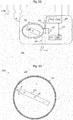
- Figure 1 schematically depicts a block diagram of a probe 100 according to an example.
- the probe 100 is suitable for use e.g. in the human body or in an animal body, e.g. for the purpose of disease management, or remote doctor control.
- the probe may be used for releasing products such as medical agents (drugs) into the body and/or for monitoring local body function parameters and/or for performing manipulations of body parts, as will be explained in detail further below.
- the probe 100 comprises a housing 110 and an element 120 having a permanent magnetic dipole moment.
- the element 120 having a permanent magnetic dipole moment is rotatably mounted within said housing 110, so that the element 120 having a permanent magnetic dipole moment may rotate, e.g., around an axis 122, as illustrated by the double arrow a1 of Fig. 1 .
- the housing 110 may be configured to protect the component(s) 120 in its interior I from influences of a surrounding medium (e.g., blood and/or body tissue), which may be present outside the housing, cf. reference numeral 200.
- a surrounding medium e.g., blood and/or body tissue
- the probe 100 further comprises an electrical circuit C, and the element 120 having a permanent magnetic dipole moment is configured to generate an electromotive force (EMF) in said electrical circuit C in response to being rotated.
- EMF electromotive force
- the probe 100 may advantageously enable to be wirelessly supplied with electrical energy from an external source (not shown).
- the external source may magnetically drive a rotating movement of the element 120 having a permanent magnetic dipole moment via time-varying magnetic fields generated and/or controlled by said external source.
- the element 120 having a permanent magnetic dipole moment within the probe may be set into rotation, which corresponds with a transfer of energy from said external magnetic field to rotational energy of said element 120 having a permanent magnetic dipole moment.
- the rotation of the element 120 having a permanent magnetic dipole moment generates said EMF in the electric circuit C, as mentioned above.
- this energy supply may be employed for wirelessly supplying the probe with electrical energy, e.g. by transforming the rotational energy of said element 120 having a permanent magnetic dipole moment at least partly into electrical energy within said probe, as stated above.
- the probe 100 may also wirelessly communicate with an external device, e.g., via the element 120 having a permanent magnetic dipole moment, as will be explained in detail further below.
- the probe 100 may not have or need a local storage medium for electric energy such as a battery or the like. Instead, operating energy may be provided from the external source via the element 120 having a permanent magnetic dipole moment, e.g., when the probe 100 is deployed in a human or animal body.
- the magnetic fields generated and/or controlled by said external source would not be substantially attenuated by the human or animal body.
- an efficient energy transfer and/or possibly wireless communication is enabled between the external source and the probe 100, e.g., even when the probe 100 is positioned deeply within the human or animal body.
- the probe may be used in other environments such as e.g. (biochemical) reactors, pipes, or another environment where a direct mechanical contact to said probe is at least temporarily impossible.
- environments such as e.g. (biochemical) reactors, pipes, or another environment where a direct mechanical contact to said probe is at least temporarily impossible.
- some examples rely on magnetic fields of low frequency to operate and/or communicate with the probe 100.
- the external magnetic field may have a frequency in the range between about 0 Hz and about a few kHz, e.g., depending on the dimensions of the element 120 having a permanent magnetic dipole moment.
- the element 120 having a permanent magnetic dipole moment is connected to the housing 110 via an elongated shaft, and the element 120 having a permanent magnetic dipole moment is able to rotate around an axial direction of said shaft ( Fig. 1 ).
- the connection to the housing via such a shaft may be such that the shaft functions as a type of "mechanical bearing", particularly internal bearing, for the element 120 having a permanent magnetic dipole moment.
- a shaft may e.g. be provided at the position of the schematically indicated axis of rotation 122.
- the probe 100 may include an external bearing providing a low friction connection of the element 120 having a permanent magnetic dipole moment to the housing 110 thus enabling a rotational motion of the element 120 having a permanent magnetic dipole moment within the housing 110.
- an external bearing providing a low friction connection of the element 120 having a permanent magnetic dipole moment to the housing 110 thus enabling a rotational motion of the element 120 having a permanent magnetic dipole moment within the housing 110.
- one or more axial end portions of said element 120 having a permanent magnetic dipole moment may be supported or guided within an annular groove provided e.g. on the inner surface of the housing device, also cf. the Fig. 3C embodiment further below.
- said element 120 having a permanent magnetic dipole moment comprises or consists of at least one permanent magnet, e.g. a bar magnet, cf. Fig. 1 , wherein preferably a maximum length dimension L1 of said magnet is smaller than about 15 millimeter (mm), preferably smaller than about 1.5 mm.
- a bar magnet may substantially comprise cuboid shape with a width a, a length b, and a depth c, wherein e.g. b > a and b > c, and wherein said length b e.g.
- L1 corresponds to the abovementioned maximum length dimension L1, wherein preferably b ⁇ 15 mm, or more preferably b ⁇ 1.5mm.
- the housing 110 of the probe 100 may be designed such that its outer dimension(s) is/are not substantially larger than said maximum length dimension L1 of the element 120 having a permanent magnetic dipole moment.
- Applicant believes further miniaturization of the element 120 having a permanent magnetic dipole moment and the complete probe 100 comprising said element 120 having a permanent magnetic dipole moment may be possible.
- a maximum linear dimension for the element 120 having a permanent magnetic dipole moment e.g. in the micrometer (pm) or even nanometer (nm) range may be possible.
- Such further miniaturization may enable the probe 100 according to the examples to have largest linear outer dimensions of e.g. few hundreds of micrometers or few hundreds of nanometers.
- magnetic material of the NdFeB-type i.e. comprising an alloy of neodymium (Nd), iron (Fe) and boron (B), e.g. Nd2Fe14B, may be used to form the element 120 having a permanent magnetic dipole moment and/or components thereof.
- Permanent magnets made of the above mentioned neodymium alloy may also be denoted as "supermagnets" due to their comparatively high remanent magnetic flux density.
- the abovementioned bar magnet type having cuboid shape is particularly preferred.
- the probe 100 may comprise an electronic control unit, cf. the dashed line block 130 of Fig. 1 .
- Said optional electronic control unit 130 may e.g. control an operation of the probe 100, e.g., by determining at least one of: a frequency and/or amplitude of the external magnetic field applied to propel the rotational movement of the element 120 having a permanent magnetic dipole moment, or a rotational speed of the element 120 having a permanent magnetic dipole moment in the probe 100.
- the electronic control unit 130 may e.g. comprise an ASIC (application specific integrated circuit), a microcontroller, a digital signal processor (DSP), discrete logic elements, a programmable logic circuit or any combination thereof.
- ASIC application specific integrated circuit
- DSP digital signal processor
- said electronic control unit 130 may wirelessly transmit control information to an external device, e.g. causing said external device to alter parameters (amplitude and/or frequency) of said time-varying magnetic fields from the external source.
- Fig. 2A depicts the probe 100 of Figures 1 according to a further embodiment 100a. While the configuration of its element 120 having a permanent magnetic dipole moment may be similar to the configuration of the probe 100 according to Fig. 1 , the probe 100a of Fig. 2A comprises an induction coil 140 located so that rotation of said rotatable element 120 having a permanent magnetic dipole moment produces an electromotive force (EMF) across said induction coil 140.
- EMF electromotive force
- a controllable electric resistor 142 may be connected electrically across said induction coil 140 so that the EMF produced in the induction coil 140 drives an electrical current in the resistor 142.
- the probe 100a of Fig. 2A comprises a control unit 132 that may have a structure similar to the (optional) electronic control unit 130 explained above with reference to Fig. 1 .
- the electronic control unit 132 of Fig. 2 is configured to control the resistor 142 or another electrical power dissipator and thereby the amount of electric energy dissipated within said resistor 142.
- the dissipation of said amount of electric energy causes a corresponding reduction of the rotational energy and thus, also can slow the rotational speed of the element 120 having a permanent magnetic dipole moment.
- the electronic control unit 132 may effect a corresponding modulation of the magnetic field generated by the rotating element 120 having a permanent magnetic dipole moment. Said modulation of the induced magnetic field may be detected by a magnetic receiver coil placed outside the probe 100a.
- data transfer from the probe 100a to an external device may be enabled by a data-stream-controlled modulation of the magnetic field induced by the element 120 having a permanent magnetic dipole moment.
- This modulation mechanism may enable data transfer rates of, at least, a kilobit-per-second, which may be sufficient, e.g., for transmitting measurement data from sensors (e.g., pressure, temperature and pH values) and the like in or on the exterior of the probe 100a.
- sensors e.g., pressure, temperature and pH values
- the resistor 142 may be controlled by a digital control circuit or an analog control circuit of the electronic control unit 132.
- a value for the electric resistance of the resistor 142 may range between 0 Ohms (short circuit) and open circuit, wherein preferably any intermediate values (or at least a minimum number of different intermediate values) may also be set by means of analog or digital control.
- any intermediate values or at least a minimum number of different intermediate values
- the energy extraction from the element 120 having a permanent magnetic dipole moment by the induction coil 140 may be controllable.
- the probe 100a may comprise one or more sensors 150, which may be, e.g., partly integrated into the housing 110 of the probe 100a, and which may be configured to measure one or more physical parameters P of the probe 100a and/or a medium 200 surrounding the probe 100a, e.g., temperature, pressure, pH value, pulse rate, and the like and/or may provide image(s) of the local environment.
- the control unit 132 may process sensor signals and/or data provided by said sensors 150. Also, the sensor signals or any data derived therefrom may be transmitted to an external device, e.g. by modulating a controllable version of the electric resistor 142 and thus, by modulating an angular speed of the element 120 having a permanent magnetic dipole moment as already explained above.
- an analog or digital control circuit receiving sensor signal(s) from said sensor(s) 150 and directly controlling the resistor 142 depending thereon.
- Fig. 2B depicts a probe 100 of Fig. 1 according to a further example 100b. While the configuration of the element 120 having a permanent magnetic dipole moment and the induction coil 140 and the resistor 142 may be similar or identical to the configuration of the probe 100a according to Fig. 2A , the probe 100b of Fig. 2B additionally comprises an energy storage unit 134 for, at least, temporarily storing electrical energy derived from the rotational movement of the element 120 having a permanent magnetic dipole moment.
- the energy storage unit 134 may be connected in parallel to the induction coil 140 and the resistor 142, cf. the lines 144 so that an EMF magnetically induced across the induction coil 140 can electrically drive currents in the resistor 142 and the energy storage unit 134.
- the energy storage unit 134 may comprise a rectifier circuit 134a for rectifying a voltage induced into the induction coil 140 and a power stabilizer circuit 134b for buffering a rectified voltage provided at an output of the rectifier circuit 134a.
- the power stabilizer circuit 134b may e.g. comprise a capacitor, for example a double-layer capacitor ("ultracap").
- a control device 132' may be provided receiving sensor signals from optional sensors 150. Also, the control device may monitor a voltage output by the power stabilizer circuit 134b, cf. double arrow 135, and may control operation of the resistor 142 for transmitting data to an external device (not shown).
- the control device 132' may further be configured to receive information transmitted by an external device, e.g. a device providing the external magnetic field for driving rotational movement of the element 120 having a permanent magnetic dipole moment.
- a control signal controlling said external magnetic field may be modulated (e.g., by said external device), similarly to the mechanism explained above with reference to the resistor 142 or in any other way enabling modulation of said external magnetic field, and such modulation may be detected by the control device 132'.
- This mechanism may be used for transmitting data and/or control commands to and/or from an external device from and/or to the control unit 132' of the probe 100b.
- such one-direction or two-direction communication of data and/or control instructions have proceeded at rates, e.g., in the range of, at least, several kilobits per seconds.
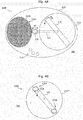
- Figure 3A schematically depicts a probe 100c according to a further example.
- the probe 100c has a substantially spherical shape, and an element 120 having a permanent magnetic dipole moment is rotatably arranged (cf. double arrow a1) within a housing 110.
- the element 120 having a permanent magnetic dipole moment may have the form of a bar magnet type, e.g. having substantially cuboid or parallelepiped shape.
- Exemplarily the magnetic north and south poles of the element 120 having a permanent magnetic dipole moment are also indicated in Fig. 3A .
- a ellipsoidal shape or further shapes are also possible for the housing 110.
- the element 120 having a permanent magnetic dipole moment comprises an inner bearing implemented by means of a shaft arranged at the position of the axis of rotation 122, wherein said shaft is mounted to an interior I of the housing 110.
- FIG. 3B depicts a further example 100d of the probe 100 of Fig. 1 , wherein said element 120 having a permanent magnetic dipole moment comprises an external bearing.
- said element 120 having a permanent magnetic dipole moment comprises an external bearing.
- the element 120 having a permanent magnetic dipole moment is also rotatably arranged (cf. double arrow a2) around a (virtual) axis of rotation 122a.
- said inner surface 110a may comprise a suitable material and/or coating or the like which exhibits sufficient gliding properties with the axial end sections of the element having a permanent magnetic dipole moment.
- the element 120 having a permanent magnetic dipole moment or at least its axial end sections 120a, 120b may be coated with a material having good gliding properties with respect to the inner surface 110a.
- Fig. 3C depicts yet another example 100e of the probe 100 of Fig. 1 , wherein an annular groove 110b is provided within the inner surface 110a of the housing, said annular groove 110b guiding the axial end sections 120a, 120b of the element 120 having a permanent magnetic dipole moment, thus again constituting an external bearing for said element 120 having a permanent magnetic dipole moment.
- a rotational movement of the element 120 having a permanent magnetic dipole moment basically occupies a circular disc shaped volume portion of the basically spherical interior I of the housing 110, for example basically centered around the drawing plane of Fig. 3C
- other volume regions of the interior I of the housing 110 e.g. further away from the drawing plane of Fig. 3C , may be used for integrating components such as induction coil(s) 140, control unit(s) 130, 132, 132' and the like.
- one or more induction coil(s) may also be placed on the inner surface ( Fig. 3A ) of the housing 110.
- the element 120 having a permanent magnetic dipole moment is preferably formed such that it comprises a mass distribution symmetrical to its axis of rotation, to avoid vibrations and energy losses caused by undesired vibrations.
- the element 120 having a permanent magnetic dipole moment with an asymmetric mass distribution with respect to its axis of rotation to enable vibrations of said element 120 having a permanent magnetic dipole moment and the probe 100e containing it to be generated by driving rotational movement of the element 120 having a permanent magnetic dipole moment.
- This enables to introduce structure-borne noise (ranging from low frequencies of a few Hz up to ultrasonic frequency ranges of several tens of kHz) into an area surrounding the probe 100e, e.g. for effecting movement or even local heating of a surrounding medium.
- the housing 110 is hermetically sealed, so that no fluids (liquids and/or gases) surrounding the probe 100e may enter the interior I.
- the interior I may comprise a vacuum or at least a partial vacuum, which ensures substantially unimpeded rotational movement of the element 120 having a permanent magnetic dipole moment.
- the interior I of the probe 100e may also comprise a gas and/or a liquid, e.g. for supporting the element having a permanent magnetic dipole moment.
- a gas or liquid within said interior I which comprises a sufficiently low viscosity in order not to impede rotational movement of the element having a permanent magnetic dipole moment.
- a partial vacuum or a total vacuum may also be contemplated.
- FIG 4A schematically depicts a probe 100f according to a further embodiment of the probe 100 of Fig. 1 .
- the probe 100f comprises an element 120 having a permanent magnetic dipole moment rotatably arranged in a housing 110, cf. double arrow a3.
- the housing 110 is arranged in a capsule 110', which also comprises a container 111a comprising an agent 111b such as a drug which is to be released from the capsule 110' inside a human body.
- the element 120 having a permanent magnetic dipole moment is coupled to a first axial end section of a shaft 124, which defines an axis of rotation of the element 120 having a permanent magnetic dipole moment.
- a second axial end section of the shaft 124 protrudes from the housing 110 and comprises a drilling tip 126 which is coupled to the shaft 124 in a torque-proof manner (cf. double arrow a4 indicating rotation of the drilling tip 126) so that the drilling tip 126 will open the container 111a once the element 120 having a permanent magnetic dipole moment drives the shaft 124.
- the agent 111b comprised in the container 111a may be set free within the capsule 110' in a controlled manner, i.e. by activating rotational movement of the element 120 having a permanent magnetic dipole moment by application of a corresponding external magnetic field.
- said capsule 110' may comprise one or more openings 110" so that the agent - once set free from its container 111a - may leave the capsule 110' and reach a target area 202 surrounding the capsule 110'.
- the wall material of the capsule 110' may be configured such that human or animal tissue may substantially not enter the interior of the capsule, but such that an agent carried within container 111a may be released through said wall.
- Figure 4B schematically depicts a probe 100g according to a further example of the probe 100 of Fig. 1 .
- the element 120 having a permanent magnetic dipole moment carries at its axial end sections blades or other structures suitable of severing a material of the housing 110"' once the element 120 having a permanent magnetic dipole moment is rotating, cf. arrow a5.
- an agent such as a drug (not shown) arranged in the interior I of the probe 100g may be controllably set free by activation of rotation of the element 120 having a permanent magnetic dipole moment once the probe 100g is positioned within a target region 200 e.g. within a human body.
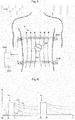
- Figure 5 schematically depicts an operational scenario of a system 1000 that uses any embodiment of the probe 100 of Fig. 1 in a human or animal body B.
- the probe 100 is illustrated as being positioned within a gastrointestinal (GI) tract 202 of the body B.
- GI gastrointestinal
- Such position may e.g. be attained by oral insertion and travel of the probe 100 to the illustrated position in the GI tract, or by injection, or by locally inserting the probe 100 by using another (e.g., conventional) probe for analyzing a human body's GI tract.
- GI gastrointestinal
- the probe 100 may e.g. comprise any of the examples 100a, 100b, 100c, 100d, 100e, 100f, and 100g as explained above with reference to the Figures 1 to 4B or any combination thereof.
- the system 1000 comprises a magnetic field generator having a control unit 1010 and a pair of Helmholtz coils 1002, 1004 arranged outside and around the GI region of the human or animal body B, e.g., completely outside of the body B.
- the Helmholtz coils 1002, 1004 may easily be put in place around the human or animal body B e.g. by sliding them axially over the body.
- one or more coils connected to said control unit 1010 could also be placed in a piece of clothing such as e.g. a vest, which may be put on by a patient prior to operating the system 1000.
- the Helmholtz coils 1002, 1004 may e.g. be used to provide a basically homogenous static or time variable magnetic field H therebetween in a per se known manner.
- a control current for this may be provided by the control unit 1010.
- the application of the magnetic field H will cause the magnetic dipole moment of the element 120 having a permanent magnetic dipole moment ( Fig. 1 ) of the probe 100 to significantly or substantially align with the field lines (static case) or to rotate (dynamic case), e.g. depending on a frequency of the alternating magnetic field H.
- the element 120 having a permanent magnetic dipole moment which may preferably be a "supermagnet” (i.e., with high remanent magnetic flux density), interacts with the externally generated magnetic field H, whereby a type of "synchronous motor” may be formed, wherein the element 120 having a permanent magnetic dipole moment corresponds to the rotor of the "synchronous motor” and wherein the Helmholtz coils 1002, 1004 correspond to the stator of the "synchronous motor”.
- employing the principle of the various embodiments enables to efficiently transfer energy from outside the probe 100, even from outside the human or animal body B, to the probe 100, which is placed inside the body B, without requiring any electrical connections to the body.
- the "stator” i.e., the coils 1002, 1004
- the "rotor” namely the element 120 having a permanent magnetic dipole moment, as a micro- or even nanoscale component thus offering increased operational flexibility such as drug delivery or other probe applications directly within smaller blood vessels or other parts of the human or animal body B where conventional probes cannot be used due to their size.
- an energy flow to the probe 100 may be controlled from the outside, thus externally triggering effects for in-body actuation and even signal transmission into and out of the body are possible as already discussed.
- control unit 1010 may be configured to provide an alternating magnetic field for driving rotational movement of the element 120 having a permanent magnetic dipole moment of the probe 100 ( Fig. 5 ) inside the body B.
- control unit 1010 may be configured to provide a rotating magnetic field.
- rotating magnetic fields can be generated.
- a rotational speed of the element 120 having a permanent magnetic dipole moment is determined by a frequency of a periodic field change of the magnetic field H generated by the coils 1002, 1004.
- the element 120 having a permanent magnetic dipole moment ( Fig. 1 ) of the probe 100 may be aligned with said static magnetic field H, which may e.g. be used for moving the element 120 having a permanent magnetic dipole moment in a defined position with respect to the coils 1002, 1004.
- said static magnetic field H which may e.g. be used for moving the element 120 having a permanent magnetic dipole moment in a defined position with respect to the coils 1002, 1004.
- the element 120 having a permanent magnetic dipole moment has basically cuboid shape with a length L1 of about 5 mm, and a width and depth of each about 1 mm.
- the volume V of the element 120 having a permanent magnetic dipole moment is thus about 5 x 10 -9 m 3 .
- the magnetic remanence flux density Br is assumed to equal about 1,47 T (Tesla), which may e.g. be attained by using magnet material of the NdFeB "N50H" type.
- the magnetic field generator 1002, 1004, 1010 exemplarily depicted by Fig. 5 is configured to, in a first operational state, provide a temporally alternating magnetic field, particularly to drive a rotational movement of the element 120 having a permanent magnetic dipole moment of said at least one probe 100, wherein optionally, said magnetic field generator 1002, 1004, 1010 is configured to, in a second operational state, provide a substantially static magnetic field, particularly to align the element 120 having a permanent magnetic dipole moment of said at least one probe 100 in a predetermined direction depending on said substantially static magnetic field.
- the first operational state may be employed to supply the probe 100 with mechanical energy
- the second operational state may be used to align the element 120 having a permanent magnetic dipole moment with the magnetic field provided in said second operational state, e.g. to establish a defined starting position prior to entering the first operational mode.
- said system 1000 comprises an optional receiver 1012 configured to receive an alternating magnetic signal from the element 120 having a permanent magnetic dipole moment of said probe 100.
- Said receiver 1012 may e.g. comprise a distinct magnetic coil capable of detecting a time variable magnetic flux generated by the rotating element having a permanent magnetic dipole moment of the probe 100.
- one or more of the coils 1002, 1004 of the magnetic field generator 1002, 1004, 1010 may also be used for detecting a time variable magnetic flux generated by the rotating element having a permanent magnetic dipole moment of the probe 100, e.g. in a time division duplexed manner with respect to generating a magnetic field for driving rotational movement of the element having a permanent magnetic dipole moment.
- the probe 100 may transmit information to the receiver 1012.
- the embodiments 100a, 100b of Fig. 2A , 2B may influence the rotational movement of their element 120 having a permanent magnetic dipole moment by means of the electromagnetically coupled induction coil 140 and the controllable resistor 142, as already explained above.
- Figure 6 schematically depicts an example of a time diagram of operational parameters of the system 1000 according to Figure 5 .
- Reference sign t0 indicates a starting time at which the probe 100 is deployed in the GI tract of the body B ( Fig. 5 ) and is ready for operation.
- a control signal cs indicates by means of two pulses P1, P2 two time intervals (t1, t2), (t3, t4) during which an alternating magnetic field H ( Fig. 5 ) is generating by the magnetic field generator 1002, 1004, 1010. More specifically, this is achieved by applying corresponding alternating currents to both Helmholtz coils 1002, 1004 using the control unit 1010. During the further time intervals (t0, t1), (t2, t3) and after time t4, no magnetic field is generated.
- the alternating magnetic field H applied during e.g. the time interval (t1, t2) causes a rotational movement of the element 120 having a permanent magnetic dipole moment of the probe 100 ( Fig. 5 ), wherein a rotational speed depends on the frequency of the alternating magnetic field H.
- the rotational speed of the element 120 having a permanent magnetic dipole moment will decrease, primarily due to friction losses.
- this scenario repeats.
- a controllable damping which may be attained by the induction coil 140 and the damping resistor 142, cf. e.g. the configuration of the probe depicted by Fig. 2A , may also influence the decrease of the rotational speed of the element 120 having a permanent magnetic dipole moment after the pulse(s) P1, P2.
- Fig. 6 depicts three curves rs1, rs2, rs3 for potential variations in time of the rotational speed of the elements having a permanent magnetic dipole moment caused by different damping actions by means of the elements 140, 142.
- these different variations in time may be detected by the receiver 1012, which may e.g.
- one or more of the Helmholtz coils 1002, 1004 could be used by the receiver 1012 as receiver coils for measuring the induction voltage induced by the magnetic field of the rotating element 120 having a permanent magnetic dipole moment.
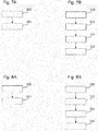
- Figure 7A schematically depicts a simplified flow-chart of a method of operating a probe according to the discussed examples.
- the probe receives energy from an external magnetic field, e.g. field H as depicted by Fig. 5 .
- a drive torque resulting from the external magnetic field in combination with the non-vanishing magnetic dipole moment of the element 120 having a permanent magnetic dipole moment drives rotational movement of said element 120 having a permanent magnetic dipole moment, cf. double arrow a1 of Fig. 1 .
- at least a portion of the energy received from the external magnetic field H is transformed to mechanical, e.g. rotational, energy of the element 120 having a permanent magnetic dipole moment within the probe according to the embodiments.
- step 302 at least a portion of the so received energy may be used for a specific action such as conversion to electric energy and/or thermal energy or sound waves, e.g. ultrasonic waves, or for driving an actuator of which the probe 100 is equipped.
- FIG. 7B schematically depicts a simplified flow-chart of a method of operating a probe 100b ( Fig. 2B ) according to a further example.
- the probe 100b receives energy from the externally generated magnetic field H ( Fig. 5 ). Also in this step 310, at least a portion of said received energy is transformed into electric energy and temporarily stored or buffered by means of the energy storage unit 134.
- the probe 100b receives a control command from the control unit 1010, wherein said control command is e.g. provided by modulating the alternating magnetic field in a way than can be detected and demodulated by the local control device 132' of the probe 100b. Said control command may e.g.
- the probe 100b or its local control device 132' instruct the probe 100b or its local control device 132', respectively, to evaluate a signal of a sensor 150 comprised within the probe 100b in order to obtain a measurement value, e.g. a pressure value of a medium surrounding the probe 100b. This is done in subsequent step 314 of Fig. 7B .
- the measured pressure value is transmitted from the probe 100b to the external device 1010 or its receiver 1032, respectively, in step 316 ( Fig. 7B ) by modulating an inductive damping of the rotating element 120 having a permanent magnetic dipole moment ( Fig. 2B ) by means of the resistor 142, as explained above with reference to Fig. 6 .
- the probe may also comprise a, preferably non-volatile, memory unit 136 for storing measurement values obtained from the sensor(s) 150 ( Fig. 2B ), wherein said memory unit may e.g. be included in a control device 132'.
- FIG. 8A schematically depicts a simplified flow-chart of a method of operating a system 1000 ( Fig. 5 ) according the embodiments.
- the magnetic field generator 1002, 1004, 1010 ( Fig. 5 ) of the system 1000 assumes a second operational state in which a substantially static magnetic field H is generated to align the element 120 having a permanent magnetic dipole moment ( Fig. 1 ) of the probe 100 in a predetermined direction with respect to said static magnetic field H.
- the magnetic field generator 1002, 1004, 1010 Fig.
- a temporally alternating magnetic field H is generated to drive a rotational movement of the element 120 having a permanent magnetic dipole moment of the probe, which may e.g. be used for continued energy supply of the probe 100.
- step 320 of aligning may be omitted, according to other embodiments it may be particularly beneficial as it improves an efficient initialization of rotational movement within the first operating state 322.
- Figure 8B schematically depicts a simplified flow-chart of a method of operating a system 1000 ( Fig. 5 ) according to a further example.
- the probe may comprise elements of the embodiment of Fig. 2B and of the embodiment of Fig. 4A .
- the magnetic field generator 1002, 1004, 1010 ( Fig. 5 ) of the system 1000 assumes its first operational state in which a temporally alternating magnetic field H is generated to drive a rotational movement of the element 120 having a permanent magnetic dipole moment of the probe.
- the control unit 1010 transmits a control command to the probe instructing it to start a measurement, e.g. using a sensor 150.
- the probe After the measurement, the probe transmits the measured value to the control unit 1010, which may also be performed in step 332.
- the control unit 1010 receives the measured value by means of its receiver 1012.
- the control unit 1010 transmits a further control command to the probe instructing it to release a drug into the surroundings of the probe. This may e.g. be attained using the techniques explained above with respect to Fig. 4A, 4B .
- the probe and the system according to the examples may advantageously be used in the fields of disease management, remote doctor control, personal wellness, but they are not limited to applications in the human or animal body.
- sensors and/or actuators may be provided for use within the human and/or animal body (or in any other target system) in combination with the probe according to the embodiments, which enables a direct energy supply of said sensors and/or actuators from the outside, by means of the system 1000 according to the examples.
- the probe may be equipped with (conventional) sensors and/or actuators and provides them with the power required for operating within the human and/or animal body, without requiring direct electric connections to the probe and/or to the sensors and/or actuators themselves.
- the probe may be implantable and/or injectable and/or ingestible.
- the probe according to the examples may e.g. be designed as a nanoscale, microscale or larger device, as it is possible to manufacture elements 120 having a permanent magnetic dipole moment according to the embodiments with nanoscale, microscale, or larger linear dimension(s), because particularly NdFeB-based magnets have a fine-crystalline structure.
- a fabrication process for elements 120 having a permanent magnetic dipole moment may comprise steps of milling the raw materials, compression of the so obtained powder, and finally sintering of the magnetic material.
- the elements having a permanent magnetic dipole moment are superior for in-body use as they enable to provide nano- or microscale elements 120 having a permanent magnetic dipole moment enabling efficient energy transfer from outside the body into a probe positioned within the body.
- the rotation of such elements having magnetic dipole moments with linear dimensions in the micrometer-range and larger in a fluid can be performed in a controlled way by applying suitable external magnetic fields.
- said external magnetic fields may e.g. comprise magnetic flux densities in the range of about few ⁇ T (microtesla) up to about few mT (millitesla).
- the principle according to the examples may be used for targeted in-body drug delivery, gaining diagnostics information, and also for taking biopsy samples, as it enables energy supply of and information exchange with nano-/microscale probes inside the body.
- the principle according to the examples enables an efficient data transfer between an external device 1010 ( Fig. 5 ) and the probe 100, even if the probe 100 is positioned deeply within body tissue.
- the principle according to the examples advantageously enables to directly use mechanical energy, e.g. obtained at a shaft 124 ( Fig. 4A ) driven by the element 120 having a permanent magnetic dipole moment, thus avoiding conversion losses which would occur with transformation to other forms of energy. Also, in-body battery use may be avoided according to some examples.
- the principle according to the embodiments is particularly beneficial because it provides for a direct supply with mechanical energy within the probe 100, even if such device comprises micro- or nanoscale dimensions.
Landscapes
- Engineering & Computer Science (AREA)
- Health & Medical Sciences (AREA)
- Life Sciences & Earth Sciences (AREA)
- Computer Networks & Wireless Communication (AREA)
- Animal Behavior & Ethology (AREA)
- Veterinary Medicine (AREA)
- Biomedical Technology (AREA)
- Public Health (AREA)
- General Health & Medical Sciences (AREA)
- Medical Informatics (AREA)
- Surgery (AREA)
- Molecular Biology (AREA)
- Pathology (AREA)
- Heart & Thoracic Surgery (AREA)
- Biophysics (AREA)
- Physics & Mathematics (AREA)
- Power Engineering (AREA)
- Nuclear Medicine, Radiotherapy & Molecular Imaging (AREA)
- Radiology & Medical Imaging (AREA)
- Endoscopes (AREA)
- Magnetic Treatment Devices (AREA)
Claims (12)
- Vorrichtung zur Verwendung in einem menschlichen oder tierischen Körper, umfassend eine Sonde (100; 100a; 100b; 100c; 100d; 100e; 100f; 100g), wobei die Sonde ein Gehäuse (110), mindestens ein Element (120) mit einem permanentmagnetischen Dipolmoment, das innerhalb des Gehäuses (110) drehbar ist, und eine elektrische Schaltung (C) umfasst, wobei die Schaltung (C) mindestens eine Induktionsspule (140), die magnetisch mit dem Element (120) mit einem permanentmagnetischen Dipolmoment gekoppelt ist, und einen steuerbaren elektrischen Widerstand (142) umfasst, der parallel zur Induktionsspule (140) geschaltet ist, wobei das Element mit einem permanentmagnetischen Dipolmoment dazu eingerichtet ist, eine elektromotorische Kraft in der mindestens einen Induktionsspule (140) als Reaktion auf eine Drehung zu erzeugen, wobei die Sonde dazu eingerichtet ist, Daten drahtlos durch Modulieren eines Widerstandswertes des Widerstandes (142) an eine externe Einrichtung zu übertragen.
- Vorrichtung nach Anspruch 1, wobei das Element (120) mit einem permanentmagnetischen Dipolmoment eine maximale Längenabmessung (L1) von weniger als etwa 15 Millimeter aufweist.
- Vorrichtung nach einem der vorhergehenden Ansprüche, wobei das Element (120) eine remanente magnetische Flussdichte von mindestens etwa 0,1 Tesla aufweist.
- Vorrichtung nach einem der vorhergehenden Ansprüche, ferner umfassend eine elektrische Steuereinheit (130; 132; 132') in dem Gehäuse (110).
- Vorrichtung nach einem der vorhergehenden Ansprüche, wobei das Gehäuse (110) eine im Wesentlichen ellipsoidische oder kugelförmige Form aufweist.
- Vorrichtung nach einem der vorhergehenden Ansprüche, wobei die Sonde (100; 100a; 100b; 100c; 100d; 100e; 100f; 100g) eine Einrichtung zum Umwandeln mechanischer Rotationsenergie des Elements (120) mit einem permanentmagnetischen Dipolmoment in einen das Gehäuse (110) der Sonde umgebenden Fluss einer Flüssigkeit und/oder zum Umwandeln mechanischer Rotationsenergie des Elements (120) mit einem permanentmagnetischen Dipolmoment in Bewegung der Sonde und/oder zum Umwandeln der mechanischen Rotationsenergie des Elements (120) mit einem permanentmagnetischen Dipolmoment in akustische Energie aufweist.
- Vorrichtung nach einem der vorhergehenden Ansprüche, wobei die Sonde (100; 100a; 100b; 100c; 100d; 100e; 100f; 100g) dazu eingerichtet ist, mindestens ein daraus freisetzbares Medikament in den menschlichen oder tierischen Körper zu bringen.
- Verfahren zum Betreiben der Vorrichtung nach Anspruch 1, wobei die Sonde drahtlos Daten an die externe Einrichtung durch Modulieren eines Widerstandswertes des Widerstandes (142) überträgt.
- Verfahren nach Anspruch 8, wobei die Sonde (100; 100a; 100b; 100c; 100d; 100e; 100f; 100g) mechanische Rotationsenergie des Elements (120) mit einem permanentmagnetischen Dipolmoment in mindestens eines von Folgendem umwandelt: a) elektrische Energie, b) thermische Energie, c) Fluss einer das Gehäuse (110) der Sonde (100; 100a; 100b; 100c; 100d; 100e; 100f; 100g) und/oder innerhalb des Gehäuses (110) der Sonde (100; 100a; 100b; 100c; 100d; 100e; 100f; 100g) umgebenden Flüssigkeit, d) Vortriebsenergie zum Bewegen der Sonde (100; 100a; 100b; 100c; 100d; 100e; 100f; 100g), e) akustische Energie.
- System (1000), umfassend eine Vorrichtung mit mindestens einer Sonde (100; 100a; 100b; 100c; 100d; 100e; 100f; 100g) nach einem der Ansprüche 1 bis 7 und einen Magnetfeldgenerator (1002, 1004, 1010), der dazu eingerichtet ist, ein zeitlich veränderliches Magnetfeld (H) in der mindestens einen Sonde (100; 100a; 100b; 100c; 100d; 100e; 100f; 100g) zu erzeugen.
- System (1000) nach Anspruch 10, wobei der Magnetfeldgenerator (1002, 1004, 1010) dazu eingerichtet ist, ein im Wesentlichen statisches Magnetfeld (H) zu liefern, um das Element (120) mit einem permanentmagnetischen Dipolmoment in einer ausgewählten Richtung auszurichten.
- System (1000) nach einem der Ansprüche 10 bis 11, wobei das System (1000) einen Empfänger (1012) umfasst, der dazu eingerichtet ist, einen Datenstrom von dem Element (120) zu empfangen.
Priority Applications (1)
| Application Number | Priority Date | Filing Date | Title |
|---|---|---|---|
| EP16306359.7A EP3308698B1 (de) | 2016-10-14 | 2016-10-14 | Sonde und verfahren zum betrieb einer sonde |
Applications Claiming Priority (1)
| Application Number | Priority Date | Filing Date | Title |
|---|---|---|---|
| EP16306359.7A EP3308698B1 (de) | 2016-10-14 | 2016-10-14 | Sonde und verfahren zum betrieb einer sonde |
Publications (2)
| Publication Number | Publication Date |
|---|---|
| EP3308698A1 EP3308698A1 (de) | 2018-04-18 |
| EP3308698B1 true EP3308698B1 (de) | 2020-02-26 |
Family
ID=57206186
Family Applications (1)
| Application Number | Title | Priority Date | Filing Date |
|---|---|---|---|
| EP16306359.7A Active EP3308698B1 (de) | 2016-10-14 | 2016-10-14 | Sonde und verfahren zum betrieb einer sonde |
Country Status (1)
| Country | Link |
|---|---|
| EP (1) | EP3308698B1 (de) |
Family Cites Families (4)
| Publication number | Priority date | Publication date | Assignee | Title |
|---|---|---|---|---|
| JP2009539065A (ja) * | 2006-05-16 | 2009-11-12 | トリプル センサー テクノロジース ゲーエムベーハー | 少なくとも1個の磁性体の非接触の定義された運動のための構造 |
| CN103904787B (zh) * | 2007-10-11 | 2017-06-06 | 高通股份有限公司 | 使用磁机械系统的无线功率转移 |
| CA2752096C (en) * | 2009-02-26 | 2016-08-09 | The University Of British Columbia | Systems and methods for dipole enhanced inductive power transfer |
| WO2016010772A2 (en) * | 2014-07-17 | 2016-01-21 | The University Of Florida Research Foundation, Inc. | Wireless power transfer using one or more rotating magnets in a receiver |
-
2016
- 2016-10-14 EP EP16306359.7A patent/EP3308698B1/de active Active
Non-Patent Citations (1)
| Title |
|---|
| None * |
Also Published As
| Publication number | Publication date |
|---|---|
| EP3308698A1 (de) | 2018-04-18 |
Similar Documents
| Publication | Publication Date | Title |
|---|---|---|
| JP2023040157A (ja) | 粒子と移植可能デバイスを制御する方法およびシステム | |
| JP5756085B2 (ja) | 血管内超音波イメージングシステムのためのカテーテルアセンブリ | |
| CN104023631B (zh) | 可移动的胶囊装置 | |
| JP4542326B2 (ja) | カプセル型医療装置誘導システム | |
| US8496573B2 (en) | Steerable capsule apparatus and method | |
| US9450446B2 (en) | Connector-free magnetic charger/winder | |
| US20110071401A1 (en) | Systems and methods for making and using a stepper motor for an intravascular ultrasound imaging system | |
| US10218221B2 (en) | Wireless power transfer using one or more rotating magnets in a receiver | |
| WO2009088062A1 (ja) | 感温磁性体を用いた温度計測方法及び温度制御方法 | |
| CN101169212A (zh) | 一种永磁微型机器人 | |
| US20210275269A1 (en) | Magnetic propulsion mechanism for magnetic devices | |
| US20090174400A1 (en) | Arrangement for Non-Contact Defined Movement of at Least One Magnetic Body | |
| JP2005131408A5 (de) | ||
| EP3308698B1 (de) | Sonde und verfahren zum betrieb einer sonde | |
| Kim et al. | A pushing force mechanism of magnetic spiral-type machine for wireless medical-robots in therapy and diagnosis | |
| KR100971013B1 (ko) | 자기공명장비용 모터 및 그 제어방법 | |
| JP7822635B2 (ja) | 磁気動力プローブおよびその使用方法 | |
| US20190246948A1 (en) | Probe Device and Method of Operating a Probe Device | |
| Zhang et al. | Development of a magnetically-actuated capsule robot for biopsy sampling using sma | |
| US20110127996A1 (en) | Apparatus and method for determining the roll angle of a device with a housing | |
| EP4142125A1 (de) | Miniaturisierter elektromagnetischer drehantrieb | |
| BO et al. | A new magnetic control method for spiral-type wireless capsule endoscope | |
| CN106606360B (zh) | 医用自给式轴向驱动装置及其使用方法 | |
| Ishiyama | Magnetic Actuator Works in Your Body¡—For Low Invasive Surgery— | |
| Xu et al. | Design of Selectively Controllable Micro Actuators Powered by Remote Resonant Magnetic Fields |
Legal Events
| Date | Code | Title | Description |
|---|---|---|---|
| PUAI | Public reference made under article 153(3) epc to a published international application that has entered the european phase |
Free format text: ORIGINAL CODE: 0009012 |
|
| STAA | Information on the status of an ep patent application or granted ep patent |
Free format text: STATUS: THE APPLICATION HAS BEEN PUBLISHED |
|
| AK | Designated contracting states |
Kind code of ref document: A1 Designated state(s): AL AT BE BG CH CY CZ DE DK EE ES FI FR GB GR HR HU IE IS IT LI LT LU LV MC MK MT NL NO PL PT RO RS SE SI SK SM TR |
|
| AX | Request for extension of the european patent |
Extension state: BA ME |
|
| STAA | Information on the status of an ep patent application or granted ep patent |
Free format text: STATUS: REQUEST FOR EXAMINATION WAS MADE |
|
| 17P | Request for examination filed |
Effective date: 20181018 |
|
| RBV | Designated contracting states (corrected) |
Designated state(s): AL AT BE BG CH CY CZ DE DK EE ES FI FR GB GR HR HU IE IS IT LI LT LU LV MC MK MT NL NO PL PT RO RS SE SI SK SM TR |
|
| RIC1 | Information provided on ipc code assigned before grant |
Ipc: A61B 5/07 20060101ALI20190723BHEP Ipc: H02J 7/02 20160101ALN20190723BHEP Ipc: H04B 5/00 20060101ALN20190723BHEP Ipc: H01F 3/10 20060101ALN20190723BHEP Ipc: H02J 5/00 20160101ALN20190723BHEP Ipc: A61B 5/00 20060101AFI20190723BHEP Ipc: A61N 1/378 20060101ALI20190723BHEP |
|
| GRAP | Despatch of communication of intention to grant a patent |
Free format text: ORIGINAL CODE: EPIDOSNIGR1 |
|
| STAA | Information on the status of an ep patent application or granted ep patent |
Free format text: STATUS: GRANT OF PATENT IS INTENDED |
|
| INTG | Intention to grant announced |
Effective date: 20190904 |
|
| GRAS | Grant fee paid |
Free format text: ORIGINAL CODE: EPIDOSNIGR3 |
|
| GRAA | (expected) grant |
Free format text: ORIGINAL CODE: 0009210 |
|
| STAA | Information on the status of an ep patent application or granted ep patent |
Free format text: STATUS: THE PATENT HAS BEEN GRANTED |
|
| AK | Designated contracting states |
Kind code of ref document: B1 Designated state(s): AL AT BE BG CH CY CZ DE DK EE ES FI FR GB GR HR HU IE IS IT LI LT LU LV MC MK MT NL NO PL PT RO RS SE SI SK SM TR |
|
| REG | Reference to a national code |
Ref country code: GB Ref legal event code: FG4D |
|
| REG | Reference to a national code |
Ref country code: CH Ref legal event code: EP |
|
| REG | Reference to a national code |
Ref country code: DE Ref legal event code: R096 Ref document number: 602016030493 Country of ref document: DE |
|
| REG | Reference to a national code |
Ref country code: AT Ref legal event code: REF Ref document number: 1236643 Country of ref document: AT Kind code of ref document: T Effective date: 20200315 |
|
| REG | Reference to a national code |
Ref country code: IE Ref legal event code: FG4D |
|
| PG25 | Lapsed in a contracting state [announced via postgrant information from national office to epo] |
Ref country code: NO Free format text: LAPSE BECAUSE OF FAILURE TO SUBMIT A TRANSLATION OF THE DESCRIPTION OR TO PAY THE FEE WITHIN THE PRESCRIBED TIME-LIMIT Effective date: 20200526 Ref country code: RS Free format text: LAPSE BECAUSE OF FAILURE TO SUBMIT A TRANSLATION OF THE DESCRIPTION OR TO PAY THE FEE WITHIN THE PRESCRIBED TIME-LIMIT Effective date: 20200226 Ref country code: FI Free format text: LAPSE BECAUSE OF FAILURE TO SUBMIT A TRANSLATION OF THE DESCRIPTION OR TO PAY THE FEE WITHIN THE PRESCRIBED TIME-LIMIT Effective date: 20200226 |
|
| REG | Reference to a national code |
Ref country code: NL Ref legal event code: MP Effective date: 20200226 |
|
| REG | Reference to a national code |
Ref country code: LT Ref legal event code: MG4D |
|
| PG25 | Lapsed in a contracting state [announced via postgrant information from national office to epo] |
Ref country code: IS Free format text: LAPSE BECAUSE OF FAILURE TO SUBMIT A TRANSLATION OF THE DESCRIPTION OR TO PAY THE FEE WITHIN THE PRESCRIBED TIME-LIMIT Effective date: 20200626 Ref country code: HR Free format text: LAPSE BECAUSE OF FAILURE TO SUBMIT A TRANSLATION OF THE DESCRIPTION OR TO PAY THE FEE WITHIN THE PRESCRIBED TIME-LIMIT Effective date: 20200226 Ref country code: SE Free format text: LAPSE BECAUSE OF FAILURE TO SUBMIT A TRANSLATION OF THE DESCRIPTION OR TO PAY THE FEE WITHIN THE PRESCRIBED TIME-LIMIT Effective date: 20200226 Ref country code: LV Free format text: LAPSE BECAUSE OF FAILURE TO SUBMIT A TRANSLATION OF THE DESCRIPTION OR TO PAY THE FEE WITHIN THE PRESCRIBED TIME-LIMIT Effective date: 20200226 Ref country code: GR Free format text: LAPSE BECAUSE OF FAILURE TO SUBMIT A TRANSLATION OF THE DESCRIPTION OR TO PAY THE FEE WITHIN THE PRESCRIBED TIME-LIMIT Effective date: 20200527 Ref country code: BG Free format text: LAPSE BECAUSE OF FAILURE TO SUBMIT A TRANSLATION OF THE DESCRIPTION OR TO PAY THE FEE WITHIN THE PRESCRIBED TIME-LIMIT Effective date: 20200526 |
|
| PG25 | Lapsed in a contracting state [announced via postgrant information from national office to epo] |
Ref country code: NL Free format text: LAPSE BECAUSE OF FAILURE TO SUBMIT A TRANSLATION OF THE DESCRIPTION OR TO PAY THE FEE WITHIN THE PRESCRIBED TIME-LIMIT Effective date: 20200226 |
|
| PG25 | Lapsed in a contracting state [announced via postgrant information from national office to epo] |
Ref country code: DK Free format text: LAPSE BECAUSE OF FAILURE TO SUBMIT A TRANSLATION OF THE DESCRIPTION OR TO PAY THE FEE WITHIN THE PRESCRIBED TIME-LIMIT Effective date: 20200226 Ref country code: LT Free format text: LAPSE BECAUSE OF FAILURE TO SUBMIT A TRANSLATION OF THE DESCRIPTION OR TO PAY THE FEE WITHIN THE PRESCRIBED TIME-LIMIT Effective date: 20200226 Ref country code: PT Free format text: LAPSE BECAUSE OF FAILURE TO SUBMIT A TRANSLATION OF THE DESCRIPTION OR TO PAY THE FEE WITHIN THE PRESCRIBED TIME-LIMIT Effective date: 20200719 Ref country code: ES Free format text: LAPSE BECAUSE OF FAILURE TO SUBMIT A TRANSLATION OF THE DESCRIPTION OR TO PAY THE FEE WITHIN THE PRESCRIBED TIME-LIMIT Effective date: 20200226 Ref country code: SM Free format text: LAPSE BECAUSE OF FAILURE TO SUBMIT A TRANSLATION OF THE DESCRIPTION OR TO PAY THE FEE WITHIN THE PRESCRIBED TIME-LIMIT Effective date: 20200226 Ref country code: EE Free format text: LAPSE BECAUSE OF FAILURE TO SUBMIT A TRANSLATION OF THE DESCRIPTION OR TO PAY THE FEE WITHIN THE PRESCRIBED TIME-LIMIT Effective date: 20200226 Ref country code: RO Free format text: LAPSE BECAUSE OF FAILURE TO SUBMIT A TRANSLATION OF THE DESCRIPTION OR TO PAY THE FEE WITHIN THE PRESCRIBED TIME-LIMIT Effective date: 20200226 Ref country code: CZ Free format text: LAPSE BECAUSE OF FAILURE TO SUBMIT A TRANSLATION OF THE DESCRIPTION OR TO PAY THE FEE WITHIN THE PRESCRIBED TIME-LIMIT Effective date: 20200226 Ref country code: SK Free format text: LAPSE BECAUSE OF FAILURE TO SUBMIT A TRANSLATION OF THE DESCRIPTION OR TO PAY THE FEE WITHIN THE PRESCRIBED TIME-LIMIT Effective date: 20200226 |
|
| REG | Reference to a national code |
Ref country code: AT Ref legal event code: MK05 Ref document number: 1236643 Country of ref document: AT Kind code of ref document: T Effective date: 20200226 |
|
| REG | Reference to a national code |
Ref country code: DE Ref legal event code: R097 Ref document number: 602016030493 Country of ref document: DE |
|
| PLBE | No opposition filed within time limit |
Free format text: ORIGINAL CODE: 0009261 |
|
| STAA | Information on the status of an ep patent application or granted ep patent |
Free format text: STATUS: NO OPPOSITION FILED WITHIN TIME LIMIT |
|
| PG25 | Lapsed in a contracting state [announced via postgrant information from national office to epo] |
Ref country code: IT Free format text: LAPSE BECAUSE OF FAILURE TO SUBMIT A TRANSLATION OF THE DESCRIPTION OR TO PAY THE FEE WITHIN THE PRESCRIBED TIME-LIMIT Effective date: 20200226 Ref country code: AT Free format text: LAPSE BECAUSE OF FAILURE TO SUBMIT A TRANSLATION OF THE DESCRIPTION OR TO PAY THE FEE WITHIN THE PRESCRIBED TIME-LIMIT Effective date: 20200226 |
|
| 26N | No opposition filed |
Effective date: 20201127 |
|
| PG25 | Lapsed in a contracting state [announced via postgrant information from national office to epo] |
Ref country code: PL Free format text: LAPSE BECAUSE OF FAILURE TO SUBMIT A TRANSLATION OF THE DESCRIPTION OR TO PAY THE FEE WITHIN THE PRESCRIBED TIME-LIMIT Effective date: 20200226 Ref country code: SI Free format text: LAPSE BECAUSE OF FAILURE TO SUBMIT A TRANSLATION OF THE DESCRIPTION OR TO PAY THE FEE WITHIN THE PRESCRIBED TIME-LIMIT Effective date: 20200226 |
|
| REG | Reference to a national code |
Ref country code: CH Ref legal event code: PL |
|
| PG25 | Lapsed in a contracting state [announced via postgrant information from national office to epo] |
Ref country code: LU Free format text: LAPSE BECAUSE OF NON-PAYMENT OF DUE FEES Effective date: 20201014 Ref country code: MC Free format text: LAPSE BECAUSE OF FAILURE TO SUBMIT A TRANSLATION OF THE DESCRIPTION OR TO PAY THE FEE WITHIN THE PRESCRIBED TIME-LIMIT Effective date: 20200226 |
|
| REG | Reference to a national code |
Ref country code: BE Ref legal event code: MM Effective date: 20201031 |
|
| PG25 | Lapsed in a contracting state [announced via postgrant information from national office to epo] |
Ref country code: FR Free format text: LAPSE BECAUSE OF NON-PAYMENT OF DUE FEES Effective date: 20201031 |
|
| PG25 | Lapsed in a contracting state [announced via postgrant information from national office to epo] |
Ref country code: BE Free format text: LAPSE BECAUSE OF NON-PAYMENT OF DUE FEES Effective date: 20201031 Ref country code: CH Free format text: LAPSE BECAUSE OF NON-PAYMENT OF DUE FEES Effective date: 20201031 Ref country code: LI Free format text: LAPSE BECAUSE OF NON-PAYMENT OF DUE FEES Effective date: 20201031 |
|
| PG25 | Lapsed in a contracting state [announced via postgrant information from national office to epo] |
Ref country code: IE Free format text: LAPSE BECAUSE OF NON-PAYMENT OF DUE FEES Effective date: 20201014 |
|
| PG25 | Lapsed in a contracting state [announced via postgrant information from national office to epo] |
Ref country code: TR Free format text: LAPSE BECAUSE OF FAILURE TO SUBMIT A TRANSLATION OF THE DESCRIPTION OR TO PAY THE FEE WITHIN THE PRESCRIBED TIME-LIMIT Effective date: 20200226 Ref country code: MT Free format text: LAPSE BECAUSE OF FAILURE TO SUBMIT A TRANSLATION OF THE DESCRIPTION OR TO PAY THE FEE WITHIN THE PRESCRIBED TIME-LIMIT Effective date: 20200226 Ref country code: CY Free format text: LAPSE BECAUSE OF FAILURE TO SUBMIT A TRANSLATION OF THE DESCRIPTION OR TO PAY THE FEE WITHIN THE PRESCRIBED TIME-LIMIT Effective date: 20200226 |
|
| PG25 | Lapsed in a contracting state [announced via postgrant information from national office to epo] |
Ref country code: MK Free format text: LAPSE BECAUSE OF FAILURE TO SUBMIT A TRANSLATION OF THE DESCRIPTION OR TO PAY THE FEE WITHIN THE PRESCRIBED TIME-LIMIT Effective date: 20200226 Ref country code: AL Free format text: LAPSE BECAUSE OF FAILURE TO SUBMIT A TRANSLATION OF THE DESCRIPTION OR TO PAY THE FEE WITHIN THE PRESCRIBED TIME-LIMIT Effective date: 20200226 |
|
| PGFP | Annual fee paid to national office [announced via postgrant information from national office to epo] |
Ref country code: GB Payment date: 20230831 Year of fee payment: 8 |
|
| PGFP | Annual fee paid to national office [announced via postgrant information from national office to epo] |
Ref country code: DE Payment date: 20230830 Year of fee payment: 8 |
|
| REG | Reference to a national code |
Ref country code: DE Ref legal event code: R119 Ref document number: 602016030493 Country of ref document: DE |
|
| GBPC | Gb: european patent ceased through non-payment of renewal fee |
Effective date: 20241014 |
|
| PG25 | Lapsed in a contracting state [announced via postgrant information from national office to epo] |
Ref country code: DE Free format text: LAPSE BECAUSE OF NON-PAYMENT OF DUE FEES Effective date: 20250501 |
|
| PG25 | Lapsed in a contracting state [announced via postgrant information from national office to epo] |
Ref country code: GB Free format text: LAPSE BECAUSE OF NON-PAYMENT OF DUE FEES Effective date: 20241014 |