EP3308675B1 - Winkeleinstellelement für eine kopfstütze - Google Patents
Winkeleinstellelement für eine kopfstütze Download PDFInfo
- Publication number
- EP3308675B1 EP3308675B1 EP17196108.9A EP17196108A EP3308675B1 EP 3308675 B1 EP3308675 B1 EP 3308675B1 EP 17196108 A EP17196108 A EP 17196108A EP 3308675 B1 EP3308675 B1 EP 3308675B1
- Authority
- EP
- European Patent Office
- Prior art keywords
- hole
- main
- rotation
- angle
- cylindrical body
- Prior art date
- Legal status (The legal status is an assumption and is not a legal conclusion. Google has not performed a legal analysis and makes no representation as to the accuracy of the status listed.)
- Active
Links
- 238000003801 milling Methods 0.000 claims description 15
- XEEYBQQBJWHFJM-UHFFFAOYSA-N Iron Chemical compound [Fe] XEEYBQQBJWHFJM-UHFFFAOYSA-N 0.000 description 2
- 239000002184 metal Substances 0.000 description 2
- 229910052751 metal Inorganic materials 0.000 description 2
- 230000007423 decrease Effects 0.000 description 1
- 230000000694 effects Effects 0.000 description 1
- 229910052742 iron Inorganic materials 0.000 description 1
- 238000000034 method Methods 0.000 description 1
Images


Classifications
-
- B—PERFORMING OPERATIONS; TRANSPORTING
- B60—VEHICLES IN GENERAL
- B60N—SEATS SPECIALLY ADAPTED FOR VEHICLES; VEHICLE PASSENGER ACCOMMODATION NOT OTHERWISE PROVIDED FOR
- B60N2/00—Seats specially adapted for vehicles; Arrangement or mounting of seats in vehicles
- B60N2/80—Head-rests
- B60N2/806—Head-rests movable or adjustable
- B60N2/838—Tiltable
- B60N2/841—Tiltable characterised by their locking devices
- B60N2/85—Tiltable characterised by their locking devices with continuous positioning
-
- A—HUMAN NECESSITIES
- A47—FURNITURE; DOMESTIC ARTICLES OR APPLIANCES; COFFEE MILLS; SPICE MILLS; SUCTION CLEANERS IN GENERAL
- A47C—CHAIRS; SOFAS; BEDS
- A47C7/00—Parts, details, or accessories of chairs or stools
- A47C7/36—Supports for the head or the back
- A47C7/38—Supports for the head or the back for the head, e.g. detachable
-
- B—PERFORMING OPERATIONS; TRANSPORTING
- B60—VEHICLES IN GENERAL
- B60N—SEATS SPECIALLY ADAPTED FOR VEHICLES; VEHICLE PASSENGER ACCOMMODATION NOT OTHERWISE PROVIDED FOR
- B60N2/00—Seats specially adapted for vehicles; Arrangement or mounting of seats in vehicles
- B60N2/80—Head-rests
- B60N2/806—Head-rests movable or adjustable
- B60N2/838—Tiltable
- B60N2/856—Tiltable movable to an inoperative or stowed position
-
- B—PERFORMING OPERATIONS; TRANSPORTING
- B60—VEHICLES IN GENERAL
- B60N—SEATS SPECIALLY ADAPTED FOR VEHICLES; VEHICLE PASSENGER ACCOMMODATION NOT OTHERWISE PROVIDED FOR
- B60N2/00—Seats specially adapted for vehicles; Arrangement or mounting of seats in vehicles
- B60N2/90—Details or parts not otherwise provided for
- B60N2/919—Positioning and locking mechanisms
- B60N2/933—Positioning and locking mechanisms rotatable
Definitions
- the present invention concerns the field of furnishings for offices, homes, commercial outlets or other locations, and more precisely it refers to an angle-adjuster of the headrest of a chair, of an armchair, of a sofa, but also of a seat for vehicles, like for example automobiles or lorries.
- This invention has the objective of overcoming the drawbacks of the present technology, providing an angle-adjuster of the headrest with reduced bulk and number of components, with positive results ensured by a gearless mechanism that allows infinite and excellent adjustments and eliminates the noise due to the clicking/snapping of the snap-locking system.
- the present invention has the purpose of solving the aforementioned technical problems through an angle-adjuster for a headrest as stated in main claim 1, and in particular, through an angle-adjuster for a headrest comprising a connection arm to the seat of a chair and a fixing unit to the headrest of said chair.
- said fixing unit to the headrest comprises a connection plate
- said connection arm to the seat comprises a main connection body having a main through hole and a hole communicating with said main through hole.
- Said hole houses a plurality of fan-shaped blocks equally distributed along the circumference of said hole and facing said main through hole. Between two adjacent fan-shaped blocks a positioning seat is defined in which a locking insert is housed.
- the angle-adjuster comprises a stop flange having a through hole and a plurality of arched stop blocks projecting axially with respect to said stop flange towards the inside of said main through hole, so as to each face a respective positioning seat at a respective locking insert.
- the angle-adjuster also comprises a cylindrical body extending longitudinally firmly constrained in rotation to said connection plate. Said cylindrical body passes through said main through hole of said main connection body, through said hole and through said through hole of said stop flange.
- the portion of said inserts projecting radially towards the inside of said main through hole is configured to engage, through binding, with the side surface of said cylindrical body so as to lock the rotation of said cylindrical body inside said main through hole in a first direction of rotation, the rotation of said cylindrical body inside said main through hole in a second direction of rotation opposite to said first direction of rotation on the other hand being allowed.
- the stop flange can be set in rotation at a predetermined angle between said connection arm and said fixing unit so that said arched blocks press against said inserts freeing them from the binding configuration with said cylindrical body and allow the rotation of said cylindrical body inside said main through hole also in said first direction of rotation.
- the side surface of the cylindrical body is substantially smooth and continuous, i.e. devoid of radial projections, teeth, or corrugations.
- each of said fan-shaped blocks it is advantageously possible to form a housing seat of elastic means configured to press against a respective locking insert housed in a respective positioning seat adjacent to said fan-shaped block.
- the angle-adjuster for a headrest advantageously comprises a cover configured to close said hole and rotating as a unit with said cylindrical body, said cover comprising, on its face facing said hole, at least one positioning milling, said stop flange comprising, on its face opposite the face from where said arched blocks project, at least one stop tooth adapted for sliding inside said positioning milling, said stop tooth abutting against an end of said positioning milling at said predetermined angle between said connection arm and said fixing unit and setting in rotation said stop flange for an amount of rotation such that said arched blocks press against said inserts freeing them from the binding configuration with said cylindrical body.
- the angle-adjuster for a headrest comprises an inner insert-locking disc having a through hole, arranged inside said hole between said fan-shaped blocks and said stop flange.
- Said inner insert-locking disc comprises a plurality of positioning blocks projecting axially and each inserted in respective housing seats of said elastic means, to hold said elastic means inside said housing seats.
- connection plate has a central through hole, opposite to said main through hole of said main connection body, said central through hole being hexagonal in shape, said cylindrical body comprising a portion with hexagonal cross section adapted for engaging in said hexagonal central through hole.
- the portion of said inserts projecting radially towards the inside of said main through hole has a protrusion projecting laterally towards the respective fan-shaped block and configured to ensure the binding of said insert against said side surface of said cylindrical body when it is rotated in said first direction of rotation inside said main through hole.
- a laterally projecting protrusion of said inserts determines that a diagonal of the cross section of said inserts, said section having a substantially rectangular shape, has a greater length than the opposite diagonal. Said inserts are therefore configured to stick against the side surface of said cylindrical body at the vertex of said insert arranged on the diagonal with greater length.
- said arched blocks project in said main through hole of said main connection body through said through hole of said inner insert-locking disc.
- the exceptional result of this invention compared with the existing technology, consists of the fact that the space occupied and the number of components are substantially reduced, with positive results thanks to a gearless mechanism that allows infinite and excellent adjustments and eliminates the clicking noise, as well as the fact that the structure and the relative components are stronger and longer-lasting.
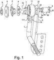
- the angle-adjuster for a headrest comprises a connection arm of the seat (1) and a metallic connection and fixing unit of the headrest (2) .
- connection plate (21) In the upper part of the connection unit of the headrest (2) there is a connection plate (21), at the centre of which there is a central through hole (22); in the lower part of the central through hole (22), on the left side of the connection plate (21), there is a sliding toothing (23).
- connection arm (1) of the seat has a main connection body (11) with a main through hole (12) at the centre opposite the central through hole (22) described above; the right side of the main connection body (11) has a rounded milling (13) in which the sliding toothing (23) is inserted; on the right side of the main body (11) there is a hole (14) with diameter that, proceeding from left to right, progressively decreases determining the first (141), the second (142) and the third section (143) of the hole (14), the latter section (143) communicates with the main hole (12) of the main connection body (11). On the lower end of the third section (143) of the hole (14) there is a series of fan-shaped blocks (51) equally divided and having the main hole (12) of the main connection body (11) as centre.
- Iron inserts (7) are positioned in the positioning grooves (54), arranged between the lower end of the third section (143) of the hole (14) and the inner insert-locking disc (4).
- Grooves (55) are formed in the fan-shaped blocks (51) that act as seats for springs (10). These springs (10) are indeed inserted in the grooves (55): one end of the spring (10) exerts a lower pressure on the bottom of the groove (55), the other end of the spring (10) presses against the inserts (7).
- the inner insert-locking disc (4) is inserted in the third section (143) of the hole (14) and presses against the left end of the fan-shaped block (51); the stop flange (3) is inserted inside the second section (142) of the hole (14) .
- the upper cover (6) covers the left side of the main connection body (11).
- the central hole (22) of the connection plate (21) is a hexagonal hole; the cylindrical body (8), proceeding from left to right, respectively has a portion with hexagonal cross section (81) and a side surface (82) in the form of a metallic bush (82).
- the latter on the left side, has a joint (83) provided with a central screw nut (84); the portion with hexagonal section (81) is inserted at the centre of the central hole (22) of the connection plate (22); the metallic bush (82) is inserted between the hole (12) of the main connection body (11), the central hole of the inner insert-locking disc (4) and the central hole of the stop flange (3); the joint (83) is inserted in the central hole (61) of the upper cover (6); the ring nut (9) is screwed onto the screw nut (84).
- positioning pins (43) and positioning blocks (44) are arranged, and each of them constitutes a positioning unit. Every positioning unit, having the central hole of the inner insert-locking disc (4) as centre, is on the right side of the inner insert-locking disc (4).
- the positioning units correspond one by one to the fan-shaped blocks (51); every positioning pin (43) is inserted in the corresponding cavity (56); the positioning block (44) is inserted in the positioning groove (55) of the corresponding spring (10); each spring (10) is between the positioning block (44) and the left inner surface of the groove (55); the left side of the fan-shaped block (51) is arranged close to the right end of the inner insert-locking disc (4).
- stop teeth (32) On the left side of the stop flange (3) there are stop teeth (32); on the right side of the cover (6) there is a circular flange (62) arranged at the centre of the first section (141) of the hole (14); on the circular flange (62) there is a positioning milling (63) inside which the stop teeth (32) are located.
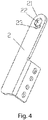
- connection arm of the seat (1) has a connection portion (19) that extends upwards.
- the lower end of the main connection body (11) consists of a connection portion (111) that extends downwards.
- the upper connection portion (19) and the lower connection portion (111) are fixed through bolts.
- connection unit of the headrest (2) has a connection block.
- the rod of the connection arm of the seat (1) has a curved connection part threaded at the end.
- the metal inserts (7) engage, on one side, with the cylindrical wall of the side surface (82) of the cylindrical body (8), on the other side with the inner wall of the third section (143) of the hole (14).
- the metal inserts (7) are arranged between the arched stop blocks (31) of the stop flange (3).
- the present structure controls the rotation angle through the length of the rounded milling (13) and/or of the positioning milling (63), and adjusts the rotation direction of the cylindrical body (8) and therefore of the connection unit of the headrest (2) through the control of the positioning of the inserts (7) inside the respective seats (54).
- connection plate (21) and the upper cover (6) are properly assembled with the cylindrical body (8), they lock together; when the connection plate (21) rotates, the sliding toothing (23) slides in the rounded milling (13), while the upper cover (6) rotates; when the connection plate (21) is rotated to the maximum degree of set angle (i.e. the stop flange 3 and the upper cover 6 have the same rotation angle, while the connection plate 21 and the rounded milling 13 of the main connection body 11 have a rotation angle of 120 degrees more with respect to that of the stop flange 3 with the positioning milling 63 of the upper cover 6), the upper cover (6) actuates the rotation of the stop flange (3), with rotation angle of 120 degrees.
- the maximum degree of set angle i.e. the stop flange 3 and the upper cover 6 have the same rotation angle
- the connection plate 21 and the rounded milling 13 of the main connection body 11 have a rotation angle of 120 degrees more with respect to that of the stop flange 3 with the positioning milling 63 of the upper cover 6
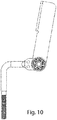
- the arched stop blocks (31) of the stop flange (3) press the inserts (7) (see Fig.10 ), ensuring that the latter (7) separate from the metallic bush (82), in this way stopping the limitation effect of the rotation of the same bush (82), and thus obtaining the return of the rotation structure.
Landscapes
- Engineering & Computer Science (AREA)
- Aviation & Aerospace Engineering (AREA)
- Transportation (AREA)
- Mechanical Engineering (AREA)
- Chair Legs, Seat Parts, And Backrests (AREA)
- Chairs For Special Purposes, Such As Reclining Chairs (AREA)
Claims (7)
- Winkeleinstellelement für Kopfstütze, umfassend einen Verbindungsarm (1) mit dem Sitz eines Stuhls und eine Befestigungseinheit (2) mit der Kopfstütze des Stuhls, dadurch gekennzeichnet, dass die Befestigungseinheit (2) mit der Kopfstütze eine Verbindungsplatte (21) umfasst, wobei der Verbindungsarm (1) mit dem Sitz einen Hauptverbindungskörper (11) mit einem Hauptdurchgangsloch (12) umfasst und ein Loch (14), das mit dem Hauptdurchgangsloch (12) in Verbindung steht, wobei das Loch (14) eine Mehrzahl von gleichmäßig über den Umfang des Loches (14) verteilten, dem Hauptdurchgangsloch (12) zugewandten, fächerförmigen Blöcken (51) aufnimmt, wobei zwischen zwei benachbarten fächerförmigen Blöcken (51) ein Positioniersitz (54) definiert ist, in dem ein Verriegelungseinsatz (7) untergebracht ist, wobei das Winkeleinstellelement einen Anschlagflansch (3) mit einem Durchgangsloch und einer Mehrzahl von gebogenen Anschlagblöcken (31) umfasst, die in Bezug auf den Anschlagflansch (3) zur Innenseite des Hauptdurchgangsloches (12) axial auskragen, um einem jeweiligen Positioniersitz (54) an einem jeweiligen Verriegelungseinsatz (7) zugewandt zu sein, wobei das Winkeleinstellelement einen zylindrischen Körper (8) aufweist, der sich längs erstreckt und in der Drehung fest mit der Verbindungsplatte (21) verbunden ist, wobei der zylindrische Körper (8) durch das Hauptdurchgangsloch (12) des Hauptverbindungskörpers (11), durch das Loch (14) und durch das Durchgangsloch des Anschlagflansches (3) hindurchgeht, wobei der Abschnitt der Einsätze (7), die radial zur Innenseite des Hauptdurchgangsloches (12) auskragen, ausgebildet ist, um durch Bindung die Seitenfläche (82) des zylindrischen Körpers in Eingriff zu nehmen(8), um die Drehung des zylindrischen Körpers (8) im Inneren des Hauptdurchgangsloches (12) in eine erste Drehrichtung zu sperren, wohingegen die Drehung des zylindrischen Körpers (8) im Inneren des Hauptdurchgangsloches (12) in eine zweite Drehrichtung entgegen der ersten Drehrichtung erlaubt ist, wobei der Anschlagflansch (3) in der Lage ist, in einem vorgegebenen Winkel zwischen dem Verbindungsarm (1) und der Befestigungseinheit (2) in Drehung versetzt zu werden, so dass die gebogenen Blöcke (31) gegen die Einsätze (7) gedrückt und aus der Bindungskonfiguration mit dem zylindrischen Körper (8) befreit werden und die Drehung des zylindrischen Körpers (8) im Inneren des Hauptdurchgangsloches (12) auch in die erste Drehrichtung erlaubt wird.
- Winkeleinstellelement für Kopfstütze nach Anspruch 1, dadurch gekennzeichnet, dass im Inneren eines jeden der fächerförmigen Blöcke (51) ein Sitz (55) ausgestaltet ist, um elastische Mittel (10) aufzunehmen, die ausgestaltet sind, um gegen einen jeweiligen Verriegelungseinsatz (7) zu drücken, der in einem jeweiligen Positioniersitz (54) neben dem fächerförmigen Block (51) untergebracht ist.
- Winkeleinstellelement für Kopfstütze nach Anspruch 1 oder 2, dadurch gekennzeichnet, dass es einen Deckel (6) umfasst, der ausgebildet ist, um das Loch (14) zu schließen und sich als eine Einheit mit dem zylindrischen Körper (8) zu drehen, wobei der Deckel (6) auf seiner dem Loch (14) zugewandten Seite wenigstens eine Positionierfräsung (63) umfasst, wobei der Anschlagflansch (3) auf der Seite, die der Seite gegenüberliegt, aus der die gebogenen Blöcke (31) auskragen, wenigstens einen Anschlagzahn (32) aufweist, der dazu geeignet ist, im Inneren der Positionierfräsung (63) zu gleiten, wobei der Anschlagzahn (32) gegen ein Ende der Positionierfräsung (63) an dem vorgegebenen Winkel zwischen dem Verbindungsarm (1) und der Befestigungseinheit (2) in Anschlag geht und den Anschlagflansch (3) um einen derartigen Drehwinkel in Drehung versetzt, dass die gebogenen Blöcke (31) gegen die Einsätze (7) drücken und sie aus der Bindungskonfiguration mit dem zylindrischen Körper (8) befreien.
- Winkeleinstellelement für Kopfstütze nach einem oder mehreren der vorstehenden Ansprüche, dadurch gekennzeichnet, dass es eine innere Einsatzverriegelungsscheibe (4) mit einem Durchgangsloch umfasst, die im Inneren des Loches (14) zwischen den fächerförmigen Blöcken (51) und dem Anschlagflansch (3) angeordnet ist, wobei die innere Einsatzverriegelungsscheibe (4) eine Mehrzahl von Positionierblöcken (44) umfasst, die axial auskragen und jeweils in jeweilige Gehäusesitze (55) der elastischen Mittel (10) eingefügt sind, um die elastischen Mittel (10) im Inneren der Gehäusesitze (55) zu halten.
- Winkeleinstellelement für Kopfstütze nach einem oder mehreren der vorstehenden Ansprüche, dadurch gekennzeichnet, dass die Verbindungsplatte (21) ein dem Hauptdurchgangsloch (12) des Hauptverbindungskörpers (11) gegenüberliegendes, zentrales Durchgangsloch (22) aufweist, wobei das zentrale Durchgangsloch (22) sechseckig ist, wobei der zylindrische Körper (8) einen Abschnitt mit sechseckigem Querschnitt (81) aufweist, der zum Eingriff in das sechseckige, zentrale Durchgangsloch (22) geeignet ist.
- Winkeleinstellelement für Kopfstütze nach einem oder mehreren der vorstehenden Ansprüche, dadurch gekennzeichnet, dass der Abschnitt der radial zum Inneren des Hauptdurchgangsloches (12) auskragenden Einsätze (7) eine seitlich zum jeweiligen fächerförmigen Block (51) hin auskragende Vorwölbung aufweist und ausgebildet ist, um die Bindung des Einsatzes (7) gegen die Seitenfläche (82) des zylindrischen Körpers (8) zu gewährleisten, wenn er in die erste Drehrichtung im Inneren des Hauptdurchgangsloches (12) gedreht wird.
- Winkeleinstellelement für Kopfstütze nach einem oder mehreren der vorstehenden Ansprüche, dadurch gekennzeichnet, dass die gebogenen Blöcke (31) durch das Durchgangsloch der inneren Einsatzverriegelungsscheibe (4) in das Hauptdurchgangsloch (12) des Hauptverbindungskörpers (11) auskragen.
Priority Applications (1)
| Application Number | Priority Date | Filing Date | Title |
|---|---|---|---|
| PL17196108T PL3308675T3 (pl) | 2016-10-12 | 2017-10-12 | Regulator kąta zagłówka |
Applications Claiming Priority (1)
| Application Number | Priority Date | Filing Date | Title |
|---|---|---|---|
| CN201621115827.8U CN206473072U (zh) | 2016-10-12 | 2016-10-12 | 一种头枕角度调节器 |
Publications (2)
| Publication Number | Publication Date |
|---|---|
| EP3308675A1 EP3308675A1 (de) | 2018-04-18 |
| EP3308675B1 true EP3308675B1 (de) | 2019-05-29 |
Family
ID=59756311
Family Applications (1)
| Application Number | Title | Priority Date | Filing Date |
|---|---|---|---|
| EP17196108.9A Active EP3308675B1 (de) | 2016-10-12 | 2017-10-12 | Winkeleinstellelement für eine kopfstütze |
Country Status (4)
| Country | Link |
|---|---|
| EP (1) | EP3308675B1 (de) |
| CN (1) | CN206473072U (de) |
| ES (1) | ES2743034T3 (de) |
| PL (1) | PL3308675T3 (de) |
Cited By (1)
| Publication number | Priority date | Publication date | Assignee | Title |
|---|---|---|---|---|
| EP3871563B1 (de) * | 2020-02-27 | 2025-07-16 | Lusch GmbH | Schwenkgelenk zum verstellen eines funktionsteils mit einem klemmelement |
Families Citing this family (3)
| Publication number | Priority date | Publication date | Assignee | Title |
|---|---|---|---|---|
| CN108372818B (zh) * | 2016-10-12 | 2021-08-06 | 东莞市振鑫家具配件有限公司 | 一种头枕角度调节器 |
| CN109720393B (zh) * | 2018-11-28 | 2021-06-15 | 湖州埭溪振华工贸有限公司 | 新型角度调节器 |
| CN113325587A (zh) * | 2021-05-28 | 2021-08-31 | 歌尔股份有限公司 | 一种调节机构及头戴显示设备 |
Family Cites Families (3)
| Publication number | Priority date | Publication date | Assignee | Title |
|---|---|---|---|---|
| CN202457357U (zh) | 2012-03-06 | 2012-10-03 | 张国雄 | 头枕角度调节器 |
| CN103393302B (zh) * | 2013-08-02 | 2016-01-13 | 上海延锋江森座椅有限公司 | 单向调节可复位调角器 |
| DE102015117461B4 (de) * | 2014-12-30 | 2022-03-17 | Dongguan Weihong Hardware And Plastic Products Co., Ltd. | Stützsystem zum Einstellen einer Kopfstütze |
-
2016
- 2016-10-12 CN CN201621115827.8U patent/CN206473072U/zh not_active Expired - Fee Related
-
2017
- 2017-10-12 EP EP17196108.9A patent/EP3308675B1/de active Active
- 2017-10-12 ES ES17196108T patent/ES2743034T3/es active Active
- 2017-10-12 PL PL17196108T patent/PL3308675T3/pl unknown
Non-Patent Citations (1)
| Title |
|---|
| None * |
Cited By (1)
| Publication number | Priority date | Publication date | Assignee | Title |
|---|---|---|---|---|
| EP3871563B1 (de) * | 2020-02-27 | 2025-07-16 | Lusch GmbH | Schwenkgelenk zum verstellen eines funktionsteils mit einem klemmelement |
Also Published As
| Publication number | Publication date |
|---|---|
| CN206473072U (zh) | 2017-09-08 |
| EP3308675A1 (de) | 2018-04-18 |
| PL3308675T3 (pl) | 2019-12-31 |
| ES2743034T3 (es) | 2020-02-18 |
Similar Documents
| Publication | Publication Date | Title |
|---|---|---|
| EP3308675B1 (de) | Winkeleinstellelement für eine kopfstütze | |
| US9616780B2 (en) | Device for adjusting the tilt of a vehicle seat by smaller increments | |
| US8936526B2 (en) | Adjustment mechanism for vehicle seat, vehicle seat comprising such a mechanism | |
| EP3208140B1 (de) | Drehmomentübertragungssteuerungsmechanismus und sitzstruktur | |
| CN101386274B (zh) | 机动车辆座椅倾斜调节机构 | |
| EP2975971B1 (de) | Plattenneigungsvorrichtung mit kegelförmiger nockenoberfläche | |
| EP2634040B1 (de) | Armlehne mit verstellbarer Neigung, insbesondere für Fahrzeuge | |
| US10610018B1 (en) | Dual cam recliner mechanism | |
| JP6479332B2 (ja) | 過負荷保護機能付き駆動装置 | |
| KR101574069B1 (ko) | 자동차 시트의 조절 장치용 핏팅 | |
| EP3194804B1 (de) | Scheibenbremse für ein nutzfahrzeug | |
| DE10139911A1 (de) | Scheibenbremse mit Nachstellermodul | |
| US9315122B2 (en) | Seat fitting for a motor vehicle seat | |
| DE102016005668A1 (de) | Elektrische Scheibenbremse | |
| CN102858205A (zh) | 锁止配件 | |
| DE102018219662B4 (de) | Pumpvorrichtung für einen fahrzeugsitz | |
| CN104235310A (zh) | 齿轮装置 | |
| US9016153B2 (en) | Adjusting device for a vehicle seat having a self-adjusting brake | |
| GB2477477A (en) | Hob | |
| US11209042B2 (en) | Pivot fitting and piece of furniture | |
| DE102010055529A1 (de) | Rastgelenk zum Verstellen eines Sitz- und/oder Liegemöbels | |
| US11149816B2 (en) | Vehicle seat element for a vehicle seat with a residual spring travel adjustment device | |
| CN104973118A (zh) | 转向管柱总成及汽车 | |
| US10787102B2 (en) | Recliner mechanism | |
| EP2410198B1 (de) | Scheibenbremse für ein Nutzfahrzeug |
Legal Events
| Date | Code | Title | Description |
|---|---|---|---|
| PUAI | Public reference made under article 153(3) epc to a published international application that has entered the european phase |
Free format text: ORIGINAL CODE: 0009012 |
|
| STAA | Information on the status of an ep patent application or granted ep patent |
Free format text: STATUS: THE APPLICATION HAS BEEN PUBLISHED |
|
| AK | Designated contracting states |
Kind code of ref document: A1 Designated state(s): AL AT BE BG CH CY CZ DE DK EE ES FI FR GB GR HR HU IE IS IT LI LT LU LV MC MK MT NL NO PL PT RO RS SE SI SK SM TR |
|
| AX | Request for extension of the european patent |
Extension state: BA ME |
|
| STAA | Information on the status of an ep patent application or granted ep patent |
Free format text: STATUS: REQUEST FOR EXAMINATION WAS MADE |
|
| 17P | Request for examination filed |
Effective date: 20181015 |
|
| RAV | Requested validation state of the european patent: fee paid |
Extension state: MD Effective date: 20181015 |
|
| RAX | Requested extension states of the european patent have changed |
Extension state: BA Payment date: 20181015 Extension state: ME Payment date: 20181015 |
|
| RBV | Designated contracting states (corrected) |
Designated state(s): AL AT BE BG CH CY CZ DE DK EE ES FI FR GB GR HR HU IE IS IT LI LT LU LV MC MK MT NL NO PL PT RO RS SE SI SK SM TR |
|
| GRAP | Despatch of communication of intention to grant a patent |
Free format text: ORIGINAL CODE: EPIDOSNIGR1 |
|
| STAA | Information on the status of an ep patent application or granted ep patent |
Free format text: STATUS: GRANT OF PATENT IS INTENDED |
|
| INTG | Intention to grant announced |
Effective date: 20190214 |
|
| GRAS | Grant fee paid |
Free format text: ORIGINAL CODE: EPIDOSNIGR3 |
|
| GRAA | (expected) grant |
Free format text: ORIGINAL CODE: 0009210 |
|
| STAA | Information on the status of an ep patent application or granted ep patent |
Free format text: STATUS: THE PATENT HAS BEEN GRANTED |
|
| AK | Designated contracting states |
Kind code of ref document: B1 Designated state(s): AL AT BE BG CH CY CZ DE DK EE ES FI FR GB GR HR HU IE IS IT LI LT LU LV MC MK MT NL NO PL PT RO RS SE SI SK SM TR |
|
| AX | Request for extension of the european patent |
Extension state: BA ME |
|
| REG | Reference to a national code |
Ref country code: GB Ref legal event code: FG4D |
|
| REG | Reference to a national code |
Ref country code: CH Ref legal event code: EP |
|
| REG | Reference to a national code |
Ref country code: DE Ref legal event code: R096 Ref document number: 602017004202 Country of ref document: DE |
|
| REG | Reference to a national code |
Ref country code: AT Ref legal event code: REF Ref document number: 1137738 Country of ref document: AT Kind code of ref document: T Effective date: 20190615 |
|
| REG | Reference to a national code |
Ref country code: IE Ref legal event code: FG4D |
|
| REG | Reference to a national code |
Ref country code: NL Ref legal event code: MP Effective date: 20190529 |
|
| REG | Reference to a national code |
Ref country code: LT Ref legal event code: MG4D |
|
| PG25 | Lapsed in a contracting state [announced via postgrant information from national office to epo] |
Ref country code: AL Free format text: LAPSE BECAUSE OF FAILURE TO SUBMIT A TRANSLATION OF THE DESCRIPTION OR TO PAY THE FEE WITHIN THE PRESCRIBED TIME-LIMIT Effective date: 20190529 Ref country code: SE Free format text: LAPSE BECAUSE OF FAILURE TO SUBMIT A TRANSLATION OF THE DESCRIPTION OR TO PAY THE FEE WITHIN THE PRESCRIBED TIME-LIMIT Effective date: 20190529 Ref country code: HR Free format text: LAPSE BECAUSE OF FAILURE TO SUBMIT A TRANSLATION OF THE DESCRIPTION OR TO PAY THE FEE WITHIN THE PRESCRIBED TIME-LIMIT Effective date: 20190529 Ref country code: FI Free format text: LAPSE BECAUSE OF FAILURE TO SUBMIT A TRANSLATION OF THE DESCRIPTION OR TO PAY THE FEE WITHIN THE PRESCRIBED TIME-LIMIT Effective date: 20190529 Ref country code: NO Free format text: LAPSE BECAUSE OF FAILURE TO SUBMIT A TRANSLATION OF THE DESCRIPTION OR TO PAY THE FEE WITHIN THE PRESCRIBED TIME-LIMIT Effective date: 20190829 Ref country code: LT Free format text: LAPSE BECAUSE OF FAILURE TO SUBMIT A TRANSLATION OF THE DESCRIPTION OR TO PAY THE FEE WITHIN THE PRESCRIBED TIME-LIMIT Effective date: 20190529 Ref country code: PT Free format text: LAPSE BECAUSE OF FAILURE TO SUBMIT A TRANSLATION OF THE DESCRIPTION OR TO PAY THE FEE WITHIN THE PRESCRIBED TIME-LIMIT Effective date: 20190930 |
|
| PG25 | Lapsed in a contracting state [announced via postgrant information from national office to epo] |
Ref country code: GR Free format text: LAPSE BECAUSE OF FAILURE TO SUBMIT A TRANSLATION OF THE DESCRIPTION OR TO PAY THE FEE WITHIN THE PRESCRIBED TIME-LIMIT Effective date: 20190830 Ref country code: BG Free format text: LAPSE BECAUSE OF FAILURE TO SUBMIT A TRANSLATION OF THE DESCRIPTION OR TO PAY THE FEE WITHIN THE PRESCRIBED TIME-LIMIT Effective date: 20190829 Ref country code: LV Free format text: LAPSE BECAUSE OF FAILURE TO SUBMIT A TRANSLATION OF THE DESCRIPTION OR TO PAY THE FEE WITHIN THE PRESCRIBED TIME-LIMIT Effective date: 20190529 Ref country code: RS Free format text: LAPSE BECAUSE OF FAILURE TO SUBMIT A TRANSLATION OF THE DESCRIPTION OR TO PAY THE FEE WITHIN THE PRESCRIBED TIME-LIMIT Effective date: 20190529 |
|
| REG | Reference to a national code |
Ref country code: AT Ref legal event code: MK05 Ref document number: 1137738 Country of ref document: AT Kind code of ref document: T Effective date: 20190529 |
|
| PG25 | Lapsed in a contracting state [announced via postgrant information from national office to epo] |
Ref country code: DK Free format text: LAPSE BECAUSE OF FAILURE TO SUBMIT A TRANSLATION OF THE DESCRIPTION OR TO PAY THE FEE WITHIN THE PRESCRIBED TIME-LIMIT Effective date: 20190529 Ref country code: EE Free format text: LAPSE BECAUSE OF FAILURE TO SUBMIT A TRANSLATION OF THE DESCRIPTION OR TO PAY THE FEE WITHIN THE PRESCRIBED TIME-LIMIT Effective date: 20190529 Ref country code: RO Free format text: LAPSE BECAUSE OF FAILURE TO SUBMIT A TRANSLATION OF THE DESCRIPTION OR TO PAY THE FEE WITHIN THE PRESCRIBED TIME-LIMIT Effective date: 20190529 Ref country code: SK Free format text: LAPSE BECAUSE OF FAILURE TO SUBMIT A TRANSLATION OF THE DESCRIPTION OR TO PAY THE FEE WITHIN THE PRESCRIBED TIME-LIMIT Effective date: 20190529 Ref country code: CZ Free format text: LAPSE BECAUSE OF FAILURE TO SUBMIT A TRANSLATION OF THE DESCRIPTION OR TO PAY THE FEE WITHIN THE PRESCRIBED TIME-LIMIT Effective date: 20190529 Ref country code: NL Free format text: LAPSE BECAUSE OF FAILURE TO SUBMIT A TRANSLATION OF THE DESCRIPTION OR TO PAY THE FEE WITHIN THE PRESCRIBED TIME-LIMIT Effective date: 20190529 Ref country code: AT Free format text: LAPSE BECAUSE OF FAILURE TO SUBMIT A TRANSLATION OF THE DESCRIPTION OR TO PAY THE FEE WITHIN THE PRESCRIBED TIME-LIMIT Effective date: 20190529 |
|
| PGFP | Annual fee paid to national office [announced via postgrant information from national office to epo] |
Ref country code: DE Payment date: 20191009 Year of fee payment: 3 |
|
| VS25 | Lapsed in a validation state [announced via postgrant information from nat. office to epo] |
Ref country code: MD Free format text: LAPSE BECAUSE OF FAILURE TO SUBMIT A TRANSLATION OF THE DESCRIPTION OR TO PAY THE FEE WITHIN THE PRESCRIBED TIME-LIMIT Effective date: 20190529 |
|
| REG | Reference to a national code |
Ref country code: ES Ref legal event code: FG2A Ref document number: 2743034 Country of ref document: ES Kind code of ref document: T3 Effective date: 20200218 |
|
| PG25 | Lapsed in a contracting state [announced via postgrant information from national office to epo] |
Ref country code: SM Free format text: LAPSE BECAUSE OF FAILURE TO SUBMIT A TRANSLATION OF THE DESCRIPTION OR TO PAY THE FEE WITHIN THE PRESCRIBED TIME-LIMIT Effective date: 20190529 |
|
| PGFP | Annual fee paid to national office [announced via postgrant information from national office to epo] |
Ref country code: FR Payment date: 20191010 Year of fee payment: 3 Ref country code: PL Payment date: 20191008 Year of fee payment: 3 Ref country code: ES Payment date: 20191113 Year of fee payment: 3 |
|
| REG | Reference to a national code |
Ref country code: DE Ref legal event code: R097 Ref document number: 602017004202 Country of ref document: DE |
|
| PG25 | Lapsed in a contracting state [announced via postgrant information from national office to epo] |
Ref country code: TR Free format text: LAPSE BECAUSE OF FAILURE TO SUBMIT A TRANSLATION OF THE DESCRIPTION OR TO PAY THE FEE WITHIN THE PRESCRIBED TIME-LIMIT Effective date: 20190529 |
|
| PLBE | No opposition filed within time limit |
Free format text: ORIGINAL CODE: 0009261 |
|
| STAA | Information on the status of an ep patent application or granted ep patent |
Free format text: STATUS: NO OPPOSITION FILED WITHIN TIME LIMIT |
|
| 26N | No opposition filed |
Effective date: 20200303 |
|
| PG25 | Lapsed in a contracting state [announced via postgrant information from national office to epo] |
Ref country code: SI Free format text: LAPSE BECAUSE OF FAILURE TO SUBMIT A TRANSLATION OF THE DESCRIPTION OR TO PAY THE FEE WITHIN THE PRESCRIBED TIME-LIMIT Effective date: 20190529 Ref country code: MC Free format text: LAPSE BECAUSE OF FAILURE TO SUBMIT A TRANSLATION OF THE DESCRIPTION OR TO PAY THE FEE WITHIN THE PRESCRIBED TIME-LIMIT Effective date: 20190529 |
|
| PG25 | Lapsed in a contracting state [announced via postgrant information from national office to epo] |
Ref country code: LU Free format text: LAPSE BECAUSE OF NON-PAYMENT OF DUE FEES Effective date: 20191012 |
|
| REG | Reference to a national code |
Ref country code: BE Ref legal event code: MM Effective date: 20191031 |
|
| PG25 | Lapsed in a contracting state [announced via postgrant information from national office to epo] |
Ref country code: BE Free format text: LAPSE BECAUSE OF NON-PAYMENT OF DUE FEES Effective date: 20191031 |
|
| PG25 | Lapsed in a contracting state [announced via postgrant information from national office to epo] |
Ref country code: IE Free format text: LAPSE BECAUSE OF NON-PAYMENT OF DUE FEES Effective date: 20191012 |
|
| PGFP | Annual fee paid to national office [announced via postgrant information from national office to epo] |
Ref country code: IT Payment date: 20201031 Year of fee payment: 4 |
|
| REG | Reference to a national code |
Ref country code: DE Ref legal event code: R119 Ref document number: 602017004202 Country of ref document: DE |
|
| PG25 | Lapsed in a contracting state [announced via postgrant information from national office to epo] |
Ref country code: CY Free format text: LAPSE BECAUSE OF FAILURE TO SUBMIT A TRANSLATION OF THE DESCRIPTION OR TO PAY THE FEE WITHIN THE PRESCRIBED TIME-LIMIT Effective date: 20190529 |
|
| REG | Reference to a national code |
Ref country code: CH Ref legal event code: PL |
|
| PG25 | Lapsed in a contracting state [announced via postgrant information from national office to epo] |
Ref country code: IS Free format text: LAPSE BECAUSE OF FAILURE TO SUBMIT A TRANSLATION OF THE DESCRIPTION OR TO PAY THE FEE WITHIN THE PRESCRIBED TIME-LIMIT Effective date: 20190929 Ref country code: LI Free format text: LAPSE BECAUSE OF FAILURE TO SUBMIT A TRANSLATION OF THE DESCRIPTION OR TO PAY THE FEE WITHIN THE PRESCRIBED TIME-LIMIT Effective date: 20201031 Ref country code: CH Free format text: LAPSE BECAUSE OF FAILURE TO SUBMIT A TRANSLATION OF THE DESCRIPTION OR TO PAY THE FEE WITHIN THE PRESCRIBED TIME-LIMIT Effective date: 20201031 |
|
| PG25 | Lapsed in a contracting state [announced via postgrant information from national office to epo] |
Ref country code: MT Free format text: LAPSE BECAUSE OF FAILURE TO SUBMIT A TRANSLATION OF THE DESCRIPTION OR TO PAY THE FEE WITHIN THE PRESCRIBED TIME-LIMIT Effective date: 20190529 Ref country code: HU Free format text: LAPSE BECAUSE OF FAILURE TO SUBMIT A TRANSLATION OF THE DESCRIPTION OR TO PAY THE FEE WITHIN THE PRESCRIBED TIME-LIMIT; INVALID AB INITIO Effective date: 20171012 Ref country code: DE Free format text: LAPSE BECAUSE OF NON-PAYMENT OF DUE FEES Effective date: 20210501 Ref country code: FR Free format text: LAPSE BECAUSE OF NON-PAYMENT OF DUE FEES Effective date: 20201031 |
|
| REG | Reference to a national code |
Ref country code: ES Ref legal event code: FD2A Effective date: 20220119 |
|
| GBPC | Gb: european patent ceased through non-payment of renewal fee |
Effective date: 20211012 |
|
| PG25 | Lapsed in a contracting state [announced via postgrant information from national office to epo] |
Ref country code: MK Free format text: LAPSE BECAUSE OF FAILURE TO SUBMIT A TRANSLATION OF THE DESCRIPTION OR TO PAY THE FEE WITHIN THE PRESCRIBED TIME-LIMIT Effective date: 20190529 |
|
| PG25 | Lapsed in a contracting state [announced via postgrant information from national office to epo] |
Ref country code: GB Free format text: LAPSE BECAUSE OF NON-PAYMENT OF DUE FEES Effective date: 20211012 Ref country code: ES Free format text: LAPSE BECAUSE OF NON-PAYMENT OF DUE FEES Effective date: 20201013 |
|
| PG25 | Lapsed in a contracting state [announced via postgrant information from national office to epo] |
Ref country code: IT Free format text: LAPSE BECAUSE OF NON-PAYMENT OF DUE FEES Effective date: 20211012 |
|
| PG25 | Lapsed in a contracting state [announced via postgrant information from national office to epo] |
Ref country code: PL Free format text: LAPSE BECAUSE OF NON-PAYMENT OF DUE FEES Effective date: 20201012 |